Kollmorgen AKD-C01007-MCEC Benutzerhandbuch
Inhaltsverzeichnis
Quicklinks
®
AKD
Benutzerhandbuch
Ausgabe: Revision Mai 2014, Revision M
Gültig für Firmware Version 1.12
Teilenummer 903-200006-01
Bewahren Sie alle Anleitungen während der gesamten Nutzungsdauer des Produkts als Produktkomponente auf.
Händigen Sie alle Anleitungen künftigen Anwendern/Besitzern des Produkts aus.
Kapitel
Inhaltsverzeichnis
Fehlerbehebung

Verwandte Anleitungen für Kollmorgen AKD-C01007-MCEC


Inhaltszusammenfassung für Kollmorgen AKD-C01007-MCEC
- Seite 1 ® Benutzerhandbuch Ausgabe: Revision Mai 2014, Revision M Gültig für Firmware Version 1.12 Teilenummer 903-200006-01 Bewahren Sie alle Anleitungen während der gesamten Nutzungsdauer des Produkts als Produktkomponente auf. Händigen Sie alle Anleitungen künftigen Anwendern/Besitzern des Produkts aus.
- Seite 2 M_01-12 1.12.0 Steuerkarte Rev. 9 Warenzeichen AKD ist ein eingetragenes Warenzeichen der KOLLMORGEN Corporation. EnDat ist ein eingetragenes Warenzeichen der Dr. Johannes Heidenhain GmbH. EtherCAT ist ein eingetragenes Warenzeichen und patentierte Technologie, lizensiert von der Beckhoff Automation GmbH, Deutschland. Ethernet/IP ist ein eingetragenes Warenzeichen der ODVA, Inc.
- Seite 3 Ankündigung vorbehalten. Gedruckt in den USA. Dieses Dokument ist geistiges Eigentum von KOLLMORGEN. Alle Rechte vorbehalten. Kein Teil dieses Werkes darf in irgendeiner Form (Fotokopie, Mikrofilm oder in einem anderen Verfahren) ohne schriftliche Genehmigung von KOLLMORGEN reproduziert oder unter Verwendung elektronischer Systeme verarbeitet, vervielfältigt oder verbreitet werden.
-
Seite 4: Inhaltsverzeichnis
5.2.2.2 Statische IP-Adressierung – Drehschalter Geräte mit zwei Drehschaltern Geräte mit einem Drehschalter 5.2.2.3 Statische IP-Adressierung – Zuweisung per Software 5.2.2.4 Wiederherstellen der Kommunikation mit einem Gerät auf einer unerreichbaren IP Adresse 5.3 Drehschalter 5.3.1 Übersicht KOLLMORGEN | Mai 2014... - Seite 5 8 Konfiguration der Motoreinstellungen 8.1 Motor 8.1.1 Übersicht 8.1.2 Motor-Setup 8.1.3 Verwendung der Bidlschirmseite Motor 8.1.4 Auswahl eines Motors 8.1.5 Konfiguration kundenspezifischer Motoren 8.1.5.1 Validierung von Motorparametern 8.1.6 Motor Derating 8.1.7 Motor Temperatur 8.2 Rückführung 1 8.2.1 Übersicht KOLLMORGEN | Mai 2014...
- Seite 6 8.3.1.9 Ausgangs Modi 15, 16, und 17, emulierter Encoder von Schrittmotor Steuerung. 8.3.1.10 Auflösung 8.4 Rückführgeräte ohne Plug & Play 8.4.1 Parameter 8.4.2 Berechnungen Stromregler Geschwindigkeitsregler Manuelles Tuning Eingabe - Motordaten Konstanten Ausgabe - Regelkreis-Verstärkungen 8.5 Foldback 8.5.1 Servoverstärker-Foldback KOLLMORGEN | Mai 2014...
- Seite 7 12.1.5.2 Digitale Eingänge 3 bis 7 12.1.5.3 Digitaler Eingang 8 (ENABLE) 12.1.6 Optionskarte I/Os 12.2 Befehls-Buffer 12.2.1 Übersicht 12.2.2 Bearbeitung der Befehlspuffer 12.2.3 Verhalten des Befehlspuffers 12.2.4 Verzögerungen für den Puffer 12.3 Analogeingang 12.4 Analogausgang 12.5 Elektronisches Getriebe 12.5.1 Übersicht KOLLMORGEN | Mai 2014...
- Seite 8 13.2.1.1 Service 13.2.1.2 Feldbus 13.2.1.3 Elektronisches Getriebe 13.2.1.4 Analog 13.2.2 Betriebsart 13.3 Stromregelkreis 13.3.1 Übersicht 13.3.2 Stromregelkreis-Verstärkung 13.3.3 Anpassung des Stromregelkreises 13.3.3.1 Verwendung des Bildschirms „KP-Anpassung“ in WorkBench Verwendung des Terminal-Bildschirms für die KP-Anpassung 13.4 Geschwindigkeitsregelkreis 13.4.1 Übersicht KOLLMORGEN | Mai 2014...
- Seite 9 Homing Mode 10: Referenzieren auf mechanischen Anschlag mit Index Homing Mode 11: Referenzierung auf Indexsignal Homing Mode 12: Referenzierung auf Referenzschalter mit mechanischem Anschlag Homing Mode 13: Absolut-Modus - Rückführungsposition verwenden Homing Mode 14: Referenzierung auf Referenzschalter für rotatorische Anwendungen. KOLLMORGEN | Mai 2014...
- Seite 10 1:1 Interpolation Einschränkungen 14.4.4.9 Profiltabellen-Interpolation Einschränkungen Start ab einer Geschwindigkeit von Null ohne fliegenden Wechsel zu einem nachfolgenden Fahrauftrag. Während eines fliegenden Wechsels Bewegung in dieselbe Richtung Bewegung in unterschiedliche Richtungen 14.5 Tippbetrieb 14.6 Status des Antriebs KOLLMORGEN | Mai 2014...
- Seite 11 16.4.6 Verwendung von Anti-Resonanzfiltern 16.4.6.1 Arten von Anti-Resonanzfiltern 16.4.6.2 BiQuad-Berechnungen 16.4.6.3 Gängige Einsatzmöglichkeiten von Anti-Resonanzfiltern 17 Oszilloskop 17.1 Übersicht 17.2 Verwendung des Oszilloskops 17.2.1 Registerkarte „Kanäle“des Oszilloskops 17.2.1.1 Spalte „Quelle“ 17.2.1.2 Spalte „Farbe“ 17.2.1.3 Spalte „Ausblenden“ KOLLMORGEN | Mai 2014...
- Seite 12 19 Fehler und Warnungen 19.1 Fehler und Warnmeldungen 19.2 Zusätzliche Fehlermeldungen AKD-T 19.3 SD Karte Fehler 19.4 Fehler löschen 19.5 Fehlermeldungen in Bezug auf Parameter und Befehle 19.6 CANopen Notfall-Meldungen und Fehlercodes 19.7 Unbekannter Fehler 19.7.1 Maßnahmen KOLLMORGEN | Mai 2014...
- Seite 13 22.14.1 CW / CCW Eingang 5 V (X9) 22.14.2 CW / CCW Eingang 24 V (X7) 22.15 Feedback Stecker (X10) 22.16 Feedback Stecker (X9) 22.17 Feedback Stecker (X7) 23 Feldbus-Handbücher 23.0.1 Feldbus-Handbücher 23.0.1.1 AKD Modbus Kommunikation 23.0.1.2 AKD EtherCAT Kommunikation KOLLMORGEN | Mai 2014...
- Seite 14 Modbus Fehlerbeschreibungen 24 Anhang A: Parameter and Command Reference Guide 24.1 About the Parameter and Command Reference Guide 24.1.1 Parameter and Command Naming Conventions 24.1.2 Summary of Parameters and Commands 24.2 AIN Parameters 24.2.1 AIN.CUTOFF 24.2.2 AIN.DEADBAND KOLLMORGEN | Mai 2014...
- Seite 15 24.5 AOUT2 Parameters 24.5.1 AOUT2.CUTOFF 24.5.2 AOUT2.MODE 24.5.3 AOUT2.OFFSET 24.5.4 AOUT2.VALUE 24.5.5 AOUT.VALUEU 24.6 BODE Parameters 24.6.1 BODE.EXCITEGAP 24.6.2 BODE.FREQ 24.6.3 BODE.IAMP 24.6.4 BODE.IFLIMIT 24.6.5 BODE.IFTHRESH 24.6.6 BODE.INJECTPOINT 24.6.7 BODE.MODE 24.6.8 BODE.MODETIMER 24.6.9 BODE.PRBDEPTH 24.6.10 BODE.VAMP KOLLMORGEN | Mai 2014...
- Seite 16 24.10.11 DIN21.FILTER to DIN32.FILTER 24.10.12 DIN21.STATE to DIN32.STATE 24.11 DIO Parameters 24.11.1 DIO9.INV to DIO11.INV 24.11.2 DIO9.DIR to DIO11.DIR 24.12 DOUT Parameters 24.12.1 DOUT.CTRL 24.12.2 DOUT.RELAYMODE 24.12.3 DOUT.STATES 24.12.4 DOUT1.MODE to DOUT2.MODE 24.12.5 DOUT1.PARAM AND DOUT2.PARAM KOLLMORGEN | Mai 2014...
- Seite 17 24.13.22 DRV.EMUEMODE 24.13.23 DRV.EMUEMTURN 24.13.24 DRV.EMUEPULSEWIDTH 24.13.25 DRV.EMUERES 24.13.26 DRV.EMUEZOFFSET 24.13.27 DRV.EN 24.13.28 DRV.ENDEFAULT 24.13.29 DRV.ERRORLIST 24.13.30 DRV.FAULTHIST 24.13.31 DRV.FAULT1 to DRV.FAULT10 24.13.32 DRV.FAULTS 24.13.33 DRV.HANDWHEEL 24.13.34 DRV.HANDWHEELSRC 24.13.35 DRV.HELP 24.13.36 DRV.HELPALL 24.13.37 DRV.HWENABLE 24.13.38 DRV.HWENDELAY KOLLMORGEN | Mai 2014...
- Seite 18 24.13.68 DRV.WARNING1 to DRV.WARNING3 24.13.69 DRV.WARNINGS 24.13.70 DRV.ZERO 24.14 EIP Parameters 24.14.1 EIP.CONNECTED 24.14.2 EIP.POSUNIT 24.14.3 EIP.PROFUNIT 24.15 FAULT Parameters 24.15.1 FAULTx.ACTION 24.15.2 FAULT564.ACTION, FAULT565.ACTION 24.16 FB1 Parameters 24.16.1 FB1.BISSBITS 24.16.2 FB1.DIAG 24.16.3 FB1.ENCRES 24.16.4 FB1.FAULTS 24.16.5 FB1.HALLSTATE KOLLMORGEN | Mai 2014...
- Seite 19 24.16.36 FB1.USERDWORD0 to FB1.USERDWORD1 24.16.37 FB1.USERWORD0 to FB1.USERWORD3 24.17 FB2 Parameters 24.17.1 FB2.DIR 24.17.2 FB2.ENCRES 24.17.3 FB2.MODE 24.17.4 FB2.MOTORPHASE 24.17.5 FB2.MOTORPOLES 24.17.6 FB2.P 24.17.7 FB2.PIN 24.17.8 FB2.POFFSET 24.17.9 FB2.POUT 24.17.10 FB2.PUNIT 24.17.11 FB2.SOURCE 24.18 FB3 Parameters KOLLMORGEN | Mai 2014...
- Seite 20 24.20.5 GEAR.MOVE 24.20.6 GEAR.OUT 24.20.7 GEAR.VMAX 24.21 GUI Parameters 24.21.1 GUI.DISPLAY 24.21.2 GUI.DISPLAYS 24.21.3 GUI.PARAM01 24.21.4 GUI.PARAM02 24.21.5 GUI.PARAM03 24.21.6 GUI.PARAM04 24.21.7 GUI.PARAM05 24.21.8 GUI.PARAM06 24.21.9 GUI.PARAM07 24.21.10 GUI.PARAM08 24.21.11 GUI.PARAM09 24.21.12 GUI.PARAM10 24.22 HOME Parameters KOLLMORGEN | Mai 2014...
- Seite 21 24.24.10 IL.FF 24.24.11 IL.FOLDFTHRESH 24.24.12 IL.FOLDFTHRESHU 24.24.13 IL.FOLDWTHRESH 24.24.14 IL.FRICTION 24.24.15 IL.IFOLD 24.24.16 IL.IUFB 24.24.17 IL.IVFB 24.24.18 IL.KACCFF 24.24.19 IL.KBUSFF 24.24.20 IL.KP 24.24.21 IL.KPDRATIO 24.24.22 IL.KPLOOKUPINDEX 24.24.23 IL.KPLOOKUPVALUE 24.24.24 IL.KPLOOKUPVALUES 24.24.25 IL.KVFF 24.24.26 IL.LIMITN 24.24.27 IL.LIMITP KOLLMORGEN | Mai 2014...
- Seite 22 24.28 MOTOR Parameters 24.28.1 MOTOR.AUTOSET 24.28.2 MOTOR.BRAKE 24.28.3 MOTOR.BRAKEIMM 24.28.4 MOTOR.BRAKERLS 24.28.5 MOTOR.BRAKESTATE 24.28.6 MOTOR.CTF0 24.28.7 MOTOR.ICONT 24.28.8 MOTOR.IDDATAVALID 24.28.9 MOTOR.IDMAX 24.28.10 MOTOR.IMID 24.28.11 MOTOR.IMTR 24.28.12 MOTOR.INERTIA 24.28.13 MOTOR.IPEAK 24.28.14 MOTOR.KE 24.28.15 MOTOR.KT 24.28.16 MOTOR.LDLL 24.28.17 MOTOR.LISAT KOLLMORGEN | Mai 2014...
- Seite 23 24.29.4 MT.CONTINUE 24.29.5 MT.DEC 24.29.6 MT.EMERGMT 24.29.7 MT.FEEDRATE 24.29.8 MT.LIST 24.29.9 MT.LOAD 24.29.10 MT.MOVE 24.29.11 MT.MTNEXT 24.29.12 MT.NUM 24.29.13 MT.P 24.29.14 MT.PARAMS 24.29.15 MT.SET 24.29.16 MT.TNEXT 24.29.17 MT.TNUM 24.29.18 MT.TNVSAVE 24.29.19 MT.TPOSWND 24.29.20 MT.TVELWND 24.29.21 MT.V KOLLMORGEN | Mai 2014...
- Seite 24 24.33.2 REC.CH1 to REC.CH6 1031 24.33.3 REC.DONE 1032 24.33.4 REC.GAP 1033 24.33.5 REC.NUMPOINTS 1034 24.33.6 REC.OFF 1035 24.33.7 REC.RECPRMLIST 1036 24.33.8 REC.RETRIEVE 1037 24.33.9 REC.RETRIEVEDATA 1038 24.33.10 REC.RETRIEVEFRMT 1040 24.33.11 REC.RETRIEVEHDR 1042 24.33.12 REC.RETRIEVESIZE 1043 24.33.13 REC.STOPTYPE 1044 KOLLMORGEN | Mai 2014...
- Seite 25 1087 24.40 STRINGS Parameters 1088 24.40.1 STRINGS.I2TFTHRESH 1089 24.40.2 STRINGS.I2TVALUE 1090 24.40.3 STRINGS.I2TWTHRESH 1091 24.40.4 STRINGS.IFTHRESH 1092 24.40.5 STRINGS.IVALUE 1093 24.40.6 STRINGS.IWTHRESH 1094 24.40.7 STRINGS.STOSTATUS 1095 24.40.8 STRINGS.VVALUE 1096 24.41 SWLS Parameters 1097 24.41.1 SWLS.EN 1098 KOLLMORGEN | Mai 2014...
- Seite 26 24.46.6 VL.BUSFF 1151 24.46.7 VL.CMD 1152 24.46.8 VL.CMDU 1154 24.46.9 VL.ERR 1156 24.46.10 VL.FB 1157 24.46.11 VL.FBFILTER 1158 24.46.12 VL.FBSOURCE 1159 24.46.13 VL.FBUNFILTERED 1160 24.46.14 VL.FF 1161 24.46.15 VL.GENMODE 1162 24.46.16 VL.KBUSFF 1163 24.46.17 VL.KI 1164 KOLLMORGEN | Mai 2014...
- Seite 27 1192 24.47.11 WS.NUMLOOPS 1193 24.47.12 WS.STATE 1194 24.47.13 WS.T 1196 24.47.14 WS.TDELAY1 1197 24.47.15 WS.TDELAY2 1198 24.47.16 WS.TDELAY3 1199 24.47.17 WS.TIRAMP 1200 24.47.18 WS.TSTANDSTILL 1201 24.47.19 WS.VTHRESH 1202 25 Bisher erschienene Ausgaben: 1204 26 Stichwortverzeichnis 1205 KOLLMORGEN | Mai 2014...
-
Seite 28: Über Das Akd Benutzerhandbuch
AKD Benutzerhandbuch | 1 Über das AKD Benutzerhandbuch 1 Über das AKD Benutzerhandbuch 1.1 Über dieses Benutzerhandbuch 1.2 Abkürzungen KOLLMORGEN | Mai 2014... -
Seite 29: Über Dieses Benutzerhandbuch
Arbeitsspeicher (flüchtiger Speicher) Bremswiderstand (auch genannt "regen resistor") Brems- RBext Externer Bremswiderstand RBint Interner Bremswiderstand Fehlerstromschutzschalter (FI-Schalter) Resolver Inkrementalgeber (A quad B) Dauerbetrieb Safe Torque Off (STO; sicher abgeschaltetes Moment) Volt, Wechselstrom V DC Volt, Gleichstrom KOLLMORGEN | Mai 2014... -
Seite 30: Akdmodelle
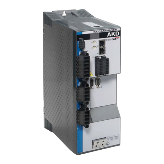
Das CC-Servoverstärkermodell ist mit Feldbussteckern sowohl für EtherCAT (X5 und X6) als auch für CANopen (X12 und X13) ausgestattet. Ein Software-Parameter (DRV.TYPE (S. 651)) erlaubt die Auswahl der vom Servoverstärker unterstützten Merkmale; Sie können EtherCAT und CANopen nicht gleichzeitig verwenden. 2.2 Die AKD-C zentrale Spannungsversorgung Verfügbare AKD Versionen KOLLMORGEN | Mai 2014... - Seite 31 Variante Beschreibung Netz Anschluss AKD-C01007-CBEC Zentrale Spannungsversorgung ohne EtherCAT, Ethernet/IP Erweiterung. AKD-C01007-MCEC Zentrale Spannungsversorgung mit Motion EtherCAT, Ethernet/IP Controller. Umfasst alle fünf EN 61131- Sprachen, PLC Open und Pipes Network. Standardmerkmale Versorgungsspannungsbereich von 400 V bis 480 V ±10%. EMV Netzfilter und 24 V Filter integriert.
- Seite 32 2 STO Status Ausgänge (einer pro Pfad) (➜ S. 1) Service Schnittstelle (➜ S. 1) EtherCAT Schnittstelle (➜ S. 1) Optionskarten MC: Motion Controller mit zusätzlichen digitalen I/O. Erweitert den AKD-C zum AKD-C-PDMM, einem Master für mehrachsige, synchronisierte Systeme. KOLLMORGEN | Mai 2014...
-
Seite 33: Die Digitalen Servoverstärker Der Akd-N Reihe
X18 des intelligenten Netzteils AKD-C. Volldigitale Steuerung Digitaler Stromregler (670 ns) Einstellbarer digitaler Drehzahlregler (62,5 µs) Softwareoption Positionsregler (250 µs) Ein-/Ausgänge 3 programmierbare digitale Eingänge ➜ S. 1 1 programmierbarer digitaler Ausgang ➜ S. 1 Erweiterungen KOLLMORGEN | Mai 2014... - Seite 34 AKD Benutzerhandbuch | 2.3 Die digitalen Servoverstärker der AKD-N Reihe Optionaler Feedback Stecker X5 und lokaler Feldbus Stecker X6, Variante "DF", ➜ p. 1 Optionaler Feedback Stecker X5 und lokaler STO Stecker X6, Variante "DS", ➜ p. 1 KOLLMORGEN | Mai 2014...
- Seite 35 AKD Benutzerhandbuch | 2.3 Die digitalen Servoverstärker der AKD-N Reihe KOLLMORGEN | Mai 2014...
-
Seite 36: Grundlegendes Setup Des Servoverstärkers
AKD Benutzerhandbuch | 3 Grundlegendes Setup des Servoverstärkers 3 Grundlegendes Setup des Servoverstärkers 3.1 Grundlegendes Setup des Servoverstärkers 3.2 Anzeigecodes beim Einschalten 3.3 AKD Setup Assistent KOLLMORGEN | Mai 2014... -
Seite 37: Grundlegendes Setup Des Servoverstärkers
2. Mit Drehschalter S1 und S2 die IP-Adresse des Servoverstärkers festlegen. 3. Den Servoverstärker mit dem Setup-Assistenten konfigurieren. WorkBench Systemvoraussetzungen Erforderliche Komponenten: Microsoft .NET Framework 4.0 Unterstützte Betriebssysteme: Windows XP Windows Vista Windows 7 Windows 8 3.2 Anzeigecodes beim Einschalten KOLLMORGEN | Mai 2014... -
Seite 38: Akdanzeigecodes
StartOperational started reboot. Firmware-Download: fehlerhafte Betriebs-FPGA; Monitor-FPGA ist funktionsfähig. Firmware-Download: HW-Download (HW-Schalter wurde betätigt - Rev. 3 und höher). Firmware-Download: fehlerhafte Betriebs- FW. Firmware-Download: SW-Download (Ausgabe eines Download-Befehls von der Betriebs-FW). Starte Firmware Download Bildladevorgang läuft. KOLLMORGEN | Mai 2014... -
Seite 39: Akd-C Anzeigecodes
AKD-C hat einen Fehler, der nur die Überwachung der Steuerteiltemperatur der AKD-N's deaktiviert. Stränge haben Betriebsspannung und Antriebe arbeiten. Alle AKD-Ns können freigegeben werden. AKD-C hat keinen Fehler und die Stränge haben Betriebsspannung. Fehler (siehe Fehler- und Warnmeldungen) + [3 stelliger Blinkcode] KOLLMORGEN | Mai 2014... -
Seite 40: Akd Setup Assistent
Der Setup-Assistent enthält eine schrittweise Anleitung zur Erstkonfiguration eines Servoverstärkers und zur Ausführungen einer einfachen Testfahrt. Sie können den Setup-Assistenten auf Bildschirmseite Übersicht eines AKD oder AKD-N, oder durch Klicken mit der echten Maustaste auf den Verstärkernamen. KOLLMORGEN | Mai 2014... - Seite 41 System die bevorzugten Einheiten auswählen, Ihre Betriebsart konfigurieren, das System feineinstellen (Tuning) und einfache Tippbewegungen innerhalb des Assistenten ausführen. Wenn die grundlegende Systemkonfiguration Ihren Anforderungen entspricht, können Sie Ihre Einstellungen im Servoverstärker speichern und den Assistenten beenden. KOLLMORGEN | Mai 2014...
-
Seite 42: Anschluss Des Servoverstärkers
4 Anschluss des Servoverstärkers 4.1 Die Stati „Verbindung“ und „Keine Verbindung“ 4.2 Keine Verbindung 4.3 Kommunikation mit dem Servoverstärker bestätigen 4.4 Mit anderem Gerät verbinden 4.5 Konfiguration von TwinCAT und WorkBench 4.6 Behebung von Verbindungs- und Kommunikationsproblemen KOLLMORGEN | Mai 2014... -
Seite 43: Die Stati „Verbindung" Und „Keine Verbindung
Liste mit der MAC-Adresse auf dem Typenschild des Gerätes gegenprüfen. Das Gerät ist angeschlossen, wenn die in WorkBench angezeigten Zahlen mit den Zahlen auf dem Typenschild seitlich am Gerät übereinstimmen. 4.4 Mit anderem Gerät verbinden Klicken auf in der unteren linken Ecke von WorkBench öffnet das folgende Fenster: KOLLMORGEN | Mai 2014... - Seite 44 DNS-Namen eingeben. Sie können auch eine andere Port-Nummer als die Standardnummer (Port 23) angeben, indem Sie sie an die IP-Adresse anhängen (z. B. 1.2.3.4:1000). Discovery Erlaubt die Auswahl von Broadcast Discovery Protokoll oder keinem Discovery Protokoll Protokoll. konfigurieren. KOLLMORGEN | Mai 2014...
-
Seite 45: Konfiguration Von Twincat Und Workbench
Das Installationsverfahren für WorkBench entspricht dem üblichen Verfahren. Ausnahme: WorkBench muss in derselben Maschine installiert werden wie TwinCAT. Die Kommunikation mit dem Servoverstärker erfolgt über den TwinCAT-Master. WorkBench kann nicht dezentral an den Master angeschlossen werden. KOLLMORGEN | Mai 2014... -
Seite 46: Amsnetid Suchen Und Eingeben
4.6 Behebung von Verbindungs- und Kommunikationsproblemen 4.6.1 Gerät nicht angezeigt Wenn Ihr Gerät nicht in der Liste aufgeführt ist, konnte WorkBench das Gerät nicht finden. Nachfolgend sind die häufigsten Gründe für das Nichterscheinen Ihres Gerätes in der Liste aufgeführt: KOLLMORGEN | Mai 2014... -
Seite 47: Ip-Adresse Suchen Und Eingeben
Sie müssten vier Zahlen sehen, die durch insgesamt drei Punkte getrennt sind, z. B. 192.168.1.5. Sie können die IP-Adresse eingeben, wenn Sie auf Mehr klicken und das Feld Adresseangeben aktivieren. 4.6.3 TwinCAT Antrieb nicht angezeigt Wenn kein TwinCAT Gerät angezeigt wird, siehe AmsNetId suchen und eingeben (S. 46) KOLLMORGEN | Mai 2014... -
Seite 48: Kommunikation Mit Dem Akd
AKD Benutzerhandbuch | 5 Kommunikation mit dem AKD 5 Kommunikation mit dem AKD 5.1 Kommunikationsbildschirm 5.2 Konfigurieren der IP-Adresse 5.3 Drehschalter 5.4 Verwendung der SD Karte KOLLMORGEN | Mai 2014... -
Seite 49: Kommunikationsbildschirm
DHCP/AUtoIP wird für die IP Adressierung benutzt wird. 5.1.1.1 TCP/IP Kommunikationsprotokolle IP Adresse Die IP-Adresse eines Servoverstärkers dient zur eindeutigen Kennung im Netzwerk. Ethernet erfordert für jedes Gerät in einem Netzwerksegment eine eindeutige IP-Adresse. KOLLMORGEN | Mai 2014... -
Seite 50: Mac-Adresse
Die Adresse wird nacheinander blinkend auf der Anzeige an der Frontseite eingeblendet. 5.2.2.1 Automatische (dynamische) IP-Adressierung Die automatische Adressierung (auch als „dynamisch“ bezeichnet) verwendet das Dynamic Host Configuration Protocol (DHCP). Das Gerät schalten Sie in DHCP Modus: IP.MODE auf 2 einstellen oder KOLLMORGEN | Mai 2014... -
Seite 51: Statische Ip-Adressierung - Drehschalter
Sie die Spannung aus und wieder einschalten. Dadurch wird die Adresse zurückgesetzt. Für einen erfolgreichen Verbindungsaufbau zwischen Servoverstärker und PC muss die PC- Netzwerkkonfiguration diese Adresse finden. Vergewissern Sie sich zunächst, welchen Netzwerk-Port Sie für die Kommunikation mit dem Servoverstärker nutzen. Anschließend können Sie die Eigenschaften KOLLMORGEN | Mai 2014... -
Seite 52: Geräte Mit Einem Drehschalter
Das Diplay blinkt 0.0.0.0 und dann versucht der Servoverstärker eine Adresse über DHCP zu beziehen. Verwenden Sie, ohne die Spannungsversorgung abzuschalten, WorkBench zurm Verbindungsaufbau, rekonfigurieren Sie die IP Adresse wie gewünscht und speichern Sie die Werte im nichtflüchtigen Speicher. Siehe auch KOLLMORGEN | Mai 2014... -
Seite 53: Drehschalter
Unterschiedliche Funktionen sind in den verschiedenen IP Modi und bei verschiedenen Gerätetypen verfügbar: 5.3.2 Drehschalter-Funktionen in IP.MODE 0 Wenn IP.MODE auf 0 gesetzt ist, wird/werden der/die Drehschalter für statische IP Adressierung benutzt. Siehe Konfigurieren der IP-Adresse (S. 50). KOLLMORGEN | Mai 2014... -
Seite 54: Drehschalter-Funktionen In Ip.mode 0, 1 Oder
Daten von der SD Karte in den Servoverstärker. Stellen Sie sicher, dass eine SD Karte in den Kartenslot gesteckt ist, bevor Sie eine der nachfolgenden Funktionen starten. Beachten Sie, dass der Servoverstärker nur Dateien mit korrektem Dateinamen KOLLMORGEN | Mai 2014... -
Seite 55: Speichern/Laden Im Fenster Parameter Laden/Speichern
Wenn Sie den Computer nicht mit dem Servoverstärker verbinden wollen zum Beschreiben der SD Karte, können Sie auch handelsübliche SD Kartengeräte benutzen, um die Daten und Programme zu speichern. Beachten Sie, dass der Servoverstärker nur Dateien mit korrektem Dateinamen erkennen kann. Nennen Sie das Parameterfile drive.akd und das Programmfile program.bin. KOLLMORGEN | Mai 2014... -
Seite 56: Verwendung Von Workbench
AKD Benutzerhandbuch | 6 Verwendung von WorkBench 6 Verwendung von WorkBench 6.1 Begrüßungsbildschirm 6.2 Online 6.3 Offline 6.4 Geräte Übersicht 6.5 Beobachten 6.6 Einstellungen KOLLMORGEN | Mai 2014... -
Seite 57: Begrüßungsbildschirm
Wenn Ihr Servoverstärker nicht in der Liste erscheint, können Sie seine IP-Adresse (z. B. angeben 1.2.3.4) oder einen DNS-Namen eingeben. Optional können Sie auch eine alternative Port-Nummer anstelle des Standard-Ports (Port 23) angeben. Zum Beispiel würde 1.2.3.4:1000 den Port 1000 definieren. KOLLMORGEN | Mai 2014... -
Seite 58: Offline
Motor anzulegen. Dieser Befehl kann aus verschiedenen Gründen scheitern; siehe "DRV.EN " (➜ S. 604) für weitere Details. Deaktivierung Klicken Sie auf „Deaktivierung“, um die Leistungsstufe DRV.DIS (S. 583) und die am Motor angelegte Spannung auszuschalten. KOLLMORGEN | Mai 2014... -
Seite 59: Online Und Offline
Dieses Textfeld zeigt den Code für die im Servoverstärker DRV.VER (S. 653) ausgeführte Firmwareversion an. Download Klicken Sie auf Download, um die aktuellste AKD Firmware von KOLLMORGEN. Weitere Informationen über Firmware-Downloads finden Sie unter Firmware herunterladen (S. 315) Gesamtbetriebszeit Dieses Textfeld zeigt die Gesamtzeitdauer an, über die DRV.RUNTIME (S. -
Seite 60: Offline-Servoverstärker
AKD-C hat keine Bildschrimseite Einstellungen. Klicken auf Einstellungen führt zur Bildschirmseite Leistung. Für jeden AKD-N in einem AKD-C Strang kann eine Bildschirmseite Einstellungen aufgerufen werden. 6.6.2 Ansicht „Einstellungen“ In der Hauptansicht für die Einstellungen können Sie Folgendes konfigurieren: KOLLMORGEN | Mai 2014... -
Seite 61: Zugehörige Themen
Bewegungs- und Ermöglicht dem Benutzer die Auswahl der Details zu den einzelnen Regelkreisgrafiken Regelkreisen über eine grafische Benutzeroberfläche. Zugehörige Themen Verwendung von Befehlsquellen und Betriebsarten (S. 147) für Details über die Konfiguration des Servoverstärkers für Ihre Anwendung. KOLLMORGEN | Mai 2014... -
Seite 62: Konfiguration Der Verstärkerleistung
AKD Benutzerhandbuch | 7 Konfiguration der Verstärkerleistung 7 Konfiguration der Verstärkerleistung 7.1 Leistung 7.2 Brems-Chopper KOLLMORGEN | Mai 2014... -
Seite 63: Leistung
Servoverstärker kompatibel sein. Sie müssen außerdem Spannungsschwankungen in der DC- Versorgung ober- und unterhalb des Nennwerts berücksichtigen, um Störeinflüsse zu vermeiden. Bei der Ermittlung der maximalen an den Servoverstärker angelegten DC-Nennspannung müssen Sie neben dem Pegel für Überspannung auch den Rückspeisungskreis berücksichtigen. Ein Betrieb des KOLLMORGEN | Mai 2014... - Seite 64 Spannungspegel des verwendeten Servoverstärkers. Nachfolgend sind die Spannungsbereiche aufgeführt: MODELL Pegel für Pegel für Unterspannung Überspannung AKD- 90 VDC 420 VDC zzzz06 AKD- 380 VDC 840 VDC zzzz07 Sie können die Busspannungswerte wie folgt im Bildschirm Leistung anzeigen: KOLLMORGEN | Mai 2014...
-
Seite 65: Brems-Chopper
Rückspeiseleistung Liest die Rückspeiseleistung (nur bei externem REGEN.POWER Bremswiderstand sichtbar). (S. 1055) 7.2.2 Optionen für den Bremswiderstand Wählen Sie "-1 External Regen" in der Box Brems widerstandstyp (REGEN.TYPE (S. 1061)) zum Öffnen der Wähle Widerstand Auswahlliste. KOLLMORGEN | Mai 2014... -
Seite 66: Berechnung Der Motorspitzenenergie Und Der Größe Des Bremswiderstands
Standard-Widerstand verwenden, wählen Sie <Benutzerdefiniert> und geben Sie die entsprechenden Werte für Ihren Bremswiderstand ein. Wenn Sie keinen Standard-Widerstand verwenden, wenden Sie sich an den technischen Kundendienst von KOLLMORGEN, um zu prüfen, dass dieser Widerstand für Ihr System geeignet ist. 7.2.3 Berechnung der Motorspitzenenergie und der Größe des Bremswiderstands Um festzustellen, ob Ihr System einen Bremswiderstand benötigt, müssen Sie die während der... -
Seite 67: Auswahl Eines Kompatiblen Bremswiderstands
Resultate mit den Verstärkerkapazitäten und wählen Sie ggf. aus der Auflistung unten einen externen Bremswiderstand, der diesen Kapazitäten entspricht. Die unten gezeigten Widerstände sind im WorkBench Setup enthalten. Wenn für Ihre Anwendung kein passender Widerstand gelistet ist, wenden Sie sich an den KOLLMORGEN Kundendienst. Widerstandstyp AKD- AKD-... -
Seite 68: Konfiguration Der Parameter Für Den Widerstand
BAFP-100-33 DE-201437 Externer 16,5 Widerstand, 100 W, 33 Ohm BAFP-200-33 DE-201438 Externer 27,5 Widerstand, 200 W, 33 Ohm BAR-250-33 DE-106254 Externer 22,0 Widerstand, 250 W, 33 Ohm BAR-500-33 DE-106255 Externer 33,0 Widerstand, 500 W, 33 Ohm KOLLMORGEN | Mai 2014... -
Seite 69: Zugehörige Parameter
Widerstand, 2000 W, 15 Ohm BAS-3000-15 DE-103872 Externer 84,3 3000 Widerstand, 3000 W, 15 Ohm BAS-6000-15 DE-103873 Externer 91,7 6000 Widerstand, 6.000 W, 15 Ohm Zugehörige Parameter REGEN Parameters (S. 1054) VBUS.OVWTHRESH (S. 1134) VBUS.VALUE (S. 1139) KOLLMORGEN | Mai 2014... -
Seite 70: Konfiguration Der Motoreinstellungen
AKD Benutzerhandbuch | 8 Konfiguration der Motoreinstellungen 8 Konfiguration der Motoreinstellungen 8.1 Motor 8.2 Rückführung 1 8.3 Rückführung 2 8.4 Rückführgeräte ohne Plug & Play 8.5 Foldback 8.6 Motor Haltebremse KOLLMORGEN | Mai 2014... -
Seite 71: Motor
8.1.2 Motor-Setup Wenn die automatische Motoreinstellung angewählt ist (MOTOR.AUTOSET = 1), konfiguriert der AKD die Motorparameter automatisch mit den im Feedback gespeicherten Daten (KOLLMORGEN Motoren mit SFD, EnDat, BiSS , Hiperface und Hiperface DSL). Bei automatischer Erkennung des Motors sind die Parameter auf der Bildschirmseite Motor ausgegraut und nicht zugänglich. -
Seite 72: Auswahl Eines Motors
Wird diese Bildschirmseite geöffnet, zeigt WorkBench standardmäßig den Motor an, der dem Namen des derzeit an den Servoverstärker angeschlossenen Motors entspricht. WorkBench sucht wie folgt nach dem passenden Motor: 1. WorkBench prüft zunächst den Motornamen auf Übereinstimmung mit kundenspezifischen Motoren. KOLLMORGEN | Mai 2014... -
Seite 73: Konfiguration Kundenspezifischer Motoren
3. Wird keine Übereinstimmung gefunden, erfolgt die Auswahl eines AKM-Motors. Für Motoren, die keine Plug & Play-Motoren sind, ist eine Datenbank mit Katalogmotoren auf Basis der verschiedenen Motorbaureihen von KOLLMORGEN verfügbar. Wenn Sie eine Motorbaureihe wählen, erscheint eine entsprechende Teilenummer. Sie können die Teilenummer nach Bedarf ändern. Je nach getroffener Auswahl wird der vollständige Motorname angezeigt. -
Seite 74: Validierung Von Motorparametern
Wenn beim Einstellen der Motorparameter ein Fehler auftritt, zeigt ein Fehlerbildschirm an, welche Parameter einer Überprüfung bedürfen. 8.1.6 Motor Derating Motor Derating (Leistungsbegrenzung) bei AKM oder VLM Motorserien. Wenn eine Motorhaltebremse oder ein anderes Feedback als Resolver gewählt wird, wird der Dauerstrom begrenzt. Resolver ohne Bremse (keine Begrenzung): KOLLMORGEN | Mai 2014... - Seite 75 AKD Benutzerhandbuch | 8.1.6 Motor Derating SFD ohne Bremse (Begrenzung): KOLLMORGEN | Mai 2014...
-
Seite 76: Motor Temperatur
Feedbacktypen gelistet. In der Modellbezeichnung Ihres Motors ist die Art des Rückführsystems kodiert. KOLLMORGEN Motoren mit digitalem Feedback (SFD, Endat, BiSS und Hiperface, Tamagawa) sind Plug-and-Play fähig. Bei diesen Motoren werden alle Feedback und Motordaten automatisch konfiguriert. Bei Motoren von Fremdanbietern oder Motoren mit anderen Feedbacksystemen müssen die Parameter manuell eingetragen werden. -
Seite 77: Verwendung Der Feedback Optionen
Diese Feedbackgeräte sind Plug&Play-Geräte, wenn Sie als AKM Motoroption bestellt wurden. 8.2.2.6 BiSS Analog Diese Feedbackgeräte sind Plug&Play-Geräte, wenn Sie als AKM Motoroption bestellt wurden. 8.2.2.7 Hiperface, Hiperface DSL Diese Feedbackgeräte sind Plug&Play-Geräte, wenn Sie als AKM Motoroption bestellt wurden. KOLLMORGEN | Mai 2014... -
Seite 78: Resolver
Feedback Polzahl. Zurzeit unterstützt der AKD nur die Standard-Resolver-Optionen von KOLLMORGEN. 8.2.2.9 SFD, SFD3 Smart Feedback Device (SFD) ist das Plug-and-Play-Gerät von KOLLMORGEN. SFD ermöglicht die schnelle und einfache Konfiguration im Modus Auto, der den Verstärker automatisch mit den Rückführungs- und Motorparametern konfiguriert. -
Seite 79: Verwendung Von Wake & Shake Mode 0 (Ws.mode 0)
Regelkreise stabil sein. Eine im Servoverstärker vorhandene Datenbank enthält die Kompensationswerte für zahlreiche Rotationsmotoren. Ein instabiles System funktioniert weder während noch nach dem WS-Prozess einwandfrei. Verwenden Sie die standardmäßige Wake & Shake-Bildschirmseite zur Konfiguration Ihres Systems: KOLLMORGEN | Mai 2014... -
Seite 80: Wake & Shake, Bildschirm Mehr
Initialisierung infolge von Drahtbruch, falschen Stromeinstellungen, sehr hoher Reibung usw. Durch Nullsetzen von WS.DISTMIN wird diese Funktion deaktiviert. Wake & Shake, Bildschirm Mehr Um weitere WS Einstellungen zu konfigurieren, klicken Sie auf Mehr unten im Fenster. Es erscheinen die folgenden Optionen: KOLLMORGEN | Mai 2014... -
Seite 81: Sonderfälle Für Ws
2. Wenn der Motor einen Endschalter betätigt, kann das System (PLC, SWLS.LIMIT0 und SWLS.LIMIT1) eventuell den AKD hindern, eine Bewegung des Motors zu erzeugen. Wenn keine deskriptive Bewegung erzielt wird, tritt ein Systemfehler auf. System mit hoher Lastträgheit oder Reibung KOLLMORGEN | Mai 2014... -
Seite 82: Verwendung Von Ws: Erweitert
Sie mit Hilfe der Parameter für Geschwindigkeits-/Drehzahlüberschreitung (WS.VTHRESH und DRV.VTHRESH) einen Stabilitätsverlust verhindern. Setzen Sie vor Freigabe des Servoverstärkers der Parameter DRV.VTHRESH auf 100 mm/s für Linearmotoren bzw. auf 200 U/Min für Rotationsmotoren. Nach erfolgreicher Freigabe können Sie KOLLMORGEN | Mai 2014... -
Seite 83: Fehlersuche Und -Behebung Bei Ws
Stabilität beeinträchtigen. Setzen Sie WS.NUMLOOPS = 20. Fehlersuche und -behebung bei WS Problem Mögliche Ursache Maßnahmen Zu große Bewegung Bremse rutscht bei vertikaler Bremse prüfen. Achse. Auf Motor wirkende Kräfte Einwirken zu großer externer eliminieren. Kräfte auf den Motor. WS.IMAX verringern. KOLLMORGEN | Mai 2014... - Seite 84 (WS.DISARM) oder ist fehlgeschlagen. Andere Servoverstärker nicht korrekt Kompensation des konfiguriert. Servoverstärkers prüfen. Servoverstärker-Rückführung prüfen. Zugehörige Parameter WS Parameters (S. 1181) DRV.IPEAK (S. 624) FB1.SELECT (S. 709) MOTOR.BRAKE (S. 889) MOTOR.PHASE (S. 914) MOTOR.IPEAK (S. 905) KOLLMORGEN | Mai 2014...
-
Seite 85: Verwendung Von Wake & Shake Mode 1 (Ws.mode 1)
In der Ansicht „Rückführung 2“ können Sie konfigurieren, ob Anschluss X9 oder X7 verwendet wird. Der Bildschirm verwendet den Begriff der Rückführung, Sie können ihn aber auch als Signalquelle auffassen, je nachdem, wie Sie diese Anschlusspunkte verwenden. Im Feld Rückführungsquelle können Sie aus drei Quellen für die Rückführung wählen: KOLLMORGEN | Mai 2014... -
Seite 86: Encoder-Emulation
Anschlussfunktion, die Auflösung und (sofern zutreffend) die Eingangsposition festlegen. Der Bildschirm Elektronisches Getriebe ermöglicht auch die Einstellung der Funktion von Anschluss X9. 8.3.1.3 Funktionseinstellungen Die Zuweisung der Funktionseinstellungen für Anschluss X9 erfolgt über den Parameter DRV.EMUEMODE (S. 595). Emulations-Modus KOLLMORGEN | Mai 2014... -
Seite 87: Ausgangsmodi 1, 2, 6, 7, 8 Und
Modus 6 – Ausgang – mit Indeximpuls pro Umdrehung und Eingang – Schritt und Richtung In diesem Modus können Sie emulierte Puls/Richtung Encoder-Signale über Anschluss X9 (Emulierter Encoder) ausgeben und gleichzeitig ein Drehschalter-Schrittsignal über Anschluss X7 (Hochgeschwindigkeits-Optokoppler-EA) einlesen. Modus 6 und 7 sind identisch, mit dem einzigen KOLLMORGEN | Mai 2014... -
Seite 88: Eingangsmodi 3, 4 Und 5 (Veraltet)
Drittanbieters. Die Schrittzahl kann eingestellt werden, so dass der Servoverstärker mit jeder Schrittmotorsteuerung arbeiten kann. Modus 5-CW/CCW-Signale Eingangsmodus 5 – CW/CCW-Signale – Anschlussbild Der Verstärker kann an einen Controller eines Drittanbieters angeschlossen werden, der Up/Down- Signale liefert. KOLLMORGEN | Mai 2014... -
Seite 89: Modus 10, Konfiguriert X9 Für Allgemeine E/A
(DIO 9, 10, 11). DIOx.DIR konfiguriert die Übertrager als Ein- oder Ausgänge. DIOx.INV steuert die Polarität dieser Signale. 8.3.1.7 Modus 11, konfiguriert X9 für Endat 2.2 Dieser Modus ermöglicht den Anschluss eines Heidenhain Endat 2.2 Encoders an X9. Dieser Encoder kann als primäres Feedback oder als Drehschalter-Schrittsignal Eingang benutzt werden. KOLLMORGEN | Mai 2014... -
Seite 90: Ausgangs Modi 12, 13, Und 14, Emulierter Encoder Mit Durchgeschleiftem Z Signal
Eingang konfiguriert ist). Bei der Auflösung handelt es sich um eine Post-Quadratur.Beispiel: Ein 1.000-Schritt-Encoder hat eine Auflösung von 4.000 Schritten. Hinweis: Wenn der Wert für die Auflösung auf gesetzt ist, erzeugt Anschluss X9 keinen Befehl. KOLLMORGEN | Mai 2014... -
Seite 91: Zugehörige Parameter Und Befehle
Übergangsfrequenz/Bandbreite (BW) bei geschlossenem Regelkreis nominal unter 2000 Hz oder (PWM- Frequenz/4) liegt. Setzen Sie diese Frequenz wie folgt in die Gleichung ein: IL.KP = 2*π*(gewünschte Bandbreite in Hz)*(Motorinduktivität (L) zwischen Phasen in Hz) Einstellen der D und Q Komponenten KOLLMORGEN | Mai 2014... -
Seite 92: Geschwindigkeitsregler
Strom wieder über DRV.ICONT steigen kann, ist eine Erholungszeit erforderlich, während derer der Strom unter DRV.ICONT liegt. Eine Erholungszeit von IL.DFOLDR mit Nullstrom ermöglicht dem Verstärker das Anlegen von Strom in Höhe von DRV.IPEAK über die Zeitdauer IL.DFOLDD. KOLLMORGEN | Mai 2014... -
Seite 93: Konfiguration Des Motor-Foldback
8.5.4 Motorspitzenstrom-Zeit Der Spitzenstrom (MOTOR.IPEAK) wird gemeinsam mit der thermischen Spulenkonstante (MOTOR.CTFO) verwendet, um den maximalen Zeitraum zu ermitteln, über den der Motor Spitzenstrom handhaben kann. Der maximale Zeitraum (IL.MFOLDD) wird wie folgt im Foldback-Bildschirm angezeigt: KOLLMORGEN | Mai 2014... -
Seite 94: Motor-Foldback-Rampe
Nullstrom ist erforderlich, damit der Motor in kürzester Zeit seine volle Leistungsfähigkeit erreicht. Der Servoverstärker kann den Strom auf einen Wert unterhalb des Dauerstroms einregeln, um die Last weiter anzutreiben, allerdings erhöht sich so die Erholungszeit für das Erreichen der maximalen Leistungsfähigkeit. KOLLMORGEN | Mai 2014... -
Seite 95: Gesamt-Foldback
Die Betätigung und das Lösen der Bremse erfolgen je nach Status der Funktion Servoverstärker aktiv. Sie können die Verzögerungen für das Lösen und Betätigen der Bremse mit Hilfe der unten aufgeführten Parameter ändern. Schaltfläche bzw. Beschreibung Parameter Dialogfenster Bremsensteuerung Einstellung ob Motorbremse MOTOR.BRAKE vorhanden ist. KOLLMORGEN | Mai 2014... - Seite 96 Die vom Nutzer einstellbare Zeit, die MOTOR.TBRAKERLS die Bremse mechanisch zum Öffnen benötigt. Nach dieser Zeit werden Fahrbefehle akzeptiert. Anzugszeit Die vom Nutzer einstellbare Zeit, die MOTOR.TBRAKEAPP die Bremse mechanisch zum Schließen benötigt. Nach dieser Zeit wird der Antrieb gesperrt. KOLLMORGEN | Mai 2014...
- Seite 97 Diese Seite wurde bewusst leer gelassen. KOLLMORGEN | Mai 2014...
-
Seite 98: Verwendung Der Positionserfassung
Wählen Sie zur Konfiguration der Positionserfassung die aus der Gruppe Einstellungen die Option Positionserfassung: Einstellen der Erfassungsquelle (CAP0.FBSOURCE, CAP1.FBSOURCE (S. 485)) CAP0.FBSOURCE und CAP1.FBSOURCE wählen die Quelle des Erfassungswertes. Daten für allen Quellen finden Sie wieder mit CAP0.PLFB, CAP1.PLFB (S. 489). KOLLMORGEN | Mai 2014... -
Seite 99: Einstellen Der Triggerquelle (Cap0.Trigger, Cap1.Trigger (S. 1))
Einstellung der Erfassungsflanke (CAP0.EDGE, CAP1.EDGE (S. 478)) Die Erfassungsflanke bestimmt, welche Änderung des Eingangsstatus die Erfassung auslöst. Optionen für die Erfassungsflanke: Option Beschreibung 1 – Steigende Flanke. Löst eine Erfassung aus, wenn das Eingangssignal von Low auf High wechselt. KOLLMORGEN | Mai 2014... -
Seite 100: Einstellen Des Vorbedingungs-Ereignisses: (Cap0.Event, Cap1.Event (S. 1))
Die Vorauswahl legt fest, welche Eingangsquelle die Vorbedingung auslöst (basierend auf den Einstellungen für Vorflanke und Vorfilter). Die Funktionsweise dieser Option ist mit derjenigen der oben beschriebenen Erfassungsquelle identisch. 8.7.3 KOLLMORGEN Testberichte Positionerfassung Testbericht basierend auf Leistungstest durch KOLLMORGEN: Capture Accuracy with External Sensor Drive: AKD-T00306-NBAN-000 Motor: AKM-21C... -
Seite 101: Zugehörige Parameter
AKD Benutzerhandbuch | 8.7.3 KOLLMORGEN Testberichte With the motor running at above speed and the capture mechanism armed, the drive was able to capture the position within 10-20 counts (.05 - .11 degree) of accuracy or 9.5 – 18.0 micro sec. -
Seite 102: Verwendung Von Akd In Vertikalen Achsen
Verstärker die Bremse sofort an und versucht gleichzeitig, der normalen Disable Prozedure zu folgen. Der Wert ist begrenzt auf maximal 167 ms. Während dieser Zeit versucht der Verstärker, die Last auf Geschwindigkeit 0 zu verzögern. Wenn DRV.HWENDELAY = 0, ist die Funktion abgeschaltet (standard). KOLLMORGEN | Mai 2014... - Seite 103 Endstufe nicht sperren oder andere .CS.TO Wenn nicht Sperrkommandos geben, bis CS möglich, Fehler CS durchgeführt wurde und die Bremse dynamische geschlossen ist. Bremsung. Fehler Dynamische – – Bremse Fehler Endstufe none MOTOR.BRAKEIMM = 1 gesperrt KOLLMORGEN | Mai 2014...
-
Seite 104: Konfiguration Mit Linearmotoren
„0 – Aus“ gesetzt werden, um die Option zu aktivieren. Auf der Bildschrimseite "Motor wählen", wählen Sie antweder die Motorfamilie IC und ICD Series Ironcore DDL oder IL Series Ironless DDL. Im Bildschirm „Motor wählen“ unter „Name“ die entsprechende Motorteilenummer wählen. KOLLMORGEN | Mai 2014... - Seite 105 Bildschirmseite "Feedback 1" in WorkBench. Wenn die Spulenbaugruppe in Richtung des Kabelausgangs bewegt wird (z. B. durch Ziehen am Spulenkabel), müsste der Wert der Positionsrückführung positiv steigen, und der graue Block in der Motorgrafik müsste sich nach rechts bewegen. Bei entgegengesetzter KOLLMORGEN | Mai 2014...
- Seite 106 AKD Benutzerhandbuch | 10.1 Anschluss eines DDL-Motors an einen AKD Servoverstärker Richtung müssen die Signale A+ und A- an der Linearskala vertauscht werden, um die Phasendrehrichtung zu korrigieren. Der Motor ist jetzt für die Kompensation von Geschwindigkeits- und Positionsregelkreis bereit. KOLLMORGEN | Mai 2014...
-
Seite 107: Auswählen Von Einheiten Für Ihre Anwendung
AKD Benutzerhandbuch | 11 Auswählen von Einheiten für Ihre Anwendung 11 Auswählen von Einheiten für Ihre Anwendung 11.1 Auswählen und Speichern von Einheiten 11.2 Beispiel 11.3 Benutzereinheiten mit Feedback 2 nutzen KOLLMORGEN | Mai 2014... -
Seite 108: Auswählen Und Speichern Von Einheiten
4 – Schritte (16 Bit) (65.536 /U) Benutzerspezifische Einheiten Der Servoverstärker verwendet unabhängig von den Einstellungen für die Einheiten eine volle 32-Bit- Quantisierung für interne Berechnungen. Benutzerspezifische Einstellungen für die Einheiten haben keine Auswirkungen auf die Leistung, Auflösung oder Genauigkeit des Servosystems. KOLLMORGEN | Mai 2014... - Seite 109 Sie können UNIT.PIN und UNIT.POUT direkt unter Nur Motor im Feld Typ der Mechanik wählen eingeben. In diesem Beispiel wird die Skalierung wie folgt angepasst: UNIT.PIN wird wie folgt berechnet: 10 mm/Spindeldrehung * 1 Spindeldrehung/5 Motordrehungen = 2 mm/Motordrehung KOLLMORGEN | Mai 2014...
-
Seite 110: Benutzereinheiten Mit Feedback 2 Nutzen
AKD Lageregelkreis). Der Encoder ist auf einer runden Scheibe mit 400mm Umfang montiert. Eine Umdrehung des Encoders soll 400mm entsprechen. In diesem Fall, setzen Sie UNIT.PIN auf 400 und UNIT.POUT auf 1. Zugehörige Parameter UNIT Parameters (S. 1109) DRV.NVSAVE (S. 638) MOTOR.TYPE (S. 934) KOLLMORGEN | Mai 2014... -
Seite 111: Konfiguration Der Allgemeinen Servoverstärker-Einstellungen
12.1 Digitale Eingänge und Ausgänge 12.2 Befehls-Buffer 12.3 Analogeingang 12.4 Analogausgang 12.5 Elektronisches Getriebe 12.6 Grenzwerte 12.7 Programmierbarer Endschalter 12.8 Freigabe/Deaktivierung 12.9 Kontrollierter Stopp 12.10 Dynamisches Bremsen 12.11 Not-Halt 12.12 Safe Torque Off (STO) 12.13 Verhalten bei Unterspannungsfehler KOLLMORGEN | Mai 2014... -
Seite 112: Digitale Eingänge Und Ausgänge
Änderungen an diesem Eingang ignoriert. Beispiel: -->DIN1.MODE 2 - Setzt den Eingangsmodus auf Fahrauftrag starten. -->DIN1.PARAM 1 - Legt fest, dass der zu startende Fahrauftrag 1 ist. -->MT.LIST - Stellt sicher, dass der Fahrauftrag 1 existiert. KOLLMORGEN | Mai 2014... - Seite 113 Modus 9: Befehlspuffer Dieser Modus dient zur Ausführung vier verschiedener Befehlspuffer-Sätze. Jeder Satz enthält zwei Puffer: Low und High, für insgesamt acht Puffer. DINx.PARAM für diesen Modus kann 1 bis 4 lauten und bestimmt, welcher Puffersatz verwendet wird. KOLLMORGEN | Mai 2014...
- Seite 114 Variable wird durch DINx.PARAM festgelegt. Der Parameter wird in Positionseinheiten angegeben und wird verwendet, um eine Phasenverschiebung während des Betriebs im elektronischen Getriebemodus hinzuzufügen. Dieser Modus ist für Betriebsart 2 (Position) und Befehlsquelle 2 (elektronisches Getriebe) gültig. Beispiel KOLLMORGEN | Mai 2014...
- Seite 115 Screenshot unten zeigt die aktuelle, für den Servoverstärker eingestellte Befehlsquelle/Betriebsart an. Der Servoverstärker befindet sich in diesem Modus, wenn der Digitaleingang nicht auf High gesetzt ist. Dieser Low-Status wird durch die ursprünglichen Einstellungen für DRV.CMDSOURCE und DRV.OPMODE bestimmt. KOLLMORGEN | Mai 2014...
- Seite 116 Eingang kombinierte Kombination aus Sollwertquelle/Betriebsart aktiv. Wenn zusätzliche Eingänge aktiv werden, dann ist die für den Eingang mit der niedrigsten Nummer konfigurierte Kombination aus Befehlsquelle/Betriebsart aktiv. Beispiel Setzen Sie voraus: Eingang 1 ist für elektronisches Getriebe/Position konfiguriert. Eingang 2 ist für Service/Geschwindigkeit konfiguriert. KOLLMORGEN | Mai 2014...
- Seite 117 Multiplikation der Analogspannung mit -1 und zusätzliches Auslösen eines Software-Enable. 0x06 Nullsetzen der gemessenen Analogspannung und zusätzliches Auslösen eines Software-Disable. 0x07 Multiplikation der Analogspannung mit 1 und zusätzliches Auslösen eines Software-Disable. 0x08 Multiplikation der Analogspannung mit -1 und zusätzliches Auslösen eines Software-Disable. KOLLMORGEN | Mai 2014...
-
Seite 118: Digitalausgänge
Überspannungsfehler liegt. Dieser Modus ist gültig für alle Kombinationen aus Betriebsart und Sollwertquelle. Modus 2-Software-Grenze: Dieser Ausgang wird bei Erreichen der Software-Grenzpositionen aktiviert. Dieser Ausgang erzeugt ein High-Signal, wenn eine Software-Grenze durch Bewegung in Richtung dieser KOLLMORGEN | Mai 2014... - Seite 119 Dieser Modus ist nur für Betriebsart 2 (Position) und Sollwertquelle 0 (Service) gültig. Modus 15- PLS.STATE Bits ODER verbunden: Der Ausgang wird aktiviert, wenn mindestens eines der PLS.STATE Bits auf High gesetzt ist (PLS ist aktiv) und das entsprechende Bit im Parameter KOLLMORGEN | Mai 2014...
- Seite 120 Dieser Ausgangsmodus erzeugt ein High-Signal, wenn das Einschaltrelais geschlossen ist. Übersicht über die Abhängigkeiten von Betriebsart und Sollwertquelle DINx.MODE Modusbeschreibung OPMODE Befehlsquelle alle alle Fehler-Reset alle alle Starte Motion Task 2-Position 0-Service Motion Task Auswahlbit 2-Position 0-Service Motion Task Auswahl Start 2-Position 0-Service KOLLMORGEN | Mai 2014...
- Seite 121 Abs. Geschwindigkeit < x alle alle Referenzfahrt beendet 2-Position 0-Service Programmierbarer Endschalter alle alle Befehlspuffer aktiv alle alle Fahrauftrag in Position Kontrollierter Stopp Aktiv alle alle Sofortige Sperre nach Fehler. alle alle Status Einschaltrelais alle alle KOLLMORGEN | Mai 2014...
-
Seite 122: Digitale Eingänge (X7/X8)
Wenn ein Eingang programmiert wurde, muss dies im Verstärker gespeichert werden. Je nach der ausgewählten Funktion sind die Eingänge HIGH oder LOW aktiv. Die Eingänge können mit geschalteten +24 V ("Source") oder geschaltetem GND ("Sink") verwendet werden. Siehe folgende Diagramme. Anschlussbild (Anschluss Typ "Source", Beispiel) KOLLMORGEN | Mai 2014... - Seite 123 AKD Benutzerhandbuch | 12.1.5 Digitale Eingänge (X7/X8) Anschlussbild (Anschluss Typ "Sink", Beispiel) KOLLMORGEN | Mai 2014...
-
Seite 124: Digitale Eingänge 1 Und
X8/4, aktiv high). Die Freigabe ist nur möglich, wenn am STO Eingang ein 24 V-Signal anliegt . Im deaktivierten Status (Low Signal) erzeugt der angeschlossene Motor kein Drehmoment. Eine Software-Freigabe durch die Setup-Software ist ebenfalls erforderlich (UND-Verknüpfung). Die Software Freigabe in WorkBench kann auf permanent gesetzt werden. KOLLMORGEN | Mai 2014... -
Seite 125: Optionskarte I/Os
Parameter unter Verwendung eines Digitaleingangs ändern. Der Servoverstärker verfügt über vier Befehlspuffer. Ein für den Befehlpuffer-Modus konfigurierter Digitaleingang ist mit einem Befehlspuffersatz verknüpft. Dies wird durch den Benutzer festgelegt (siehe Pfeil 1). In diesem Fall wird Befehlspuffer 1 verwendet. KOLLMORGEN | Mai 2014... -
Seite 126: Bearbeitung Der Befehlspuffer
Maus über das Feld Param fahren, zeigt der Tooltipp den aktuellen Inhalt des „Low“- und des „High“- Befehlspuffers im Servoverstärker an. Klicken Sie zum Bearbeiten des gewählten Befehlsspeichers auf Bearbeiten. Daraufhin erscheint der Bildschirm des Befehlspuffer-Editors. KOLLMORGEN | Mai 2014... - Seite 127 Meldung: „Die Befehle wurden geändert und nicht im Servoverstärker gespeichert. Möchten Sie ohne Speicherung der Änderungen schließen?“. Befehle und Parameter werden in separate Zeilen eingegeben.Zwischen Parameter und Wert wird ein Leerzeichen gesetzt. KOLLMORGEN | Mai 2014...
-
Seite 128: Verhalten Des Befehlspuffers
Bei Betriebsart „Geschwindigkeit“ ist dieser Wert die 412) Geschwindigkeit pro 1 Volt am Analogeingang. Hinweis: Die Skalierung in KAS beträgt 80% der Skalierung im AKD. Im AKD sind 10 V = 32767 jedoch in KAS 10 V = 26126 KOLLMORGEN | Mai 2014... -
Seite 129: Zugehörige Parameter
Analogausgang (S. 436) Tiefpass-Filter Aktiviert einen Software-basierten Tiefpass-Fillter des analogen AOUT.CUTOFF Ausgangswert. 0 Hz deaktiviert diese Funktion. (S. 428) Die analogen Ausgangsmodi umfassen: AOUT.MODE Beschreibung Benutzervariable. Das analoge Ausgangssignal wird vom Benutzer festgelegt (mithilfe von AOUT.VALUEU). KOLLMORGEN | Mai 2014... -
Seite 130: Elektronisches Getriebe
Zur Steuerung eines AKD mit elektronischem Getriebe muss die Sollwertquelle (DRV.CMDSOURCE) auf 2-Elektronisches Getriebe und die Betriebsart (DRV.OPMODE) auf 2-Position Mode gesetzt sein. Die Eingangsmodi von Stecker X9 dienen zur Konfiguration des AKD für die Nutzung des elektronischen Getriebes. KOLLMORGEN | Mai 2014... -
Seite 131: Grenzen
Bei der Geschwindigkeitsabstimmung beschleunigt der Motor auf dieselbe Geschwindigkeit, ungeachtet jeglicher Schrittverluste während der Beschleunigungsperiode. Bei der Positionsabstimmung stimmt der Motor den Positionsbefehl vom Übergangspunkt ab, indem er beschleunigt, um die während der Beschleunigungsphase verlorenen Schritte aufzuholen. KOLLMORGEN | Mai 2014... -
Seite 132: Ermittlung Der Maximalen Kabellänge
Maximal zulässige Kabellänge für die Beispielanwendung = 26,9 m = (Maximaler Kabelwiderstand) 5 Ohm ÷ 0,186 Ohm/m Zugehörige Parameter GEAR Parameters (S. 761) DRV.CMDSOURCE (S. 573) DRV.EMUEMODE (S. 595) DRV.EMUERES (S. 601) DRV.HANDWHEEL (S. 612) DRV.OPMODE (S. 640) KOLLMORGEN | Mai 2014... -
Seite 133: Grenzwerte
Servoverstärkers. Sie können diese Grenzwerte auf Werte unterhalb der Vorgabewerte einstellen, allerdings kann dies die erwartete Leistungsfähigkeit Ihrer Anwendung beeinträchtigen. Geschwindigkeits-Grenzwerte: Die Geschwindigkeits-Grenzwerte basieren auf den Bemessungsdaten des Motors. Sie können diese Grenzwerte auf Werte oberhalb der KOLLMORGEN | Mai 2014... -
Seite 134: Programmierbarer Endschalter
3. Der digitale Ausgangsmodus ist jetzt für PLS eingestellt.Klicken Sie auf den Link Gehe zu programmierbarem Endschalter (siehe 2 unten), um den PLS-Bildschirm zu öffnen (dieser Bildschirm ist auch in der Baumansicht von WorkBench aufgeführt). Der PLS-Bildschirm dient zur Festlegung der Einschaltpositionen für den bzw. die Ausgänge. KOLLMORGEN | Mai 2014... - Seite 135 PLS.STATE Bits mit dem Digitalausgang selbst und fungiert somit als Freigabemaske. Das Gate ist im Bildschirm konfigurierbar, wenn ein digitaler Ausgang auf Modus 15 – Progr.Endschalter-Status gesetzt ist. Da nur PLS1 konfiguriert ist, wählen Sie PLS 1 (siehe Pfeil oben). KOLLMORGEN | Mai 2014...
-
Seite 136: Single Shot-Modus
Der Single Shot-Modus (Einzelschussmodus) ist ein spezieller PLS-Modus. Der Single Shot-Modus (siehe 1 unten) schaltet den Ausgang ein, bis er zurückgesetzt wird (siehe 2 unten). Der Normalbetrieb dieses Modus ist in der Regel davon abhängig, dass eine Maschinensteuerung den PLS mit dem Feldusobjekt für PLS.RESET zurücksetzt. KOLLMORGEN | Mai 2014... -
Seite 137: Freigabe/Deaktivierung
Drehmomentabschaltung (Safe Torque Off, STO) und deckt auf diese Weise verschiedenste Bedingungen ab. Hardware-Freigabemodus: Der AKD bietet zwei Methoden zur Hardware Freigabe. Die Auswahl der Methode erfolgt über DRV.HWENMODE. Modus 0 ermöglicht die Freigabe des Servoverstärkers und das Löschen von KOLLMORGEN | Mai 2014... -
Seite 138: Vorgabe Für Software-Freigabe
Deaktivierungsmodus folgt, bevor er deaktiviert wird. Dies erfolgt unabhängig von der gewählten Methode und etwaigen Warnungen wegen eines Emergency-Timeout-Fehlers. Die Ausführung sämtlicher Deaktivierungsmodi ist von der Art des empfangenen Deaktivierungsbefehls abhängig. Kritische Fehler, eine Hardware-Deaktivierung oder STO führen zum unverzüglichen KOLLMORGEN | Mai 2014... -
Seite 139: Servoverstärker-Status
Die Mehr-Schaltfläche dient zur Anzeige des Statusdiagramms für die Konfiguration des kontrollierten Stopps. Sie zeigt außerdem das Blockschaltbild für den kontrollierten Stopp an. Es sind zwei Blockschaltbilder verfügbar: eines mit montierter Bremse und eines ohne Bremse. KOLLMORGEN | Mai 2014... -
Seite 140: Kontrollierter Stopp
Eine Steuerung bzw. der Benutzer (über das WorkBenchTerminal-Fenster) initiiert einen Befehl zur Deaktivierung der Software (DRV.DIS). Der CANopen PDO wird auf 3442 gesetzt. CANopen Eigenschaft Wert Index/Subindex 3442/0 Datentyp Unsigned 8 Zugriff PDO mappable Beschreibung Kontrollierter Stopp ASCII Objekt KOLLMORGEN | Mai 2014... - Seite 141 Wenn das in Schritt eingestellte Zeitfenster für Nulldrehzahl (VEL0) zu klein ist, erreicht der Servoverstärker möglicherweise niemals das Ende des kontrollierten Stoppprozesses. In diesem Fall kann der Servoverstärker nach Ablauf von DRV.DISTO deaktiviert werden, selbst dann, wenn der kontrollierte Stopp nicht abgeschlossen ist. Diagramm für kontrollierten Stopp KOLLMORGEN | Mai 2014...
-
Seite 142: Zugehörige Parameter Und Befehle
Stopp. 1 = Es erfolgt ein kontrollierter Stopp). DIN1.MODE TO DIN7.MODE (S. 525) DRV.DIS (S. 583) DRV.DISTO (S. 591) DRV.DISMODE (S. 585) Zugehörige Themen: Not-Halt (S. 143) Digitale Eingänge und Ausgänge (S. 112) Fehler und Warnmeldungen (S. 273) KOLLMORGEN | Mai 2014... -
Seite 143: Dynamisches Bremsen
Widerstands für den Fall, dass eine höhere Leistung benötigt wird. Zugehörige Themen Ausführliche Informationen zu diesem Thema finden Sie in Abschnitt 6.14 Dynamische Bremsung in der AKDBetriebsanleitung. DRV.DISMODE (S. 585) DRV.DBILIMIT (S. 576) 12.11 Not-Halt KOLLMORGEN | Mai 2014... -
Seite 144: Stopp/Not-Halt/ Not-Aus
Stopp der Kategorie 0 Priorität besitzen muss. Bei Bedarf sind Vorkehrungen für den Anschluss von Schutzvorrichtungen und Verriegelungen zu treffen. Falls notwendig, muss die Stopp-Funktion ihren Status an die Steuerlogik melden. Ein Zurücksetzen der Stopp-Funktion darf nicht zu einer Gefahrensituation führen. KOLLMORGEN | Mai 2014... -
Seite 145: Not-Halt
Not-Aus wird erreicht durch Abschalten der Energieeinspeisung mit elektromechanischen Schaltgeräten. Das führt zu einem Stopp der Kategorie 0. Wenn diese Stopp Kategorie für die Maschine nicht zulässig ist, muss der Not-Aus durch andere Maßnahmen (z.B. Schutz gegen direktes Berühren) ersetzt werden. KOLLMORGEN | Mai 2014... -
Seite 146: Safe Torque Off (Sto)
Wenn ein Unterspannungsfehler auftritt, wird der Servoverstärker deaktiviert und es werden folgende Warnungen ausgegeben: WorkBench Warnung: 502 Unterspannung Bus Warnung der LEDs am Servoverstärker: Linke LED zeigt [F] an, rechte LED zeigt [u-V] an. Der Fehlerrelaisausgang wird eingeschaltet. KOLLMORGEN | Mai 2014... -
Seite 147: Verwendung Von Befehlsquellen Und Betriebsarten
AKD Benutzerhandbuch | 13 Verwendung von Befehlsquellen und Betriebsarten 13 Verwendung von Befehlsquellen und Betriebsarten 13.1 Übersicht 13.2 Verwendung von Befehlsquellen und Betriebsarten 13.3 Stromregelkreis 13.4 Geschwindigkeitsregelkreis 13.5 Positionsregelkreis KOLLMORGEN | Mai 2014... -
Seite 148: Übersicht
Ausgabe eines externen Encoders im Anschluss an eine Bewegung unter Verwendung einer elektronischen Getriebeübersetzung zu überwachen. Bei Verwendung der Befehlsquelle „Elektronisches Getriebe“ muss als Betriebsart der Positionsregelkreis gewählt werden. Diese Betriebsart wird auch für Schritt- und Richtungseingänge verwendet. KOLLMORGEN | Mai 2014... -
Seite 149: Analog
Die Feineinstellung des Stromregelkreises erfolgt auf Basis der Induktivität des mit dem Servoverstärker verwendeten Motors. Die Stromregelkreis-Verstärkung wird automatisch so eingestellt, dass die idealisierte Übergangsfrequenz des Stromregelkreises IL.KP/L in rad/s lautet, wobei L für die Leitungsinduktivität des Motors steht. KOLLMORGEN | Mai 2014... -
Seite 150: Anpassung Des Stromregelkreises
Parameters für Stromregelkreis-Proportionalverstärkung erforderlich. Wenn manuelle Einstellungen des Parameters für die Stromregelkreis-Proportionalverstärkung vorgenommen werden, führt eine Wiederholung des Motor-Setups dazu, dass die Änderungen überschrieben werden und der von KOLLMORGEN berechnete Wert wieder hergestellt wird. Zugehörige Parameter IL Parameters (S. 817) DRV.OPMODE (S. -
Seite 151: Verwendung Des Bildschirms „Kp-Anpassung" In Workbench
Standardmäßig entspricht der Stromregelkreiswert der Einstellung in IL.KP über den gesamten Strombereich. Um den Wert von IL.KP über einen Wertebereich zu ändern, geben Sie einen Skalierungswert ein: 0 - 100 % des Stromwerts. Beispiel KOLLMORGEN | Mai 2014... -
Seite 152: Verwendung Des Terminal-Bildschirms Für Die Kp-Anpassung
Rampenbegrenzer. Der Rampenbegrenzer umfasst die Beschleunigungsgrenzwerte des Servoverstärkers. Diese Beschleunigungsgrenzwerte haben Vorrang vor denjenigen von Fahraufträgen und elektronischem Getriebe, d. h. sie müssen höher eingestellt sein als die höchste erforderliche Beschleunigung für Fahraufträge oder Getriebe. Diese Beschleunigungs- und KOLLMORGEN | Mai 2014... - Seite 153 5–Autotuned BiQuad Wenn das PST nach Abschluss des Autotuning-Prozesses einen Filter setzt, werden die Werte in den BiQuad-Filter eingegeben und als schreibgeschützte Werte angezeigt. Status: Status: Die Status-Registerkarte zeigt Parameter an, die für die Leistung des Geschwindigkeitsregelkreises relevant sind. KOLLMORGEN | Mai 2014...
-
Seite 154: Standardeinstellungen Und Änderungen Des Geschwindigkeitsregelkreises
Alle AKD Filter sind digitale BiQuad Filter in den Servoregelkreisen. Tiefpass, LeadLag und Resonanz Filter sind von den folgenden Gleichungen abgeleitet. WorkBench übernimmt alle Berechnungen für den Nutzer. Geben Sie die Werte in die Felder des gewünschten Filtertyps ein. KOLLMORGEN | Mai 2014... -
Seite 155: Biquad Filter Als Tiefpass Bei Frequenz F
Begrenzer. Der Wert im Feld Maximaler Positionsfehler (PL.ERRFTHRESH (S. 986)) begrenzt den möglichen Positionsfehler (PL.ERR (S. 984)). Bei Überschreitung des maximalen Positionsfehlers gibt der Servoverstärker den Fehler F439 (S. 284) (Schleppfehler) aus. Wenn der maximale Positionsfehler auf 0 (Vorgabewert) gesetzt ist, wird dieser ignoriert. KOLLMORGEN | Mai 2014... -
Seite 156: Standardverhalten Und Änderungen Des Positionsregelkreises
Die Modulo-Funktion dient zur Vereinfachung von Rotationsanwendungen wie z. B. in eine Richtung drehende Montagetische. Bei Freigabe konvertiert die Modulo-Achsfunktion mehrere positionsbasierte Parameter so, dass sie in einen festgelegten Modulo-Bereich fallen. Sobald dieser Bereich festgelegt ist, KOLLMORGEN | Mai 2014... -
Seite 157: Konfiguration Der Modulo-Achse In Workbench
Modus „Im Bereich“. (PL.MODPDIR (S. 1007)) Positionsrückführung Lesen und Anzeige der Positionsrückführung (PL.FB (S. 992)) 13.5.4.2 Konfiguration der Modulo-Achse über das Terminal Sie können folgende Parameter verwenden, um die Modulo-Achsfunktion zu konfigurieren: KOLLMORGEN | Mai 2014... -
Seite 158: Von Der Modulo-Achse Betroffene Parameter
13.5.4.5 Verwendung der Modulofunktion mit Multiturn-Encodern Die folgende Ereigniskombination stellt einen Sonderfall dar: Der Servoverstärker ist an eine Multiturn-Rückführeinheit angeschlossen. Die Modulo-Achsfunktion ist aktiviert. Der gewählte Modulo-Bereich passt nicht als Ganzzahl in den Bereich der Multiturn-Rückführung. KOLLMORGEN | Mai 2014... - Seite 159 Die nächste Abbildung zeigt das Verhalten des Servoverstärkers für den Fall, dass der Modulo-Bereich nicht als Ganzzahl in den Multiturn-Rückführbereich passt. Nehmen wir zur Vereinfachung an, dass ein Multiturn-Rückführbereich 4 Rückführ-Umdrehungen umfasst und dass der gewählte Modulo-Bereich auf 2,5 Rückführ-Umdrehungen eingestellt ist. KOLLMORGEN | Mai 2014...
- Seite 160 Bereiche der Multiturn-Rückführeinheit erstrecken, aber der Servoverstärker kann nach einem Aus- und Wiedereinschalten der Stromversorgung die Modulo-Position nicht korrekt neu berechnen. Beispiel Die Modulo-konvertierte Position, die 5 Umdrehungen der Rückführeinheit darstellt, entspricht nicht der Modulo-Position, die 1 Umdrehung der Rückführeinheit darstellt. KOLLMORGEN | Mai 2014...
-
Seite 161: Bewegung Erzeugen
AKD Benutzerhandbuch | 14 Bewegung erzeugen 14 Bewegung erzeugen 14.1 Referenzfahrt 14.2 Fahraufträge 14.3 Service Fahrt 14.4 Fahrprofiltabelle 14.5 Tippbetrieb 14.6 Status des Antriebs KOLLMORGEN | Mai 2014... -
Seite 162: Referenzfahrt
Endschaltern die Hinweise im Abschnitt „Eingang/Ausgang“ zur ordnungsgemäßen Verdrahtung. Standardfenster „Home“ Im Fenster „Home“ können Sie die Referenzfahrtmethode auswählen und die Referenzfahrteinstellungen konfigurieren. Dieses Fenster beinhaltet auch übersichtliche Bedienelemente zum Starten und Bestätigen des erfolgreichen Abschlusses der Referenzfahrt. KOLLMORGEN | Mai 2014... -
Seite 163: Moduswahl
Betriebsart angezeigt. Bei Referenzfahrt zu Endschalter und Referenzschalter gibt dieses Feld an, wie die digitalen Eingänge konfiguriert sind und ein Link zur Bildschirmseite Digitale Eingänge wird angeboten. Bei einer Referenzfahrt zu einem sofortigen Stopp können Sie KOLLMORGEN | Mai 2014... -
Seite 164: Bedienelemente
(PL.FB) wird „180“ angezeigt.(Der Motor ist jetzt 180 Grad von der Referenzposition entfernt.) Homing Mode 1: Referenzieren auf Endschalter Die Referenzieren auf Endschalter erzeugt eine Bewegung zu einem Endschalter. Sie können diese Methode verwenden, wenn ein positiver oder negativer Endschalter verfügbar ist, den Sie als KOLLMORGEN | Mai 2014... -
Seite 165: Homing Mode 2: Referenzieren Auf Endschalter Mit Nullpunkt
2. Der Motor stoppt, sobald der Hardware-Endschalter erkannt wurde, und kehrt dann die Richtung 3. Die Referenzposition ist gefunden, sobald der Hardware-Endschalter nicht mehr aktiv ist. Die Ist- und die Sollposition des Servoverstärkers werden unverzüglich auf den Wert für HOME.P KOLLMORGEN | Mai 2014... -
Seite 166: Homing Mode 3: Referenzieren Auf Endschalter Mit Index
Wenn Mode 3 ausgewählt ist, wird die Schaltfläche Erfassung einstellen angezeigt (siehe nachstehenden Pfeil). Klicken Sie auf Erfassung einstellen, um die Positionserfassung richtig für eine ordnungsgemäße Referenzfahrt mit einem Index-Impuls einzustellen. Nach Auslösung der Referenzfahrt wird folgende Routine durchgeführt: KOLLMORGEN | Mai 2014... -
Seite 167: Homing Mode 4: Referenzieren Auf Endschalter
Nulldrehzahl ab. Die Achse wird dann auf die Position (HOME.P) + Distanz-Offset (HOME.DIST) verschoben. Wenn der Referenzschalter während des Befehls Referenzfahrt Starten aktiv ist, resettiert der Verstärker und startet danach eine Referenzfahrt. Ablauf des Reset: KOLLMORGEN | Mai 2014... -
Seite 168: Homing Mode 5: Referenzieren Auf Referenzschalter Mit Nullpunkt
Verhalten, falls ein Hardware-Endschalter vor dem Referenzschalter aktiv wird: a. Der Motor wechselt die Richtung, bis er den Referenzschalter kreuzt. b. Der Motor bremst auf Nulldrehzahl ab und fährt erneut nach dem Kreuzen des Referenzschalters in entgegengesetzter Richtung. KOLLMORGEN | Mai 2014... -
Seite 169: Homing Mode 6: Referenzieren Auf Referenzschalter Mit Index
1. Der Motor beginnt eine Bewegung gemäß dem Befehl HOME.DIR. 2. Der Motor bremst auf eine reduzierte Geschwindigkeit gemäß der Einstellung HOME.FEEDRATE ab, sobald der Referenzschalter während einer Bewegung in der Richtung der Einstellung von HOME.DIR aktiviert wird. KOLLMORGEN | Mai 2014... -
Seite 170: Homing Mode 7: Referenzieren Auf Nullpunkt
Referenzpunkt ist festgelegt. Sie können bei dieser Methode Distanz und Position wie zu Anfang dieses Kapitels beschrieben verwenden. Wählen Sie die Richtung so, dass eine Bewegung vom Stopp weg erfolgt, falls Sie den Distanz-Offset verwenden. Dieser Homing Mode beinhaltet folgende Sequenz: KOLLMORGEN | Mai 2014... -
Seite 171: Homing Mode 9: Referenzieren Auf Mechanischen Anschlag Mit Nullpunkt
überschreitet. Nach Überschreiten des Schwellwerts wird die Bewegungsrichtung für die Suche nach einem Index-Impuls umgekehrt. Diese Methode kann nur mit Rückführeinheiten durchgeführt werden, die über einen Index-Impuls verfügen, z. B. Inkrementalgeber und analoge Sinus-Encoder mit einem Indexkanal (Wahl des KOLLMORGEN | Mai 2014... - Seite 172 7. Wenn vor der Index-Referenz ein weiterer sofortiger Stopp gefunden wird, schlägt die Referenzfahrt fehl. Im Gegensatz zu Homing Mode 3 wird die Referenzposition gesetzt, sobald der Index-Impuls gefunden ist. Dies geschieht unabhängig von der Bewegungsrichtung. KOLLMORGEN | Mai 2014...
-
Seite 173: Homing Mode 11: Referenzierung Auf Indexsignal
Eingang aktiviert wird. Der Referenzschalter muss gemäß der Einstellung für HOME.DIR aktiviert werden. Die Referenzposition ist gefunden, sobald der Referenzschalter während der Fahrt in die unter HOME.DIR festgelegte Bewegungsrichtung aktiviert wird. Dieser Homing Mode beinhaltet folgende Sequenz: KOLLMORGEN | Mai 2014... -
Seite 174: Homing Mode 13: Absolut-Modus - Rückführungsposition Verwenden
Diese Referenzfahrt ist ähnlich dem Homing Mode 12, ignoriert jedoch sowhl Endschalter als auch mechanische Anschläge. Es wird immer in der mit HOME.DIR engestellten Richtung gefahren, auch wenn der Referenzschalter zu Beginn der Fahrt aktiv war. Eine Endlosfahrt können Sie mit HOME.MAXDIST (S. 801) vermeiden. KOLLMORGEN | Mai 2014... -
Seite 175: Homing Mode 15: Nächste Feedback Nullstelle Finden
Fahraufträge können auf einfache Weise mit Hilfe der Fahrauftrags-Tabelle eingegeben und bearbeitet werden. In dieser Tabelle können Sie ähnlich wie in einem Excel-Arbeitsblatt spezielle Fahraufträge eingeben und bearbeiten, Aufträge hinzufügen und löschen. Die auf diese Weise erstellte Datentabelle KOLLMORGEN | Mai 2014... -
Seite 176: Verwendung Von Fahraufträgen
Fahraufträge hinzufügen, werden die neuen Aufträge als Verzweigungen angezeigt. In der Ausgangsansicht für Fahraufträge können Sie alle Aufträge gleichzeitig darstellen und einzelne Aufträge ausführen lassen. Sobald Sie die Ansicht „Fahrauftrag“gewählt haben, wird die Tabelle wie unten dargestellt geöffnet. In dieser Ansicht können Sie folgende Aktionen durchführen: KOLLMORGEN | Mai 2014... - Seite 177 Aufträge im Bildschirm „Fahraufträge“ (Einzelnen Auftrag bearbeiten) anzeigen, indem Sie auf die Auftragszeile doppelt klicken. Sobald das Bearbeitungsfenster geöffnet ist, können Sie Bewegungsart, Positionsbefehl, Geschwindigkeit und Beschleunigungen sowie Sequenzoptionen festlegen. Zu den bearbeitbaren Feldern gehören: KOLLMORGEN | Mai 2014...
- Seite 178 Um nach der Eingabe der Daten die Tabelle zu öffnen und die Fahraufträge auszuführen, klicken Sie doppelt auf das Ausgangsverzeichnis für Fahraufträge. Für erweiterte Fahraufträge können spezifische Beschränkungen hinzugefügt werden. Derzeit können Fahraufträge unterbrechbar oder nicht unterbrechbar sein. Erweitert: Beschränkungen KOLLMORGEN | Mai 2014...
-
Seite 179: Bewegungsprofile
Bedarf. Nach dem Schließen der Bearbeitungsseite können Sie diesen Auftrag auswählen und einen Start initiieren. Unabhängig von der aktuellen Position dreht sich der Motor jetzt in die absolute Position bei 68 Grad, bezogen auf die Referenzposition. KOLLMORGEN | Mai 2014... -
Seite 180: Fahrauftrag Relativ Zur Sollposition (Pl.cmd)
Übergänge zwischen mehreren Bewegungen zu erreichen. Beim AKD sind Verschmelzungen von Beschleunigungen oder Geschwindigkeiten möglich. Starbedingungen Der AKD bietet zurzeit nur eine Alternative zum Starten eines Folgeauftrags (weitere sind in Planung): Leerlaufverzögerung: Startet den Folgeauftrag nach der eingegebenen Leerlaufverzögerung (MT.FTIME). KOLLMORGEN | Mai 2014... -
Seite 181: Verschmelzen
Typische Anwendungen für die Registrierungsbewegung sind „Feed-to-Length“-Anwendungen, bei denen die akkurate Positionierung in Bezug auf eines spezielle Markierung oder einen Index gewährleistet sein muss. Bei Erreichen dieser Markierung bricht ein externes Trigger-Signal die aktuelle Bewegung ab und startet die Registrierungsbewegung. KOLLMORGEN | Mai 2014... -
Seite 182: Konfiguration Von Registrierungsbewegungen In Workbench
Konfiguration an. Positionserfassung Zeigt die Liste der Erfassungssysteme an, die für (schreibgeschützt) den Erfassungsmodus (4 - Autom.aktivierte Position) konfiguriert sind, um eine Registrierungsbewegung auszuführen. Dies sind vermutlich alle registrierten Positionen, die für diesen Fahrauftrag verwendet werden können. KOLLMORGEN | Mai 2014... -
Seite 183: Konfiguration Von Registrierungsbewegungen Über Die Terminal-Ansicht
Fahrauftrag 3 wird nur aktiviert, wenn ein vorangehender Fahrauftrag aktiv ist. Fahrauftrag 3 ist auf eine Beschleunigung und Verzögerung von 1,000 U/Min/s , eine Solldrehzahl von 10 U/Min und eine relative Position von 50.000 Schritten konfiguriert. Befehle: DIN2.MODE 2 KOLLMORGEN | Mai 2014... -
Seite 184: Service Fahrt
Betriebsarten Drehmoment, Geschwindigkeit oder Position existieren verschiedene Methoden zur Einrichtung einer Bewegung. Sie können in allen Betriebsarten einen vorübergehenden Impuls ausführen, eine Umkehrbewegung einrichten oder eine kontinuierliche Bewegung initiieren. In der Tabelle unten sind die verfügbaren Befehle des Bildschirms Service-Fahrt aufgeführt: KOLLMORGEN | Mai 2014... -
Seite 185: Fahrprofiltabelle
Ruck, Beschleunigung und Geschwindigkeitsprofil. Dieses Profil liefert eine sehr ruhige Bewegung und kann sowohl mit 1:1 als auch mit Profilabellen-Interpolation benutzt werden. Tabelle 1 ist ein asymmetrisches Profil, das nur mit 1:1 Interpolation benutzt werden. kann. Es hat die höchste KOLLMORGEN | Mai 2014... -
Seite 186: Raster
Status: Gibt den aktuellen Status der Profiltabelle im Raster an. Vor dem Speichern einer Tabelle im Servoverstärker zeigt der Status „Geändert“ an, nach dem Speichern hingegen „Sync“. Wenn Sie den Namen der Profiltabelle ändern, zeigt der Status „Name geändert“ an. KOLLMORGEN | Mai 2014... -
Seite 187: Graphische Darstellung
Wenn eine Profiltabelle von einem Fahrauftrag verwendet wird und Sie versuchen, die Profiltabelle mit Auf oder Ab zu verschieben, erscheint eine Warnmeldung. Die Warnmeldung zeigt die ID der betroffenen Profiltabelle an und bietet die Option, fortzufahren oder abzubrechen. KOLLMORGEN | Mai 2014... -
Seite 188: Tabellendaten Importieren
14.4.3.2 Importieren von Daten über die Option „Voreingestellte Tabelle“ Voreingestellte Tabelle ist standardmäßig gewählte Option. Im Feld Voreingestellte Tabelle wählen können Sie eine der voreingestellten Tabellen auswählen. Klicken Sie nach Auswahl der Quelle auf Import, um den Import der Daten abzuschließen. KOLLMORGEN | Mai 2014... -
Seite 189: Importieren Von Daten Aus Einer Externen Csv-Datei
14.4.4 Fahrprofiltabelle erstellen Eine Fahrprofiltabelle enthält einheitenlose Positionswerte, die integraler Bestandteil des Geschwindigkeitsprofils beim Beschleunigungs- und Verzögerungsprozess eines Fahrauftrags sind. Ein Fahrprofil kann im Servoverstärker gespeichert und verwendet werden, um Beschleunigungen und Verzögerungen mit einer bestimmten Profilform durchzuführen. KOLLMORGEN | Mai 2014... -
Seite 190: Beispiel Für Eine Fahrprofiltabelle
Einträge, je nach Beschleunigungs- und Verzögerungszeit eines Fahrauftrags). Erstreckt sich ein Beschleunigungs- oder Verzögerungsprozess über mehr als die Hälfte der Positionsregelkreis- Abtastungen, die in Form von Einträgen in der Bewegungsprofiltabelle vorhanden sind, führt der Servoverstärker eine lineare Interpolation zwischen den einzelnen Einträgen der Fahrprofiltabelle KOLLMORGEN | Mai 2014... -
Seite 191: Verschiedene Methoden Zur Handhabung Von Fahraufträgen In Tabellen
Allgemeine Erläuterungen zur Fahrprofiltabelle Der Algorithmus zur Handhabung des Fahrauftrags aus der Fahrprofiltabelle ist für beide Methoden – standardmäßiger Kundentabellen-Fahrauftrag und interpolierter Tabellen-Fahrauftrag – derselbe. Das Schaubild unten zeigt einen grundlegenden Tabellenprofil-Algorithmus. Die Abbildung zeigt einen standardmäßigen Kundentabellen-Fahrauftrag. KOLLMORGEN | Mai 2014... -
Seite 192: Benutzen Von Il.kaccff Mit Profiltabellen
Zeit die gesamte Tabelle in einem Schritt und deckt dabei die erforderliche Distanz ab. 2. In dieser Betriebsart ist kein fliegender Wechsel zwischen Fahraufträgen möglich, wenn der erste Fahrauftrag nicht abgeschlossen wurde. KOLLMORGEN | Mai 2014... -
Seite 193: Konfiguration Eines Fahrprofil-Fahrauftrags
Bei Aktivierung eines 1:1 interpolierten Fahrauftrags berechnet der AKD vorab die erwartete Spitzengeschwindigkeit und prüft, ob diese den Mindestwert von MT.V (S. 974), VL.LIMITP (S. 1172) und VL.LIMITN (S. 1170) überschreitet. Die erwartete Spitzengeschwindigkeit gemäß obiger Abbildung lässt sich mit Hilfe der folgenden Formel berechnen: KOLLMORGEN | Mai 2014... -
Seite 194: Profiltabellen-Interpolation Einschränkungen
Da die Form einer Kundentabelle dem AKD unbekannt ist, prüft der Servoverstärker vorab die Gültigkeit des Fahrauftrags unter Annahme einer symmetrischen Fahrprofiltabelle. Bewegung in dieselbe Richtung Die Abbildung unten zeigt eine Bewegung in diese Richtung, in diesem Fall in eine positive Richtung. KOLLMORGEN | Mai 2014... -
Seite 195: Bewegung In Unterschiedliche Richtungen
Ist die Distanz zur Zielposition von Fahrauftrag 2 kürzer als der Wert für „distmin“, erzeugt der AKD ein Profil, wie in der nachstehenden Abbildung gezeigt. Bewegung in unterschiedliche Richtungen Der fliegende Wechsel von einer positiven zu einer negativen Geschwindigkeit ist in der folgenden Abbildung veranschaulicht. KOLLMORGEN | Mai 2014... -
Seite 196: Tippbetrieb
Konfiguration des Servosystems vor. Zur Feineinstellung des Systems muss im Servoverstärker „Service“ als Sollwertquelle konfiguriert und die Betriebsart „Geschwindigkeit“ oder „Position“ gewählt sein. Befindet sich der Verstärker in der Betriebsart „Drehmoment“, erscheint ein Popup-Bildschirm, von dem aus Sie zur Betriebsart „Geschwindigkeit“ wechseln können. KOLLMORGEN | Mai 2014... -
Seite 197: Status Des Antriebs
Antriebsstatus an. Bei Erzeugung einer Antriebsbewegung erscheint eine grüne LED. Im Fehlerfall erscheint eine rote LED, wie nachstehend gezeigt: Zugehörige Themen Service Fahrt (S. 184) | Fahraufträge (S. 175) | Not-Halt (S. 143) | DRV.MOTIONSTAT (S. 631) KOLLMORGEN | Mai 2014... -
Seite 198: Speichern Ihrer Servoverstärker-Konfiguration
AKD Benutzerhandbuch | 15 Speichern Ihrer Servoverstärker-Konfiguration 15 Speichern Ihrer Servoverstärker-Konfiguration 15.1 Speicheroptionen 15.2 Beim Beenden speichern 15.3 Beim Trennen speichern 15.4 Beim Firmware-Download speichern KOLLMORGEN | Mai 2014... -
Seite 199: Speicheroptionen
Mal, wenn Sie Firmware auf einen Servoverstärker herunterladen, Firmware-Download ein Dialogfenster mit der Frage, ob die Parameter des Servoverstärkers im anzeigen nichtflüchtigen Speicher abgelegt werden sollen. Ist das Kontrollkästchen nicht markiert, wird kein Dialogfenster angezeigt. KOLLMORGEN | Mai 2014... -
Seite 200: Beim Beenden Speichern
Wenn Sie das Kontrollkästchen markieren, zeigt WorkBench das Dialogfenster nicht fragen mehr an. Das Dialogfenster „Optionen“ beinhaltet einen Befehl zur Wiederherstellung dieser Einstellung. 15.3 Beim Trennen speichern Beim Trennen der Verbindung zum Servoverstärker wird eventuell das folgende Dialogfenster angezeigt: KOLLMORGEN | Mai 2014... -
Seite 201: Beim Firmware-Download Speichern
Wenn Sie den Servoverstärker neu starten oder die Stromversorgung ausfällt, gehen alle Änderungen verloren. Sie können geänderte Servoverstärker-Parameter jederzeit im nichtflüchtigen Speicher ablegen. In diesem Fall werden die geänderten Werte beim nächsten Einschalten des Servoverstärkers geladen. KOLLMORGEN | Mai 2014... - Seite 202 Abbrechen Stoppt den Download-Befehl. Nicht mehr Bewirkt, dass dieses Dialogfenster nicht mehr angezeigt wird. Wenn Sie das fragen Kontrollkästchen markieren, zeigt WorkBench das Dialogfenster nicht mehr an. Das Dialogfenster „Optionen“ beinhaltet einen Befehl zur Wiederherstellung dieser Einstellung. KOLLMORGEN | Mai 2014...
-
Seite 203: System Tuning
AKD Benutzerhandbuch | 16 System Tuning 16 System Tuning 16.1 Einführung 16.2 Schiebereinstellung 16.3 Verwendung des automatischen Tunings 16.4 Tuning Anleitung KOLLMORGEN | Mai 2014... -
Seite 204: Einführung
Motoren bzw. in kg bei Linearmotoren ein. Wenn kein Lastträgheitsmoment eingegeben ist, nimmt WorkBench ein Verhältnis von 1:1 zwischen Last- und Motorträgheitsmoment. 16.2.2 Gentle (Sanft), Medium (Mittel) und Stiff (Hart) Über diese Schaltflächen können Sie drei der gängigsten Bandbreiten auswählen: KOLLMORGEN | Mai 2014... -
Seite 205: Der Schieber
Servoverstärker in der Betriebsart „Drehmoment“ befindet, operiert das PST automatisch im Positionsmodus. Ändern Sie bei Bedarf in der Symbolleiste die Betriebsart in Geschwindigkeit oder Position. Für den Wechsel der Betriebsart muss der Servoverstärker deaktiviert sein. 2. Klicken Sie auf Start. KOLLMORGEN | Mai 2014... - Seite 206 Fortschrittsbalken (1) zeigt den relativen Fortschritt des PST an, sodass Sie ungefähr abschätzen können, wann der Vorgang beendet sein wird. Nach Abschluss des Tuning-Verfahrens leuchtet die Komplett-LED (2) grün und ein Bode-Plot (3) mit dem Frequenzverhalten des eingestellten Systems wird angezeigt. KOLLMORGEN | Mai 2014...
-
Seite 207: Bode-Plots Speichern Und Per E-Mail Versenden
Ansicht importieren. Klicken Sie auf die Schaltfläche Import und wählen Sie die gespeicherte CSV-Datei. Auf Wunsch kann der Import im Offline-Modus erfolgen. Der Import von Daten zum Frequenzverhalten ist nützlich für Entwickler, die extern Analysen von Werkzeugmaschinen durchführen. KOLLMORGEN | Mai 2014... -
Seite 208: Messoptionen
Sie können auch nur das Frequenzverhalten eines Systems messen, ohne das PST durchzuführen. Zur Messung des Frequenzverhaltens ohne PST klicken Sie auf das Dropdown-Feld Modus (1), wählen Sie Bode-Plot und klicken Sie anschließend auf Start (2). KOLLMORGEN | Mai 2014... -
Seite 209: Verwendung Des Automatischen Tuning (Pst): Erweitert
Niederfrequenzdaten schwierig ist. Auch wenn das PST diese Systeme einstellen kann, sollten Sie mit einer geringeren Systemleistung rechnen. Falls Ihr System über eine erste Anti-Resonanz von 30 Hz verfügt (nachstehend abgebildet), können Sie eine Bandbreite von 15 Hz des geschlossenen Regelkreises erwarten (die halbe Frequenz der ersten Anti-Resonanz). KOLLMORGEN | Mai 2014... - Seite 210 Beispiel oben liegt eine Anti-Resonanz von 30 Hz an, daher sollte die Auflösung etwa 3 Hz FFT betragen. Das PST kann mit der Resonanz funktionieren, wenn diese genau gemessen wird, wie unten gezeigt. Zur Einstellung der FFT-Auflösung legen Sie nach Bedarf FFT-Punkte auf der Registerkarte Aufzeichnungsoptionen fest. Tuning von Systemen mit Hochfrequenzresonanzen KOLLMORGEN | Mai 2014...
- Seite 211 Verhältnis der Massen zwischen Rotor, Welle und Schwungrad des Motors. Eine Möglichkeit zur Lösung dieses Problems ist die Verwendung eines Tiefpass-Filters im Rückführungspfad. Um diesen Filter zu verwenden, klicken Sie einfach auf die Option Tiefpass-Suche aktivieren im PST. Dies ist das Standardverfahren. KOLLMORGEN | Mai 2014...
- Seite 212 Hochfrequenzantwort Rauschen enthalten. Die nachstehende Abbildung zeigt einen Bode-Plot, der nach dem Autotuning eines Inkrementalgebers mit 8.192 Schritten pro Umdrehung erzeugt wurde. Damit der Bode-Plot besser lesbar ist, erhöhen Sie den Glättungsfaktor (1) in den erweiterten Messoptionen. Optionen. KOLLMORGEN | Mai 2014...
-
Seite 213: Pst-Optionen
AKD Benutzerhandbuch | 16.3.1.2 PST-Optionen Nach der Erhöhung der prozentualen Glättung sind die Spuren des Bode-Plots sauberer dargestellt und besser zu lesen. 16.3.1.2 PST-Optionen Wenn Sie auf Mehr im Fenster „PST“ klicken, werden die folgenden Optionen angezeigt: KOLLMORGEN | Mai 2014... - Seite 214 Das PST stellt immer sicher, dass das Tuning die Stabilitätskriterien erfüllt, die in Einheiten für die Phasenreserve (in Grad) und die Amplitudenreserve (in dB) festgelegt werden kann. Das PST verwendet zwar Standardwerte für Phasen- und Amplitudenreserve, Sie können jedoch diese Werte anpassen, um KOLLMORGEN | Mai 2014...
-
Seite 215: Messoptionen
95 Hz und 105 Hz gemittelt. Wenn der Filter 1000 Hz erreicht, mittelt er alle Werte zwischen 950 Hz und 1050 Hz. Als Beispiel nehmen wir ein verrauschtes Sinuswellensignal und einen Glättungsfaktor von 5 %. Nachstehend ist ein verrauschtes Signal mit einem Bereich zwischen 100 Hz und 1000 Hz dargestellt. KOLLMORGEN | Mai 2014... - Seite 216 Daten ein zu starkes Rauschen enthalten, können Sie den Prozentsatz der Glättung erhöhen, um das Rauschen auszublenden und das zugrunde liegende Datenmuster zu erkennen. Ein Vergleich eines Systems mit 0,1 % Glättung und mit 8 % Glättung ist nachfolgend dargestellt. 0,1 % Glättung KOLLMORGEN | Mai 2014...
- Seite 217 AKD Benutzerhandbuch | 16.3.1.3 Messoptionen 8 % Glättung KOLLMORGEN | Mai 2014...
- Seite 218 Mit dem Feld Einspeisepunkt wird die Erregungsquelle festgelegt, die während des Autotunings verwendet wird. Der Modus Strom nutzt eine Drehmomentstörung am Drehmomentausgang. Während der Messung der Stromeinspeisepunkte nutzt die Erregung den Wert für Strom-Amplitude zur Festlegung der Erregungsstärke. KOLLMORGEN | Mai 2014...
- Seite 219 Das Feld Anzahl Punkte wird nur bei Rausch- und PRB-Messungen angezeigt und gilt ausschließlich dafür. Mit dieser Option wird die Aufzeichnungslänge beim Messen der Frequenzantwort des Systems festgelegt. Die Messlänge beträgt: Anzahl Punkte * Erregungsabstand/16.000 Sekunden. Max. Geschw. KOLLMORGEN | Mai 2014...
- Seite 220 Sinusfrequenz anregen. Nach dem Klicken dieser Schaltfläche werden alle nicht zutreffenden Felder ausgeblendet. Sie können die Sinusfrequenz und -amplitude ändern. Um die Sinuserregung zu stoppen, klicken Sie auf Sinus abschalten. Sinus einschalten wird nur bei Sinusmessungen angezeigt und gilt ausschließlich dafür. KOLLMORGEN | Mai 2014...
-
Seite 221: Plot-Optionen
Mit der Aktivierung von Cursorn können Sie Punkte im Bode-Plot aufzeichnen, die von besonderem Interesse sind, und eine Tabelle der Referenzpunkte in der Übersichtstabelle erzeugen. Auswahl von Cursor im Auswahlfeld Maus Funktion (1) startet die Cursorfunktion. KOLLMORGEN | Mai 2014... - Seite 222 Bode-Plot einfügen. Bei der Auswahl eines Cursors wird der Cursor verwendet, der der Maus am nächsten ist. Beim Ziehen springt der Cursor zur nächstgelegenen Plot-Spur. Wenn Cursor aktiviert sind, sind die Zoomfunktionen im Diagramm deaktiviert. Umschalten der Maus Funktion auf Zoom reaktiviert die Zoom Funktion. KOLLMORGEN | Mai 2014...
-
Seite 223: Ändern Der Größe Von Bode-Plots
Fenster mehr oder weniger detailliert darstellen. Bei der Vollbildanzeige des Bode-Plots sind die PST-Einstellungen durch den Bode-Plot verdeckt. Um die PST-Einstellungen zugänglich zu machen, klicken Sie auf die Schaltfläche Normalansicht oben rechts im Fenster. Normalansicht einer einfachen Messung Vollbilddarstellung einer einfachen Messung KOLLMORGEN | Mai 2014... - Seite 224 4. Anlage: Diese Spur stellt das Frequenzverhalten der Mechanik von Servoverstärker und Motor dar (auch als [P] bezeichnet). Das nachstehende Diagramm des Geschwindigkeitsregelkreises im Servoverstärker erläutert das Frequenzverhalten, das jede dieser Spuren darstellt: Tuning Anleitung (S. 233) KOLLMORGEN | Mai 2014...
- Seite 225 Die Definition des Frequenzverhaltens für Geschlossenen Regelkreis [T] lautet: Das nachstehende Diagramm enthält Messpunkte (Eingang und Ausgang) für jedes dieser Frequenzverhalten. Die Eingangs- und Ausgangsmarker sind mit der Farbe codiert, in der Sie im PST dargestellt werden: Erregung durch Strom: KOLLMORGEN | Mai 2014...
- Seite 226 AKD Benutzerhandbuch | 16.3.1.5 Ändern der Größe von Bode-Plots Erregung durch Geschwindigkeit: Die daraus resultierenden Plots stellen das Frequenzverhalten des Eingangs/Ausgangs für jede Messung dar. Weitere Informationen zu diesen Spuren finden Sie in der Dokumentation Tuning Anleitung (S. 233). KOLLMORGEN | Mai 2014...
- Seite 227 Basismessung vornehmen, die Motor deaktivieren, die Tuning-Parameter einstellen und das Frequenzansprechen des Motors simulieren, ohne eine neue Messung vorzunehmen. Dieser Prozess spart Zeit und schützt die Ausstattung vor gefährlichen Schwingungen. Setzen Sie zum Start des manuellen Tuning-Prozesses das PST in den Bode-Plot-Modus. KOLLMORGEN | Mai 2014...
- Seite 228 Verwendung der Tuning-Simulation Zur Simulation des Tuning muss ein gültiger Anlagen-Plot im PST vorhanden sein (durch Bode-Plot- Messung oder volles Autotuning ermittelt). Klicken Sie zur Auswahl simulierter Plot-Spuren auf die Registerkarte Plots und aktivieren Sie die folgenden Kontrollkästchen: KOLLMORGEN | Mai 2014...
- Seite 229 Schaltfläche Schreibzugriff auf Tuning durchgeführt wird, überschreibt das PST die Tuning- Verstärkungen in der Schnittstelle mit den Tuning-Parametern in Servoverstärker. Simulation modifizierter Regelkreisverstärkungen mit dem PST Dieses Diagramm zeigt das Ansprechverhalten eines Testsystems nach Verwendung des PST. KOLLMORGEN | Mai 2014...
- Seite 230 Ändern Sie mit Hilfe der Felder in der Registerkarte Regelkreisverstärkungen die Tuning-Verstärkungen, bis das gewünschte Frequenzverhalten erreicht ist. Das simulierte Detuning von P- und I-Verstärkung des Drehzahlreglers ergibt eine Änderung der Servo- Bandbreite von ~100 Hz auf ~30 Hz. KOLLMORGEN | Mai 2014...
- Seite 231 Schreiben Sie dann die Tuning-Parameter in den Servoverstärker.Verwenden Sie hierzu die Schaltfläche Schreibzugriff auf Tuning in der Registerkarte Lese-/Schreibzugriff. Führen Sie jetzt eine komplette Bode-Plot-Messung durch, um das simulierte Resultat mit dem neuen, gemessenen Resultat zu vergleichen. KOLLMORGEN | Mai 2014...
- Seite 232 Da dieser Test eine solch hervorstechende Einzelresonanz ergibt, lässt sich durch Platzierung eines Notch-Filters an dieser Resonanz die Leistung verbessern (und Störsignale verringern). Durch Tuning eines Resonators zur bestmöglichen Unterdrückung der Resonanz im der Anlage kann die Resonanz im offenen Regelkreis und damit im geschlossenen Regelkreis minimiert werden. KOLLMORGEN | Mai 2014...
-
Seite 233: Tuning Anleitung
Tuning Anleitung 16.4.1 Übersicht In diesem Kapitel wird das Tuning-Verfahren für Drehzahl- und Positionsregelkreise des AKD beschrieben. Das Servo-Tuning umfasst die Einstellung verschiedener Koeffizienten des Servoverstärkers, die dieser für die optimal auf Ihre Anwendung abgestimmte Steuerung des KOLLMORGEN | Mai 2014... -
Seite 234: Festlegen Der Tuning-Kriterien
Wenn im schlimmsten Fall während der Abstimmung ein Fehler auftritt, kann der Servomotor heftig durchdrehen. Daher müssen Sie sicherstellen, dass das System mit einem durchdrehenden Servomotor umgehen kann. Der Servoverstärker verfügt über verschiedene Funktionen, einen durchdrehenden Servomotor sicherer zu machen: KOLLMORGEN | Mai 2014... -
Seite 235: Tuning-Methoden Für Geschlossene Regelkreise
Starten des Tuning können Sie zuerst den PI Controller-Block einstellen. Ein vereinfachter Geschwindigkeitsregelkreis ohne Anti-Resonanzfilter und Beobachter ist nachstehend abgebildet. Auf diese Weise können Sie sich den Regelkreis vorstellen, bevor die Anti-Resonanzfilter und der Beobachter verwendet werden. KOLLMORGEN | Mai 2014... - Seite 236 Wenn Sie einen der obigen Grenzwerte erreichen, reduzieren Sie VL.KP auf einen Wert, bei dem keine unerwünschten Geräusche bzw. kein Überschießen feststellbar sind. 8. Einstellen von VL.KI: Erhöhen Sie VL.KI kontinuierlich um den Faktor 1,5 bis: KOLLMORGEN | Mai 2014...
-
Seite 237: Tuning Des Positionsregelkreises
Geschwindigkeitsregelkreis benötigt, um eine genaue Kontrolle der Position zu ermöglichen. Der Positionsregelkreis ist ein einfaches, aus einem PI-Regelkreis bestehendes Element. Am einfachsten ist es, den P- und I-Ausdruck im Geschwindigkeitsregelkreis einzustellen und nur den P-Ausdruck im Positionsregelkreis zu verwenden. KOLLMORGEN | Mai 2014... -
Seite 238: Methoden Zum Tuning Der Drehmoment-Vorsteuerung
Bewegungen in Ihrer Anwendung sind. (Genaue Werte für die Beschleunigung sind nicht entscheidend.) Erhöhen Sie IL.KAFF, bis der Positionsfehler (PL.ERR) proportional zum invertierten Drehzahlbefehl ist. Die Anpassung von IL.KAFF konzentriert sich darauf, Unebenheiten in der Beschleunigung und Verzögerung zu entfernen. In der nachfolgenden Abbildung wurde der ideale KOLLMORGEN | Mai 2014... -
Seite 239: Verwendung Von Anti-Resonanzfiltern
Die Filter im Vorwärtspfad führen zu einer höheren Phasennacheilung im Systemansprechverhalten des geschlossenen Regelkreises. Filter im Vorwärtspfad begrenzen das Spektrum, das den Motor erreicht / Filter im Rückführungspfad filtern die Rückführung, nachdem sie dem Motor zugeführt wurde. 16.4.6.1 Arten von Anti-Resonanzfiltern Tiefpass KOLLMORGEN | Mai 2014... - Seite 240 Ein Vor-/Nacheilungsfilter ist ein Filter mit einer Verstärkung von 0 dB bei niedrigen Frequenzen und einer Verstärkung, die Sie für hohe Frequenzen festgelegt haben. Außerdem legen Sie die Frequenz für die Verstärkung fest, bei der der Übergang stattfindet. KOLLMORGEN | Mai 2014...
- Seite 241 Hochfrequenzverstärkung (dB) bestimmen. Klicken Sie hierzu auf den Geschwindigkeitsregelkreis, wie im nachstehenden Beispiel gezeigt: „Geschwindigkeitsregelkreis“(1), wählen Sie dann die Registerkarte „AR1“(2). Im Dropdown-Feld „Filtertyp“wählen Sie „Vor-/Nacheilung“(3) und geben schließlich die gewünschte Mittenfrequenz und die Verstärkung des Vor-/Nacheilungsfilters (4) ein. KOLLMORGEN | Mai 2014...
- Seite 242 Klicken Sie hierzu auf den Geschwindigkeitsregelkreis, wie im nachstehenden Beispiel gezeigt: Klicken Sie auf „Geschwindigkeitsregelkreis“(1), wählen Sie dann die Registerkarte „AR1“(2). Im Dropdown-Feld „Filtertyp“wählen Sie „Notch“(3) und geben schließlich die gewünschte Frequenz, Tiefe und den Q-Wert des Notch-Filters (4) ein. KOLLMORGEN | Mai 2014...
- Seite 243 Das nachstehende Beispiel zeigt einen BiQuad-Filter, der dem Filtertyp „Vor-/Nacheilung“ ähnlich ist. Zum besseren Verständnis der Bestimmung des Frequenzverhaltens des BiQuad wurde das Ansprechverhalten von Zähler und Nenner dargestellt. Wird der Nenner vom Zähler subtrahiert, ist das Ergebnis das BiQuad-Ansprechverhalten. KOLLMORGEN | Mai 2014...
- Seite 244 Der BiQuad Filter ist sehr flexibel, dies erlaubt die Definition von kundenspezifischen Filtern. Unten ist ein Beispiel für einen Resonanzfilter, der einen BiQuad Filter nutzt, dargestellt. Beachten Sie, wie die hohen Q Werte den Zähler und Nenner beeinflussen. Dadurch ergibt sich ein Frequenzverhalten des BiQuad, das einer mechanischen Resonanz ähnlich ist. KOLLMORGEN | Mai 2014...
- Seite 245 Verstärkung bei hohen Frequenzen. Wenn die Nennerfrequenz niedriger ist als die Zählerfrequenz, dann haben hohe Frequenzen eine negative Verstärkung. Im Beispiel unten ist die Zählerfrequenz größer als der Nenner. Beachten Sie, dass die hohe Frequenz eine negative Verstärkung hat. KOLLMORGEN | Mai 2014...
- Seite 246 Pol von Anti-Resonanzfilter 3 bestimmen. Dies wird mit dem nachstehenden Beispiel verdeutlicht, in dem die Terminal-Befehle folgende Einstellungen definieren: Filtertyp = BiQuad Nullfrequenz = 100 Hz Null-Q = 0,7 Polfrequenz = 1.000 Hz Pol-Q = 0,8 VL.ARTYPE3 0 VL.ARZF3 100 VL.ARZQ3 0,7 VL.ARPF3 1000 VL.ARPQ3 0,8 KOLLMORGEN | Mai 2014...
-
Seite 247: Biquad-Berechnungen
AKD Benutzerhandbuch | 16.4.6.2 BiQuad-Berechnungen 16.4.6.2 BiQuad-Berechnungen Im S-Bereich wird das lineare BiQuad-Ansprechverhalten berechnet: Für die Umsetzung eines idealisierten S-Bereichsverhaltens in ein realistischeres Z-Bereichsverhalten kann eine Pol-Null-Transformation verwendet werden. Berechnung des Frequenzverhaltens für eine einzelne Frequenz: KOLLMORGEN | Mai 2014... -
Seite 248: Gängige Einsatzmöglichkeiten Von Anti-Resonanzfiltern
Rückführungssensoren mit starkem Rauschen eingesetzt wird, lässt sich eine erhebliche Reduzierung des wahrnehmbaren Rauschens erzielen. Vor-/Nacheilungsfilter im Vorwärtspfad. Dies ist eine häufig verwendete Methode, um eine Phasenvoreilung für Regelkreise ohne Erregung von hohen Frequenzresonanzen zu erreichen. KOLLMORGEN | Mai 2014... - Seite 249 Notch Filter werden zur Ausschaltung von Systemresonanzen benutzt. Notch-Filter fungieren als entgegengesetzte Amplitude der Systemresonanzen. Notch-Filter werden auf sehr speziellen Frequenzen angewandt. Daher müssen Sie die Resonanzfrequenzen Ihres Systems genau kennen, um sie effektiv nutzen zu können. KOLLMORGEN | Mai 2014...
-
Seite 250: Oszilloskop
Sie wählen die für jeden Kanal aufzuzeichnenden Daten in den Listen der Spalten Quelle, Farbe, Y-Achse und Filter und Filterfrequenz aus. Sobald eine Aufzeichnung am Bildschirm des Oszilloskops angezeigt wird, können Sie einen Kanal von der Anzeige entfernen, indem Sie auf Ausblenden klicken. KOLLMORGEN | Mai 2014... -
Seite 251: Spalte „Quelle
17.2.1.4 Spalte „Y-Achse“ In der Spalte „Y-Achse“ legen Sie fest, auf welcher Y-Achse der Kanal dargestellt wird. Es gibt mehrere vordefinierte Y-Achsengruppen. Klicken Sie auf das Element in der Spalte, um die Bezeichnung der Spur zu ändern. KOLLMORGEN | Mai 2014... -
Seite 252: Spalte „Filter Und Filterfrequenz
Wenn Sie eine andere Quelle als Unverzögert wählen, können Sie die Stufe, Position und Flanke für den Trigger-Wert festlegen. „Level“legt den Wert der Quelle fest, die die Aufzeichnung auslöst (startet). „Position“definiert die Zeit, die das Oszilloskop vor dem Trigger anzeigt. KOLLMORGEN | Mai 2014... -
Seite 253: Registerkarte „Zeitbasis Und Trigger"Des Oszilloskops, Ansicht „Mehr
Klicken Sie auf Mehr, um zusätzliche Optionen für die Konfiguration von Zeitbasis und Trigger anzuzeigen. Im Bereich Abtastung dieser Ansicht können Sie die Aufzeichnungslänge durch Eingabe einer Abtastfrequenz und der Anzahl Abtastungen festlegen. Hier ist die Aufzeichnungszeit ein berechneter Wert, der zur Referenz angezeigt wird. Was ist eine Auslösung? KOLLMORGEN | Mai 2014... -
Seite 254: Trigger-Typ
Bedingungen für die Auslösung der Datenaufzeichnung fest. Dieser Typ ist der Auslösung bei Oszilloskopen sehr ähnlich. Boolean –3: Mit dieser Option wird ein Trigger bei einem Boolean (0 oder 1) gesetzt, beispielsweise beim aktiven Status des Servoverstärkers. KOLLMORGEN | Mai 2014... -
Seite 255: Trigger-Position
Das nachstehende Beispiel zeigt eine Auslösung mit einem Trigger-Wert von 3 (REC.TRIGVAL 3) und einer positiven Trigger-Flanke (REC.TRIGSLOPE 1). Wie aus dem Beispiel ersichtlich, wird die Aufzeichnung zum Zeitpunkt Null ausgelöst, wenn die Quelle den Wert 3 erreicht. KOLLMORGEN | Mai 2014... -
Seite 256: Auswirkungen Eines Aufzeichnungsabstands
Trigger-Flanke ist positiv und der Aufzeichnungsabstand ist 2. Die Daten in beiden Beispielen sind gleich, allerdings erfolgte in einer Instanz die Auslösung mit den ungeraden Daten. Im anderen Beispiel erfolgte die Auslösung bei erfassten, geraden Daten. KOLLMORGEN | Mai 2014... -
Seite 257: Trigger-Flanke
Trigger genau dann auf, wenn das Signal von 2 nach 3 wechselt, da es 3 erreicht hat. Bei negativer Flanke wird ausgelöst, wenn das Signal von 9 nach 0 wechselt, da es auf dem Weg dorthin 3 kreuzt. KOLLMORGEN | Mai 2014... -
Seite 258: Oszilloskop-Einstellungen
Um eine Einstellung in den Bildschirm „Oszilloskop“zu laden, wählen Sie die gewünschte Vorgabe in der Liste Einstellungswahl. 17.3.2 Erstellen einer neuen Vorgabe 1. Bearbeiten Sie die Parameter des Oszilloskops. 2. Wählen Sie die Registerkarte Einstellungs. KOLLMORGEN | Mai 2014... -
Seite 259: Speichern Oder Löschen Einer Vorgabe
5. Ist der Name der Vorgabe bereits in der Anwendung vorhanden, wird der Benutzer in einer Meldung aufgefordert, den Namen zu ersetzen oder zu ignorieren. 17.3.5 Exportieren der Vorgabe So exportieren Sie eine Vorgabe in eine Datei: KOLLMORGEN | Mai 2014... -
Seite 260: Skalierung Und Zoomen Der Oszilloskopachse
Diese Funktionen stehen im Kontextmenü zur Verfügung, das durch Rechtsklick auf die Achsenzone geöffnet wird. Mit einem Linksklick in die Achsenzone werden die Funktionen des manuellen Bereichs aufgerufen. Mit Hilfe von ergänzenden Funktionen können Sie die Größe aller verfügbaren Achsen anpassen, was Ihnen einen guten Überblick verschafft. KOLLMORGEN | Mai 2014... -
Seite 261: Manueller Bereich Pro Achse
[-] angezeigt. Wenn beispielsweise die Y-Achse der Geschwindigkeit die Signale VL.FB und IL.CMD darstellt, wird die Einheit mit [-] angezeigt, da die Einheiten für diese Parameter unterschiedlich sind. Wenn IL.CMD ausgeblendet ist, dann wird die richtige Einheit, U/Min, für VL.FB angezeigt. Zugehörige Parameter: BODE Parameters (S. 449) KOLLMORGEN | Mai 2014... -
Seite 262: Verwendung Der Parameter Und Des Terminal-Bildschirms
AKD Benutzerhandbuch | 18 Verwendung der Parameter und des Terminal-Bildschirms 18 Verwendung der Parameter und des Terminal- Bildschirms 18.1 Terminal 18.2 Anzeigen von Parametern 18.3 Parameterliste 18.4 Parameter laden/speichern 18.5 Parameter-Vergleichsanzeige KOLLMORGEN | Mai 2014... -
Seite 263: Terminal
Beispiel gezeigt: Das Terminal unterstützt folgende Tastenkürzel: Tastenkürzel Beschreibung Führt den letzten Befehl aus. Pfeil nach Ruft den vorherigen Befehl aus der Befehlshistorie ab. oben Pfeil nach Ruft den nächsten Befehl aus der Befehlshistorie ab. unten KOLLMORGEN | Mai 2014... -
Seite 264: Makros
1. Geben Sie die Befehlsfolge ein. 2. Kopieren Sie die Befehlsfolge und klicken Sie auf Makro bearbeiten. Wählen Sie in der Baumansicht links ein Makro und fügen Sie die Befehlsfolge in den Befehlsbereich im Fenster „Makros bearbeiten“ ein. KOLLMORGEN | Mai 2014... -
Seite 265: Makro-Editor
Pause von 5000 Millisekunden in der Ausführung des Makros. Schließen Schließt dieses Fenster und kehrt zum Terminal-Bildschirm zurück. 18.2 Anzeigen von Parametern Im Bildschirm Parameter können Sie Parameter anzeigen. Im Bildschirm Terminal können Sie Parameter anzeigen und schreiben. KOLLMORGEN | Mai 2014... -
Seite 266: Parameterliste
Parameter zur Tabelle hinzu. 18.4 Parameter laden/speichern Klicken Sie zum Kopieren einer Konfiguration (d. h. aller im nichtflüchtigen Speicher des Gerätes befindlichen Parameter) von einem Gerät auf einen anderen zunächst auf In Datei speichern im ersten KOLLMORGEN | Mai 2014... -
Seite 267: Laden Einer Nicht Kompatiblen Datei
Parametervergleiche sind zwischen folgenden Elementen möglich: Servoverstärker (Online / Offline) Servoverstärker und Dateien Ordner und Servoverstärker Ordner und Dateien Der Bildschirm der Parameter-Vergleichsanzeige ist in drei Bereiche unterteilt, wie unten gezeigt: Auswahl der Referenzparameter Auswahl der Zielparameter Vergleichende Anzeige KOLLMORGEN | Mai 2014... -
Seite 268: Auswahl Der Referenzparameter
Schaltfläche Hinzufügen – dient zum Einfügen von Servoverstärkern/Dateien in das Listenfeld. Schaltfläche Entfernen – dient zum Löschen des gewählten Elements aus dem Listenfeld. Mit einem Referenzverstärker bzw. einer Referenzdatei können zahlreiche Parameter der Zielverstärker/- dateien verglichen werden, wie unten gezeigt. KOLLMORGEN | Mai 2014... -
Seite 269: Anzeige Des Vergleichs
AKD Benutzerhandbuch | 18.5.3 Anzeige des Vergleichs 18.5.3 Anzeige des Vergleichs Klicken auf Vergleichen zeigt den unten gezeigten Vergleich: KOLLMORGEN | Mai 2014... -
Seite 270: Vergleich Von Fahraufträgen
Die Vergleichende Anzeige ist in zwei Bereiche unterteilt: Unterschiede bei Parametern Unterschiede bei Fahraufträgen Jeder dieser Bereich zeigt Folgendes an: Name des Parameters Referenz-Schlüsselbegriff Referenzwert Ziel-Schlüsselbegriff Zielwert 18.5.4 Vergleich von Fahraufträgen Der Vergleich von Fahraufträgen wird gemäß der Abbildung unten dargestellt: KOLLMORGEN | Mai 2014... - Seite 271 Wert oder der Parameter-Schlüsselbegriff ist unterschiedlich. Referenz- und Zielparameter sind identisch. Wenn Sie die Vergleich Schaltfläche betätigen ohne eine Datei oder einen Verstärker gewählt zu haben, erscheint eine Meldung, die Sie auffordert eine Auswahl zu treffen. KOLLMORGEN | Mai 2014...
-
Seite 272: Fehler Und Warnungen
AKD Benutzerhandbuch | 19 Fehler und Warnungen Fehler und Warnungen 19.1 Fehler und Warnmeldungen 19.2 Zusätzliche Fehlermeldungen AKD-T 19.3 SD Karte Fehler 19.4 Fehler löschen 19.5 Fehlermeldungen in Bezug auf Parameter und Befehle 19.6 CANopen Notfall-Meldungen und Fehlercodes 19.7 Unbekannter Fehler KOLLMORGEN | Mai 2014... -
Seite 273: Fehler Und Warnmeldungen
Verstärker neu starten. Endstufe Wenn das Problem deaktivieren fortbesteht, Kundendienst benachrichtigen. n102 FPGA ist keine Standard- Die FPGA-Neben-Version Die mit der Firmware keine FPGA-Version. ist größer als die kompatible, freigegebene standardmäßige FPGA- FPGA-Version laden. Neben-Version der Firmware. KOLLMORGEN | Mai 2014... - Seite 274 F121 Fehler bei Referenzfahrt. Referenzfahrtsequenz Referenz-Schalter, - Kontrollierter nicht abgeschlossen. Modus und -Konfiguration Stopp prüfen F123 Ungültiger Fahrauftrag. Ungültiger Fahrauftrag. Fahrauftrags- Endstufe n123 Einstellungen prüfen, um deaktivieren sicherzustellen, dass die eingegebenen Werte zu einem gültigen Fahrauftrag führen. KOLLMORGEN | Mai 2014...
- Seite 275 Sekundäre Rückführung Endstufe sekundäres Feedback Rückführung erkannt. prüfen (X9-Anschluss). deaktivieren Nullimpulses. F133 Fehlernummer in F138 Endstufe geändert. Siehe F138. deaktivieren F134 Unzulässiger Status der Feedback Signale in X9-Anschluss prüfen. Endstufe sekundären Rückführung. ungültiger Kombination deaktivieren erkannt. KOLLMORGEN | Mai 2014...
- Seite 276 Fahrauftrages. nicht in den Zielpunkt des oder ändern Sie den Wert zweiten Fahrauftrags von FAULT139.ACTION bremsen ohne über das auf 1 um diesen Zustand Ziel hinaus zu fahren. zu ignorieren. Ändern Sie das Fahrprofil. KOLLMORGEN | Mai 2014...
- Seite 277 Fahrauftrag Zielgeschwindigkeit, führen. Beschleunigung und Verzögerung nicht erreicht werden. Der Fahrauftrag führt per Verzögerung direkt in die Zielposition oder bremst auf Nulldrehzahl ab. Anschließend wird eine andere Bewegung zur Erreichung der Zielposition des nächsten Fahrauftrags gestartet. KOLLMORGEN | Mai 2014...
- Seite 278 Index-Impuls für Ein Referenzfahrtmodus Fahrsatzstart oder keine Referenzfahrt nicht mit Index-Erkennung ist DRV.CLRFAULTS-Befehl gefunden. aktiviert, und während der löscht die Warnung. Bewegung entlang des von den Hardware- Endschaltern festgelegten Bereichs wird kein Index- Impuls erkannt. KOLLMORGEN | Mai 2014...
- Seite 279 Vor dem Starten des keine initialisiert. mit n160. Sie wird Auftrags zunächst den ausgegeben, wenn Sie Fahrauftrag initialisieren. versuchen, einen nicht Fahrsatzstart oder initialisierten Fahrauftrag DRV.CLRFAULTS-Befehl auszulösen. löscht die Warnung. Fahrsatzstart oder DRV.CLRFAULTS-Befehl löscht die Warnung. KOLLMORGEN | Mai 2014...
- Seite 280 F201 Fehler in internem RAM. Hardware-Fehler erkannt. Verstärker neu starten. Endstufe Wenn das Problem deaktivieren fortbesteht, Kundendienst benachrichtigen. F202 Fehler in externem RAM. Hardware-Fehler erkannt. Verstärker neu starten. Endstufe Wenn das Problem deaktivieren fortbesteht, Kundendienst benachrichtigen. KOLLMORGEN | Mai 2014...
- Seite 281 Problem fortbesteht, deaktivieren ausgefallen. technischen Kundendienst benachrichtigen. F252 I/O Optionskarte: Das FPGA der Passende Firmware für Endstufe Firmware und FPGA Optionskarte ist nicht den Verstärker einspielen. deaktivieren Typen sind nicht kompatibel mit der kompatibel. Hardware. KOLLMORGEN | Mai 2014...
- Seite 282 Verkabelung und Dynamisches Freigabezustand geschlossen. allgemeine Funktion Bremsen geschlossen. prüfen. F308 Spannung übersteigt Sicherstellen, dass der Endstufe Nennwert für den Motor. Zwischenkreisspannung Motor sich für die deaktivieren übersteigt die für den Spannung eignet. Motor definierte Nennspannung. KOLLMORGEN | Mai 2014...
- Seite 283 010, 110, 100, and 101. belegt sind. Dieser Fehler kann durch eine unterbrochene Verbindung bei einem der Hall-Signale verursacht werden. F405 BiSS-Watchdog-Fehler. Gestörte Kommunikation Primäres Feedback Dynamisches mit dem Rückführsystem. prüfen (X10), nur BiSS Bremsen F406 BiSS-Multiturn-Fehler. F407 BiSS-Sensorfehler. KOLLMORGEN | Mai 2014...
- Seite 284 Schleppfehler rechnerisch überschritten. F439 Schleppfehlerbetrag Der Motor hat die Konfiguration und Kontrollierter n439 falsch. Sollwerte nicht erreicht. Einstellungsparameter der Stopp Rückführung prüfen. Der Motor hat den maximal zulässigen Schleppfehler überschritten (Benutzer). KOLLMORGEN | Mai 2014...
- Seite 285 (UART Überlauf). F459 Tamagawa- Kommunikationsfehler (UART Framing). F460 Fehler des Tamagawa- Wird generiert, wenn der Den Fehler im Dynamisches Drehgebers Verstärker ausgeschaltet Servoverstärker mit Bremsen (Überdrehzahl). ist, der Encoder jedoch DRV.CLRFAULTS eine Überdrehzahl erkannt zurücksetzen. hat. KOLLMORGEN | Mai 2014...
- Seite 286 2. Interner mechanischer Vorsteuer Verstärkungen. Fehler im Feedback Reduzieren Sie maximale erzeugt fehlerhafte Beschleunigungswerte. Positionswerte. oder 2. Motor an Hersteller senden. F467 Feedback Fehler (Siehe Fehler zurücksetzen. Ausführliche Dynamisches FB1.FAULTS). Fehlerinformationen finden Bremsen Sie in FB1.FAULTS. KOLLMORGEN | Mai 2014...
- Seite 287 Geber ohne Alle Fehler löschen, das Endstufe Kommutierung nicht Kommutierungsspur.Der Wake and Shake- deaktivieren initialisiert. Motor erfordert die Verfahren aktivieren Initialisierung der (WS.ARM) und den Kommutierung, und es Verstärker freigeben. wurde keine Wake and Shake-Sequenz durchgeführt. KOLLMORGEN | Mai 2014...
- Seite 288 F491 Wake and Shake - Nach Stromvorgabe W&S hat einen schlechten Endstufe Überprüfung bewegt sich der Motor zu Kommutierungswinkel deaktivieren Kommutierung winkel zu weit (>15° elektrisch). gefunden. W&S weit gefahren - Falscher Parameter korrigieren und Winkel. W&S erneut starten. KOLLMORGEN | Mai 2014...
- Seite 289 Netzspannung prüfen. Kontrollierter n503 ZwischenkreisKondensat- an einem dreiphasigen Stopp Verstärker oder übermäßige einphasige Strombelastung. F504- Interner Interner Verdrahtung auf Kontrollierter Versorgungsspannungsfe- F518 Versorgungsspannungsfe- elektromagnetische Stopp hler hler erkannt. Verträglichkeit prüfen (EMV). Wenn das Problem fortbesteht, Verstärker austauschen. KOLLMORGEN | Mai 2014...
- Seite 290 Kundendienst benachrichtigen. F529 Iu-Strom-Offset-Grenze Hardware-Fehler erkannt. Verstärker neu starten. Endstufe überschritten. Wenn das Problem deaktivieren fortbesteht, Kundendienst benachrichtigen. F530 Iv-Strom-Offset-Grenze Hardware-Fehler erkannt. Verstärker neu starten. Endstufe überschritten. Wenn das Problem deaktivieren fortbesteht, Kundendienst benachrichtigen. KOLLMORGEN | Mai 2014...
- Seite 291 Wenn Sie das Motor-Fenster verwenden, müssen Sie zunächst den Rückführungstyp wählen. Wenn der Motor eine BiSS-, Endat- oder SFD- Rückführung (Rückführung mit Speicher) verwendet, erfolgt die Einstellung dieser Parameter automatisch, wenn MOTOR.AUTOSET auf 1 (TRUE) gesetzt ist. KOLLMORGEN | Mai 2014...
- Seite 292 Kurzschluss, Zeit abgeschlossen tauschen Sie deaktivieren werden. gegebenenfalls die und Stränge Hardware. abschalten. F541 Netzeingang Phase L1 Netzspannungsfehler Prüfen Sie Servoverstärk- fehlt. erkannt, Phase L1 fehlt. Leistungsstecker und Netzversorgung. deaktivieren und Stränge abschalten. KOLLMORGEN | Mai 2014...
- Seite 293 8. deaktivieren und Stränge abschalten. F562 Mehr als acht AKD-N an Zuviele Servoverstärker an Reduzieren Sie die Anzahl Servoverstärk- Strang 1 Strang 1 der AKD-N in Strang 1 auf maximal 8. deaktivieren und Stränge abschalten. KOLLMORGEN | Mai 2014...
- Seite 294 F627 Steuerkarte-Watchdog- Fehler. F628 AKD-C Datenpaket nicht Ein Datenpaket, das in Leitungen prüfen und Servoverstärk- empfangen in Strang 1. Strang 1 gesendet wurde, Fehler zu löschen. wurde vom AKD-N oder deaktivieren AKD-C nicht empfangen. und Stränge abschalten. KOLLMORGEN | Mai 2014...
- Seite 295 Die gesamte Feldbus- Feldbus-Anschlüsse Kontrollierter n702 unterbrochen. Kommunikation wurde (X11), -einstellungen und - Stopp unterbrochen. steuerung prüfen. F703 Notfallabschaltung. Der Motor hat nicht in der Timeout-Wert ändern, Endstufe festgelegten Zeitspanne Stopp-Parameter ändern, deaktivieren gestoppt. Einstellung optimieren. KOLLMORGEN | Mai 2014...
-
Seite 296: Zusätzliche Fehlermeldungen Akd-T
Benutzerprogramm enthält einen Wert, der oberhalb des Wertebereichs liegt. F817 Daten zu klein. Benutzerprogramm enthält einen Wert, der unterhalb des Wertebereichs liegt. F818 Bereich des Benutzerprogramm versucht eine Wert zu Parametertyps schreiben, der außerhalb des zulässigen überschritten. Wertebereichs liegt. KOLLMORGEN | Mai 2014... -
Seite 297: Sd Karte Fehler
19.3 SD Karte Fehler Fehler (Fault) Meldung/Warnung Ursache Maßnahmen E0011 Servoverstärker Kann SD.SAVE oder Sperren Sie den Verstärker. freigegeben! Verstärker SD.LOAD nicht ausführen, zuerst sperren (disable). wenn Verstärker freigegeben ist. E0064 Kann nicht ausführen, Programm läuft. Stopp Programm wenn Programm läuft. KOLLMORGEN | Mai 2014... -
Seite 298: Fehler Löschen
BASIC Programm existiert. 19.4 Fehler löschen Sie haben mehrere Möglichkeiten, um Fehler des Servoverstärkers zu löschen: 1. Verwendung der WorkBench Symbolleiste. 2. Verwendung des WorkBench Terminals 3. Verwendung der CANopen Schnittstelle. 4. Verwendung eines externen Digitalsignals. KOLLMORGEN | Mai 2014... -
Seite 299: Fehlermeldungen In Bezug Auf Parameter Und Befehle
Allgemein oder Kommando nicht oder Befehls- Korrektheit prüfen. Im gefunden. Zeichenfolge Referenzhandbuch nachlesen oder wurde nicht als DRV.LIST in den WorkBench Terminal- bekannter Befehl Bildschirm eingeben, um eine identifiziert. Auflistung gültiger Parameter und Befehle zu erhalten. KOLLMORGEN | Mai 2014... - Seite 300 (NV) Parameter handelt. schreibgeschützt ist. Fehler: Argument Das eingegebene Einen Wert innerhalb des zulässigen Befehle und Lese- größer als Argument lag über Bereichs eingeben. Die Bereiche /Schreibparameter Maximalwert. anhand des Referenzhandbuchs oder Maximalwert. der WorkBench-Hilfe prüfen. KOLLMORGEN | Mai 2014...
- Seite 301 Fehler: Achse ist Die Achse ist Achse referenzieren und Aktion nicht referenziert. nicht referenziert. wiederholen. Fehler: Alle Es sind keine Die aufzuzeichnenden Daten Aufzeichnungs- Aufzeichnungskanäle Daten zur spezifizieren und erneut versuchen. Befehle sind leer. Aufzeichnung angegeben. KOLLMORGEN | Mai 2014...
- Seite 302 Fehler löschen. Wenn der Fehler Unbekannt Fehler dürfte nicht fortbesteht, technischen Kundendienst auftreten. benachrichtigen. Fehler: Ungültiges Verhältnis von Motor und Feedback Polzahl Fehler: Ungültige Fahrauftrags- Parameter Fehler: Ungültige Fahrauftrags- Nummer Fehler: Ungültige Fahrauftrags- Geschwindigkeit Fehler: Ungültige Fahrauftrags- Beschleunigung oder Verzögerung. KOLLMORGEN | Mai 2014...
- Seite 303 Messung nicht verfügbar. Fehler: Iu/Iv Offsetberechnung nicht beendet. Fehler: Puffer Überlauf. Fehler: Kann nicht im EEPROM speichern, während das Verstärkernetzteil hochfährt. Fehler: Testmodus ist ausgeschaltet. Fehler: Kann digitalen Eingangsmodus nicht ändern. Zunächst Software oder Hardware sperren (Disable). KOLLMORGEN | Mai 2014...
-
Seite 304: Canopen Notfall-Meldungen Und Fehlercodes
0x4391 n235 Warnung: Leistungsteiltemperatur 1 hoch 0x4392 n236 Warnung: Leistungsteiltemperatur 2 hoch 0x4393 n237 Warnung: Leistungsteiltemperatur 3 hoch 0x4394 n240 Warnung: Leistungsteiltemperatur 3 niedrig 0x4395 n241 Warnung: Leistungsteiltemperatur 1 niedrig 0x4396 n242 Warnung: Leistungsteiltemperatur 2 niedrig KOLLMORGEN | Mai 2014... - Seite 305 F230 Fehler beim Schreiben in das EEPROM der Leistungskarte. 0x55A6 F232 Ungültige Daten im EEPROM der Leistungskarte. 0x55B0 F248 Optionskarte: EEPROM fehlerhaft. 0x55B1 F249 Optionskarte: Checksumme Upstream. 0x55B2 F250 Optionskarte: Checksumme Upstream. 0x55B3 F251 Optionskarte: Watchdog. KOLLMORGEN | Mai 2014...
- Seite 306 F401 Feedback 1 Festlegung des Rückführungstyps fehlgeschlagen 0x7390 n414 Warnung: SFD einzelne fehlerhafte Position 0x7391 F419 Encoder-Initialisierung fehlgeschlagen. 0x7392 F534 Lesen der Motorparameter vom Rückführsystem fehlgeschlagen. 0x7393 F421 SFD Positionssensor Fehler 0x7394 F463 Tamagawa Encoder: Überhitzung. KOLLMORGEN | Mai 2014...
- Seite 307 Wake und Shake. Validierung: negative Bewegung meldet Fehler. 0x73D2 F490 Wake und Shake. Validierung: Kommutierungswinkel Timeout. 0x73D3 F491 Wake und Shake. Validierung: Kommutierungswinkel überfahren. 0x73D4 F492 Wake und Shake. Validierung: Kommutierungswinkel benötigt mehr Strom als MOTOR.ICONT. KOLLMORGEN | Mai 2014...
- Seite 308 Warnung: Index-Impuls für Referenzfahrt nicht gefunden 0x86A1 n158 Warnung: Referenzfahrt-Schalter nicht gefunden 0x86A2 n159 Warnung: Einstellung der Fahrauftrags-Parameter fehlgeschlagen 0x86A3 n160 Warning: Motion Task Activation Failed. 0x86A4 n161 Warnung: Referenzfahrt fehlgeschlagen 0x86A5 F139 Zielposition überschritten wegen Aktivierung eines fehlerhaften Fahrauftrages. KOLLMORGEN | Mai 2014...
-
Seite 309: Unbekannter Fehler
Warnung: Safe torque off (STO). 0xFF17 F132 Zweites Feedback Z Signal Kabelbruch 0xFF18 n603 Warnung: OPMODE und CMDSOURCE unverträglich 0xFF19 n604 Warnung: EMUEMODE inkompatibel mit DRV.HANDWHEELSRC. 19.7 Unbekannter Fehler Diese Fehlermeldung erscheint, wenn ein unbekannter Fehlerzustand festgestellt wurde. KOLLMORGEN | Mai 2014... -
Seite 310: Maßnahmen
AKD Benutzerhandbuch | 19.7.1 Maßnahmen 19.7.1 Maßnahmen 1. Klicken Sie auf Fehler löschen. KOLLMORGEN | Mai 2014... - Seite 311 Diese Seite wurde bewusst leer gelassen. KOLLMORGEN | Mai 2014...
-
Seite 312: Fehlersuche Und -Behebung Beim Akd
Prüfen, dass IL.LIMITN, IL.LIMITP, VL.LIMITN oder Beschleunigungs- VL.LIMITP den Verstärkerbetrieb /Verzögerungsrampe zu lang nicht einschränken DRV.ACC/DRV.DEC verringern Überhitzung des Motor-Nennleistung überschritten Motor-/Verstärkerauslegung Motors prüfen Motorstrom Einstellung fehlerhaft Dauer- und Spitzenstromwerte des Motors korrekt einstellen KOLLMORGEN | Mai 2014... - Seite 313 MSI Installer Eigenschaft. Installation abbrechen und erneut Installation erscheint starten (möglicherweise ein Dialogfenster mehrfach versuchen, Problem (Seicherplatz) und taucht zufällig auf). Nicht genug Platz auf der bleibt sichtbar. Festplatte Genügend Speicherplatz auf Ihrer Festplatte sicherstellen (ca. 500MB). KOLLMORGEN | Mai 2014...
-
Seite 314: Firmware Und Firmware-Aktualisierungen
AKD Benutzerhandbuch | 21 Firmware und Firmware-Aktualisierungen 21 Firmware und Firmware-Aktualisierungen 21.1 Firmware herunterladen 21.2 Servoverstärker in den Modus für Firmware-Download setzen 21.3 Ungültige Firmware 21.4 Nicht unterstützte Firmware 21.5 Incompatible Firmware KOLLMORGEN | Mai 2014... -
Seite 315: Firmware Herunterladen
Aufwärtskompatibilität von kann jedoch nicht gewährleistet werden.WorkBench Wenn sich ein Verhalten in der Firmware ändert, funktioniert eine ältere -Version möglicherweise nicht korrekt mit der neuen Firmware.WorkBench Kollmorgen empfiehlt, bei Installation neuer Firmware zu aktualisieren.WorkBench Die neueste KOLLMORGEN-Version finden Sie auf der Website:WorkBench http://www.kollmorgen.com/akd_... - Seite 316 Prozess zu starten. WorkBench zeigt die Seite Keine Verbindung an. Siehe die Screenshots unten für die Download- Verbindungssequenz. Als nächstes erscheint der Bildschirm Firmware-Download. Siehe den Screenshot unten für die Sequenz für Auswahl und Download der Firmware. KOLLMORGEN | Mai 2014...
-
Seite 317: Ungültige Firmware
Mit diesem Befehl können Sie eine andere Version der Firmware Download wählen und auf den Servoverstärker herunterladen. Dieser Befehl stoppt die gesamte Kommunikation mit dem Trennen Servoverstärker und unterbricht die Verbindung. Siehe auch Nicht unterstützte Firmware (S. 318) | Incompatible Firmware (S. 318) KOLLMORGEN | Mai 2014... -
Seite 318: Nicht Unterstützte Firmware
Einige Funktionen Ihrer Firmware werden eventuell nicht von der WorkBench Version. Wählen Sie eine der drei im Warnfenster angebotenen Optionen: Option Beschreibung Stellt einen Link zum Download der aktuellen WorkBench Version von kollmorgen.com zur Verfügung. Verbindet den Verstärker unabhängig von der nicht unterstützten Firmware. -
Seite 319: Resolving Incompatible Firmware
To upgrade to the latest firmware version, please visit the AKD BASICsoftware/firmware tab kollmorgen.com. To downgrade to an older version of WorkBench, please visit the AKD BASIC archive tab kollmorgen.com. See Also Nicht unterstützte Firmware (S. 318) | Ungültige Firmware (S. 317) KOLLMORGEN | Mai 2014... -
Seite 320: Anschlussbilder
22.9 E/A-Anschluss 22.10 Analoge Ausgänge (X8, X23) 22.11 Analoge Eingänge (X8, X24) 22.12 Encoder als zweites Feedback 22.13 Impuls / Richtung 22.14 CW / CCW 22.15 Feedback Stecker (X10) 22.16 Feedback Stecker (X9) 22.17 Feedback Stecker (X7) KOLLMORGEN | Mai 2014... -
Seite 321: Anschlussbild Akd-X00306, Akd-X00606
AKD Benutzerhandbuch | 22.1 Anschlussbild AKD-x00306, AKD-x00606 22.1 Anschlussbild AKD-x00306, AKD-x00606 KOLLMORGEN | Mai 2014... - Seite 322 AKD Benutzerhandbuch | 22.1 Anschlussbild AKD-x00306, AKD-x00606 Die I/O Option ist nur verfügbar für AKD-T Verstärker. KOLLMORGEN | Mai 2014...
-
Seite 323: Anschlussbild Akd-X01206
AKD Benutzerhandbuch | 22.2 Anschlussbild AKD-x01206 22.2 Anschlussbild AKD-x01206 Die I/O Option ist nur verfügbar für AKD-T Verstärker. KOLLMORGEN | Mai 2014... -
Seite 324: Anschlussbild Akd-X02406 Und Akd-Xzzz07
AKD Benutzerhandbuch | 22.3 Anschlussbild AKD-x02406 und AKD-xzzz07 22.3 Anschlussbild AKD-x02406 und AKD-xzzz07 Die I/O Option ist nur verfügbar für AKD-T Verstärker. KOLLMORGEN | Mai 2014... -
Seite 325: Hilfsspannungsversorgung (X1)
B. über einen Trenntransformator. Der erforderliche Nennstrom hängt von der Verwendung der Motorbremse und Optionskarte ab Pin Signal Beschreibung 1 +24 +24 V DC Hilfsspannungsversorgung 2 GND 24 V Versorgungs-GND 3 STO STO Enable (Safe Torque Off) KOLLMORGEN | Mai 2014... -
Seite 326: Motoranschluss
Kapazität und Länge des Kabels, Induktivität des Motors und Frequenz ab. Der AKD-N kann bei korrekter Parametrierung und Verwendung des Thermofühlers den Motor vor Überlastung schützen. Bei KOLLMORGEN Motoren werden die korrekten Daten aus der Motordatenbank automatisch übernommen. Bei Motoren anderer Hersteller müssen die Daten des Leistungstypenschilds in der entsprechenden Seite der Inbetriebnahmesoftware WorkBench eingetragen werden. -
Seite 327: Externer Bremswiderstand (X3)
AKD-x00306 bis AKD-x00606 (X3) Signal Beschreibung Externer Bremswiderstand minus Externer Bremswiderstand plus AKD-x01206 (X3) Signal Beschreibung +Rbint Interner Bremswiderstand plus Externer Bremswiderstand minus Externer Bremswiderstand plus AKD-x02406 & AKD-xzzz07 (X3) Signal Beschreibung Externer Bremswiderstand minus Externer Bremswiderstand plus KOLLMORGEN | Mai 2014... -
Seite 328: Dc-Bus-Zwischenkreis (X3)
Länge. Bei größerer Länge geschirmte Kabel verwenden. AKD-x00306 bis AKD-x00606 (X3) Signal Beschreibung DC-Bus-Zwischenkreis minus +DC (+RB) DC-Bus-Zwischenkreis plus AKD-x01206 (X3) Signal Beschreibung DC-Bus-Zwischenkreis minus +DC (+RB) DC-Bus-Zwischenkreis plus AKD-x02406 & AKD-xzzz07 (X3) Signal Beschreibung DC-Bus-Zwischenkreis minus +DC (+RB) DC-Bus-Zwischenkreis plus KOLLMORGEN | Mai 2014... -
Seite 329: Anschluss An Die Netzversorgung (X3, X4)
AKD-x00106x00306 bis AKD-x00606 (X3) Signal Beschreibung Phase L1 Phase L2 Phase L3 Schutzerde AKD-x01206 (X3) Signal Beschreibung Phase L1 Phase L2 Phase L3 Schutzerde AKD-x02406 & AKD-xzzz07 (X4) Signal Beschreibung Phase L1 Phase L2 Phase L3 Schutzerde KOLLMORGEN | Mai 2014... -
Seite 330: Einphasiger Anschluss (Nur Akd-X00106X00306 Bis Akd-X01206)
) ohne Nulleiter -10% Versorgungsnetze L3-Kreis offen lassen Die Filterung ist vom Nutzer bereitzustellen. Sicherungen (z.B. Schmelzsicherungen) sind vom Nutzer bereitzustellen AKD-x00106x00306 bis AKD-x00606 (X3) Signal Beschreibung Phase L1 L2 (N) Neutral oder Phase 2 Schutzerde KOLLMORGEN | Mai 2014... -
Seite 331: E/A-Anschluss
DCOM8 Gemeinsamer für X8 Pins 4, 5, 6 Digitaler Eingang 8 DIGITAL-IN 8 Endstufen-Enable Digitaler Eingang 6 DIGITAL-IN 6 Programmierbar Digitaler Eingang 5 DIGITAL-IN 5 Programmierbar Analoge Masse AGND Analoge Masse Analoger Ausgang + Analog-Out Tachospannung KOLLMORGEN | Mai 2014... - Seite 332 Die Leitung DCOMx sollte an den 0 V-Ausgang der E/A-Versorgung angeschlossen werden, wenn Sensoren des Typs "Source" mit digitalen Eingängen verwendet werden. Die Leitung DCOMx sollte an den 24 V-Ausgang der E/A-Versorgung angeschlossen werden, wenn Sensoren des Typs "Sink" mit digitalen Eingängen verwendet werden. KOLLMORGEN | Mai 2014...
-
Seite 333: E/A Stecker X21, X22, X23 Und X24 (Nur Akd-T Mit I/O Optionskarte)
Gemeinsamer für X22 Pins 1, 2, 3 Digitaler Eingang 30 DIGITAL-IN 30 Programmierbar Digitaler Eingang 31 DIGITAL-IN 31 Programmierbar Digitaler Eingang 32 DIGITAL-IN 32 Programmierbar Digital Common X22/5_7 DCOM22.5_7 Gemeinsamer für X22 Pins 5, 6, 7 KOLLMORGEN | Mai 2014... - Seite 334 Digitaler Ausgang 28+ DIGITAL-OUT 28+ Programmierbar Digitaler Ausgang 28- DIGITAL-OUT 28- Programmierbar Digitaler Ausgang 29+ DIGITAL-OUT 29+ Programmierbar Digitaler Ausgang 29- DIGITAL-OUT 29- Programmierbar Relaisausgang 30 DIGITAL-OUT 30 Programmierbar, Relais Relaisausgang 30 DIGITAL-OUT 30 Programmierbar, Relais KOLLMORGEN | Mai 2014...
-
Seite 335: E/A Stecker X35 Und X36 (Nur Akd-M)
Die Leitung DCOMx sollte an den 0 V-Ausgang der E/A-Versorgung angeschlossen werden, wenn Sensoren des Typs "Source" mit digitalen Eingängen verwendet werden. Die Leitung DCOMx sollte an den 24 V-Ausgang der E/A-Versorgung angeschlossen werden, wenn Sensoren des Typs "Sink" mit digitalen Eingängen verwendet werden. KOLLMORGEN | Mai 2014... -
Seite 336: Analoge Ausgänge (X8, X23)
Die Spezifikation erfüllt die Anforderungen der Norm EN 61131-2, Tabelle 11. Bandbreite -3 dB: >8 kHz Maximaler Ausgangsstrom: 20 mA Kapazitive Last: unbegrenzt, die Reaktionsgeschwindigkeit ist jedoch durch Iout und Rout begrenzt Kurzschlussfest gegen AGND Anschlussbild für analogen Ausgang KOLLMORGEN | Mai 2014... -
Seite 337: Analoge Eingänge (X8, X24)
Spannung zwischen Klemme ( + ) und Klemme ( - ) beeinflusst. Um die Drehrichtung der Motorwelle umzukehren, vertauschen Sie die Anschlüsse an den Klemmen +/- oder ändern Sie den Parameter DRV.DIR auf der Seite "Feedback 1". KOLLMORGEN | Mai 2014... -
Seite 338: Encoder Als Zweites Feedback
Ein 24 V Inkrementalgeber kann an die digitalen Eingänge 1 und 2 angeschlossen und als Master- Encoder, zweites Feedback, Getriebe oder Nockeneingang verwendet werden. Verwenden Sie den Eingang nicht als Anschluss für ein primäres Feedback! Anschlussbild KOLLMORGEN | Mai 2014... -
Seite 339: Encoder Mit Endat 2.2 Eingang 5 V (X9)
AKD Benutzerhandbuch | 22.12.3 Encoder mit EnDat 2.2 Eingang 5 V (X9) 22.12.3 Encoder mit EnDat 2.2 Eingang 5 V (X9) An diesen Eingang kann ein Singleturn- oder Multiturn-Encoders mit EnDat 2.2-Schnittstelle angeschlossen und als Master-Encoder, erstes Feedback, zweites Feedback, Getriebe oder Nockeneingang verwendet werden. Anschlussbild KOLLMORGEN | Mai 2014... -
Seite 340: Impuls / Richtung
22.13.1 Impuls / Richtung Eingang 5 V (X9) Anschluss an Schrittmotor Ansteuerungen mit 5 V Signalpegel. 22.13.2 Impuls / Richtung Eingang 5 V bis 24 V (X7) Eingang für Schrittmtor Ansteuerungen. Die Eingänge an X7 arbeiten mit 5V bis 24V. KOLLMORGEN | Mai 2014... -
Seite 341: Cw / Ccw
Der Verstärker kann an die Steuerung eines Drittanbieters angeschlossen werden, die 5 V CW/CCW- Signale liefert. 22.14.2 CW / CCW Eingang 24 V (X7) Der Verstärker kann an die Steuerung eines Drittanbieters angeschlossen werden, die 24 V CW/CCW- Signale liefert. KOLLMORGEN | Mai 2014... -
Seite 342: Feedback Stecker (X10)
SIN+ S3 SIN- SIN- COS+ COS+ S4 COS- COS- CLK = CLOCK, DAT = DATA, SEN = SENSE 22.16 Feedback Stecker (X9) Impuls/Richtung CW/CCW Inkrementalgeber EnDat 2.2 Geber Impuls+ Kanal A+ CLOCK+ Impuls- Kanal A- CLOCK- KOLLMORGEN | Mai 2014... -
Seite 343: Feedback Stecker (X7)
Kanal B- DATA- Schirm Schirm Schirm Schirm Zero+ Zero- + 5 V Versorgung + 5 V Versorgung (Ausgang) (Ausgang) 22.17 Feedback Stecker (X7) Impuls/Richtung CW/CCW Inkrementalgebe- Impuls CW (Uhrzeigersinn) Kanal A Richtung CCW (gegen Uhrzeigersinn) Kanal B KOLLMORGEN | Mai 2014... -
Seite 344: Feldbus-Handbücher
23.0.1.6 AKD EtherNet/IP Kommunikation Dieses Handbuch beschreibt die Installation und Inbetriebnahme, den Funktionsumfang und das Softwareprotokoll für die EtherNet/IP AKD Produktreihe. Dieses Handbuch finden Sie hier: Kollmorgen.com Eine Kopie im PDF-Format ist auf der mitgelieferten DVD verfügbar (nur Englisch). KOLLMORGEN | Mai 2014... -
Seite 345: Modbus
Ein Leseversuch von Kommando oder Write-only Parametern gibt den Wert Null zurück. Unterstützte Funktionen Derzeit werden zwei Modbus-Funktionen unterstützt: Read Holding Registers (Halteregister lesen). Funktionscode = 0x03 (3). Write Multiple Registers (Mehrfachregister schreiben). Funktionscode = 0x10 (16). KOLLMORGEN | Mai 2014... -
Seite 346: Read Holding Registers (0X03)
Dieser Funktionscode dient zum Schreiben aller Register eines Servoverstärker-Parameters. Anfrage Funktionscode 1 Byte 0x10 Startadresse 2 Bytes 0x0000-0xFFFF (siehe Modbus-Index in Parameterlisten) Anzahl 2 Bytes 2 (32-Bit-Werte) oder 4 (64-Bit-Werte) Register Byte-Zählung 1 Byte 2 x N* KOLLMORGEN | Mai 2014... -
Seite 347: Ausnahmeantwort-Codes
Illegale Datenadresse Illegaler Datenwert Slave Ausfall Acknowledge Slave beschäftigt Speicher Paritätsfehler Gateway nicht verfügbar Gateway Ziel antwortet nicht Herstellercodes Beschreibung Ausnahmecode Illegale Blockgröße (muss auf 2 Register für 32-Bit- Parameter und 4 Register für 64-Bit-Parameter lauten) KOLLMORGEN | Mai 2014... -
Seite 348: Liest Die Produkt Seriennummer Über Modbus
2. Das Mapping ist jetzt Register-orientiert. Schreiben Sie jetzt die gültige feste Registeradresse des Parameters, den Sie abbilden möchten, in eine bei 8192 beginnende Adresse. Für das Mapping eines 32-Bit-Parameters müssen Sie die beiden entsprechenden Register abbilden. Beispiel KOLLMORGEN | Mai 2014... -
Seite 349: Speichern Und Rücksetzen Dynamischen Mappings
DRV.RSTVAR. Parameter auf Default Werte setzen UND Dybanic Mapping Tabelle löschen. Dynamisches Modbus-Mapping per WorkBench Terminal WorkBench bietet eine Schnittstelle zur Konfiguration des dynamischen Mappings. Auf diese Weise können Sie die dynamische Mapping-Tabelle in der WorkBench Parameterdatei speichern. KOLLMORGEN | Mai 2014... -
Seite 350: Modbus-Übersicht
Einheiten von UNIT.PIN und UNIT.POUT. Stattdessen werden die benutzerseitigen Einheiten durch MODBUS-Parameter festgelegt: MODBUS.PIN (Vorgabewert = 1) MODBUS.POUT (Vorgabewert = 1) MODBUS.PSCALE (Vorgabewert = 20) Mit den o.g.Vorgabewerten lauten die Einheiten wie folgt: KOLLMORGEN | Mai 2014... -
Seite 351: Beispiel Für Modbus-Skalierung
In Modbus würden Sie 10,000,000 lesen, die Daten stellen jedoch 10, 000.000 dar, da Modbus nur Ganzzahlen anzeigt. Modbus-spezifische Register (Parameter) Die folgenden Parameter bieten einen Schnellzugriff auf digitale E/A, Statusinformationen und Befehle. Parameter MODBUS.DIO Bit 0 bis 6: DIN.STATES Bit 16 und 17: DOUT.STATES KOLLMORGEN | Mai 2014... -
Seite 352: 32-Bit- Vs. 16-Bit-Werte
7 beinhaltet die allgemeine Mapping-Tabelle (Abschnitt 7.2) und die Tabelle für das Mapping von 64 Bit auf 32 Bit (Abschnitt 7.3). Error Register Die Fehlerregister MODBUS.FAULT1 (Registeradresse 954) bis MODBUS.FAULT10 (Registeradresse 972) beinhalten des Fehlerstatus des Servoverstärkers. Sie können den aktuellen Fehlerstatus wie folgt abfragen: KOLLMORGEN | Mai 2014... -
Seite 353: Mapping-Tabelle
Intern ein 64-Bit-Wert, nur das niederwertige 32-Bit-Wort wird Wort abgebildet (2 Register). Mit Vorzeichen Vorzeichen-Bit ist signifikant (negative/positive Werte werden akzeptiert). Befehl Führt einen Befehl aus. Befehl, Datenbreite Führt einen Befehl mit numerischem Argument aus (z. B. MT.NUM). KOLLMORGEN | Mai 2014... - Seite 354 Diese Seite wurde bewusst leer gelassen. KOLLMORGEN | Mai 2014...
-
Seite 355: Modbus Parametertabelle
CAP0.PREEDGE (CAP0.PREEDGE, 8-Bit CAP1.PREEDGE (S. 491)) CAP0.PREFILTER (CAP0.PREFILTER, 8-Bit CAP1.PREFILTER (S. 493)) CAP0.PRESELECT (CAP0.PRESELECT, 8-Bit CAP1.PRESELECT (S. 495)) CAP0.STATE (CAP0.STATE, CAP1.STATE (S. 497)) 8-Bit CAP0.T (CAP0.T, CAP1.T (S. 499)) 32-Bit CAP0.TRIGGER (CAP0.TRIGGER, CAP1.TRIGGER 8-Bit (S. 501)) KOLLMORGEN | Mai 2014... - Seite 356 DIN3.PARAM 64-Bit, mit Vorzeichen DIN3.STATE 8-Bit DIN4.INV 8-Bit DIN4.MODE 16-Bit DIN4.PARAM 64-Bit, mit Vorzeichen DIN4.STATE 8-Bit DIN5.INV 8-Bit DIN5.MODE 16-Bit DIN5.PARAM 64-Bit, mit Vorzeichen DIN5.STATE 8-Bit DIN6.INV 8-Bit DIN6.MODE 16-Bit DIN6.PARAM 64-Bit, mit Vorzeichen DIN6.STATE 8-Bit KOLLMORGEN | Mai 2014...
- Seite 357 DRV.EMUEDIR (S. 594) 8-Bit DRV.EMUEMODE (S. 595) 16-Bit DRV.EMUEMTURN (S. 597) 32-Bit DRV.EMUERES (S. 601) 32-Bit DRV.EMUEZOFFSET (S. 602) 16-Bit DRV.EN (S. 604) Befehl DRV.ENDEFAULT (S. 605) 8-Bit DRV.HANDWHEEL (S. 612) 32-Bit DRV.HWENMODE (S. 620) 8-Bit KOLLMORGEN | Mai 2014...
- Seite 358 FBUS.PLLTHRESH (S. 750) 16-Bit FBUS.SAMPLEPERIOD (S. 755) 8-Bit FBUS.SYNCACT (S. 757) 32-Bit FBUS.SYNCDIST (S. 758) 32-Bit FBUS.SYNCWND (S. 759) 32-Bit FBUS.TYPE (S. 760) 8-Bit GEAR.ACCMAX (S. 762) 64-Bit GEAR.DECMAX (S. 764) 64-Bit GEAR.IN (S. 766) 16-Bit KOLLMORGEN | Mai 2014...
- Seite 359 32-Bit, mit Vorzeichen IL.LIMITN (S. 847) 32-Bit, mit Vorzeichen IL.LIMITP (S. 848) 32-Bit, mit Vorzeichen IL.MFOLDD (S. 849) 32-Bit IL.MFOLDR (S. 850) 32-Bit IL.MFOLDT (S. 851) 32-Bit IL.MIFOLD (S. 854) 32-Bit IL.OFFSET (S. 856) 32-Bit, mit Vorzeichen KOLLMORGEN | Mai 2014...
- Seite 360 MT.EMERGMT (S. 954) 16-Bit, mit Vorzeichen MT.LOAD (S. 957) Befehl MT.MOVE (S. 958) Befehl, 16-Bit MT.MTNEXT (S. 960) 8-Bit MT.NUM (S. 962) 8-Bit MT.P (S. 963) 64-Bit, mit Vorzeichen MT.SET (S. 965) Befehl, 8-Bit MT.TNEXT (S. 966) 16-Bit KOLLMORGEN | Mai 2014...
- Seite 361 64-Bit, mit Vorzeichen PLS.RESET (S. 1018) 16-Bit PLS.STATE (S. 1020) 16-Bit PLS.T1 (PLS.T1 TO PLS.T8 (S. 1022)) 16-Bit PLS.T2 16-Bit PLS.T3 16-Bit PLS.T4 16-Bit PLS.T5 16-Bit PLS.T6 16-Bit PLS.T7 16-Bit PLS.T8 16-Bit PLS.UNITS (S. 1024) 8-Bit KOLLMORGEN | Mai 2014...
- Seite 362 UNIT.PROTARY (S. 1120) 8-Bit UNIT.VLINEAR (S. 1122) 8-Bit UNIT.VROTARY (S. 1124) 8-Bit VBUS.CALGAIN 32-Bit VBUS.OVFTHRESH (S. 1133) 16-Bit VBUS.OVWTHRESH (S. 1134) 16-Bit VBUS.RMSLIMIT (S. 1135) 8-Bit VBUS.UVFTHRESH (S. 1136) 16-Bit VBUS.UVMODE (S. 1137) 8-Bit VBUS.UVWTHRESH (S. 1138) 16-Bit KOLLMORGEN | Mai 2014...
- Seite 363 Vorzeichen VL.FBSOURCE (S. 1159) 8-Bit VL.FF (S. 1161) Niederwertiges 32-Bit-Wort, mit Vorzeichen VL.GENMODE (S. 1162) 16-Bit VL.KBUSFF (S. 1163) 32-Bit VL.KI (S. 1164) 32-Bit VL.KO (S. 1166) 32-Bit VL.KP (S. 1167) 32-Bit VL.KVFF (S. 1169) 32-Bit KOLLMORGEN | Mai 2014...
- Seite 364 DIN5.FILTER 16-Bit DIN6.FILTER 16-Bit DIN7.FILTER 16-Bit FB1.HALLSTATEU (S. 677) 8-Bit FB1.HALLSTATEV (S. 678) 8-Bit FB1.HALLSTATEW (S. 679) 8-Bit DRV.NVSAVE (S. 638) Befehl MODBUS.DIO 32-Bit MODBUS.DRV 32-Bit MODBUS.DRVSTAT 32-Bit MODBUS.HOME 32-Bit MODBUS.MOTOR 32-Bit MODBUS.MT 16-Bit MODBUS.SM 32-Bit KOLLMORGEN | Mai 2014...
- Seite 365 32-Bit, mit Vorzeichen USER.INT17 1026 32-Bit, mit Vorzeichen USER.INT18 1028 32-Bit, mit Vorzeichen USER.INT19 1030 32-Bit, mit Vorzeichen USER.INT20 1032 32-Bit, mit Vorzeichen USER.INT21 1034 32-Bit, mit Vorzeichen USER.INT22 1036 32-Bit, mit Vorzeichen USER.INT23 1038 32-Bit, mit Vorzeichen KOLLMORGEN | Mai 2014...
- Seite 366 64-Bit, mit Vorzeichen MOVE.REGOFFSET* 1130 ja 64-Bit, mit Vorzeichen MOVE.RELATIVEDIST* 1134 ja 64-Bit, mit Vorzeichen MOVE.RUNSPEED* 1138 ja 64-Bit MOVE.SCURVETIME* 1142 32-Bit MOVE.ABORT* 1144 Befehl MOVE.TARGETPOS* 1146 ja 64-Bit MOVE.VCMD* 1150 32-Bit VM.AUTOSTART* 1152 32-Bit VM.RESTART* 1154 Befehl KOLLMORGEN | Mai 2014...
- Seite 367 AIN2.CUTOFF (S. 420) 1234 32-Bit AIN2.DEADBAND (S. 421) 1236 16-Bit AIN2.DEADBANDMODE (S. 422) 1238 16-Bit AIN2.MODE (S. 423) 1242 8-Bit AIN2.OFFSET (S. 424) 1244 16-Bit, mit Vorzeichen AIN2.VALUE (S. 425) 1250 16-Bit AIN2.ZERO (S. 426) 1258 Befehl KOLLMORGEN | Mai 2014...
- Seite 368 1416 8-Bit DIN30.FILTER 1418 16-Bit DIN30.STATE 1428 8-Bit DIN31.FILTER 1430 16-Bit DIN31.STATE 1440 8-Bit DIN32.FILTER 1442 16-Bit DIN32.STATE 1452 8-Bit DIN9.STATE (DIN9.STATE to DIN11.STATE (S. 1454 8-Bit 532)) DOUT10.STATE (DOUT9.STATE to DOUT11.STATE 1456 8-Bit (S. 554)) KOLLMORGEN | Mai 2014...
- Seite 369 DRV.WARNING1 to DRV.WARNING3 (S. 655) 1586 16-Bit EIP.POSUNIT (S. 661) 1590 32-Bit EIP.PROFUNIT (S. 662) 1592 32-Bit FAULT139.ACTION (FAULTx.ACTION (S. 664)) 1594 8-Bit FB1.P (S. 696) 1610 ja 64-Bit, mit Vorzeichen FB1.PDIR (S. 697) 1614 8-Bit KOLLMORGEN | Mai 2014...
- Seite 370 MOTOR.IMID (S. 901) 1732 32-Bit WS.CHECKMODE (S. 1183) 1734 8-Bit REGEN.POWERFILTERED (S. 1056) 1736 ja 64-Bit FBUS.PROTECTION (S. 751) 1742 8-Bit FBUS.BLOCKING 1744 8-Bit FBUS.STATE (S. 756) 1746 8-Bit, mit Vorzeichen TEMP.CONTROL (S. 1107) 1748 16-Bit, mit Vorzeichen KOLLMORGEN | Mai 2014...
- Seite 371 TEMP.POWER2 1752 16-Bit, mit Vorzeichen TEMP.POWER3 1754 16-Bit, mit Vorzeichen MODBUS.ERRORMODE (S. 875) 1756 8-Bit MODBUS.CLRERRORS (S. 874) 1758 Befehl IL.CMDACC (S. 821) 1760 ja 64-Bit, mit Vorzeichen *Dieser Parameter ist nur für AKD BASIC verfügbar KOLLMORGEN | Mai 2014...
- Seite 372 Diese Seite wurde bewusst leer gelassen. KOLLMORGEN | Mai 2014...
-
Seite 373: Mapping Von 64-Bit-Parametern Auf 32-Bit-Parameter
Niederwertiges 32-Bit-Wort, mit Vorzeichen FB1.ORIGIN_32 2038 Niederwertiges 32-Bit-Wort GEAR.ACCMAX_32 2040 Niederwertiges 32-Bit-Wort GEAR.DECMAX_32 2042 Niederwertiges 32-Bit-Wort HOME.ACC_32 2044 Niederwertiges 32-Bit-Wort HOME.DEC_32 2046 Niederwertiges 32-Bit-Wort HOME.DIST_32 2048 Niederwertiges 32-Bit-Wort, mit Vorzeichen HOME.IPEAK_32 2050 Niederwertiges 32-Bit-Wort, mit Vorzeichen KOLLMORGEN | Mai 2014... - Seite 374 PLS.P6_32 2092 Niederwertiges 32-Bit-Wort, mit Vorzeichen PLS.P7_32 2094 Niederwertiges 32-Bit-Wort, mit Vorzeichen PLS.P8_32 2096 Niederwertiges 32-Bit-Wort, mit Vorzeichen PLS.WIDTH1_32 2098 Niederwertiges 32-Bit-Wort, mit Vorzeichen PLS.WIDTH2_32 2100 Niederwertiges 32-Bit-Wort, mit Vorzeichen PLS.WIDTH3_32 2102 Niederwertiges 32-Bit-Wort, mit Vorzeichen KOLLMORGEN | Mai 2014...
- Seite 375 Niederwertiges 32-Bit-Wort, mit Vorzeichen WHEN.FB3P_32 2150 Niederwertiges 32-Bit-Wort WHEN.PLCMD_32 2152 Niederwertiges 32-Bit-Wort WHEN.PLFB_32 2154 Niederwertiges 32-Bit-Wort, mit Vorzeichen AIN2.VSCALE_32 2158 Niederwertiges 32-Bit-Wort AOUT2.VSCALE_32 2160 Niederwertiges 32-Bit-Wort WS.CHECKV_32 2162 Niederwertiges 32-Bit-Wort, mit Vorzeichen WS.CHECKT_32 2164 nein 16-Bit KOLLMORGEN | Mai 2014...
-
Seite 376: Modbus Fehler
AKD Benutzerhandbuch | Modbus Fehler Modbus Fehler KOLLMORGEN | Mai 2014... -
Seite 377: Allgemeine Funktionalität
[00384] 6 : Argument lower than minimum. [00390] 109 : Invalid Register address. Zugriff über Modbus In Modbus startet die Fehlerliste bei Registeradresse 0x1102 (4354). Modbus Adresse Beschreibung 4354 Fehlerzähler 4355 Fehler 1 : Register Adresse KOLLMORGEN | Mai 2014... -
Seite 378: Modbus Fehlerbeschreibungen
Funktion nicht verfügbar während aktives Disable stattfindet. 0031 Iu / Iv Offsetberechnung kann nicht beendet werden. 0032 Nicht genügend Speicher verfügbar. 0033 Kann nicht im EEPROM speichern, während das Startrelais geschlossen ist. 0034 Speicherüberlauf. 0035 Ungültiger Fahrsatzparameter. 0036 Ungültige Fahrsatznummer. KOLLMORGEN | Mai 2014... - Seite 379 Kann Nocke nicht beenden ohne Nocke zu erstellen. 0076 Differenz der Master Position muss größer 1 sein. 0077 Kann keine bereits aktive Nocke erzeugen. 0078 Nocke nicht definiert. 0079 Nocke nicht verfügbar. 0080 Kann Nocke nicht aktivieren wenn MOVE.RUNSPEED = 0. KOLLMORGEN | Mai 2014...
- Seite 380 Kann nicht ausgeführt werden, wenn FB2.ENCRES = 0. 0108 Nicht unterstützter Datentyp. 0109 Ungültige Register Adresse 0110 Ungültige Blockgröße 0111 Ungültige Anzahl Bytes. 0112 Block Zugriff wird nicht unterstützt. 0113 Ungültiger Zugriff 0114 Ungültige Mapping Adresse KOLLMORGEN | Mai 2014...
-
Seite 381: Anhang A: Parameter And Command Reference Guide
AKD Benutzerhandbuch | 24 Anhang A: Parameter and Command Reference Guide 24 Anhang A: Parameter and Command Reference Guide KOLLMORGEN | Mai 2014... -
Seite 382: About The Parameter And Command Reference Guide
Integer, Boolean, Float, or String See Also Links to related information such as other parameters, block diagrams, schematics, or other sections of the product manual. Start Ver- The minimum firmware version number required to use the parameter or command sion KOLLMORGEN | Mai 2014... -
Seite 383: Parameter And Command Naming Conventions
24.1.1 Parameter and Command Naming Conventions Abbreviation Term Acceleration Apply Clear Controlled Stop Current Current d-component Deceleration Direction Disable DIST Distance EMUE Emulated encoder Enable Error Fault Feedback Feedforward Gain Integrator Limit Loop Maximum Minimum Negative KOLLMORGEN | Mai 2014... -
Seite 384: Summary Of Parameters And Commands
Sets the analog input 2 low-pass filter cutoff frequency. AIN2.DEADBAND (S. 421) Sets the analog input 2 signal deadband. AIN2.DEADBANDMODE (S. Sets the analog input 2 deadband mode. 422) AIN2.MODE (S. 423) Analog input 2 mode KOLLMORGEN | Mai 2014... - Seite 385 CAP0.EDGE, CAP1.EDGE (S. Selects the capture edge. 478) CAP0.EN, CAP1.EN (S. 480) Enables or disables the related capture engine. CAP0.EVENT, CAP1.EVENT Controls the precondition logic. (S. 482) CAP0.FBSOURCE, Selects the source of the captured value. CAP1.FBSOURCE (S. 485) KOLLMORGEN | Mai 2014...
- Seite 386 DIN1.STATE TO DIN7.STATE Reads a specific digital input state. (S. 530) DIN21.FILTER to DIN32.FILTER Filter mode for digital inputs 21 to 32. (S. 534) DIN21.STATE to DIN32.STATE Reads a specific digital input state. (S. 536) KOLLMORGEN | Mai 2014...
- Seite 387 DRV.DISTO (S. 591) Sets the emergency timeout DRV.DOWNLOADALLOWED Returns whether the drive is in a safe state to begin a firm- (S. 592) ware download. DRV.EMUEDIR (S. 594) Sets the direction of the emulated encoder output (EEO) signal. KOLLMORGEN | Mai 2014...
- Seite 388 Loads all data from the NV memory of the drive into the RAM parameters. DRV.NVSAVE (S. 638) Command Saves the drive parameters from the RAM to the NV mem- ory. DRV.ONTIME (S. 639) Returns how long the drive has been running since last power up. KOLLMORGEN | Mai 2014...
- Seite 389 Reads the state of Hall switch W. FB1.IDENTIFIED (S. 680) Reads the type of feedback device used by the drive/motor. FB1.INITPSAVED (S. 682) Reads position saved at last power down. FB1.INITPSTATUS (S. 683) Reads result of initial position comparison. KOLLMORGEN | Mai 2014...
- Seite 390 Sets the motor phase of the motor associated with FB2. FB2.MOTORPOLES (S. 724) Sets the number of motor poles associated with FB2. FB2.P (S. 725) Reads position from the secondary feedback. FB2.PIN (S. 726) Sets gear IN for FB2.P (S. 722). KOLLMORGEN | Mai 2014...
- Seite 391 Sets the denominator of the electronic gearing ratio; active in opmode 2 (position) only. GEAR.MODE (S. 768) Selects electronic gearing mode; active in opmode 2 (posi- tion) only. GEAR.MOVE (S. 770) Command Starts the electronic gearing; active in opmode 2 (position) only. KOLLMORGEN | Mai 2014...
- Seite 392 IL.FB (S. 826) Reads the actual value of the d-component current. IL.FBSOURCE (S. 827) Sets the feedback source for the current loop. Only applies when MOTOR.TYPE = 4. IL.FF (S. 829) Displays the current loop overall feedforward value. KOLLMORGEN | Mai 2014...
- Seite 393 Command Implements new IP settings.. IP.SUBNET (S. 869) Gets/Sets the IP Subnet mask of the drive. LOAD Parameters LOAD.INERTIA (S. 872) Sets the load inertia. MODBUS Parameters MODBUS.PIN (S. 878) Gets / Sets the Modbus User Units Input parameter. KOLLMORGEN | Mai 2014...
- Seite 394 (S. 923) type. MOTOR.TBRAKEAPP (S. 924) The delay time used for applying the motor brake. MOTOR.TBRAKERLS (S. 926) The delay time used for releasing the motor brake. MOTOR.TBRAKETO (S. 928) Brake apply timeout for vertical axis. KOLLMORGEN | Mai 2014...
- Seite 395 Sets the motion task customer table number; active in opmode 2 (position) only. MT.TNVSAVE (S. 969) Command Saves the motion profile tables to the nonvolatile memory. MT.TPOSWND (S. 970) Sets the motion task target position window; active in opmode 2 (position) only. KOLLMORGEN | Mai 2014...
- Seite 396 Sets recording channels 1 to 6. REC.DONE (S. 1032) Checks whether or not the recorder has finished record- ing. REC.GAP (S. 1033) Specifies the gap between consecutive samples. REC.NUMPOINTS (S. 1034) Sets the number of points to record. KOLLMORGEN | Mai 2014...
- Seite 397 Sets service motion current 2; active in opmode 0 (torque) only. SM.MODE (S. 1073) Sets the service motion mode. SM.MOVE (S. 1076) Command Starts the service motion. SM.T1 (S. 1077) Sets the service motion time 1. SM.T2 (S. 1078) Sets the service motion time 2. KOLLMORGEN | Mai 2014...
- Seite 398 Reads DC bus voltage. Velocity Loop (VL) VL.ARPF1 TO VL.ARPF4 (S. Sets the natural frequency of the pole (denominator) of 1141) anti-resonance (AR) filters 1, 2, 3, and 4; active in opmodes 1 (velocity) and 2 (position) only. KOLLMORGEN | Mai 2014...
- Seite 399 Sets the ratio of the estimated load moment of inertia rel- ative to the motor moment of inertia; active in opmodes 1 (velocity) and 2 (position) only. VL.MODEL (S. 1175) Reads the observer velocity signal; active in opmodes 1 (velocity) and 2 (position) only. KOLLMORGEN | Mai 2014...
- Seite 400 Sets the ramp time for the ramp up current in Wake & Shake mode 1. WS.TSTANDSTILL (S. 1201) Sets the calming time of the motor for Wake & Shake mode 1. WS.VTHRESH (S. 1202) Defines the maximum allowed velocity for Wake & Shake. KOLLMORGEN | Mai 2014...
- Seite 401 Diese Seite wurde bewusst leer gelassen. KOLLMORGEN | Mai 2014...
-
Seite 402: Ain Parameters
Hardware AIN.VALUE AIN.CUTOFF Current AIN.ISCALE Analog In Signal HW Filter Velocity AIN.VSCALE Position AIN.PSCALE AIN.DEADBAND AIN.OFFSET 24.2.1 AIN.CUTOFF 24.2.2 AIN.DEADBAND 24.2.3 AIN.DEADBANDMODE 24.2.4 AIN.ISCALE 24.2.5 AIN.MODE 24.2.6 AIN.OFFSET 24.2.7 AIN.PSCALE 24.2.8 AIN.VALUE 24.2.9 AIN.VSCALE 24.2.10 AIN.ZERO KOLLMORGEN | Mai 2014... -
Seite 403: Ain.cutoff
0.64*AIN.CUTOFF in hertz and the 10% to 90% step response rise time is 0.53/AIN.CUTOFF in sec- onds. Suggested operating values are as follows: Analog torque opmode: 5 kHz Analog velocity opmode: 2.5 kHz General purpose analog input high resolution: 500 Hz Related Topics Analogeingang (S. 128) KOLLMORGEN | Mai 2014... -
Seite 404: Ain.deadband
When AIN.DEADBANDMODE is set to 1, the analog command is 0 if the input is less than the deadband value. When the input is greater than the deadband, the output is equal to (Input - Deadband) * Scaling. Below are illustrations of this behavior. KOLLMORGEN | Mai 2014... - Seite 405 AKD Benutzerhandbuch | 24.2.2 AIN.DEADBAND Related Topics Analogeingang (S. 128) Block Diagram for Position/Velocity Loop AIN Parameters (S. 402) KOLLMORGEN | Mai 2014...
-
Seite 406: Ain.deadbandmode
When AIN.DEADBANDMODE is set to 1, the analog command is 0 if the input is less than the deadband value. When the input is greater than the deadband, the output is equal to (Input - Deadband) * Scaling. Below are illustrations of this behavior. KOLLMORGEN | Mai 2014... - Seite 407 AKD Benutzerhandbuch | 24.2.3 AIN.DEADBANDMODE Related Topics Analogeingang (S. 128) Block Diagram for Position/Velocity Loop AIN.DEADBAND (S. 404) KOLLMORGEN | Mai 2014...
-
Seite 408: Ain.iscale
The value entered is the motor current per 10 V of analog input. This value may be either higher or lower than 100%, but the actual analog input will be limited by the application current limit (IL.LIMITN (S. 847) and IL.LIMITP (S. 848)). Related Topics Analogeingang (S. 128) Block Diagram for Position/Velocity Loop (pg 1) KOLLMORGEN | Mai 2014... -
Seite 409: Ain.mode
The parameter AIN.MODE is used to assign a functionality to the voltage measured on the analog input pin. 0 – The analog input value is not used by any function. 1 – This mode only works when DRV.CMDSOURCE is set to 3 (analog). The measured voltage will be scaled with: KOLLMORGEN | Mai 2014... - Seite 410 2 – This mode is used for generating a target velocity of a motion task. This mode works when DRV.O- PMODE is set to 2 (position) and DRV.CMDSOURCE is set to 0 ( service). The measured voltage will be scaled with AIN.VSCALE. Related Topics MT.CNTL (S. 948) DRV.OPMODE (S. 640) KOLLMORGEN | Mai 2014...
-
Seite 411: Ain.offset
AIN.OFFSET sets the analog offset, which is added to the analog input command to the drive. This value compensates for the analog input signal (AIN.VALUE (S. 414)) offset or drift. Related Topics Analogeingang (S. 128) AIN.ZERO (S. 417) Block Diagram for Position/Velocity Loop (pg 1) KOLLMORGEN | Mai 2014... -
Seite 412: Ain.pscale
1 count/V 0 rad/V 0 deg/V 0 (PIN/POUT)/V 0 16-bit counts/V Data Type Float Start Ver- M_01-01-01-000 sion Variants Supported Variant Supported AKD Base AKD with Position Indexer AKD EtherCAT AKD CANopen AKD BASIC AKD SynqNet KOLLMORGEN | Mai 2014... - Seite 413 AIN.PSCALE is an analog position scale factor that scales the analog input (AIN.VALUE (S. 414)) for DRV.OPMODE (S. 640) = 2 , DRV.CMDSOURCE (S. 573) = 3 (analog position mode). Related Topics Analogeingang (S. 128) Block Diagram for Position/Velocity Loop (pg 1) KOLLMORGEN | Mai 2014...
-
Seite 414: Ain.value
AIN.VALUE reads the analog input value after the value is filtered (as shown in the Analog Input Block Diagram). Related Topics Analogeingang (S. 128) AIN.ZERO (S. 417) AIN.OFFSET (S. 411) Block Diagram for Position/Velocity Loop (pg 1) KOLLMORGEN | Mai 2014... -
Seite 415: Ain.vscale
0.998*MOTOR.PITCH (S. 917) (µm/s)/V 0.005 to 5,000 [(Benutzerspezifische Einheiten (S. 108))/s]/V Data Type Float Start Ver- M_01-02-00-000 sion Variants Supported Variant Supported AKD Base AKD with Position Indexer AKD EtherCAT AKD CANopen AKD BASIC AKD SynqNet KOLLMORGEN | Mai 2014... - Seite 416 (VL.LIMITP (S. 1172) orVL.LIMITN (S. 1170)), but the actual analog I/O will be limited by VL.LIMITP (S. 1172) or VL.LIMITN (S. 1170). Related Topics Analogeingang (S. 128) Block Diagram for Position/Velocity Loop (pg 1) KOLLMORGEN | Mai 2014...
-
Seite 417: Ain.zero
AIN.ZERO causes the drive to zero the analog input signal (AIN.VALUE (S. 414)). You may need to execute this command more than once to achieve zero offset, and AIN.OFFSET is modified in this proc- ess. Related Topics Analogeingang (S. 128) AIN.VALUE (S. 414) AIN.OFFSET (S. 411) KOLLMORGEN | Mai 2014... - Seite 418 AKD Benutzerhandbuch | 24.2.10 AIN.ZERO Block Diagram for Position/Velocity Loop (pg 1) KOLLMORGEN | Mai 2014...
-
Seite 419: Ain2 Parameters
AKD Benutzerhandbuch | 24.3 AIN2 Parameters 24.3 AIN2 Parameters This section describes the analog input 2 (AIN2) parameters. 24.3.1 AIN2.CUTOFF 24.3.2 AIN2.DEADBAND 24.3.3 AIN2.DEADBANDMODE 24.3.4 AIN2.MODE 24.3.5 AIN2.OFFSET 24.3.6 AIN2.VALUE 24.3.7 AIN2.ZERO KOLLMORGEN | Mai 2014... -
Seite 420: Ain2.Cutoff
Suggested operating values are as follows: Analog torque opmode: 5 kHz Analog velocity opmode: 2.5 kHz General purpose analog input high resolution: 500 Hz Related Topics Analogeingang (S. 128) Block Diagram for Position/Velocity Loop (pg 1) KOLLMORGEN | Mai 2014... -
Seite 421: Ain2.Deadband
When AIN2.DEADBANDMODE is set to 1, the analog command is 0 if the input is less than the dead- band value. When the input is greater than the deadband, the output is equal to (Input - Deadband) * Scal- ing. Related Topics Analogeingang (S. 128) Block Diagram for Position/Velocity Loop (pg 1) KOLLMORGEN | Mai 2014... -
Seite 422: Ain2.Deadbandmode
When the input is greater than the deadband, the output is equal to (Input - Deadband) * Scal- ing. Related Topics Analogeingang (S. 128) AIN2.DEADBAND (S. 421) Block Diagram for Position/Velocity Loop (pg 1) KOLLMORGEN | Mai 2014... -
Seite 423: Ain2.Mode
Modbus 1242 8 bit Description The parameter AIN2.MODE is used to assign a functionality to the voltage measured on the analog input 2 pin. 0 – The analog input value is not used by any function. KOLLMORGEN | Mai 2014... -
Seite 424: Ain2.Offset
AIN2.OFFSET sets the analog offset, which is added to the analog input 2 command to the drive. This value compensates for the analog input 2 signal (AIN.VALUE (S. 414)) offset or drift. Related Topics Analogeingang (S. 128) AIN2.ZERO (S. 426) Block Diagram for Position/Velocity Loop (pg 1) KOLLMORGEN | Mai 2014... -
Seite 425: Ain2.Value
AIN2.VALUE reads the analog input 2 value after the value is filtered (as shown in the Analog Input Block Diagram). Related Topics Analogeingang (S. 128) AIN2.OFFSET (S. 424) AIN2.ZERO (S. 426) Block Diagram for Position/Velocity Loop KOLLMORGEN | Mai 2014... -
Seite 426: Ain2.Zero
AIN2.ZERO causes the drive to zero the analog input 2 signal (AIN2.VALUE (S. 425)). You may need to execute this command more than once to achieve zero offset, and AIN2.OFFSET (S. 424) is modified in this process. Related Topics Analogeingang (S. 128) AIN2.VALUE (S. 425) AIN2.OFFSET (S. 424) Block Diagram for Position/Velocity Loop KOLLMORGEN | Mai 2014... -
Seite 427: Aout Parameters
AKD Benutzerhandbuch | 24.4 AOUT Parameters 24.4 AOUT Parameters This section describes the AOUT parameters. 24.4.1 AOUT.CUTOFF 24.4.2 AOUT.DEBUGADDR 24.4.3 AOUT.DEBUGDATATYPE 24.4.4 AOUT.DEBUGSCALE 24.4.5 AOUT.ISCALE 24.4.6 AOUT.MODE 24.4.7 AOUT.OFFSET 24.4.8 AOUT.PSCALE 24.4.9 AOUT.VALUE 24.4.10 AOUT.VALUEU 24.4.11 AOUT.VSCALE KOLLMORGEN | Mai 2014... -
Seite 428: Aout.cutoff
Analog Output. A value of 0 Hz will turn off the filter and will allow all frequencies to pass through. The filter can be used with all modes of Analog Output. Related Topics Analogausgang (S. 129) KOLLMORGEN | Mai 2014... -
Seite 429: Aout.debugaddr
AKD SynqNet AKD EtherNet/IP AKD Profinet AKD sercos ® III AKD-N AKD-C Description AOUT.DEBUGADDR sets the memory address to debug when AOUT.MODE (S. 434) = 9 (debug mode). Related Topics Analogausgang (S. 129) AOUT.MODE (S. 434) KOLLMORGEN | Mai 2014... -
Seite 430: Aout.debugdatatype
This parameter sets the data type of the value to be debugged according to the table below: Value Data Type Illegal type Signed (1 byte) Unsigned (1 byte) Signed (2 bytes) Unsigned (2 bytes) Signed (4 bytes) Unsigned (4 bytes) Signed (8 bytes) Unsigned (8 bytes) Pointer to one byte Fix shift KOLLMORGEN | Mai 2014... - Seite 431 AKD Benutzerhandbuch | 24.4.3 AOUT.DEBUGDATATYPE Related Topics Analogausgang (S. 129) KOLLMORGEN | Mai 2014...
-
Seite 432: Aout.debugscale
AKD EtherNet/IP AKD Profinet AKD sercos ® III AKD-N AKD-C Description AOUT.DEBUGSCALE sets the scale to be used for debug when AOUT.MODE (S. 434) = 9 (debug mode). Related Topics Analogausgang (S. 129) AOUT.MODE (S. 434) KOLLMORGEN | Mai 2014... -
Seite 433: Aout.iscale
100%, but the actual analog I/O will be limited by the application current limit (IL.LIMITN (S. 847) and IL.LIMITP (S. 848)). Related Topics Analogausgang (S. 129) AOUT.ISCALE (➜ p. 1) KOLLMORGEN | Mai 2014... -
Seite 434: Aout.mode
2 Octets Fieldbus Index/Subindex Is 64 bit? Attributes Signed? Object Start Version Modbus 20 16 bit M_01-03-00-000 Description AOUT.MODE sets the analog output functionality. AOUT.MODE Beschreibung Benutzervariable. Das analoge Ausgangssignal wird vom Benutzer festgelegt (mithilfe von AOUT.VALUEU). KOLLMORGEN | Mai 2014... - Seite 435 (AOUT.VALUEU) überwacht werden soll. Ungefilterte Ist-Geschwindigkeit (VL.FBUNFILTERED) Gefilterte Ist-Geschwindigkeit - 10Hz Tiefpass (VL.FBFILTER) Example You can use AOUT.MODE and AOUT.VALUEU to configure an output signal as follows: -->AOUT.MODE 0 -->AOUT.VALUEU 5 -->AOUT.VALUEU 4.33 Related Topics Analogausgang (S. 129) KOLLMORGEN | Mai 2014...
-
Seite 436: Aout.offset
Profinet Word 2011 sercos ® III 2 Octets Fieldbus Index/Subindex Is 64 bit? Attributes Signed? Object Start Version Modbus 22 16 bit M_01-03-00-000 Description This parameter sets the analog output offset. Related Topics Analogausgang (S. 129) KOLLMORGEN | Mai 2014... -
Seite 437: Aout.pscale
1 counts/V 0 rad/V 0 deg/V 0 (Benutzerspezifische Einheiten (S. 108))/V 0 counts16 bit/V Data Type Float Start Ver- M_01-01-01-000 sion Variants Supported Variant Supported AKD Base AKD with Position Indexer AKD EtherCAT AKD CANopen AKD BASIC KOLLMORGEN | Mai 2014... - Seite 438 AOUT.PSCALE is an analog position scale factor that scales the analog output (AOUT.VALUE (S. 439)) for AOUT.MODE (S. 434) = 6, or 7 (actual position or position error) per 10 V of analog input or output. Related Topics Analogausgang (S. 129) AOUT.VALUE (S. 439) KOLLMORGEN | Mai 2014...
-
Seite 439: Aout.value
Address Attributes Signed? Profinet DWord 2014 sercos ® III 8 Octets Fieldbus Index/Subindex Is 64 bit? Attributes Signed? Object Start Version Modbus 28 64 bit M_01-03-00-000 Description AOUT.VALUE reads the analog output value. Related Topics Analogausgang (S. 129) KOLLMORGEN | Mai 2014... -
Seite 440: Aout.valueu
Fieldbus Index/Subindex Is 64 bit? Attributes Signed? Object Start Version Modbus 32 64 bit M_01-03-00-000 Description AOUT.VALUEU reads/writes the analog output value when AOUT.MODE (S. 434) = 0 (analog output sig- nal is determined by the user). Related Topics Analogausgang (S. 129) KOLLMORGEN | Mai 2014... -
Seite 441: Aout.vscale
Data Type Float Start Version M_01-00-00-000 Variants Supported Variant Supported AKD Base AKD with Position Indexer AKD EtherCAT AKD CANopen AKD BASIC AKD SynqNet AKD EtherNet/IP AKD Profinet AKD sercos ® III AKD-N AKD-C Fieldbus Information KOLLMORGEN | Mai 2014... - Seite 442 This value may be either higher or lower than the application velocity limit (VL.LIMITP or VL.LIMITN), but the actual analog I/O will be limited by VL.LIMITP or VL.LIMITN. Related Topics Analogausgang (S. 129) AOUT.VALUE (S. 439) KOLLMORGEN | Mai 2014...
-
Seite 443: Aout2 Parameters
AKD Benutzerhandbuch | 24.5 AOUT2 Parameters 24.5 AOUT2 Parameters This section describes the AOUT2 parameters. 24.5.1 AOUT2.CUTOFF 24.5.2 AOUT2.MODE 24.5.3 AOUT2.OFFSET 24.5.4 AOUT2.VALUE 24.5.5 AOUT.VALUEU KOLLMORGEN | Mai 2014... -
Seite 444: Aout2.Cutoff
Analog Output 2. A value of 0 Hz will turn off the filter and will allow all frequencies to pass through. The filter can be used with all modes of Analog Output 2. Related Topics Analogausgang (S. 129) KOLLMORGEN | Mai 2014... -
Seite 445: Aout2.Mode
Mode 0: User variable. The analog output 2 signal is determined by the user (using AOUT.VALUEU (S. 448)). Example You can use AOUT.MODE and AOUT.VALUEU to configure an output signal as follows: -->AOUT.MODE 0 -->AOUT.VALUEU 5 -->AOUT.VALUEU 4.33 Related Topics Analogausgang (S. 129) KOLLMORGEN | Mai 2014... -
Seite 446: Aout2.Offset
Supported by any AKD with extended IO. Fieldbus Information Fieldbus Index/Subindex Is 64 bit? Attributes Signed? Object Start Version Modbus 1278 16 bit M_01-06-03-000 Description This parameter sets the analog output 2 offset. Related Topics Analogausgang (S. 129) KOLLMORGEN | Mai 2014... -
Seite 447: Aout2.Value
Supported by any AKD with extended IO. Fieldbus Information Fieldbus Index/Subindex Is 64 bit? Attributes Signed? Object Start Version Modbus 1284 64 bit M_01-06-03-000 Description AOUT2.VALUE reads the analog output 2 value. Related Topics Analogausgang (S. 129) KOLLMORGEN | Mai 2014... -
Seite 448: Aout.valueu
Fieldbus Index/Subindex Is 64 bit? Attributes Signed? Object Start Version Modbus 1288 64 bit M_01-06-03-000 Description AOUT2.VALUEU reads/writes the analog output 2 value when AOUT2.MODE (S. 445) = 0 (analog output signal is determined by the user). Related Topics Analogausgang (S. 129) KOLLMORGEN | Mai 2014... -
Seite 449: Bode Parameters
AKD Benutzerhandbuch | 24.6 BODE Parameters 24.6 BODE Parameters This section describes the BODE parameters. 24.6.1 BODE.EXCITEGAP 24.6.2 BODE.FREQ 24.6.3 BODE.IAMP 24.6.4 BODE.IFLIMIT 24.6.5 BODE.IFTHRESH 24.6.6 BODE.INJECTPOINT 24.6.7 BODE.MODE 24.6.8 BODE.MODETIMER 24.6.9 BODE.PRBDEPTH 24.6.10 BODE.VAMP 24.6.11 BODE.VFLIMIT 24.6.12 BODE.VFTHRESH KOLLMORGEN | Mai 2014... -
Seite 450: Bode.excitegap
Example Set excitation update rate to 8,000 Hz: -->BODE.EXCITEGAP 2 Set excitation update rate to 4,000 Hz: -->BODE.EXCITEGAP 4 Get excitation update rate (already set to 8000 Hz): -->BODE.EXCITEGAP 2 KOLLMORGEN | Mai 2014... - Seite 451 Related Topics Verwendung des automatischen Tunings (S. 205) | Verwendung des automatischen Tuning (PST): Erweit- ert (S. 209) Oszilloskop (S. 250) Einstellungen (S. 60) F126 (S. 275) Fehler: Ungültiger Bode plot Modus für diese Funktion. (S. 303) KOLLMORGEN | Mai 2014...
-
Seite 452: Bode.freq
Setting up a sine excitation source of 0.2 A at 50 Hz: -->BODE.INJECTPOINT 1 -->BODE.IAMP 0.2 -->BODE.FREQ 50.0 -->BODE.MODE 2 Related Topics Verwendung des automatischen Tunings (S. 205) Verwendung des automatischen Tuning (PST): Erweitert (S. 209) KOLLMORGEN | Mai 2014... - Seite 453 AKD Benutzerhandbuch | 24.6.2 BODE.FREQ Oszilloskop (S. 250) Einstellungen (S. 60) F126 (S. 275) Fehler: Ungültiger Bode plot Modus für diese Funktion. (S. 303) BODE.MODE (S. 462) BODE.INJECTPOINT (S. 460) BODE.VAMP (S. 471) BODE.IAMP (S. 454) KOLLMORGEN | Mai 2014...
-
Seite 454: Bode.iamp
Example Set the excitation current to 0.2 A: -->BODE.IAMP 0.2 Get the excitation current (already set to 0.2 A): -->BODE.IAMP 0.200 [A] Related Topics Verwendung des automatischen Tunings (S. 205) KOLLMORGEN | Mai 2014... - Seite 455 AKD Benutzerhandbuch | 24.6.3 BODE.IAMP Verwendung des automatischen Tuning (PST): Erweitert (S. 209) Oszilloskop (S. 250) Einstellungen (S. 60) F126 (S. 275) Fehler: Ungültiger Bode plot Modus für diese Funktion. (S. 303) BODE.INJECTPOINT (S. 460) BODE.FREQ (S. 452) KOLLMORGEN | Mai 2014...
-
Seite 456: Bode.iflimit
BODE.IFTHRESH. If the internal counter reaches BODE.IFLIMIT, Fault 133 – Instability during Autotune will be generated. The smaller BODE.IFLIMIT, the quicker Fault 133 will be generated when IL.CMD exceeds BODE.IFLI- MIT. Example Set BODE.IFTHRESH to 6 Amps: -->BODE.IFTHRESH 6 Set BODE.IFLIMIT to 0.500 seconds: -->BODE.IFLIMIT 0.5 KOLLMORGEN | Mai 2014... - Seite 457 Set BODE.MODE to 5 to enable stability detection: BODE.MODE 5 Related Topics Verwendung des automatischen Tunings (S. 205) Verwendung des automatischen Tuning (PST): Erweitert (S. 209) F133 (S. 275) BODE.MODE (S. 462),BODE.MODETIMER (S. 466), BODE.IFTHRESH (S. 458), BODE.VFLIMIT (S. 473), BODE.VFTHRESH (S. 475) KOLLMORGEN | Mai 2014...
-
Seite 458: Bode.ifthresh
BODE.IFTHRESH. If the internal counter reaches BODE.IFLIMIT (S. 456), Fault 133 (Instability during Autotune) is generated. Example Set BODE.IFTHRESH to 6 Amps: -->BODE.IFTHRESH 6 Set BODE.IFLIMIT to 0.500 seconds: -->BODE.IFLIMIT 0.5 Set BODE.MODE to 5 to enable stability detection: BODE.MODE 5 KOLLMORGEN | Mai 2014... - Seite 459 AKD Benutzerhandbuch | 24.6.5 BODE.IFTHRESH Related Topics Verwendung des automatischen Tunings (S. 205) Verwendung des automatischen Tuning (PST): Erweitert (S. 209) F133 (S. 275) BODE.MODE (S. 462),BODE.MODETIMER (S. 466), BODE.VFLIMIT (S. 473), BODE.VFTHRESH (S. 475) , BODE.IFLIMIT (S. 456) KOLLMORGEN | Mai 2014...
-
Seite 460: Bode.injectpoint
Modbus 44 8 bit M_01-03-00-000 Description BODE.INJECTPOINT sets whether the excitation uses current or velocity excitation type. BODE.INJECTPOINT Description None Current Velocity Example Set BODE.INJECTPOINT to current: -->BODE.INJECTPOINT 1 Get BODE.INJECTPOINT (already set to current): -->BODE.INJECTPOINT 1 KOLLMORGEN | Mai 2014... - Seite 461 Verwendung des automatischen Tuning (PST): Erweitert (S. 209) Oszilloskop (S. 250) Einstellungen (S. 60) F126 (S. 275) Fehler: Ungültiger Bode plot Modus für diese Funktion. (S. 303) BODE.IAMP (S. 454), BODE.MODE (S. 462), BODE.VAMP (S. 471) KOLLMORGEN | Mai 2014...
-
Seite 462: Bode.mode
If BODE.MODE is a nonzero value, and you reset BODE.MODE to another nonzero value, you will reset the watchdog timer. This mechanism is intended to turn off the excitation signal if you lose communication with the drive. KOLLMORGEN | Mai 2014... - Seite 463 Uses random noise excitation. Noise is a random number gen- Noise erator that varies between +/- peak amplitude. Offset Sets a torque offset equal to BODE.IAMP Example Set BODE.MODE to PRB: -->BODE.MODE 1 Get BODE.MODE (already set to PRB): -->BODE.MODE 1 PRB excitation: Sine excitation: KOLLMORGEN | Mai 2014...
- Seite 464 AKD Benutzerhandbuch | 24.6.7 BODE.MODE Noise excitation: Related Topics Verwendung des automatischen Tunings (S. 205) Verwendung des automatischen Tuning (PST): Erweitert (S. 209) KOLLMORGEN | Mai 2014...
- Seite 465 AKD Benutzerhandbuch | 24.6.7 BODE.MODE Oszilloskop (S. 250) Einstellungen (S. 60) F126 (S. 275) Fehler: Ungültiger Bode plot Modus für diese Funktion. (S. 303) BODE.INJECTPOINT (S. 460)BODE.VAMP (S. 471) KOLLMORGEN | Mai 2014...
-
Seite 466: Bode.modetimer
If the BODE.MODETIMER is a nonzero value, the Bode watchdog is enabled. BODE.MODE will be set to 0 (None) after the BODE.MODETIMER value elapses. To reset the watchdog timer, reset BODE.MODE to a nonzero value. BODE.MODETIMER Comments BODE.MODE is left at the value you set it to. KOLLMORGEN | Mai 2014... - Seite 467 -->BODE.MODE // Observe Bode mode state is the same after 3.0 seconds after the original enabling of BODE.MODE 1 -->BODE.MODE // Observe Bode mode state has been set to zero after 4.0 seconds after the original ena- bling of BODE.MODE KOLLMORGEN | Mai 2014...
- Seite 468 Verwendung des automatischen Tunings (S. 205) Verwendung des automatischen Tuning (PST): Erweitert (S. 209) Oszilloskop (S. 250) Einstellungen (S. 60) F126 (S. 275) Fehler: Ungültiger Bode plot Modus für diese Funktion. (S. 303) BODE.MODE (S. 462) KOLLMORGEN | Mai 2014...
-
Seite 469: Bode.prbdepth
BODE.MODE = PRB. The PRB excitation will repeat after (2^BODE.PRBDEPTH) / BODE.E- XCITEGAP drive samples. Example Set BODE.PRBDEPTH to 19: -->BODE.PRBDEPTH 19 Get BODE.PRBDEPTH (already set to 19): -->BODE.PRBDEPTH 19 Related Topics Verwendung des automatischen Tunings (S. 205) KOLLMORGEN | Mai 2014... - Seite 470 Verwendung des automatischen Tuning (PST): Erweitert (S. 209) Oszilloskop (S. 250) Einstellungen (S. 60) F126 (S. 275) Fehler: Ungültiger Bode plot Modus für diese Funktion. (S. 303) BODE.MODE (S. 462), BODE.INJECTPOINT (S. 460), BODE.IAMP (S. 454), BODE.VAMP (S. 471) KOLLMORGEN | Mai 2014...
-
Seite 471: Bode.vamp
AKD-N AKD-C Fieldbus Information Fieldbus Parameter Address Attributes Signed? Profinet DWord BODE.VAMPE_32 2026 sercos ® III 8 Octets Fieldbus Index/Subindex Is 64 bit? Attributes Signed? Object Start Version Modbus 52 Low 32 bit word Yes M_01-03-00-000 KOLLMORGEN | Mai 2014... - Seite 472 Verwendung des automatischen Tunings (S. 205) Verwendung des automatischen Tuning (PST): Erweitert (S. 209) Oszilloskop (S. 250) Einstellungen (S. 60) F126 (S. 275) Fehler: Ungültiger Bode plot Modus für diese Funktion. (S. 303) BODE.MODE (S. 462), BODE.INJECTPOINT (S. 460) KOLLMORGEN | Mai 2014...
-
Seite 473: Bode.vflimit
BODE.VFTHRESH. If the internal counter reaches BODE.VFLIMIT, Fault 133 – Instability during Auto- tune will be generated. The smaller BODE.VFLIMIT, the quicker Fault 133 will be generated when VL.FB exceeds BODE.VFLI- MIT. Example Set BODE.VFTHRESH to 10 RPM: -->BODE.VFTHRESH 10 Set BODE.VFLIMIT to 0.500 seconds -->BODE.VFLIMIT 0.5 KOLLMORGEN | Mai 2014... - Seite 474 AKD Benutzerhandbuch | 24.6.11 BODE.VFLIMIT Set BODE.MODE to 5 to enable stability detection -->BODE.MODE 5 Related Topics Verwendung des automatischen Tunings (S. 205) Verwendung des automatischen Tuning (PST): Erweitert (S. 209) F133 (S. 275) BODE.MODE, BODE.MODETIMER, BODE.IFLIMIT, BODE.IFTHRESH, BODE.VFTHRESH KOLLMORGEN | Mai 2014...
-
Seite 475: Bode.vfthresh
AKD sercos ® III AKD-N AKD-C Fieldbus Information Fieldbus Address Attributes Signed? Profinet DWord 2651 sercos ® III 8 Octets Fieldbus Index/Subindex Is 64 bit? Attributes Signed? Object Start Version Modbus 1302 64 bit M_01-06-03-000 Description KOLLMORGEN | Mai 2014... - Seite 476 -->BODE.VFLIMIT 0.5 Set BODE.MODE to 5 to enable stability detection: -->BODE.MODE 5 Related Topics Verwendung des automatischen Tunings (S. 205) Verwendung des automatischen Tuning (PST): Erweitert (S. 209) F133 (S. 275) BODE.MODE, BODE.MODETIMER, BODE.IFLIMIT, BODE.IFTHRESH, BODE.VFLIMIT KOLLMORGEN | Mai 2014...
-
Seite 477: Cap Parameters
24.7.2 CAP0.EN, CAP1.EN 24.7.3 CAP0.EVENT, CAP1.EVENT 24.7.4 CAP0.FBSOURCE, CAP1.FBSOURCE 24.7.5 CAP0.FILTER, CAP1.FILTER 24.7.6 CAP0.MODE, CAP1.MODE 24.7.7 CAP0.PLFB, CAP1.PLFB 24.7.8 CAP0.PREEDGE, CAP1.PREEDGE 24.7.9 CAP0.PREFILTER, CAP1.PREFILTER 24.7.10 CAP0.PRESELECT, CAP1.PRESELECT 24.7.11 CAP0.STATE, CAP1.STATE 24.7.12 CAP0.T, CAP1.T 24.7.13 CAP0.TRIGGER, CAP1.TRIGGER KOLLMORGEN | Mai 2014... -
Seite 478: Cap0.Edge, Cap1.Edge
The filtered trigger source is monitored for rising edge, falling edge, or both edges. The event mode logic may ignore the precondition edge detection; however, the trigger always uses edge detection. The precondition logic has an identical feature controlled by CAP0.PREEDGE, CAP1.PREEDGE (S. 491). KOLLMORGEN | Mai 2014... - Seite 479 AKD Benutzerhandbuch | 24.7.1 CAP0.EDGE, CAP1.EDGE Value Description Reserved Rising edge Falling edge Both edges Related Topics Verwendung der Positionserfassung (S. 98) CAP0.PREEDGE, CAP1.PREEDGE KOLLMORGEN | Mai 2014...
-
Seite 480: Cap0.En, Cap1.En
0 and must be activated again for the next capture. Also note that CAP0.PLFB, CAP1.PLFB (S. 489) is set to 0 when this parameter is set to 1. 0 = Disable 1 = Enable KOLLMORGEN | Mai 2014... - Seite 481 AKD Benutzerhandbuch | 24.7.2 CAP0.EN, CAP1.EN Related Topics Verwendung der Positionserfassung (S. 98) KOLLMORGEN | Mai 2014...
-
Seite 482: Cap0.Event, Cap1.Event
The event mode controls use of the precondition logic. If this field is not 0, then the precondition input is selected by CAPx.TRIGGER. If this field is 1, then the precondition edge is selected by the CAPx.PREEDGE. The four event modes are listed below. KOLLMORGEN | Mai 2014... - Seite 483 In these events, the precondition logic samples the current (post-filter) state of the selected precondition source input. The capture engine looks for a trigger edge while the precondition input is at a “1” or “0” state. Figure 2: Trigger edge WHILE precondition edge Event 1 (Trigger edge after precondition) KOLLMORGEN | Mai 2014...
- Seite 484 The same time resolves to a single 40 ns clock tick in the trigger event logic (after the optional filter function as well as any sensor, cable, or noise delays). Related Topics Verwendung der Positionserfassung (S. 98) KOLLMORGEN | Mai 2014...
-
Seite 485: Cap0.Fbsource, Cap1.Fbsource
Captures from feedback 2 (FB2). Captures from feedback 3 (FB3). Standard position capture, which stores PL.FB (S. 992). The feedback number is determined by PL.FBSOURCE (S. 994). Captures from EXTENCODER.POSITION (AKD BASIC drives only). Related Topics Verwendung der Positionserfassung (S. 98) KOLLMORGEN | Mai 2014... -
Seite 486: Cap0.Filter, Cap1.Filter
CAP0.FILTER No 8 bit 03-00- CAP1.FILTER Description These parameters are not functional in M_01-03-00-000. In future releases, you can use DINx.FILTER to select a filter on the input channel. Related Topics DIN1.FILTER TO DIN7.FILTER (S. 521) KOLLMORGEN | Mai 2014... -
Seite 487: Cap0.Mode, Cap1.Mode
Mode 0: Standard Position Mode 0 is the standard position capture. The source of the captured position is determined by CAP0.FBSOURCE, CAP1.FBSOURCE (S. 485). Data can be retrieved with CAP0.PLFB, CAP1.PLFB (S. 489). Mode 1: Drive Internal Time KOLLMORGEN | Mai 2014... - Seite 488 Mode 4 is similar to Mode 0 (standard position capture), except that the re-enabling of the capture is done automatically. This mode can be used for the registration move. Related Topics Verwendung der Positionserfassung (S. 98) KOLLMORGEN | Mai 2014...
-
Seite 489: Cap0.Plfb, Cap1.Plfb
20A0h/0 CAP0.PLFB 20A1h/0 CAP0.PLFB EtherCAT COE and CANopen M_01-00-00-000 20A2h/0 CAP1.PLFB 20A3h/0 CAP1.PLFB Paramter Fieldbus Address Attributes Signed? Profinet DWord CAP0.PLFB 2032 sercos ® III 8 Octets Profinet DWord CAP1.PLFB 2045 sercos ® III 8 Octets KOLLMORGEN | Mai 2014... - Seite 490 Object Start Ver- Fieldbus Index/Subindex Is 64 bit? Attributes Signed? sion CAP0.PLFB Modbus 64 bit M_01-03-00-000 CAP1.PLFB Description This parameter reads the captured position value scaled to actual set units. Related Topics Verwendung der Positionserfassung (S. 98) KOLLMORGEN | Mai 2014...
-
Seite 491: Cap0.Preedge, Cap1.Preedge
Profinet Byte CAP0.PREEDGE 2034 sercos ® III 2 Octets Profinet Byte CAP1.PREEDGE 2047 sercos ® III 2 Octets Is 64 Object Start Ver- Fieldbus Index/Subindex Attributes Signed? bit? sion CAP0.PREEDGE Modbus 8 bit M_01-03-00-000 CAP1.PREEDGE Description KOLLMORGEN | Mai 2014... - Seite 492 (trigger always uses edge detection). The filtered trigger source has an identical feature controlled by CAP0.EDGE, CAP1.EDGE (S. 478). Value Description Reserved Rising edge Falling edge Both edges Related Topics Verwendung der Positionserfassung (S. 98) CAP0.EDGE, CAP1.EDGE (S. 478) KOLLMORGEN | Mai 2014...
-
Seite 493: Cap0.Prefilter, Cap1.Prefilter
Ver- sion CAP0.P- M_01- REFILTER Mod- 8 bit 03-00- CAP1.P- REFILTER Description These parameters are not functional in M_01-03-00-000. In future releases, you can use DINx.FILTER to select a filter on the input channel. Related Topics KOLLMORGEN | Mai 2014... - Seite 494 AKD Benutzerhandbuch | 24.7.9 CAP0.PREFILTER, CAP1.PREFILTER DIN1.FILTER TO DIN7.FILTER (S. 521) KOLLMORGEN | Mai 2014...
-
Seite 495: Cap0.Preselect, Cap1.Preselect
Byte CAP1.PRESELECT 2049 sercos ® III 2 Octets Is 64 Object Start Ver- Fieldbus Index/Subindex Attributes Signed? bit? sion CAP0.PRESELECT Modbus 8 bit M_01-03-00-000 CAP1.PRESELECT Description This parameter specifies the input signal for the precondition trigger. KOLLMORGEN | Mai 2014... - Seite 496 General Input 5 (X8) General Input 6 (X7) General Input 7 (X7) RS485 Input 1 (X9) RS485 Input 2 (X9) RS485 Input 3 (X9) Primary Index Related Topics Verwendung der Positionserfassung (S. 98) CAP0.TRIGGER, CAP1.TRIGGER (S. 501) KOLLMORGEN | Mai 2014...
-
Seite 497: Cap0.State, Cap1.State
8 bit 03-00- CAP1.STATE Description When enabling the capture (CAP0.EN, CAP1.EN (S. 480)), this parameter is set to 0 until the next event is captured. 0 = Not captured or Capture Disabled 1 = Captured Related Topics KOLLMORGEN | Mai 2014... - Seite 498 AKD Benutzerhandbuch | 24.7.11 CAP0.STATE, CAP1.STATE Verwendung der Positionserfassung (S. 98) KOLLMORGEN | Mai 2014...
-
Seite 499: Cap0.T, Cap1.T
Object Start Version 20A0h/0 CAP0.T 20A0h/0 CAP0.T EtherCAT COE and CAN- M_01-00-00-000 open 20A2h/0 CAP1.T 20A3h/0 CAP1.T Object Field- Start Index/Subindex Is 64 bit? Attributes Signed? Ver- sion M_01- Mod- CAP0.T 32 bit 03-00- CAP1.T Description KOLLMORGEN | Mai 2014... - Seite 500 If time capture was configured, the captured time is stored in this parameter. The reference time is the occurrence of the last MTS signal (recurring every 62.5 µs), so this is a purely drive internal time. Related Topics Verwendung der Positionserfassung (S. 98) CAP0.MODE, CAP1.MODE (S. 487) KOLLMORGEN | Mai 2014...
-
Seite 501: Cap0.Trigger, Cap1.Trigger
Fieldbus Index/Subindex Is 64 bit? Attributes Signed? Object Start Version CAP0.TRIGGER Modbus 8 bit M_01-03-00-000 CAP1.TRIGGER Description This parameter specifies the trigger source (capture input signal). Trigger Source Input Name General Input 1 General Input 2 KOLLMORGEN | Mai 2014... - Seite 502 General Input 7 X9 Connector, RS485 Input 1 Pin X9 Connector, RS485 Input 2 Pin X9 Connector, RS485 Input 3 Pin Primary Index Tertiary Index Related Topics Verwendung der Positionserfassung (S. 98) CAP0.PRESELECT, CAP1.PRESELECT (S. 495) KOLLMORGEN | Mai 2014...
-
Seite 503: Cps Parameters
AKD Benutzerhandbuch | 24.8 CPS Parameters 24.8 CPS Parameters This section describes the CPS parameters. 24.8.1 CPS.ACTIVE KOLLMORGEN | Mai 2014... -
Seite 504: Cps.active
Strings powered and drives disabled. AKD-Ns cannot be enabled. The AKD-C has a fault which only disables the AKD-N's control board temperature. Strings powered and drive operational. All AKD-Ns can be enabled. The AKD-C has no faults and strings are fully powered. KOLLMORGEN | Mai 2014... -
Seite 505: Cs Parameters
AKD Benutzerhandbuch | 24.9 CS Parameters 24.9 CS Parameters Controlled stop (CS) parameters set the values for the controlled stop process. 24.9.1 CS.DEC 24.9.2 CS.STATE 24.9.3 CS.TO 24.9.4 CS.VTHRESH KOLLMORGEN | Mai 2014... -
Seite 506: Cs.dec
166,714.191*MOTOR.PITCH (S. 917)MOTOR.PITCH (S. 917) µm/s² 833.571 (Benutzerspezifische Einheiten (S. 108))/s² Data Type Float Start Ver- M_01-00-00-000 sion Variants Supported Variant Supported AKD Base AKD with Position Indexer AKD EtherCAT AKD CANopen AKD BASIC AKD SynqNet AKD EtherNet/IP KOLLMORGEN | Mai 2014... - Seite 507 Related Topics Kontrollierter Stopp (S. 140) Digitale Eingänge und Ausgänge (S. 112) Fehler und Warnmeldungen (S. 273) CS.VTHRESH (S. 511), CS.TO (S. 510), DRV.DIS, DIN1.MODE TO DIN7.MODE (S. 525), DRV.DI- SMODE (S. 585), DRV.DISSOURCES (S. 587) KOLLMORGEN | Mai 2014...
-
Seite 508: Cs.state
CS.STATE returns the internal state machine value of the controlled stop. 0 = controlled stop is not occurring. 1 = controlled stop is occurring Related Topics Kontrollierter Stopp (S. 140) Digitale Eingänge und Ausgänge (S. 112) Fehler und Warnmeldungen (S. 273) KOLLMORGEN | Mai 2014... - Seite 509 AKD Benutzerhandbuch | 24.9.2 CS.STATE CS.DEC (S. 506), CS.VTHRESH (S. 511), CS.TO (S. 510)DRV.DISMODE (S. 585), DRV.DI- SSOURCES (S. 587) KOLLMORGEN | Mai 2014...
-
Seite 510: Cs.to
Description CS.TO is the time value for the drive velocity to be within CS.VTHRESH (S. 511) before the drive dis- ables. Example Set time value to 100 ms: -->CS.TO 100 Related Topics Kontrollierter Stopp (S. 140) KOLLMORGEN | Mai 2014... -
Seite 511: Cs.vthresh
AKD with Position Indexer AKD EtherCAT AKD CANopen AKD BASIC AKD SynqNet AKD EtherNet/IP AKD Profinet AKD sercos ® III AKD-N AKD-C Fieldbus Information Fieldbus Index/Subindex Object Start Version EtherCAT COE and CAN- 3440h/2 M_01-00-00-000 open KOLLMORGEN | Mai 2014... - Seite 512 Kontrollierter Stopp (S. 140) Digitale Eingänge und Ausgänge (S. 112) Fehler und Warnmeldungen (S. 273) CS.DEC (S. 506), CS.TO (S. 510), CS.STATE (S. 508), DRV.DIS (S. 583), DIN1.MODE TO DIN7.MODE (S. 525), DRV.DISMODE (S. 585), DRV.DISSOURCES (S. 587) KOLLMORGEN | Mai 2014...
-
Seite 513: Din Parameters
24.10.3 DIN.ROTARY 24.10.4 DIN.STATES 24.10.5 DIN1.FILTER TO DIN7.FILTER 24.10.6 DIN1.INV to DIN7.INV 24.10.7 DIN1.MODE TO DIN7.MODE 24.10.8 DIN1.PARAM TO DIN7.PARAM 24.10.9 DIN1.STATE TO DIN7.STATE 24.10.10 DIN9.STATE to DIN11.STATE 24.10.11 DIN21.FILTER to DIN32.FILTER 24.10.12 DIN21.STATE to DIN32.STATE KOLLMORGEN | Mai 2014... -
Seite 514: Din.hcmd1 To Din.hcmd4
Set the command DRV.OPMODE 0 to the high buffer: DIN.HCMD1 DRV.OPMODE 1 Now, upon a rising edge in digital input 1, the drive mode is 1. Related Topics Befehls-Buffer (S. 125) Digitale Eingänge und Ausgänge (S. 112) KOLLMORGEN | Mai 2014... - Seite 515 AKD Benutzerhandbuch | 24.10.1 DIN.HCMD1 TO DIN.HCMD4 DIN1.MODE TO DIN7.MODE (S. 525), DIN1.PARAM TO DIN7.PARAM (S. 528), DIN.LCMD1 to DIN.LCMD4 (S. 516) KOLLMORGEN | Mai 2014...
-
Seite 516: Din.lcmd1 To Din.lcmd4
Set the command DRV.OPMODE 0 to the "low buffer": DIN.LCMD1 DRV.OPMODE 0 Now, upon a falling edge in digital input 1, the drive mode is 0. Related Topics Befehls-Buffer (S. 125) Digitale Eingänge und Ausgänge (S. 112) KOLLMORGEN | Mai 2014... - Seite 517 AKD Benutzerhandbuch | 24.10.2 DIN.LCMD1 to DIN.LCMD4 DIN1.MODE TO DIN7.MODE (S. 525), DIN1.PARAM TO DIN7.PARAM (S. 528), DIN.HCMD1 TO DIN.HCMD4 (S. 514) KOLLMORGEN | Mai 2014...
-
Seite 518: Din.rotary
Fieldbus Information Fieldbus Address Attributes Signed? Profinet Byte 2058 sercos ® III 2 Octets Fieldbus Index/Subindex Is 64 bit? Attributes Signed? Object Start Version Modbus 116 8 bit M_01-03-00-000 Description DIN.ROTARY reads the rotary knob value. KOLLMORGEN | Mai 2014... - Seite 519 AKD Benutzerhandbuch | 24.10.3 DIN.ROTARY Related Topics Digitale Eingänge und Ausgänge (S. 112) KOLLMORGEN | Mai 2014...
-
Seite 520: Din.states
DIN.STATES reads the states of the digital inputs. The leftmost bit represents digital input 1 (DIN1) and the rightmost bit represents digital input 7 (DIN7). AKD-N only supports DIN1 to DIN3. Related Topics Digitale Eingänge und Ausgänge (S. 112) KOLLMORGEN | Mai 2014... -
Seite 521: Din1.Filter To Din7.Filter
Profinet Word DIN4.FILTER 2462 sercos ® III 2 Octets Profinet Word DIN5.FILTER 2463 sercos ® III 2 Octets Profinet Word DIN6.FILTER 2464 sercos ® III 2 Octets Profinet Word DIN7.FILTER 2465 sercos ® III 2 Octets KOLLMORGEN | Mai 2014... - Seite 522 The drive digital input channel detects all input signals with DINX.FILTER an input pulse width of ≥ 2.62 ms, ± 0.16384 ms (slow filter applied). AKD-N only supports DIN1 to DIN3. Related Topics Digitale Eingänge und Ausgänge (S. 112) KOLLMORGEN | Mai 2014...
-
Seite 523: Din1.Inv To Din7.Inv
Profinet Byte DIN4.INV 2075 sercos ® III 2 Octets Profinet Byte DIN5.INV 2080 sercos ® III 2 Octets Profinet Byte DIN6.INV 2085 sercos ® III 2 Octets Profinet Byte DIN7.INV 2090 sercos ® III 2 Octets KOLLMORGEN | Mai 2014... - Seite 524 Sets the indicated polarity of a digital input mode. AKD-N only supports DIN1 to DIN3. Example DIN1.INV = 0 : Input is active high. DIN1.INV = 1 : Input is active low. Related Topics Digitale Eingänge und Ausgänge (S. 112) KOLLMORGEN | Mai 2014...
-
Seite 525: Din1.Mode To Din7.Mode
AKD sercos ® III AKD-N AKD-C Fieldbus Information Object Start Ver- Fieldbus Index/Subindex sion 3562h/0 DIN1.MODE 3565h/0 DIN2.MODE 3568h/0 DIN3.MODE 356Bh/0 DIN4.MODE EtherCAT COE and CAN- M_01-00-00-000 36F6h/0 DIN5.MODE open 36F9h/0 DIN6.MODE 36FCh/0 DIN7.MODE DIN1.MODE TO 60FDh/0 DIN7.MODE KOLLMORGEN | Mai 2014... - Seite 526 Motion task start selected (see Fahraufträge (S. 175)) 1 kHz Start home (see Referenzfahrt (S. 162)) Background Background Start jog Reserved None Zero latch Background Command buffer Background Control fault relay Background Home reference 1 kHz KOLLMORGEN | Mai 2014...
- Seite 527 Suspend Motion 1 kHz Related Topics Befehls-Buffer (S. 125) Digitaleingänge (S. 112) Kontrollierter Stopp (S. 140) Referenzfahrt (S. 162) Fahraufträge (S. 175) Elektronisches Getriebe (S. 130) Fehler löschen (S. 298) F245 (S. 281) CS Parameters (S. 505) KOLLMORGEN | Mai 2014...
-
Seite 528: Din1.Param To Din7.Param
Profinet DWord DIN4.PARAM 2077 sercos ® III 8 Octets Profinet DWord DIN5.PARAM 2082 sercos ® III 8 Octets Profinet DWord DIN6.PARAM 2087 sercos ® III 8 Octets Profinet DWord DIN7.PARAM 2092 sercos ® III 8 Octets KOLLMORGEN | Mai 2014... - Seite 529 DIN1.PARAM is set to 200 DIN1.MODE is changed to 2 (execute motion taks) 200 is larger than the maximum for DIN1.MODE 2, so DIN1.PARAM will be set to 0 to prevent errors. Related Topics Digitale Eingänge und Ausgänge (S. 112) KOLLMORGEN | Mai 2014...
-
Seite 530: Din1.State To Din7.State
Profinet Byte DIN4.STATE 2079 sercos ® III 2 Octets Profinet Byte DIN5.STATE 2084 sercos ® III 2 Octets Profinet Byte DIN6.STATE 2089 sercos ® III 2 Octets Profinet Byte DIN7.STATE 2094 sercos ® III 2 Octets KOLLMORGEN | Mai 2014... - Seite 531 8 bit M_01-03-00-000 DIN5.STATE DIN6.STATE DIN7.STATE Description Reads the state of one digital input according to the number identified in the command. AKD-N only supports DIN1 to DIN3. Related Topics Digitale Eingänge und Ausgänge (S. 112) KOLLMORGEN | Mai 2014...
-
Seite 532: Din9.State To Din11.State
Parameter value is 0 if signal is low and 1 if signal is high. DIOx.INV can affect the value in this register. This parameter can be read at any time. The value is only guaranteed to correspond to the output on the X9 connector when DRV.EMUEMODE is set to 10 and the DIOX.DIR is 0. Related Topics KOLLMORGEN | Mai 2014... - Seite 533 AKD Benutzerhandbuch | 24.10.10 DIN9.STATE to DIN11.STATE DIO9.DIR to DIO11.DIR (S. 541) DIO9.INV to DIO11.INV (S. 539) DRV.EMUEMODE (S. 595) KOLLMORGEN | Mai 2014...
-
Seite 534: Din21.Filter To Din32.Filter
Profinet Word DIN29.FILTER 2703 sercos ® III 2 Octets Profinet Word DIN30.FILTER 2709 sercos ® III 2 Octets Profinet Word DIN31.FILTER 2715 sercos ® III 2 Octets Profinet Word DIN32.FILTER 2721 sercos ® III 2 Octets KOLLMORGEN | Mai 2014... - Seite 535 ≥ 163 µs, ± 10.24 µs (standard filter applied). The drive digital input channel detects all input signals with DINX.FILTER an input pulse width of ≥ 2.62 ms, ± 0.16384 ms (slow filter applied). Related Topics Digitale Eingänge und Ausgänge (S. 112) KOLLMORGEN | Mai 2014...
-
Seite 536: Din21.State To Din32.State
Profinet Byte DIN29.STATE 2708 sercos ® III 2 Octets Profinet Byte DIN30.STATE 2714 sercos ® III 2 Octets Profinet Byte DIN31.STATE 2720 sercos ® III 2 Octets Profinet Byte DIN32.STATE 2726 sercos ® III 2 Octets KOLLMORGEN | Mai 2014... - Seite 537 DIN28.STATE 1416 DIN29.STATE 1428 DIN30.STATE 1440 DIN31.STATE 1452 DIN32.STATE Description DIN21.STATE to DIN32.STATE reads the state of one digital input according to the number identified in the command. Related Topics Digitale Eingänge und Ausgänge (S. 112) KOLLMORGEN | Mai 2014...
-
Seite 538: Dio Parameters
AKD Benutzerhandbuch | 24.11 DIO Parameters 24.11 DIO Parameters This section describes the DIO parameters. 24.11.1 DIO9.INV to DIO11.INV 24.11.2 DIO9.DIR to DIO11.DIR KOLLMORGEN | Mai 2014... -
Seite 539: Dio9.Inv To Dio11.Inv
The drive output parameters DOUTx.STATE and DOUTx.STATEU are not affected by changes in this parameter. The drive input parameters DINx.STATE will be affected. This parameter can be set at any time. It will be ignored unless DRV.EMUEMODE is set to 10. KOLLMORGEN | Mai 2014... - Seite 540 AKD Benutzerhandbuch | 24.11.1 DIO9.INV to DIO11.INV Related Topics DIN1.STATE TO DIN7.STATE (S. 530) DOUT1.STATE AND DOUT2.STATE (S. 551) DOUT1.STATEU AND DOUT2.STATEU (S. 552) DRV.EMUEMODE (S. 595) KOLLMORGEN | Mai 2014...
-
Seite 541: Dio9.Dir To Dio11.Dir
DIO9.DIR controls pins 1 and 2 DIO10.DIR controls pins pin 4 and 5 DIO11.DIR controls pins pin 7 and 8. This parameter can be set at any time. It will be ignored unless DRV.EMUEMODE is set to 10. KOLLMORGEN | Mai 2014... - Seite 542 AKD Benutzerhandbuch | 24.11.2 DIO9.DIR to DIO11.DIR Related Topics DIN1.STATE TO DIN7.STATE (S. 530) DOUT1.STATE AND DOUT2.STATE (S. 551) DOUT1.STATEU AND DOUT2.STATEU (S. 552) DIO9.INV to DIO11.INV (S. 539) DRV.EMUEMODE (S. 595) KOLLMORGEN | Mai 2014...
-
Seite 543: Dout Parameters
24.12.2 DOUT.RELAYMODE 24.12.3 DOUT.STATES 24.12.4 DOUT1.MODE to DOUT2.MODE 24.12.5 DOUT1.PARAM AND DOUT2.PARAM 24.12.6 DOUT1.STATE AND DOUT2.STATE 24.12.7 DOUT1.STATEU AND DOUT2.STATEU 24.12.8 DOUT9.STATE to DOUT11.STATE 24.12.9 DOUT9.STATEU to DOUT11.STATEU 24.12.10 DOUT21.STATE to DOUT32.STATE 24.12.11 DOUT21.STATEU to DOUT32.STATEU KOLLMORGEN | Mai 2014... -
Seite 544: Dout.ctrl
Fieldbus Index/Subindex Is 64 bit? Attributes Signed? Object Start Version Modbus 190 8 bit M_01-03-00-000 Description DOUT.CTRL sets the source of the digital output(s): 0 = Firmware controlled 1 = Fieldbus controlled Related Topics Digitalausgänge (S. 118) KOLLMORGEN | Mai 2014... -
Seite 545: Dout.relaymode
If DOUT.RELAYMODE= 0 and faults do not exist, then the relay is closed. If DOUT.RELAYMODE = 1 and the drive is disabled, then the relay is open. If DOUT.RELAYMODE = 1 and the drive is enabled, then the relay is closed. Related Topics Digitalausgänge (S. 118) KOLLMORGEN | Mai 2014... -
Seite 546: Dout.states
8 bit M_01-03-00-000 Description DOUT.STATES reads the states of the digital output(s). The leftmost bit represents DOUT1 and the right- most bit represents DOUT2. AKD-C only reads the state of DOUT1. Related Topics Digitalausgänge (S. 118) KOLLMORGEN | Mai 2014... -
Seite 547: Dout1.Mode To Dout2.Mode
Address Attributes Signed? Profinet Byte DOUT1.MODE 2098 sercos ® III 2 Octets Profinet Byte DOUT2.MODE 2103 sercos ® III 2 Octets Fieldbus Index/Subindex Is 64 bit? Attributes Signed? Object Start Version DOUT1.MODE Modbus 8 bit M_01-03-00-000 DOUT2.MODE Description KOLLMORGEN | Mai 2014... - Seite 548 Absolute velocity less than x Homing complete PLS.STATE bits or connected Description Command buffer Active Mt in Position Controlled Stop Active Immediate Fault Disable In Rush Relay State Related Topics Digitalausgänge (S. 118) DOUT1.PARAM AND DOUT2.PARAM (S. 549) KOLLMORGEN | Mai 2014...
-
Seite 549: Dout1.Param And Dout2.Param
DOUTx.PARAM is used for various Digital Output modes. This causes the parameter’s range to change based on the current Digital Output mode selected with the corresponding DOUTx.MODE. Below is a list of the possible range for each Digital Output Mode. KOLLMORGEN | Mai 2014... - Seite 550 The digital output 1 is active when bit 0 or bit 1 or bit 2 or bit 4 of PLS.STATE is high. All other bits within PLS.STATE are not considered by the digital output mode due to the DOUT1.PARAM setting. Do not use decimal places for the DOUTx.PARAM parameter for this particular digital output mode. Related Topics Digitalausgänge (S. 118) KOLLMORGEN | Mai 2014...
-
Seite 551: Dout1.State And Dout2.State
Is 64 bit? Attributes Signed? Object Start Version DOUT1.STATE Modbus 8 bit M_01-03-00-000 DOUT2.STATE Description Reads the state of one digital output according to the value stated in the command. AKD-C and AKD-N only support DOUT1. Related Topics Digitalausgänge (S. 118) KOLLMORGEN | Mai 2014... -
Seite 552: Dout1.Stateu And Dout2.Stateu
Set the state of the digital output node as follows: 0 = deactivated 1 = activated DOUT1.STATEU and DOUT2.STATEU are used when DOUT1.MODE to DOUT2.MODE (S. 547) = 0 (user mode). AKD-C and AKD-N only support DOUT1. Related Topics KOLLMORGEN | Mai 2014... - Seite 553 AKD Benutzerhandbuch | 24.12.7 DOUT1.STATEU AND DOUT2.STATEU Digitalausgänge (S. 118) KOLLMORGEN | Mai 2014...
-
Seite 554: Dout9.State To Dout11.State
This parameter can be read at any time. The value is only guaranteed to correspond to the output on the X9 connector when DRV.EMUEMODE is set to 10 and the DIOX.DIR is 0. Related Topics DIO9.DIR to DIO11.DIR (S. 541) KOLLMORGEN | Mai 2014... - Seite 555 AKD Benutzerhandbuch | 24.12.8 DOUT9.STATE to DOUT11.STATE DIO9.INV to DIO11.INV (S. 539) DOUT9.STATEU to DOUT11.STATEU (S. 556) DRV.EMUEMODE (S. 595) KOLLMORGEN | Mai 2014...
-
Seite 556: Dout9.Stateu To Dout11.Stateu
X9 connector. This parameter can be written at any time. The value is only guaranteed to correspond to the output on the X9 connector when DRV.EMUEMODE is set to 10 and the DIOX.DIR is 0. Example KOLLMORGEN | Mai 2014... - Seite 557 Then change the level of the signal: DOUT.STATEU 0 DIO10.INV Note: Inverting the signal will also alter the signal in input mode. Related Topics DIO9.DIR to DIO11.DIR (S. 541) DIO9.INV to DIO11.INV (S. 539) DRV.EMUEMODE (S. 595) KOLLMORGEN | Mai 2014...
-
Seite 558: Dout21.State To Dout32.State
Profinet Byte DOUT27.STATE 2765 sercos ® III 2 Octets Profinet Byte DOUT28.STATE 2770 sercos ® III 2 Octets Profinet Byte DOUT29.STATE 2775 sercos ® III 2 Octets Profinet Byte DOUT30.STATE 2780 sercos ® III 2 Octets KOLLMORGEN | Mai 2014... - Seite 559 DOUT25.STATE Modbus 8 bit 1520 DOUT26.STATE 1530 DOUT27.STATE 1540 DOUT28.STATE 1550 DOUT29.STATE 1560 DOUT30.STATE Description DOUTx.STATE reads the state of one digital output according to the value stated in the command. Related Topics Digitalausgänge (S. 118) KOLLMORGEN | Mai 2014...
-
Seite 560: Dout21.Stateu To Dout32.Stateu
Profinet Byte DOUT27.STATEU 2766 sercos ® III 2 Octets Profinet Byte DOUT28.STATEU 2771 sercos ® III 2 Octets Profinet Byte DOUT29.STATEU 2776 sercos ® III 2 Octets Profinet Byte DOUT30.STATEU 2781 sercos ® III 2 Octets KOLLMORGEN | Mai 2014... - Seite 561 DOUT30.STATEU Description DOUTx.STATEU sets the state of the digital output node as follows: 0 = deactivated 1 = activated DOUTx.STATEU is used when DOUT1.MODE to DOUT2.MODE (S. 547) = 0 (user mode). Related Topics Digitalausgänge (S. 118) KOLLMORGEN | Mai 2014...
-
Seite 562: Drv Parameters
24.13.18 DRV.DISTO 24.13.19 DRV.DOWNLOADALLOWED 24.13.20 DRV.EMUECHECKSPEED 24.13.21 DRV.EMUEDIR 24.13.22 DRV.EMUEMODE 24.13.23 DRV.EMUEMTURN 24.13.24 DRV.EMUEPULSEWIDTH 24.13.25 DRV.EMUERES 24.13.26 DRV.EMUEZOFFSET 24.13.27 DRV.EN 24.13.28 DRV.ENDEFAULT 24.13.29 DRV.ERRORLIST 24.13.30 DRV.FAULTHIST 24.13.31 DRV.FAULT1 to DRV.FAULT10 24.13.32 DRV.FAULTS 24.13.33 DRV.HANDWHEEL 24.13.34 DRV.HANDWHEELSRC KOLLMORGEN | Mai 2014... - Seite 563 24.13.54 DRV.NVSAVE 24.13.55 DRV.ONTIME 24.13.56 DRV.OPMODE 24.13.57 DRV.READFORMAT 24.13.58 DRV.RSTVAR 24.13.59 DRV.RUNTIME 24.13.60 DRV.SETUPREQBITS 24.13.61 DRV.SETUPREQLIST 24.13.62 DRV.STOP 24.13.63 DRV.TEMPERATURES 24.13.64 DRV.TIME 24.13.65 DRV.TYPE 24.13.66 DRV.VER 24.13.67 DRV.VERIMAGE 24.13.68 DRV.WARNING1 to DRV.WARNING3 24.13.69 DRV.WARNINGS 24.13.70 DRV.ZERO KOLLMORGEN | Mai 2014...
-
Seite 564: Drv.acc
833.333 (custom units)/s² Value 1,047.2 rad/s² Linear: 715,840,000.000 counts/s² 166.714*MOTOR.PITCH (S. 917) mm/s² 166,714.191*MOTOR.PITCH (S. 917) µm/s² 833.571 (custom units)/s² Data Type Float Start Ver- M_01-00-00-000 sion Variants Supported Variant Supported AKD Base AKD with Position Indexer KOLLMORGEN | Mai 2014... - Seite 565 ® III 8 Octets Fieldbus Index/Subindex Is 64 bit? Attributes Signed? Object Start Version Modbus 216 64 bit M_01-03-00-000 Description Describes the acceleration ramp for the velocity central loop. Related Topics 12.6 Grenzwerte DRV.DEC (S. 578) KOLLMORGEN | Mai 2014...
-
Seite 566: Drv.active
If an axis is not enabled (DRV.ACTIVE is 0), but DRV.EN (S. 604) is 1 and the hardware enable is high, read the value of DRV.DISSOURCES (S. 587) to query the reason that the drive is not enabled. Related Topics KOLLMORGEN | Mai 2014... - Seite 567 AKD Benutzerhandbuch | 24.13.2 DRV.ACTIVE 12.8 Freigabe/Deaktivierung DRV.EN (S. 604),DRV.DISSOURCES (S. 587) KOLLMORGEN | Mai 2014...
-
Seite 568: Drv.blinkdisplay
Command No M_01-06-03-000 Description DRV.BLINKDISPLAY causes the drive display located on the front of the drive to blink for 10 seconds. This command allows the user to identify the drive that is currently communicating with WorkBench. KOLLMORGEN | Mai 2014... -
Seite 569: Drv.boottime
This keyword can be used with DRV.RUNTIME to determine the length of time the drive has been running since it was last power cycled. Session Time = DRV.RUNTIME – DRV.BOOTTIME Related Topics DRV.RUNTIME (S. 644) KOLLMORGEN | Mai 2014... -
Seite 570: Drv.clrfaulthist
Fieldbus Index/Subindex Is 64 bit? Attributes Signed? Object Start Version Modbus 222 Command No M_01-03-00-000 Description DRV.CLRFAULTHIST clears the fault history from the nonvolatile memory of the drive. This command erases all faults returned by DRV.FAULTHIST (S. 607). KOLLMORGEN | Mai 2014... -
Seite 571: Drv.clrfaults
Note that executing a drive disable (DRV.DIS (S. 583)) followed by a drive enable (DRV.EN (S. 604)) has the same effect as executing DRV.CLRFAULTS. Related Topics Fehler löschen (S. 298) DRV.FAULTS (S. 611), DRV.EN (S. 604), DRV.DIS (S. 583) KOLLMORGEN | Mai 2014... -
Seite 572: Drv.cmddelay
In the period of time specified, no commands are executed. This feature is especially useful for command buffers.t Example If the script is: DRV.EN IL.CMDU 0.1 then DRV.CMDDELAY is used between the two entries to delay execution 5 ms until the drive is enabled: DRV.EN DRV.CMDDELAY 5 IL.CMDU 0.1 KOLLMORGEN | Mai 2014... -
Seite 573: Drv.cmdsource
M_01-03-00-000 Description DRV.CMDSOURCE specifies the source of the command to the drive. DRV.OPMODE (S. 640) sets the operation mode to the relevant control loop. DRV.CMDSOURCE values can be set as follows: Value Description Service, TCP/IP command KOLLMORGEN | Mai 2014... - Seite 574 If you change DRV.CMDSOURCE from the terminal while the drive is ena- bled, the system may experience a step change in command. Example To set the command source to the TCP/IP channel and the operation mode to velocity: -->DRV.CMDSOURCE 0 -->DRV.OPMODE 1 Related Topics DRV.OPMODE (S. 640) KOLLMORGEN | Mai 2014...
-
Seite 575: Drv.crashdump
Drives rarely crash, but if a crash occurs, information that can help diagnose the cause of a crash is saved to the nonvolatile (NV) memory within the drive. After the drive is restarted, you can use the DRV.CRAS- HDUMP command to retrieve this diagnostic information, which can be emailed to Kollmorgen for further support. -
Seite 576: Drv.dbilimit
32 bit M_01-03-00-000 Description This parameter sets the maximum amplitude of the current for dynamic braking. Example Setting DRV.DBILIMIT to 2 limits the dynamic brake current to 2 Arms. Related Topics 12.9 Kontrollierter Stopp 24.9 CS Parameters KOLLMORGEN | Mai 2014... -
Seite 577: Dynamisches Bremsen
AKD Benutzerhandbuch | 24.13.10 DRV.DBILIMIT 12.10 Dynamisches Bremsen DRV.DISMODE (S. 585) KOLLMORGEN | Mai 2014... -
Seite 578: Drv.dec
833.571 (custom units)/s² Data Type Float Start Version M_01-00-00-000 Variants Supported Variant Supported AKD Base AKD with Position Indexer AKD EtherCAT AKD CANopen AKD BASIC AKD SynqNet AKD EtherNet/IP AKD Profinet AKD sercos ® III AKD-N AKD-C KOLLMORGEN | Mai 2014... - Seite 579 DRV.DEC sets the deceleration value for the velocity loop command (VL.CMDU (S. 1154)) and for the analog velocity command (). The operation mode (DRV.OPMODE (S. 640)) must be set to velocity mode for this command to function. Related Topics 12.9 Kontrollierter Stopp 12.6 Grenzwerte DRV.ACC (S. 564), DRV.OPMODE (S. 640) KOLLMORGEN | Mai 2014...
-
Seite 580: Drv.difvar
This command also shows differences in parameters which hold a string, such as DRV.NAME. Example -->DRV.DIFVAR DRV.EMUEMODE 10 (0) DRV.NAME MyDrive(no-name) FB1.ENCRES 0(1024) IL.KP 50.009(24.811) PL.KP 99.998(49.999) VL.KP 0.108(0.000) KOLLMORGEN | Mai 2014... -
Seite 581: Drv.dir
Note the following when using DRV.DIR: You can only change the DRV.DIR command when the drive is disabled. The drive status changes to "Axis not homed" as soon as the DRV.DIR parameter changes value (see DRV.MOTIONSTAT (S. 631)). KOLLMORGEN | Mai 2014... - Seite 582 DRV.OPMODE > 0 DRV.OPMODE > 1 VL.CMD IL.CMD PL.CMD Cmd_val Cmd_val Cmd_val Current (-1) Position Velocity loop loop loop DRV.DIR = 1 VL.FB PL.FB Act_val Act_val Act_val IL.FB Velocity feedback generator (-1) DRV.DIR = 1 Position feedback device KOLLMORGEN | Mai 2014...
-
Seite 583: Drv.dis
DRV.DIS). If DRV.DIS is commanded the emergency timeout is started. If the drive does not disable or activate dynamic brake within DRV.DISTO (S. 591), fault " F703 " (➜ S. 295) is reported. Related Topics KOLLMORGEN | Mai 2014... - Seite 584 AKD Benutzerhandbuch | 24.13.14 DRV.DIS 19.4 Fehler löschen 12.9 Kontrollierter Stopp DRV.EN (S. 604), DRV.DISSOURCES (S. 587), DRV.ACTIVE (S. 566), DRV.DISMODE (S. 585), DRV.DISTO (S. 591) KOLLMORGEN | Mai 2014...
-
Seite 585: Drv.dismode
Fieldbus Index/Subindex Is 64 bit? Attributes Signed? Object Start Version Modbus 238 8 bit M_01-03-00-000 Description DRV.DISMODE sets the drive reaction to a DRV.DIS (S. 583) command. You must disable the drive in order to set DRV.DISMODE. Value Behavior Disable axis immediately. KOLLMORGEN | Mai 2014... - Seite 586 Related Topics 12.9 Kontrollierter Stopp 24.9 CS Parameters 12.10 Dynamisches Bremsen DRV.DBILIMIT (S. 576), DRV.DISTO (S. 591), CS.VTHRESH (S. 511) KOLLMORGEN | Mai 2014...
-
Seite 587: Drv.dissources
Performs action configured by DRV.DI- software enable) SMODE. Fault exists (read DRV.FAULTS to get the Device disables using the defined reaction active faults) for the detected fault. Hardware disable (remote enable input is Power stage disabled. low) KOLLMORGEN | Mai 2014... - Seite 588 EtherNet/IP only) SMODE. Performs action configured by DRV.DI- 7 AKD-C requested disable (AKD-N only) SMODE. Disables all AKD-Ns on the AKD-C's 10 AKD-C in download mode. strings. Related Topics Kontrollierter Stopp (S. 140) DRV.ACTIVE, DRV.FAULTS, DRV.EN, DRV.DIS KOLLMORGEN | Mai 2014...
-
Seite 589: Drv.dissourcesmask
For most AKD models, this parameter will return the value 63. For EtherNet/IP and SynqNet version of the drive, the parameter will return the value 127. For AKD-N, this parameter will return the value 179. For AKD-C, this parameter will return the value 286. Related Topics KOLLMORGEN | Mai 2014... - Seite 590 AKD Benutzerhandbuch | 24.13.17 DRV.DISSOURCESMASK DRV.DISSOURCES (S. 587) KOLLMORGEN | Mai 2014...
-
Seite 591: Drv.disto
DRV.DISMODE (S. 585) setting, a fault is reported and the hardware immediately executes the DRV.DISMODE setting (for instance, disable or activate dynamic brake). Set- ting DRV.DISTO to 0 will disable the timeout. Related Topics 12.9 Kontrollierter Stopp DRV.DIS (S. 583), DRV.DISMODE (S. 585) KOLLMORGEN | Mai 2014... -
Seite 592: Drv.downloadallowed
For an AKD or NSD, the value depends on the drive enable status. For a CPS, the value depends on the enable states of the NSDs on its string. If one more more NSDs are enabled on a string, download to the CPS will be blocked. Related Topics 12.6 Grenzwerte KOLLMORGEN | Mai 2014... -
Seite 593: Drv.emuecheckspeed
For DRV.EMUEMODE 1 to 14, the commanded speed is based on lines/rev (DRV.EMUERES (S. 601)) and the pulse width (DRV.EMUEPULSEWIDTH (S. 599)). For DRV.EMUEMODE 15 to 17 the commanded speed depends on the rate defined by changes in DRV.EMUESTEPCMD. Related Topics DRV.EMUEMODE KOLLMORGEN | Mai 2014... -
Seite 594: Drv.emuedir
DRV.EMUEDIR is set to 0 (meaning an increase in the motor feedback will result an increase of the EEO and vice-versa). If these parameters have different values, then DRV.EMUEDIR is set to 1 (meaning an increase in the motor feedback will result in a decrease of the EEO and vice-versa). KOLLMORGEN | Mai 2014... -
Seite 595: Drv.emuemode
DRV.,EMUEZOFFSET and DRV.EMUEMTURN define the location of the Z pulse. DRV.EMUEMTURN is used to define which turn of the position range the Z pulse is located. DRV.EMUEZOFFSET is used to define the position of the Z pulse within one revolution. For example, if KOLLMORGEN | Mai 2014... - Seite 596 If you are using the pass through mode (DRV.EMUEMODES 12, 13, or 14) the Z pulse generated by the EEO will always be aligned with the same mechanical position of the primary feedback position. Related Topics DRV.EMUERES (S. 601), DRV.EMUEZOFFSET (S. 602), DRV.EMUEMTURN (S. 597) KOLLMORGEN | Mai 2014...
-
Seite 597: Drv.emuemturn
EMODE is 2, 7 or 9) this parameter and DRV.EMUEZOFFSET define the location of the Z pulse. DRV.EMUEMTURN is used to define which turn of the position range the Z pulse is located. DRV.EMU- EZOFFSET is used to define the position of the Z pulse within one revolution. KOLLMORGEN | Mai 2014... - Seite 598 If you are using an incremental feedback device then the origin of the primary feedback is not at the same mechanical position each time the drive powers up. Related Topics DRV.EMUEMODE (S. 595), DRV.EMUERES (S. 601) KOLLMORGEN | Mai 2014...
-
Seite 599: Drv.emuepulsewidth
Sets pulse width for CW/CCW and Step and Direction modes. This parameter does not effect the A quad B mode. To calculate emuOutPulseWidth: (Desired pulse width -40 nsec)/520 nsec Requirement DSFPGA-03-306 Bits Bits Description Read/Write 11:0 emuOutPulseWidth 12 bit unsigned number minimum resolution is 520 nsec. Reset state – 0 15:12 reserved KOLLMORGEN | Mai 2014... - Seite 600 For each register increment the pulse width is raised by 0.52us Example 50 usecs pulse width emuOutPulseWidth = (50 usecs – 40 nsec)/520 nsec = 96 actual pulse = 96*520 nsec + 40 nsec = 49.88 usecs. Related Topics DRV.EMUEMODE (S. 595) KOLLMORGEN | Mai 2014...
-
Seite 601: Drv.emueres
(when this port is configured as an output), or how many lines will be considered a full revolution of the handwheel (when this port is configured as an input). Related Topics DRV.EMUEMODE (S. 595) KOLLMORGEN | Mai 2014... -
Seite 602: Drv.emuezoffset
DRV.EMUEZOFFSET define the location of the Z pulse. DRV.EMUEMTURN is used to define which turn of the position range the Z pulse is located and DRV.EMUEZOFFSET is used to define the position of the Z pulse within one revolution. KOLLMORGEN | Mai 2014... - Seite 603 If you are using an incremental feedback device then the origin of the primary feedback is not at the same mechanical position each time the drive powers up. Related Topics DRV.EMUEMODE (S. 595), DRV.EMUEMTURN (S. 597) KOLLMORGEN | Mai 2014...
-
Seite 604: Drv.en
DRV.DIS). If the drive software enable bit is low and DRV.EN is executed, then drive faults are automatically cleared during the software enable process. Related Topics 19.4 Fehler löschen 12.8 Freigabe/Deaktivierung DRV.DIS (S. 583), DRV.DISSOURCES (S. 587),DRV.ACTIVE (S. 566) KOLLMORGEN | Mai 2014... -
Seite 605: Drv.endefault
It is recommended to not use this parameter with a BASIC program (keep DRV.E- NDEFAULT = 0 / default value). Instead set DRV.SWENABLE = 1 at the beginning of the BASIC program. Related Topics Freigabe/Deaktivierung (S. 137) KOLLMORGEN | Mai 2014... -
Seite 606: Drv.errorlist
AKD Profinet AKD sercos ® III AKD-N AKD-C Description AKD commands and parameters reports an error code when a command cannot be executed. Use DRV.ERRORLIST to print a list of all possible error codes and their descriptions. KOLLMORGEN | Mai 2014... -
Seite 607: Drv.faulthist
(which matches the one displayed on the drive display) and a time stamp that indicates when they last occurred. Issue a DRV.CLRFAULTHIST (S. 570) to clear this fault log. Related Topics DRV.FAULTS (S. 611), DRV.CLRFAULTHIST (S. 570) KOLLMORGEN | Mai 2014... -
Seite 608: Drv.fault1 To Drv.fault10
Data Type Integer Start Version M_01-06-00-000 Variants Supported Variant Supported AKD Base AKD with Position Indexer AKD EtherCAT AKD CANopen AKD BASIC AKD SynqNet AKD EtherNet/IP AKD Profinet AKD sercos ® III AKD-N AKD-C Fieldbus Information KOLLMORGEN | Mai 2014... - Seite 609 These registers are an alternative to the string type parameter DRV.FAULTS (S. 611), so that field- busses and AKD BASIC users have easier access to the details of the faults in the drive. Warnings are not shown in the registers, only faults. Related Topics KOLLMORGEN | Mai 2014...
- Seite 610 AKD Benutzerhandbuch | 24.13.31 DRV.FAULT1 to DRV.FAULT10 Modbus (S. 345) |DRV.ACTIVE (S. 566) | DRV.WARNING1 to DRV.WARNING3 (S. 655) KOLLMORGEN | Mai 2014...
-
Seite 611: Drv.faults
If no active faults are in the system, then after executing DRV.CLRFAULTS the value read by DRV.FAULTS is "No faults active". Example -->DRV.FAULTS 502: Bus under voltage. --> Related Topics DRV.CLRFAULTS (S. 571), DRV.FAULTHIST (S. 607), DRV.CLRFAULTHIST (S. 570) KOLLMORGEN | Mai 2014... -
Seite 612: Drv.handwheel
FB2.SOURCE = 2 (X7)), this parameter represents the secondary feedback position (where 4,294,967, 296 is a full revolution, then the value rolls over). FB2.ENCRES defines how many counts define a rev- olution for the secondary feedback. KOLLMORGEN | Mai 2014... - Seite 613 AKD Benutzerhandbuch | 24.13.33 DRV.HANDWHEEL Related Topics DRV.EMUERES (S. 601), DRV.EMUEMODE (S. 595) KOLLMORGEN | Mai 2014...
-
Seite 614: Drv.handwheelsrc
This command sets the feedback which will be used as the handwheel source. If the selected Feedback is incompatible with the selected emulated encoder mode, a warning will be displayed. Feedback 3 is only supported on drives with model numbers similar to AKD-x-xxxxx-NBxx-xxxx and will only work with Endat 2.2 multiturn encoder. KOLLMORGEN | Mai 2014... -
Seite 615: Drv.help
In most cases, except special parameters, this command tells you the minimum, maximum, default, and actual value of a parameter. Exceptions are commands that do not have these values (such as DRV.EN (S. 604)) or information commands (such as DRV.VER (S. 653)). Related Topics Terminal (S. 263) KOLLMORGEN | Mai 2014... -
Seite 616: Drv.helpall
DRV.HELPALL returns the minimum, maximum, default, and actual value for each parameter and command. Exceptions include parameters and commands that do not have these values (such as DRV.EN (S. 604)) or pure INFO commands (such as DRV.VER (S. 653)). Related Topics Terminal (S. 263) KOLLMORGEN | Mai 2014... -
Seite 617: Drv.hwenable
Notes: This parameter reflects the status of the hardware enable only, not if the status of the power stage. The status of the power stage enable is determined by DRV.ACITVE. Related Topics DRV.DISSOURCES (S. 587) | DRV.ACTIVE KOLLMORGEN | Mai 2014... -
Seite 618: Drv.hwendelay
Prior to version 01-05-08-000, the brake would only apply when velocity dropped below CS.VTHRESH or MOTOR.TBRAKETO expired. Starting with 01-05-08-000, the brake will now apply immediately when the Hardware Enable Input line is deactivated. Related Topics KOLLMORGEN | Mai 2014... - Seite 619 AKD Benutzerhandbuch | 24.13.38 DRV.HWENDELAY DRV.DISMODE (S. 585) | CS.DEC (S. 506) | CS.VTHRESH (S. 511) | CS.TO (S. 510) | MOTOR.TBR- AKEAPP (S. 924) KOLLMORGEN | Mai 2014...
-
Seite 620: Drv.hwenmode
1 = The rising edge of the hardware enable will not clear the drive faults. The high/low state of the hardware enable is always used to control the active enable state of the drive. Related Topics 12.8 Freigabe/Deaktivierung KOLLMORGEN | Mai 2014... -
Seite 621: Drv.icont
2131 sercos ® III 4 Octets Fieldbus Index/Subindex Is 64 bit? Attributes Signed? Object Start Version Modbus 262 32 bit M_01-03-00-000 Description DRV.ICONT returns the drive continuous rated current in Arms. Related Topics DRV.IPEAK (S. 624) KOLLMORGEN | Mai 2014... -
Seite 622: Drv.info
Peak current: 9.000 Arms Voltage : 120/240 VAC Option Board : Not applicable Connectivity : EtherCAT Product serial number: R-0939-00048 Hardware version : -- Mac address: 00-23-1B-00-50-F1 Processor ID: 0xE5040003 Firmware version: M_01-04-16-000_Z_2011-09-12_14-03-45_AP Operational image : M_01-04-16-000_Z_2011-09-12_14-03-45_AP KOLLMORGEN | Mai 2014... - Seite 623 Board ID : Standard Power board serial number : 4-0922-00156 Part number : 0 TCP/IP IP address : 169.254.250.241 Subnet mask : 255.255.0.0 Default gateway : 0.0.0.0 DHCP server : 0.0.0.0 Temporary fieldbus type : EtherCAT FPGA size : 1600 KOLLMORGEN | Mai 2014...
-
Seite 624: Drv.ipeak
® III 4 Octets Fieldbus Index/Subindex Is 64 bit? Attributes Signed? Object Start Version Modbus 264 32 bit M_01-03-00-000 Description DRV.IPEAK returns the drive peak rated current in Arms. Related Topics 8.5 Foldback DRV.ICONT (S. 621) KOLLMORGEN | Mai 2014... -
Seite 625: Drv.izero
4 Octets Fieldbus Index/Subindex Is 64 bit? Attributes Signed? Object Start Version Modbus 266 32 bit M_01-03-00-000 Description This parameter sets the current that is used during the DRV.ZERO (S. 658) procedure. Related Topics DRV.ZERO (S. 658) KOLLMORGEN | Mai 2014... -
Seite 626: Drv.list
To filter this list, enter DRV.LIST followed by the prefix of the commands and parameters that you wish to display. Example Return a list of all available commands in the system: -->DRV.LIST Return all commands with the prefix DRV: -->DRV.LIST DRV KOLLMORGEN | Mai 2014... -
Seite 627: Drv.logicvolts
= 2.5V :2488 mv ch2 = 3.3V :3274 mv ch3 = 5V :4950 mv ch4 = 12V :11892 mv ch5 = -12V :-11912 mv ch6 = 3.3AV :3300 mv ch7 = R ohm :100000 ohm KOLLMORGEN | Mai 2014... -
Seite 628: Drv.memaddr
The input value can be either decimal or hexadecimal with 0x prefix. Type extension can be one of the following: U8,S8,U16,S16,U32,S32,U64,S64. Examples Setting to an internal parameter: -->DRV.MEMADDR CCommandHandler.Debug1 Setting to an internal address: -->DRV.MEMADDR 0xffabcde.u16 Related Topics DRV.MEMDATA (S. 629) KOLLMORGEN | Mai 2014... -
Seite 629: Drv.memdata
The input value can be either decimal or hexadecimal with 0x prefix. Examples Read a value from internal address: -->DRV.MEMDATA 01 Write a hexadecimal value to an internal address: -->DRV.MEMADDR 0x01 Related Topics DRV.MEMADDR (S. 628) KOLLMORGEN | Mai 2014... -
Seite 630: Drv.motiondissources
Value Description Motion not blocked by reason indicated for value 1, 2, or 3. Suspend Motion Active Brake not released Rotor flux not ready Related Topics Digitale Eingänge und Ausgänge (S. 112) KOLLMORGEN | Mai 2014... -
Seite 631: Drv.motionstat
0x00000002 Home position found /reference point set (high active) Home routine finished (high active). Bits 1 and 2 both must be set 0x00000004 to confirm that the homing process is complete. 0x00000008 Homing active (high active) 0x00000010 Homing error condition has occurred (high active)* KOLLMORGEN | Mai 2014... - Seite 632 ** A possible error condition for an invalid motion task could be that a motion task tried to trigger auto- matically following motion task that has never been initialized (called an "empty motion" task). KOLLMORGEN | Mai 2014...
-
Seite 633: Drv.name
This name is one way to identify the drive in a multiple drive network (for instance, in a TCP/IP network on which multiple drives reside). From the terminal screen, DRV.NAME returns the name of the drive as ASCII characters. KOLLMORGEN | Mai 2014... -
Seite 634: Drv.nvcheck
DRV.NVCHECK will return the same number if all the drive parameters match. If any of the drive parameters are changed then DRV.NVCHECK will return a different value. Related Topics KOLLMORGEN | Mai 2014... - Seite 635 AKD Benutzerhandbuch | 24.13.51 DRV.NVCHECK DRV.NVLIST (S. 636) KOLLMORGEN | Mai 2014...
-
Seite 636: Drv.nvlist
AKD EtherNet/IP AKD Profinet AKD sercos ® III AKD-N AKD-C Description DRV.NVLIST lists all the drive parameters that reside in NV memory. The list includes each parameter name, followed by its current value from the RAM. KOLLMORGEN | Mai 2014... -
Seite 637: Drv.nvload
Fieldbus Index/Subindex Is 64 bit? Attributes Signed? Object Start Version Modbus 1576 Command No M_01-06-03-000 Description DRV.NVLOAD loads all data from the NV memory of the drive into the RAM parameters. Related Topics DRV.NVLOAD , DRV.NVLIST (S. 636) KOLLMORGEN | Mai 2014... -
Seite 638: Drv.nvsave
Executing DRV.RSTVAR does not modify the values of the NV, but instead sets the drive values in RAM to their defaults. Related Topics DRV.RSTVAR (S. 643) KOLLMORGEN | Mai 2014... -
Seite 639: Drv.ontime
This parameter returns the length of time that the drive has been running for the current session (since the last power up). Related Topics Returns how long the drive has been running since first activated. (S. 644) KOLLMORGEN | Mai 2014... -
Seite 640: Drv.opmode
8 bit M_01-03-00-000 Description DRV.OPMODE specifies the operation mode of the drive. You must also use DRV.CMDSOURCE to set the source of the command to the drive. The operation mode values can be set as follows: KOLLMORGEN | Mai 2014... - Seite 641 Example Set the source of the command to a TCP/IP channel and the desired operation mode to velocity: -->DRV.CMDSOURCE 0 -->DRV.OPMODE 1 Related Topics 12.9 Kontrollierter Stopp 13.3 Stromregelkreis 13.4 Geschwindigkeitsregelkreis 13.5 Positionsregelkreis DRV.CMDSOURCE (S. 573) KOLLMORGEN | Mai 2014...
-
Seite 642: Drv.readformat
AKD sercos ® III AKD-N AKD-C Fieldbus Information Description DRV.READFORMAT sets the return values type to either decimal or hexadecimal. Format Description Sets the read values to decimal format Sets the read values to hexadecimal for- KOLLMORGEN | Mai 2014... -
Seite 643: Drv.rstvar
DRV.RSTVAR causes the drive to return to the default values without the need to re-boot the drive first and without resetting the NV memory. Use DRV.RSTVAR to return to the default settings and recover a working drive. KOLLMORGEN | Mai 2014... -
Seite 644: Drv.runtime
Modbus 1578 M_01-06-03-000 Description DRV.RUNTIME returns the length of time that the drive has been running since it was first activated. This time includes the current session and the total amount of time from all previous sessions. KOLLMORGEN | Mai 2014... -
Seite 645: Drv.setupreqbits
If MOTOR.AUTOSET (S. 887) is set to 1 (parameters automatically calculated from motor ID data), then all values in the list will be initialized from the feedback device. Otherwise, the parameters must be set manually. The following table lists the parameters which require setup for each motor type. KOLLMORGEN | Mai 2014... - Seite 646 MOTOR.VRIDK1 15 0 √ MOTOR.VRIDK2 16 0 √ MOTOR.IDMAX 17 0.5 x √ MOTOR.IPEAK IL.KDPRATIO 18 1 √ MOTOR.PITCH 19 32 √ MOTOR.VOLTMAX 20 480 Vrms √ √ Related Topics DRV.SETUPREQLIST (S. 647), MOTOR.AUTOSET (S. 887) KOLLMORGEN | Mai 2014...
-
Seite 647: Drv.setupreqlist
ID data), then all values in the list will be initialized from the feedback device. Otherwise, the parameters must be set manually. Example -->DRV.SETUPREQLIST IL.KP 0 MOTOR.ICONT 0 MOTOR.IPEAK 0 MOTOR.POLES 0 --> Related Topics DRV.SETUPREQBITS (S. 645), MOTOR.AUTOSET (S. 887) KOLLMORGEN | Mai 2014... -
Seite 648: Drv.stop
(Analog Position, Analog Velocity, or Analog Torque). If the command values are coming from a fieldbus master, the stop may be immediately overwritten by a new fieldbus command. Use a controlled stop input or disable command to ensure a stop. KOLLMORGEN | Mai 2014... -
Seite 649: Drv.temperatures
The temperature is read from temperature sensors located in the drive. Example Below is an example of the output for this command : Control Temperature: 39 °C Power1 Temperature: 31 °C Power2 Temperature: Sensor does not exist. Power3 Temperature: Sensor does not exist. KOLLMORGEN | Mai 2014... -
Seite 650: Drv.time
The DRV.TIME value is set to zero when the AKD BASIC is powered on. Related Topics DRV.RUNTIME (S. 644) | WHEN.DRV.TIME KOLLMORGEN | Mai 2014... -
Seite 651: Drv.type
0 = Analog (no EtherCAT or CANopen) with no position indexer functionality. 1 = Analog (no EtherCAT or CANopen) with position indexer functionality. 2 = EtherCAT 3 = CANopen 4 = SynqNet 5 = EtherNet/IP 6 = BASIC Langauge (not fieldbus) KOLLMORGEN | Mai 2014... - Seite 652 You cannot use EtherCAT and CANopen at the same time. Use FBUS.TYPE or DRV.INFO to identify the fieldbus currently in use. DRV.TYPE does not change if you use DRV.RSTVAR. Related Topics AKDModelle (S. 30) FBUS.TYPE (S. 760), DRV.INFO (S. 622) KOLLMORGEN | Mai 2014...
-
Seite 653: Drv.ver
The version data presented is hard coded in the firmware code. Example Below is an example of the output for this command: Danaher Motion - Digital Servo Drive ------------------------------------- FPGA version : FP0004_0001_00_07 Firmware Version : M_0-0-15_T_2009-01-19_10-36-28_IR KOLLMORGEN | Mai 2014... -
Seite 654: Drv.verimage
.i00 file. Example Below is an example of the output for this parameter: Danaher Motion - Digital Servo Drive ------------------------------------ Resident Firmware: R_0-0-11 Operational Firmware: M_0-0-15 Resident FPGA: FPB004_0001_00_07 Operational FPGA : FP0004_0001_00_07 KOLLMORGEN | Mai 2014... -
Seite 655: Drv.warning1 To Drv.warning3
Non-zero values correspond to specific warning codes in the drive (see fault and warning messages). The registers are populated in the order of when the warning occurs (DRV.WARNING1, DRV.WARNING2, DRV.WARNING3, and so on). Notes: KOLLMORGEN | Mai 2014... - Seite 656 AKD BASIC user programs have integer-type parameters to access to the details of the warnings in the drive. Faults are not shown in the registers, only warnings. Related Topics DRV.FAULT1 to DRV.FAULT10 (S. 608)| Modbus (S. 345) KOLLMORGEN | Mai 2014...
-
Seite 657: Drv.warnings
AKD Base AKD with Position Indexer AKD EtherCAT AKD CANopen AKD BASIC AKD SynqNet AKD EtherNet/IP AKD Profinet AKD sercos ® III AKD-N AKD-C Description DRV.WARNINGS returns a list of all currently active warnings in the system. KOLLMORGEN | Mai 2014... -
Seite 658: Drv.zero
(by applying a current defined by DRV.IZERO (S. 625)). After the motor rests at this position, the commutation angle is calculated and set automatically. Related Topics DRV.IZERO (S. 625) KOLLMORGEN | Mai 2014... -
Seite 659: Eip Parameters
AKD Benutzerhandbuch | 24.14 EIP Parameters 24.14 EIP Parameters This section describes the EIP parameters. 24.14.1 EIP.CONNECTED 24.14.2 EIP.POSUNIT 24.14.3 EIP.PROFUNIT KOLLMORGEN | Mai 2014... -
Seite 660: Eip.connected
AKD Profinet AKD sercos ® III AKD-N AKD-C Fieldbus Information Fieldbus Instance Data Size Data Type EtherNet/IP 1 byte Integer Description Returns state of EtherNet/IP connection. Value Description Not connected Connected Related Topics EtherNet/IP Bildschirm (S. 50) KOLLMORGEN | Mai 2014... -
Seite 661: Eip.posunit
The default value is 2^16 = 65536, which provides 2^32 / 2^16 = 2^16 counts per revolution. A value of 1 would provide 2^32 / 1 = 2^32 counts per revolution. Related Topics EIP.PROFUNIT (S. 662) KOLLMORGEN | Mai 2014... -
Seite 662: Eip.profunit
The default value is 2^16 = 65536, which provides 2^32 / 2^16 = 2^16 counts per second per revolution. A value of 1 would provide 2^32 / 1 = 2^32 counts per second per revolution. Related Topics EIP.POSUNIT (S. 661) KOLLMORGEN | Mai 2014... -
Seite 663: Fault Parameters
AKD Benutzerhandbuch | 24.15 FAULT Parameters 24.15 FAULT Parameters This section describes the FAULT parameters. 24.15.1 FAULTx.ACTION 24.15.2 FAULT564.ACTION, FAULT565.ACTION KOLLMORGEN | Mai 2014... -
Seite 664: Faultx.action
Profinet Byte FAULT132.ACTION 2604 sercos ® III 2 Octets Profinet Byte FAULT139.ACTION 2797 sercos ® III 2 Octets Profinet Byte FAULT451.ACTION 2615 sercos ® III 2 Octets Profinet Byte FAULT702.ACTION 2605 sercos ® III 2 Octets KOLLMORGEN | Mai 2014... - Seite 665 FAULT702.ACTION 1230 FAULT451.ACTION Description This Parameter determines the action the drive should take when Fault 130, 131, 132, 134, 139, 451, or 702 occurs. Parameter Value Drive Action Disable Ampllifier Ignore (fault will not be reported) KOLLMORGEN | Mai 2014...
-
Seite 666: Fault564.Action, Fault565.Action
These parameters set the action the AKD-C uses when the node count on string 1 (F564) or string 2 (F565) decreases. The supervision of nodes begins as soon as the nodes are powered (CPS.ACTIVE >= Value Action Disable amplifier Ignore Generate warning KOLLMORGEN | Mai 2014... -
Seite 667: Fb1 Parameters
24.16.17 FB1.MOTORPHASE 24.16.18 FB1.MOTORPOLES 24.16.19 FB1.OFFSET 24.16.20 FB1.ORIGIN 24.16.21 FB1.P 24.16.22 FB1.PDIR 24.16.23 FB1.PFIND 24.16.24 FB1.PFINDCMDU 24.16.25 FB1.PIN 24.16.26 FB1.POFFSET 24.16.27 FB1.POLES 24.16.28 FB1.POUT 24.16.29 FB1.PSCALE 24.16.30 FB1.PUNIT 24.16.31 FB1.RESKTR 24.16.32 FB1.RESREFPHASE 24.16.33 FB1.SELECT 24.16.34 FB1.TRACKINGCAL KOLLMORGEN | Mai 2014... - Seite 668 AKD Benutzerhandbuch | 24.16 FB1 Parameters 24.16.35 FB1.USERBYTE0 to FB1.USERBYTE7 24.16.36 FB1.USERDWORD0 to FB1.USERDWORD1 24.16.37 FB1.USERWORD0 to FB1.USERWORD3 KOLLMORGEN | Mai 2014...
-
Seite 669: Fb1.Bissbits
Typically the value is either 26 or 32 for a BiSS Mode C Renishaw encoder. The required value for this parameter is provided by the feedback device manufacturer for the particular device being used. Related Topics Rückführung 1 (S. 76) KOLLMORGEN | Mai 2014... -
Seite 670: Fb1.Diag
Some fault documentation may reference this keyword to collect additional information. The results of this keyword vary for each situation. If you have been directed to use this keyword, please collect the results and contact Kollmorgen support for the next steps in resolving your problem. -
Seite 671: Fb1.Encres
For linear motors, the value of FB1.ENCRES is set to the number of encoder pitches per motor pole pitch. For a motor with 32 mm pole pitch, and a 40 µm encoder pitch, the value for FB1.ENCRES should be set to 32 mm/40 µm = 800. KOLLMORGEN | Mai 2014... - Seite 672 11 (Incremental encoder, no halls) R/W 20 (Sine encoder) 21 (Sine encoder, no halls) 30 (Endat 2.1) 31 (Endat 2.2) 32 (biSS) 33 (hiperface) 34 (biSS Mode C) 40 (Resolver) 41 (sfd) 42 (Tamagawa) Related Topics Rückführung 1 KOLLMORGEN | Mai 2014...
-
Seite 673: Fb1.Faults
1012: Error 2 in absolute position with multiple rotations 1013: Error 3 in absolute position with multiple rotations 1020: Power on self-test done (only safety-version) 1021: Warning safety-parameter: error has been rectified (only safety-version) 1022: Error safety-parameter: error could not been rectified (only safety-version) KOLLMORGEN | Mai 2014... - Seite 674 1106: Long command poll timeout 1107: Spinlock timeout 1110: Long command failure (Refer to FB1.DIAG (S. 670) if Fault 1110 is returned) 1111: Resource ID timeout SFD3 Strings 2100: Receive CRC Fault 2102: Communications Fault Related Topics FB1.DIAG (S. 670) KOLLMORGEN | Mai 2014...
-
Seite 675: Fb1.Hallstate
FB1.HALLSTATE = Hall U + Hall V + Hall W. If the hall is not active, it will return 0. When a hall is active, each hall will contribute the following value to the sum: KOLLMORGEN | Mai 2014... - Seite 676 Value Hall U Hall V Hall W √ √ √ √ √ √ √ √ √ √ √ √ The following sequences indicate the direction of rotation. Sequence Direction 1,5,4,6,2,3,1 Positive 1,3,2,6,4,5,1 Negative Related Topics Rückführung 1 (S. 76) KOLLMORGEN | Mai 2014...
-
Seite 677: Fb1.Hallstateu
Address Attributes Signed? Profinet Byte 2466 sercos ® III 2 Octets Fieldbus Index/Subindex Is 64 bit? Attributes Signed? Modbus 932 8 bit Description FB1.HALLSTATEU reads the state of Hall switch U. Related Topics Rückführung 1 (S. 76) KOLLMORGEN | Mai 2014... -
Seite 678: Fb1.Hallstatev
Address Attributes Signed? Profinet Byte 2467 sercos ® III 2 Octets Fieldbus Index/Subindex Is 64 bit? Attributes Signed? Modbus 934 8 bit Description FB1.HALLSTATEV reads the state of Hall switch V. Related Topics Rückführung 1 (S. 76) KOLLMORGEN | Mai 2014... -
Seite 679: Fb1.Hallstatew
Address Attributes Signed? Profinet Byte 2468 sercos ® III 2 Octets Fieldbus Index/Subindex Is 64 bit? Attributes Signed? Modbus 936 8 bit Description FB1.HALLSTATEW reads the state of Hall switch W. Related Topics Rückführung 1 (S. 76) KOLLMORGEN | Mai 2014... -
Seite 680: Fb1.Identified
Type Description Unknown No encoder Incremental encoder with A/B Quad, marker pulse and Hall Incremental encoder with A/B Quad, marker pulse and no Hall Sine Encoder , with marker pulse and Hall KOLLMORGEN | Mai 2014... - Seite 681 BiSS with Sine Cosine HIPERFACE BiSS Mode C Renishaw Resolver SFD (Smart Feedback Device) 42 Tamagawa 43 Network Cyclic Feedback 44 FB2 Cyclic Feedback 45 SFD3 46 Hiperface DSL 50 Reserved Related Topics Rückführung 1 (S. 76) KOLLMORGEN | Mai 2014...
-
Seite 682: Fb1.Initpsaved
32:32. The upper 32 bits represent turns, and the lower 32 bits represent position within a turn. Related Topics Überprüfung der Startposition (S. 78) | FB1.INITPSTATUS (S. 683) | FB1.INITPWINDOW (S. 684) KOLLMORGEN | Mai 2014... -
Seite 683: Fb1.Initpstatus
Position difference between power-up and power-down is greater than or equal to value of FB1.INITPWINDOW at start up. Initial position check encountered an error condition. Related Topics Überprüfung der Startposition (S. 78) | FB1.INITPSAVED (S. 682) | FB1.INITPWINDOW (S. 684) KOLLMORGEN | Mai 2014... -
Seite 684: Fb1.Initpwindow
Changes in the window size take effect after a non-volatile memory save and a power cycle. A window value of 0 disables the initial position check. Related Topics Überprüfung der Startposition (S. 78) | FB1.INITPSAVED (S. 682) | FB1.INITPSTATUS (S. 683) KOLLMORGEN | Mai 2014... -
Seite 685: Fb1.Initsigned
The drive internal process for the feedback initialization is as follows: 1. Reads the position feedback. 2. Adds the origin to the feedback. 3. Determines modulo from Step 2 by the actual feedback bits. 4. Sets the position feedback sign according to FB1.INITSIGNED. Related Topics KOLLMORGEN | Mai 2014... - Seite 686 AKD Benutzerhandbuch | 24.16.13 FB1.INITSIGNED Rückführung 1 (S. 76) KOLLMORGEN | Mai 2014...
-
Seite 687: Fb1.Lastidentified
Note that this parameter must be saved to non-volatile memory with DRV.NVSAVE (S. 638) in order to take effect each time the drive powers up. Related Topics Rückführung 1 (S. 76) | FB1.SELECT (S. 709) | FB1.IDENTIFIED (S. 680) KOLLMORGEN | Mai 2014... -
Seite 688: Fb1.Mechpos
Fieldbus Index/Subindex Is 64 bit? Attributes Signed? Object Start Version Modbus 288 32 bit M_01-03-00-000 Description FB1.MECHPOS reads the mechanical angle which is equal to the lower 32 bits in the 64-bit position feed- back word. Related Topics Rückführung 1 (S. 76) KOLLMORGEN | Mai 2014... -
Seite 689: Fb1.Memver
AKD EtherCAT AKD CANopen AKD BASIC AKD SynqNet AKD EtherNet/IP AKD Profinet AKD sercos ® III AKD-N AKD-C Description FB1.MEMVER returns the memory feedback version (only applicable for feedbacks with memory). Related Topics Rückführung 1 (S. 76) KOLLMORGEN | Mai 2014... -
Seite 690: Fb1.Motorphase
AKD, this allows different motor configurations to be saved for each value of IL.FBSOURCE (S. 827). When IL.FBSOURCE is set to 0, the value of FB1.MOTORPHASE will overwrite the value of MOTOR.PHASE (S. 914). Additionally, while IL.FBSOURCE = 0, a write to MOTOR.PHASE will also overwrite FB1.MOTORPHASE. Related Topics Motor (S. 71) KOLLMORGEN | Mai 2014... -
Seite 691: Fb1.Motorpoles
AKD, this allows different motor configurations to be saved for each value of IL.FBSOURCE (S. 827). When IL.FBSOURCE is set to 0, the value of FB1.MOTORPOLES will overwrite the current value of MOTOR.POLES (S. 918). Additionally, while IL.FBSOURCE = 0, a write to MOTOR.POLES will also overwrite FB1.MOTORPOLES. Related Topics Motor (S. 71) KOLLMORGEN | Mai 2014... -
Seite 692: Fb1.Offset
AKD with Position Indexer AKD EtherCAT AKD CANopen AKD BASIC AKD SynqNet AKD EtherNet/IP AKD Profinet AKD sercos ® III AKD-N AKD-C Fieldbus Information Fieldbus Index/Subindex Object Start Version EtherCAT COE and CAN- 3533h/0 M_01-00-00-000 open KOLLMORGEN | Mai 2014... - Seite 693 FB1.OFFSET is a value added to the position feedback (PL.FB (S. 992)). Example If PL.FB is 10 deg and FB1.OFFSET is set to –10 deg, then the next read of PL.FB will return ~0 deg. Related Topics Rückführung 1 (S. 76)| PL.FB (S. 992) KOLLMORGEN | Mai 2014...
-
Seite 694: Fb1.Origin
AKD with Position Indexer AKD EtherCAT AKD CANopen AKD BASIC AKD SynqNet AKD EtherNet/IP AKD Profinet AKD sercos ® III AKD-N AKD-C Fieldbus Information Fieldbus Index/Subindex Object Start Version EtherCAT COE and CAN- 3656h/0 M_01-00-00-000 open KOLLMORGEN | Mai 2014... - Seite 695 Initial feed back will be set to 366 degrees. (340 + 22) = 366 degrees. With PL.MODPEN enabled: Initial feedback will be set to 2 degrees. PL.MODP1 = 0 PL.MODP2 = 360 (340 + 22) modulo 360 = 2 degrees. Related Topics Rückführung 1 KOLLMORGEN | Mai 2014...
-
Seite 696: Fb1.P
This is the raw position read back from the device. The output format is 32:32, the upper 32 bits represent the multi-turns and the lower 32 bits represent the position of the feed- back. Related Topics Rückführung 1 (S. 76) | FB1.PUNIT (S. 706) | FB1.PIN | FB1.POUT KOLLMORGEN | Mai 2014... -
Seite 697: Fb1.Pdir
8-bits M_01-06-03-000 Description FB1.PDIR will change the sign and with it the direction of feedback channel 1. Example If position feedback = 35,185.932 counts and you set: --> FB1.PDIR 1 then position feedback = -35,185.932 counts KOLLMORGEN | Mai 2014... -
Seite 698: Fb1.Pfind
Fieldbus Index/Subindex Is 64 bit? Attributes Signed? Object Start Version Modbus 298 8 bit M_01-03-00-000 Description A procedure that allows the user to find the commutation angle for encoder feedback (which has no Halls). Related Topics Rückführung 1 (S. 76) KOLLMORGEN | Mai 2014... -
Seite 699: Fb1.Pfindcmdu
® III 4 Octets Fieldbus Index/Subindex Is 64 bit? Attributes Signed? Object Start Version Modbus 300 32 bit M_01-03-00-000 Description FB1.PFINDCMDU sets the current value used during the phase finding procedure. Related Topics Rückführung 1 (S. 76) KOLLMORGEN | Mai 2014... -
Seite 700: Fb1.Pin
4 Octets Description Use FB1.PIN with FB1.POUT (S. 703) to set the user units for FB1.P (S. 696). Related Topics Rückführung 1 (S. 76) | FB1.PUNIT (S. 706) | FB1.P (S. 696) | FB1.POUT (S. 703) KOLLMORGEN | Mai 2014... -
Seite 701: Fb1.Poffset
FB1.POFFSET is the value added to the primary feedback position (FB1.P (S. 696)). Example If FB1.P is 10000 counts and FB1.POFFSET is set to –10000 counts, then the next read of FB1.P will return ~0 counts. KOLLMORGEN | Mai 2014... -
Seite 702: Fb1.Poles
(not pole pairs). The division value of motor poles (MOTOR.POLES) and feedback poles (FB1.POLES) must be an integer when moving drive to enable, otherwise a fault is issued. Related Topics Rückführung 1 (S. 76) KOLLMORGEN | Mai 2014... -
Seite 703: Fb1.Pout
® III 4 Octets Description Use FB1.POUT with FB1.PIN (S. 700) to set the user units for FB1.P (S. 696). Related Topics Rückführung 1 (S. 76) | FB1.PUNIT (S. 706) | FB1.P (S. 696) | FB1.PIN (S. 700) KOLLMORGEN | Mai 2014... -
Seite 704: Fb1.Pscale
20, which yields 2^20 counts/revolution. This scaling is used for CAN PDOs 6064 (Position Actual Value) and 60F4 (Following Error Actual Value). Example The drive always works internally with 64-bit position values. The drive internal 64-bit actual position should contain the following value: 0x0000.0023.1234.ABCD KOLLMORGEN | Mai 2014... - Seite 705 The lower 32 bits represent the mechanical angle of the feedback. The upper 32 bits represent the number of turns. FB1.PSCALE = 20 The 32-bit position is: 0x0231234A FB1.PSCALE = 16 The 32-bit position is: 0x00231234 Related Topics Rückführung 1 (S. 76) KOLLMORGEN | Mai 2014...
-
Seite 706: Fb1.Punit
4 Octets Fieldbus Index/Subindex Is 64 bit? Attributes Signed? Object Start Version Modbus 1624 32-bits M_01-06-03-000 Description FB1.PUNIT sets the position unit for FB1.P. Value Description Counts (32.32 format) (FB1.PIN/FB1.POUT) per revolution. Related Topics FB1.P (S. 696) KOLLMORGEN | Mai 2014... -
Seite 707: Fb1.Resktr
Modbus 306 16 bit M_01-03-00-000 Description This parameter sets the resolver nominal transformation ratio. It affects the resolver excitation output amplitude. The value can be obtained from the resolver data sheet. Related Topics Rückführung 1 (S. 76) KOLLMORGEN | Mai 2014... -
Seite 708: Fb1.Resrefphase
Modbus 308 32 bit M_01-03-00-000 Description This parameter sets the electrical degrees of phase lag in the resolver. See the motor resolver datasheet for the value for this parameter . Related Topics Rückführung 1 (S. 76) KOLLMORGEN | Mai 2014... -
Seite 709: Fb1.Select
When FB1.SELECT is manually set to a specific feedback type, the FB1 5V power supply will remain on, unless a short is detected. This is useful for encoder types that may require calibration. KOLLMORGEN | Mai 2014... - Seite 710 Manually sets the type to use Cylic Feedback from the Motion Network. Manually sets the type to SFD3. This value is only supported on model numbers AKD- xxyyzz-NBxx. This value is only supported for firmware version 01-11-00-000 and later. KOLLMORGEN | Mai 2014...
- Seite 711 An external dongle between the two wires from the DSL to the X10 connector is required to use Hiperface DSL. This value is reserved and should not be used. Related Topics Rückführung 1 | FB1.IDENTIFIED (S. 680) KOLLMORGEN | Mai 2014...
-
Seite 712: Fb1.Trackingcal
8 bit M_01-03-00-000 Description This parameter turns the tracking calibration algorithm on or off for sine-cosine or resolver. 0 = Tracking calibration is off. 1 = Tracking calibration is on. Related Topics Rückführung 1 (S. 76) KOLLMORGEN | Mai 2014... -
Seite 713: Fb1.Userbyte0 To Fb1.Userbyte7
The parameters overlap each other in the following way: BYTE0 BYTE1 BYTE2 BYTE3 BYTE4 BYTE5 BYTE6 BYT7 WORD0 WORD1 WORD2 WORD3 DWORD0 DWORD1 For example, if BYTE1 is modified, WORD0 and DWORD0 are modified as well. KOLLMORGEN | Mai 2014... - Seite 714 -->FB1.USERDWORD1 65536 -->FB1.USERBYTE1 -->FB1.USERBYTE2 -->FB1.USERBYTE3 -->FB1.USERBYTE3 1 (write to the highest byte of FB1.USERDWORD0) -->FB1.USERDWORD0 16842752 -->FB1.USERWORD0 -->FB1.USERWORD1 Related Topics Rückführung 1 (S. 76) | FB1.USERWORD0 to FB1.USERWORD3 (S. 717) | FB1.USERDWORD0 to FB1.USERDWORD1 (S. 715) KOLLMORGEN | Mai 2014...
-
Seite 715: Fb1.Userdword0 To Fb1.Userdword1
The parameters overlap each other in the following way: BYTE0 BYTE1 BYTE2 BYTE3 BYTE4 BYTE5 BYTE6 BYT7 WORD0 WORD1 WORD2 WORD3 DWORD0 DWORD1 For example, if BYTE1 is modified, WORD0 and DWORD0 are modified as well. KOLLMORGEN | Mai 2014... - Seite 716 -->FB1.USERDWORD1 65536 -->FB1.USERBYTE1 -->FB1.USERBYTE2 -->FB1.USERBYTE3 -->FB1.USERBYTE3 1 (write to the highest byte of FB1.USERDWORD0) -->FB1.USERDWORD0 16842752 -->FB1.USERWORD0 -->FB1.USERWORD1 Related Topics Rückführung 1 (S. 76) | FB1.USERBYTE0 to FB1.USERBYTE7 (S. 713) | FB1.USERWORD0 to FB1.USERWORD3 (S. 717) KOLLMORGEN | Mai 2014...
-
Seite 717: Fb1.Userword0 To Fb1.Userword3
The parameters overlap each other in the following way: BYTE0 BYTE1 BYTE2 BYTE3 BYTE4 BYTE5 BYTE6 BYT7 WORD0 WORD1 WORD2 WORD3 DWORD0 DWORD1 For example, if BYTE1 is modified, WORD0 and DWORD0 are modified as well. KOLLMORGEN | Mai 2014... - Seite 718 -->FB1.USERDWORD1 65536 -->FB1.USERBYTE1 -->FB1.USERBYTE2 -->FB1.USERBYTE3 -->FB1.USERBYTE3 1 (write to the highest byte of FB1.USERDWORD0) -->FB1.USERDWORD0 16842752 -->FB1.USERWORD0 -->FB1.USERWORD1 Related Topics Rückführung 1 (S. 76) | FB1.USERBYTE0 to FB1.USERBYTE7 (S. 713) | FB1.USERDWORD0 to FB1.USERDWORD1 (S. 715) KOLLMORGEN | Mai 2014...
-
Seite 719: Fb2 Parameters
AKD Benutzerhandbuch | 24.17 FB2 Parameters 24.17 FB2 Parameters This section describes the FB2 parameters. 24.17.1 FB2.DIR 24.17.2 FB2.ENCRES 24.17.3 FB2.MODE 24.17.4 FB2.MOTORPHASE 24.17.5 FB2.MOTORPOLES 24.17.6 FB2.P 24.17.7 FB2.PIN 24.17.8 FB2.POFFSET 24.17.9 FB2.POUT 24.17.10 FB2.PUNIT 24.17.11 FB2.SOURCE KOLLMORGEN | Mai 2014... -
Seite 720: Fb2.Dir
AKD Profinet AKD sercos ® III AKD-N AKD-C Fieldbus Information Fieldbus Address Attributes Signed? Profinet Byte 2610 sercos ® III 2 Octets Description FB2.DIR will change the sign and with it the direction of feedback channel 2. KOLLMORGEN | Mai 2014... -
Seite 721: Fb2.Encres
A runtime error will occur if the you use the CAMVM commands without defining a resolution in FB2.ENCRES. If a real encoder and a virtual encoder are both used, the resolution for the virtual encoder will be that of the real encoder. Related Topics Rückführung 2 (S. 85) KOLLMORGEN | Mai 2014... -
Seite 722: Fb2.Mode
16 bit Description This parameter sets the feedback 2 input type as follows: 0 = Input A/B Signals 1 = Input Step and Direction Signals 2 = Input, up-down signals Related Topics Rückführung 2 (S. 85) FB2.SOURCE KOLLMORGEN | Mai 2014... -
Seite 723: Fb2.Motorphase
AKD, this allows different motor configurations to be saved for each value of IL.FBSOURCE (S. 827). When IL.FBSOURCE is set to 1, the value of FB2.MOTORPHASE will overwrite the value of MOTOR.PHASE (S. 914). Additionally, while IL.FBSOURCE = 1, a write to MOTOR.PHASE will also overwrite FB2.MOTORPHASE. Related Topics Motor (S. 71) KOLLMORGEN | Mai 2014... -
Seite 724: Fb2.Motorpoles
AKD, this allows different motor configurations to be saved for each value of IL.FBSOURCE (S. 827). When IL.FBSOURCE is set to 1, the value of FB2.MOTORPOLES will overwrite the current value of MOTOR.POLES (S. 918).Additionally, while IL.FBSOURCE = 1, a write to MOTOR.POLES will also overwrite FB2.MOTORPOLES. Related Topics Motor (S. 71) KOLLMORGEN | Mai 2014... -
Seite 725: Fb2.P
X9, depending on the value of DRV.EMUEMODE. The position can be read as 32-bit counts or in cus- tomer units. Related Topics Rückführung 1 (S. 76) | DRV.EMUEMODE (S. 595) | FB2.PUNIT (S. 729) | FB2.PIN | FB2.POUT | FB2.DIR (S. 720) KOLLMORGEN | Mai 2014... -
Seite 726: Fb2.Pin
4 Octets Description Use FB2.PIN with FB2.POUT (S. 728) to set the user units for FB2.P (S. 725). Related Topics Rückführung 1 (S. 76) | FB2.PUNIT (S. 729) | FB2.P (S. 725) | FB2.POUT (S. 728) KOLLMORGEN | Mai 2014... -
Seite 727: Fb2.Poffset
FB2.POFFSET is the value added to the primary feedback position (FB2.P (S. 725)). Example If FB2.P is 10000 counts and FB2.POFFSET is set to –10000 counts, then the next read of FB2.P will return ~0 counts. KOLLMORGEN | Mai 2014... -
Seite 728: Fb2.Pout
® III 4 Octets Description Use FB2.POUT with FB2.PIN (S. 726) to set the user units for FB2.P (S. 725). Related Topics Rückführung 1 (S. 76) | FB2.PUNIT (S. 729) | FB2.P (S. 725) | FB2.PIN (S. 726) KOLLMORGEN | Mai 2014... -
Seite 729: Fb2.Punit
4 Octets Fieldbus Index/Subindex Is 64 bit? Attributes Signed? Object Start Version Modbus 1644 32-bits M_01-06-03-000 Description FB2.PUNIT sets the position unit for FB2.P. Value Description Counts (32 bit format) (FB2.PIN/FB2.POUT) per revolution. Related Topics FB2.P (S. 725) KOLLMORGEN | Mai 2014... -
Seite 730: Fb2.Source
If FB2.SOURCE = 0 or 2 (X7), the 5V power supply will remain off. If FB2.SOURCE = 1 (X9) the FB2 5V power supply will remain on unless a short is detected. This is use- ful for encoder types that may require calibration. KOLLMORGEN | Mai 2014... - Seite 731 AKD Benutzerhandbuch | 24.17.11 FB2.SOURCE Related Topics Rückführung 2 (S. 85) KOLLMORGEN | Mai 2014...
-
Seite 732: Fb3 Parameters
AKD Benutzerhandbuch | 24.18 FB3 Parameters 24.18 FB3 Parameters This section describes the FB3 parameters. 24.18.1 FB3.DIR 24.18.2 FB3.ENCRES 24.18.3 FB3.MODE 24.18.4 FB3.MOTORPHASE 24.18.5 FB3.MOTORPOLES 24.18.6 FB3.P 24.18.7 FB3.PDIR 24.18.8 FB3.PIN 24.18.9 FB3.POFFSET 24.18.10 FB3.POUT 24.18.11 FB3.PUNIT KOLLMORGEN | Mai 2014... -
Seite 733: Fb3.Dir
AKD BASIC AKD SynqNet AKD EtherNet/IP AKD Profinet AKD sercos ® III AKD-N AKD-C Description FB3.DIR will change the sign and with it the direction of the position feedback (PL.FB (S. 992)) when PL.FBSOURCE = 2 (FB3). KOLLMORGEN | Mai 2014... -
Seite 734: Fb3.Encres
For example, if a linear setup has a 10mm scale (100,000 counts/mm), and the ballscrew has a 10mm lead with no gearbox, it will result in 1,000,000 counts for every revolution of the motor shaft. For this example, FB3.ENCRES should be set to 1,000,000. KOLLMORGEN | Mai 2014... -
Seite 735: Fb3.Mode
This parameter selects the type of feedback connected to X9. The position is reported as the tertiary feed- back position, by FB3.P. Value Feedback Endat 2.2 Feedback Device This parameter is only supported on drives with model numbers similar to AKD-x-xxxxx-NBxx-xxxx. KOLLMORGEN | Mai 2014... -
Seite 736: Fb3.Motorphase
AKD, this allows different motor configurations to be saved for each value of IL.FBSOURCE (S. 827). When IL.FBSOURCE is set to 2, the value of FB3.MOTORPHASE will overwrite the value of MOTOR.PHASE (S. 914). Additionally, while IL.FBSOURCE = 2, a write to MOTOR.PHASE will also overwrite FB3.MOTORPHASE. Related Topics Motor (S. 71) KOLLMORGEN | Mai 2014... -
Seite 737: Fb3.Motorpoles
AKD, this allows different motor configurations to be saved for each value of IL.FBSOURCE (S. 827). When IL.FBSOURCE is set to 2, the value of FB3.MOTORPOLES will overwrite the current value of MOTOR.POLES (S. 918). Additionally, while IL.FBSOURCE = 2, a write to MOTOR.POLES will also overwrite FB3.MOTORPOLES. Related Topics Motor (S. 71) KOLLMORGEN | Mai 2014... -
Seite 738: Fb3.P
Endat 2.2 multiturn encoder. The output format is 32:32 the upper 32 bits represents the multiturns and the lower 32 bits for position of the feedback. Related Topics DRV.EMUEMODE (S. 595) | FB3.PUNIT (S. 743) | FB3.PIN | FB3.POUT | FB3.PDIR (S. 739) | KOLLMORGEN | Mai 2014... -
Seite 739: Fb3.Pdir
Modbus 1650 8-bits M_01-06-03-000 Description FB3.PDIR will change the sign and with it the direction of feedback channel 3 (FB3.P (S. 738)). Example If FB3.P = 35,185.932 and you set: --> FB3.PDIR 1 then FB3.P = -35,185.932 KOLLMORGEN | Mai 2014... -
Seite 740: Fb3.Pin
4 Octets Description Use FB3.PIN with FB3.POUT (S. 742) to set the user units for FB3.P (S. 738). Related Topics Rückführung 1 (S. 76) | FB3.PUNIT (S. 743) | FB3.P (S. 738) | FB3.POUT (S. 742) KOLLMORGEN | Mai 2014... -
Seite 741: Fb3.Poffset
FB3.POFFSET is the value added to the primary feedback position (FB3.P (S. 738)). Example If FB3.P is 10000 counts and FB3.POFFSET is set to –10000 counts, then the next read of FB3.P will return ~0 counts. KOLLMORGEN | Mai 2014... -
Seite 742: Fb3.Pout
® III 4 Octets Description Use FB3.POUT with FB3.PIN (S. 740) to set the user units for FB3.P (S. 738). Related Topics Rückführung 1 (S. 76) | FB3.PUNIT (S. 743) | FB3.P (S. 738) | FB3.PIN (S. 740) KOLLMORGEN | Mai 2014... -
Seite 743: Fb3.Punit
4 Octets Fieldbus Index/Subindex Is 64 bit? Attributes Signed? Object Start Version Modbus 1660 32-bits M_01-06-03-000 Description FB3.UNIT sets the position unit for FB3.P. Value Description Counts (32.32 format) (FB3.PIN/FB3.POUT) per revolution. Related Topics FB3.P (S. 738) KOLLMORGEN | Mai 2014... -
Seite 744: Fbus Parameters
AKD Benutzerhandbuch | 24.19 FBUS Parameters 24.19 FBUS Parameters This section describes the FBUS parameters. 24.19.1 FBUS.PARAM1 TO FBUS.PARAM10 24.19.2 FBUS.PLLSTATE 24.19.3 FBUS.PLLTHRESH 24.19.4 FBUS.PROTECTION 24.19.5 FBUS.REMOTE 24.19.6 FBUS.SAMPLEPERIOD 24.19.7 FBUS.STATE 24.19.8 FBUS.SYNCACT 24.19.9 FBUS.SYNCDIST 24.19.10 FBUS.SYNCWND 24.19.11 FBUS.TYPE KOLLMORGEN | Mai 2014... -
Seite 745: Fbus.param1 To Fbus.param10
Value FBUS.PARAM01 FBUS.PARAM02 FBUS.PARAM03 FBUS.PARAM04 FBUS.PARAM05 Variants Supported Variant Supported AKD Base AKD with Position Indexer AKD EtherCAT AKD CANopen AKD BASIC AKD SynqNet AKD EtherNet/IP AKD Profinet AKD sercos ® III AKD-N AKD-C Fieldbus Information KOLLMORGEN | Mai 2014... - Seite 746 FBUS.PARAM03 sets the configured station alias for EtherCAT. FBUS.PARAM04 switches the surveillance of SYNC-signals: 0 = OFF, 1 = ON FBUS.PARAM05 is used to configure some special behaviors of the DS402. FBUS.PARAM06 - FBUS.PARAM10 are reserved. FBUS.PARAM04 Additional Notes KOLLMORGEN | Mai 2014...
- Seite 747 Bit 5 = 0: EtherCAT: The setting of the rotary switches define the sta- tion alias address. If the setting is 0, FBUS.PARAM03 can be used. Bit 6 = 1: Bit 0 of the parameter MT.CNTL (object 35D9 sub 0) can be accessed. KOLLMORGEN | Mai 2014...
- Seite 748 Bit 6 = 0: Bit 0 of the parameter MT.CNTL (object 35D9 sub 0) is exclusively used for DS402 control word. Bit 7: Reserved Bit 8 = 1: DS402-state switched on, power stage disabled. Bit 8 = 0: DS402-state switched on, power stage enabled. KOLLMORGEN | Mai 2014...
-
Seite 749: Fbus.pllstate
PLL acti- vated and PLL is fully operational and locked locked For more information, see the AKD CANopen Manual, Phase Locked Loop. KOLLMORGEN | Mai 2014... -
Seite 750: Fbus.pllthresh
2177 sercos ® III 2 Octets Is 64 Object Start Ver- Fieldbus Index/Subindex Attributes Signed? bit? sion Modbus 354 16 bit M_01-03-00-000 Description This parameter sets number of successful synchronized cycles needed to lock the PLL. KOLLMORGEN | Mai 2014... -
Seite 751: Fbus.protection
When an AKD is a slave node on a fieldbus (for example an AKD is connected to an EtherCAT master) and WorkBench is simultaneously connected to an AKD via a service channel, then you have several options on how you would like the AKD to respond to commands from each of the channels. KOLLMORGEN | Mai 2014... - Seite 752 This table shows how the blocked attribute affects the following parameters in each state of FBUS.PR- OTECTION. This table is true only if FBUS.STATE = 5 (operational). FBUS.PROTECTION 0 - Block Nothing 1 - Block Motion Commands DRV.EN [Blocked] DRV.DIS FBUS.PROTECTION [Blocked] KOLLMORGEN | Mai 2014...
- Seite 753 AKD Benutzerhandbuch | 24.19.4 FBUS.PROTECTION FBUS.PROTECTION 0 - Block Nothing 1 - Block Motion Commands DRV.OPMODE [Blocked] DRV.CMDSOURCE DRV.STOP [Blocked] DRV.CLRFAULTS Related Topics FBUS.STATE KOLLMORGEN | Mai 2014...
-
Seite 754: Fbus.remote
Description DS402 (CAN/EtherCAT): With this parameter the bit 9 (remote) of the DS402-status word can be set directly via Telnet to show the DS402-master-system that the control is removed. The master has to react on that. KOLLMORGEN | Mai 2014... -
Seite 755: Fbus.sampleperiod
10 seconds (for instance, -3 stands for milliseconds) and the units are the counts of these units. Kollmorgen recommends the following standard cycle rates, 250 us (4), 500 us (8), 1 ms (16), 2 ms (32), 4 ms (64). -
Seite 756: Fbus.state
FBUS.STATE returns the current state of the fieldbus. The value returned is dependent upon the fieldbus being used. Value CANopen over CAN CANopen over EtherCAT Not connected Not connected Init. Init. Pre-operational Boot Stopped Safe-operational Operational Operational Pre-operational KOLLMORGEN | Mai 2014... -
Seite 757: Fbus.syncact
Address Attributes Signed? Profinet DWord 2179 sercos ® III 4 Octets Is 64 Object Start Ver- Fieldbus Index/Subindex Attributes Signed? bit? sion Modbus 358 32 bit M_01-03-00-000 Description This parameter reads actual distance from the desired sync distance. KOLLMORGEN | Mai 2014... -
Seite 758: Fbus.syncdist
Fieldbus Address Attributes Signed? Profinet DWord 2180 sercos ® III 4 Octets Is 64 Object Start Ver- Fieldbus Index/Subindex Attributes Signed? bit? sion Modbus 360 32 bit M_01-03-00-000 Description This parameter sets time target for synchronization. KOLLMORGEN | Mai 2014... -
Seite 759: Fbus.syncwnd
Profinet DWord 2181 sercos ® III 4 Octets Is 64 Object Start Ver- Fieldbus Index/Subindex Attributes Signed? bit? sion Modbus 362 32 bit M_01-03-00-000 Description This parameter sets symmetrically arranged window around the desired sync distance. KOLLMORGEN | Mai 2014... -
Seite 760: Fbus.type
Modbus 364 8 bit M_01-03-00-000 Description FBUS.TYPE shows the active fieldbus type. 0 = Analog 1 = SynqNet 2 = EtherCAT 3 = CANopen 4 = EthernetIP 5 = Profinet 6 = sercos ® III KOLLMORGEN | Mai 2014... -
Seite 761: Gear Parameters
AKD Benutzerhandbuch | 24.20 GEAR Parameters 24.20 GEAR Parameters This section describes the GEAR parameters. 24.20.1 GEAR.ACCMAX 24.20.2 GEAR.DECMAX 24.20.3 GEAR.IN 24.20.4 GEAR.MODE 24.20.5 GEAR.MOVE 24.20.6 GEAR.OUT 24.20.7 GEAR.VMAX KOLLMORGEN | Mai 2014... -
Seite 762: Gear.accmax
UNIT.ACCROTARY (S. 1111), UNIT.ACCLINEAR (S. 1110), GEAR.DE- See Also CMAX (S. 764) Start Ver- M_01-00-00-000 sion Variants Supported Variant Supported AKD Base AKD with Position Indexer AKD EtherCAT AKD CANopen AKD BASIC AKD SynqNet AKD EtherNet/IP AKD Profinet KOLLMORGEN | Mai 2014... - Seite 763 Is 64 Object Start Ver- Fieldbus Index/Subindex Attributes Signed? bit? sion Modbus 366 64 bit M_01-03-00-000 Description This parameter limits the acceleration of the slave to a numerical higher value. Related Topics Elektronisches Getriebe (S. 130) KOLLMORGEN | Mai 2014...
-
Seite 764: Gear.decmax
833.571 (Benutzerspezifische Einheiten (S. 108))/s² Data Type Float UNIT.ACCROTARY (S. 1111), UNIT.ACCLINEAR (S. 1110), See Also GEAR.ACCMAX (S. 762) Start Ver- M_01-00-00-000 sion Variants Supported Variant Supported AKD Base AKD with Position Indexer AKD EtherCAT AKD CANopen KOLLMORGEN | Mai 2014... - Seite 765 Is 64 Object Start Ver- Fieldbus Index/Subindex Attributes Signed? bit? sion Modbus 370 64 bit M_01-03-00-000 Description This parameter limits the deceleration of the slave to a numerical higher value. Related Topics Elektronisches Getriebe (S. 130) KOLLMORGEN | Mai 2014...
-
Seite 766: Gear.in
Be sure that you set the external master source number of signals per revolution correctly. Also, select the gear ratio so that the maximum electronic gearing velocity (GEAR.VMAX (S. 773)) is not exceeded. Master velocitymax * GEAR.OUT (S. 771)/GEAR.IN < GEAR.VMAX (S. 773) Related Topics KOLLMORGEN | Mai 2014... - Seite 767 AKD Benutzerhandbuch | 24.20.3 GEAR.IN Elektronisches Getriebe (S. 130) KOLLMORGEN | Mai 2014...
-
Seite 768: Gear.mode
The slave accelerates until the master velocity (velocity after the gearing) has been reached. The drive is synchronized as soon as the velocity of the master has been reached. Mode 1: The slave is immediately synchronized after a GEAR.MOVE command. KOLLMORGEN | Mai 2014... - Seite 769 The slave has reached the master velocity and is from now on considered as syn- t=t2 chronized. Synchronization means that the slave will not lose any more position counts coming from the master. t>t2 The slave follows the master input signals. Related Topics Elektronisches Getriebe (S. 130) KOLLMORGEN | Mai 2014...
-
Seite 770: Gear.move
M_01-03-00-000 Description The command GEAR.MOVE starts the electronic gearing procedure according to the selected electronic gearing mode. The electronic gearing process can be stopped using the DRV.STOP (S. 648) command. Related Topics Elektronisches Getriebe (S. 130) KOLLMORGEN | Mai 2014... -
Seite 771: Gear.out
Make sure that the external master source has been set properly. Also, be certain to select a gear ratio such that the maximum electronic gearing velocity (GEAR.VMAX (S. 773)) will not be exceeded. Master velocitymax * GEAR.OUT/GEAR.IN (S. 766) < GEAR.VMAX (S. 773) Related Topics KOLLMORGEN | Mai 2014... - Seite 772 AKD Benutzerhandbuch | 24.20.6 GEAR.OUT Elektronisches Getriebe (S. 130) KOLLMORGEN | Mai 2014...
-
Seite 773: Gear.vmax
250.000 Benutzerspezifische Einheiten (S. 108)/s Data Type Float See Also Start Version M_01-00-00-000 Variants Supported Variant Supported AKD Base AKD with Position Indexer AKD EtherCAT AKD CANopen AKD BASIC AKD SynqNet AKD EtherNet/IP AKD Profinet AKD sercos ® III KOLLMORGEN | Mai 2014... - Seite 774 8 Octets Is 64 Object Start Ver- Fieldbus Index/Subindex Attributes Signed? bit? sion Low 32 bit Modbus 382 M_01-03-00-000 word Description This parameter limits the maximum velocity of the slave drive. Related Topics Elektronisches Getriebe (S. 130) KOLLMORGEN | Mai 2014...
-
Seite 775: Gui Parameters
24.21 GUI Parameters GUI parameters are used within WorkBenchfor data reporting and data storage. 24.21.1 GUI.DISPLAY 24.21.2 GUI.DISPLAYS 24.21.3 GUI.PARAM01 24.21.4 GUI.PARAM02 24.21.5 GUI.PARAM03 24.21.6 GUI.PARAM04 24.21.7 GUI.PARAM05 24.21.8 GUI.PARAM06 24.21.9 GUI.PARAM07 24.21.10 GUI.PARAM08 24.21.11 GUI.PARAM09 24.21.12 GUI.PARAM10 KOLLMORGEN | Mai 2014... -
Seite 776: Gui.display
AKD sercos ® III AKD-N AKD-C Description This parameter reports to the GUI what the drive currently is displaying. For all GUI commands, the data is compressed and formatted for the GUI, not for the user. KOLLMORGEN | Mai 2014... -
Seite 777: Gui.displays
AKD sercos ® III AKD-N AKD-C Description This parameter reports to the GUI what the drive currently is displaying. For all GUI commands, the data is compressed and formatted for the GUI, not for the user. KOLLMORGEN | Mai 2014... -
Seite 778: Gui.param01
AKD EtherCAT AKD CANopen AKD BASIC AKD SynqNet AKD EtherNet/IP AKD Profinet AKD sercos ® III AKD-N AKD-C Description The GUI uses this parameter to store data. Only the GUI can modify this data (not the user). KOLLMORGEN | Mai 2014... -
Seite 779: Gui.param02
AKD EtherCAT AKD CANopen AKD BASIC AKD SynqNet AKD EtherNet/IP AKD Profinet AKD sercos ® III AKD-N AKD-C Description The GUI uses this parameter to store data. Only the GUI can modify this data (not the user). KOLLMORGEN | Mai 2014... -
Seite 780: Gui.param03
AKD EtherCAT AKD CANopen AKD BASIC AKD SynqNet AKD EtherNet/IP AKD Profinet AKD sercos ® III AKD-N AKD-C Description The GUI uses this parameter to store data. Only the GUI can modify this data (not the user). KOLLMORGEN | Mai 2014... -
Seite 781: Gui.param04
AKD EtherCAT AKD CANopen AKD BASIC AKD SynqNet AKD EtherNet/IP AKD Profinet AKD sercos ® III AKD-N AKD-C Description The GUI uses this parameter to store data. Only the GUI can modify this data (not the user). KOLLMORGEN | Mai 2014... -
Seite 782: Gui.param05
AKD EtherCAT AKD CANopen AKD BASIC AKD SynqNet AKD EtherNet/IP AKD Profinet AKD sercos ® III AKD-N AKD-C Description The GUI uses this parameter to store data. Only the GUI can modify this data (not the user). KOLLMORGEN | Mai 2014... -
Seite 783: Gui.param06
AKD EtherCAT AKD CANopen AKD BASIC AKD SynqNet AKD EtherNet/IP AKD Profinet AKD sercos ® III AKD-N AKD-C Description The GUI uses this parameter to store data. Only the GUI can modify this data (not the user). KOLLMORGEN | Mai 2014... -
Seite 784: Gui.param07
AKD EtherCAT AKD CANopen AKD BASIC AKD SynqNet AKD EtherNet/IP AKD Profinet AKD sercos ® III AKD-N AKD-C Description The GUI uses this parameter to store data. Only the GUI can modify this data (not the user). KOLLMORGEN | Mai 2014... -
Seite 785: Gui.param08
AKD EtherCAT AKD CANopen AKD BASIC AKD SynqNet AKD EtherNet/IP AKD Profinet AKD sercos ® III AKD-N AKD-C Description The GUI uses this parameter to store data. Only the GUI can modify this data (not the user). KOLLMORGEN | Mai 2014... -
Seite 786: Gui.param09
AKD EtherCAT AKD CANopen AKD BASIC AKD SynqNet AKD EtherNet/IP AKD Profinet AKD sercos ® III AKD-N AKD-C Description The GUI uses this parameter to store data. Only the GUI can modify this data (not the user). KOLLMORGEN | Mai 2014... -
Seite 787: Gui.param10
AKD EtherCAT AKD CANopen AKD BASIC AKD SynqNet AKD EtherNet/IP AKD Profinet AKD sercos ® III AKD-N AKD-C Description The GUI uses this parameter to store data. Only the GUI can modify this data (not the user). KOLLMORGEN | Mai 2014... -
Seite 788: Home Parameters
24.22 HOME Parameters This section describes the HOME parameters. 24.22.1 HOME.ACC 24.22.2 HOME.AUTOMOVE 24.22.3 HOME.DEC 24.22.4 HOME.DIR 24.22.5 HOME.DIST 24.22.6 HOME.FEEDRATE 24.22.7 HOME.IPEAK 24.22.8 HOME.MAXDIST 24.22.9 HOME.MODE 24.22.10 HOME.MOVE 24.22.11 HOME.P 24.22.12 HOME.PERRTHRESH 24.22.13 HOME.SET 24.22.14 HOME.V KOLLMORGEN | Mai 2014... -
Seite 789: Home.acc
833.571 (Benutzerspezifische Einheiten (S. 108))/s² Data Type Float See Also UNIT.ACCROTARY (S. 1111), UNIT.ACCLINEAR (S. 1110) Start Ver- M_01-00-00-000 sion Variants Supported Variant Supported AKD Base AKD with Position Indexer AKD EtherCAT AKD CANopen AKD BASIC AKD SynqNet KOLLMORGEN | Mai 2014... - Seite 790 8 Octets Is 64 Object Start Ver- Fieldbus Index/Subindex Attributes Signed? bit? sion Modbus 384 64 bit M_01-03-00-000 Description This parameter determines the acceleration of the motor during the homing procedure. Related Topics Referenzfahrt (S. 162) KOLLMORGEN | Mai 2014...
-
Seite 791: Home.automove
When HOME.AUTOMOVE is set to 1, the drive continuously checks the following conditions: 1. Is the drive enabled (DRV.ACTIVE (S. 566) = 1)? 2. Is the drive in DRV.OPMODE (S. 640) = 2? 3. Has the command source been adjusted to 0 (DRV.CMDSOURCE (S. 573) = 0)? KOLLMORGEN | Mai 2014... - Seite 792 HOME.AUTOMOVE is not functional in release M_01-03-00-000 for homing procedures which require an external index signal (HOME.MODE 3, 6, 10, and 11). Related Topics: Referenzfahrt (S. 162) KOLLMORGEN | Mai 2014...
-
Seite 793: Home.dec
833.571 (Benutzerspezifische Einheiten (S. 108))/s² Data Type Float See Also UNIT.ACCROTARY (S. 1111), UNIT.ACCLINEAR (S. 1110) Start Ver- M_01-00-00-000 sion Variants Supported Variant Supported AKD Base AKD with Position Indexer AKD EtherCAT AKD CANopen AKD BASIC KOLLMORGEN | Mai 2014... - Seite 794 8 Octets Is 64 Object Start Ver- Fieldbus Index/Subindex Attributes Signed? bit? sion Modbus 390 64 bit M_01-03-00-000 Description This parameter sets the deceleration of the motor during the homing procedure. Related Topics: Referenzfahrt (S. 162) KOLLMORGEN | Mai 2014...
-
Seite 795: Home.dir
Description This parameter determines the direction in which the motor should start to move during a homing pro- cedure. 0 = Movement in negative direction. 1 = Movement in positive direction. Related Topics Referenzfahrt (S. 162) KOLLMORGEN | Mai 2014... -
Seite 796: Home.dist
HOME.DIST. A value not equal to 0 triggers an additional movement of the selected homing distance after the general homing procedure. A value of 0 for HOME.DIST causes no additional movement. Related Topics KOLLMORGEN | Mai 2014... - Seite 797 AKD Benutzerhandbuch | 24.22.5 HOME.DIST Referenzfahrt (S. 162) KOLLMORGEN | Mai 2014...
-
Seite 798: Home.feedrate
This parameter is used in order to reduce the velocity during the index search (index = zero-pulse of a feed- back device). This parameter determines the percentage of the homing velocity (HOME.V (S. 812)) that should be used during the index-search. Related Topics Referenzfahrt (S. 162) KOLLMORGEN | Mai 2014... -
Seite 799: Home.ipeak
HOME.IPEAK is active as soon as the homing procedure starts and remains active until the home posi- tion is found. Previous current limit settings are re-activated before the motor covers the homing distance (HOME.DIST (S. 796) ≠ 0). KOLLMORGEN | Mai 2014... - Seite 800 AKD Benutzerhandbuch | 24.22.7 HOME.IPEAK Related Topics Referenzfahrt (S. 162)Homing Mode 8: Referenzieren auf mechanischen Anschlag (S. 170) KOLLMORGEN | Mai 2014...
-
Seite 801: Home.maxdist
AKD sercos ® III AKD-N AKD-C Fieldbus Information Fieldbus Address Attributes Signed? Profinet DWord 2831 sercos ® III 8 Octets Is 64 Object Start Ver- Fieldbus Index/Subindex Attributes Signed? bit? sion Modbus 1662 64 bit M_01-06-00-000 KOLLMORGEN | Mai 2014... - Seite 802 HOME.MAXDIST sets the maximum distance the motor is allowed to move during the homing routine. If the motor moves this distance before reaching the homing trigger, then the drive generates warning 174 and the motor decelerates to a stop at a rate of HOME.DEC (S. 793). Related Topics Referenzfahrt (S. 162) KOLLMORGEN | Mai 2014...
-
Seite 803: Home.mode
HOME.MODE specifies the homing procedure of the drive. The homing modes available in the drive are summarized in the following table; see Referenzfahrt (S. 162) for a detailed discussion and examples for each mode: Mode Description Home using current position KOLLMORGEN | Mai 2014... - Seite 804 Find index signal, without any precondition Homing to a home-switch, including mechanical stop detection Home using the feedback position Homing to a home-switch for rotary applications Find next feedback zero position Related Topics Referenzfahrt (S. 162) KOLLMORGEN | Mai 2014...
-
Seite 805: Home.move
® III Description The HOME.MOVE command starts a homing procedure. The DRV.OPMODE (S. 640) must be set to 2 (closed position loop) and DRV.CMDSOURCE must be set to 0 (TCP/IP command). Related Topics Referenzfahrt (S. 162) KOLLMORGEN | Mai 2014... -
Seite 806: Home.p
This parameter sets the home position. The command and actual position of the drive will be set to this value as soon as a homing event occurs. The homing events differ in each homing mode. Related Topics KOLLMORGEN | Mai 2014... - Seite 807 AKD Benutzerhandbuch | 24.22.11 HOME.P Referenzfahrt (S. 162) KOLLMORGEN | Mai 2014...
-
Seite 808: Home.perrthresh
This parameter is used for the homing modes against a mechanical stop (HOME.MODE (S. 803) = 8 and 9). The absolute value of the following error (PL.ERR (S. 984)) is compared with HOME.PERRTHRESH in order to detect a mechanical stop. Related Topics KOLLMORGEN | Mai 2014... - Seite 809 AKD Benutzerhandbuch | 24.22.12 HOME.PERRTHRESH Homing Mode 8: Referenzieren auf mechanischen Anschlag (S. 170) KOLLMORGEN | Mai 2014...
-
Seite 810: Home.set
Motion in the current mode of operation (DRV.OPMODE (S. 640)=0) or velocity mode of oper- ation (DRV.OPMODE (S. 640)=1) is not affected by the HOME.SET command. Motion in the position mode of operation (DRV.OPMODE (S. 640)=2) is immediately aborted when the HOME.SET command is issued. Related Topics KOLLMORGEN | Mai 2014... - Seite 811 AKD Benutzerhandbuch | 24.22.13 HOME.SET Referenzfahrt (S. 162) KOLLMORGEN | Mai 2014...
-
Seite 812: Home
999.998*MOTOR.PITCH (S. 917) µm/sec 5.000 Benutzerspezifische Einheiten (S. 108)/s Data Type Float See Also Start Version M_01-00-00-000 Variants Supported Variant Supported AKD Base AKD with Position Indexer AKD EtherCAT AKD CANopen AKD BASIC AKD SynqNet AKD EtherNet/IP AKD Profinet KOLLMORGEN | Mai 2014... - Seite 813 Is 64 Object Start Ver- Fieldbus Index/Subindex Attributes Signed? bit? sion Low 32 bit Modbus 420 M_01-03-00-000 word Description This parameter sets the velocity of the motor during the homing procedure. Related Topics Referenzfahrt (S. 162) KOLLMORGEN | Mai 2014...
-
Seite 814: Hwls Parameters
AKD Benutzerhandbuch | 24.23 HWLS Parameters 24.23 HWLS Parameters This section describes the HWLS parameters. 24.23.1 HWLS.NEGSTATE 24.23.2 HWLS.POSSTATE KOLLMORGEN | Mai 2014... -
Seite 815: Hwls.negstate
Fieldbus Index/Subindex Is 64 bit? Attributes Signed? Object Start Version Modbus 422 8 bit M_01-03-00-000 Description HWLS.NEGSTATE reads the status of the negative HW limit switch as follows: 0 = Low 1 = High Related Topics KOLLMORGEN | Mai 2014... -
Seite 816: Hwls.posstate
Fieldbus Index/Subindex Is 64 bit? Attributes Signed? Object Start Version Modbus 424 8 bit M_01-03-00-000 Description HWLS.POSSTATE reads the status of the positive hardware limit switch as follows: 0 = Low 1 = High Related Topics KOLLMORGEN | Mai 2014... -
Seite 817: Il Parameters
24.24.17 IL.IVFB 24.24.18 IL.KACCFF 24.24.19 IL.KBUSFF 24.24.20 IL.KP 24.24.21 IL.KPDRATIO 24.24.22 IL.KPLOOKUPINDEX 24.24.23 IL.KPLOOKUPVALUE 24.24.24 IL.KPLOOKUPVALUES 24.24.25 IL.KVFF 24.24.26 IL.LIMITN 24.24.27 IL.LIMITP 24.24.28 IL.MFOLDD 24.24.29 IL.MFOLDR 24.24.30 IL.MFOLDT 24.24.31 IL.MI2T 24.24.32 IL.MI2TWTHRESH 24.24.33 IL.MIFOLD 24.24.34 IL.MIMODE KOLLMORGEN | Mai 2014... - Seite 818 AKD Benutzerhandbuch | 24.24 IL Parameters 24.24.35 IL.OFFSET 24.24.36 IL.VCMD 24.24.37 IL.VUFB 24.24.38 IL.VVFB KOLLMORGEN | Mai 2014...
-
Seite 819: Il.busff
® III 4 Octets Fieldbus Index/Subindex Is 64 bit? Attributes Signed? Object Start Version Modbus 426 32 bit M_01-03-00-000 Description This parameter displays the current feedforward value injected by the fieldbus. Related Topics Stromregelkreis (S. 149) KOLLMORGEN | Mai 2014... -
Seite 820: Il.cmd
IL.CMD displays the q-component current command value of the current loop after any limitation (such as a parameter setting or I t calculation). IL.CMD is limited also by motor peak current, IL.LIMITN (S. 847) and IL.LIMITP (S. 848). Related Topics 13.3 Stromregelkreis KOLLMORGEN | Mai 2014... -
Seite 821: Il.cmdacc
Fieldbus Index/Subindex Is 64 bit? Attributes Signed? Modbus 1760 64-bit Description Use IL.CMDACC to monitor the commanded acceleration for a given motion. This keyword is useful for tuning acceleration feedforward (IL.KACCFF). Related Topics IL.KACCFF (S. 838) | Tuning Anleitung (S. 233) KOLLMORGEN | Mai 2014... -
Seite 822: Il.cmdu
The d-component value is used to set IL.DCMD (S. 823), and the q-component value is used to set IL.CMD (S. 820). Related Topics Stromregelkreis (S. 149) KOLLMORGEN | Mai 2014... -
Seite 823: Il.dcmd
AKD-C Description This command displays the d-component current command value of the current loop. This parameter is commonly used with IPM motors (MOTOR.TYPE = 6), where the d-component current is controlled for closed loop current regulation. KOLLMORGEN | Mai 2014... -
Seite 824: Il.dfb
This parameter displays the measured, de-rotated d-component current value of the motor. This param- eter is commonly used with IPM motors (MOTOR.TYPE = 6), where the d-component current is con- trolled for closed loop current regulation. KOLLMORGEN | Mai 2014... -
Seite 825: Il.difold
(such as IL.LIMITP (S. 848)), it becomes the active current limit. IL.DIFOLD decreases when the actual current is higher than drive continuous current and increases (up to a certain level) when the actual current is lower than drive continuous current. Related Topics 13.3 Stromregelkreis KOLLMORGEN | Mai 2014... -
Seite 826: Il.fb
9 amps, the current resolution applied is 9/20130 = .447 mA. For a 48 amp peak current drive, the res- olution is 48/20130 = 2.38 mA. The current scaling is hard coded and cannot be changed by decreasing the peak current settings in the drive. Related Topics 13.3 Stromregelkreis KOLLMORGEN | Mai 2014... -
Seite 827: Il.fbsource
When IL.FBSOURCE is changed, MOTOR.POLES and MOTOR.PHASE are updated. IL.FBSOURCE MOTOR.PHASE is set to: MOTOR.POLES is set to: FB1.MOTORPHASE FB1.MOTORPOLES FB2.MOTORPHASE FB2.MOTORPOLES FB3.MOTORPHASE FB3.MOTORPOLES For induction motor closed loop control the commutation angle is set as shown in the following figure. KOLLMORGEN | Mai 2014... - Seite 828 AKD Benutzerhandbuch | 24.24.9 IL.FBSOURCE Related Topics MOTOR.TYPE (S. 934) FB1.MOTORPOLES (S. 691) | FB2.MOTORPOLES (S. 724) | FB3.MOTORPOLES (S. 737) FB1.MOTORPHASE (S. 690) | FB2.MOTORPHASE (S. 723) | FB3.MOTORPHASE (S. 736) KOLLMORGEN | Mai 2014...
-
Seite 829: Il.ff
2217 sercos ® III 4 Octets Fieldbus Index/Subindex Is 64 bit? Attributes Signed? Object Start Version Modbus 434 32 bit M_01-03-00-000 Description This parameter displays the current loop overall feedforward value. Related Topics Stromregelkreis (S. 149) KOLLMORGEN | Mai 2014... -
Seite 830: Il.foldfthresh
IL.FOLDFTHRESH, then a fault is generated and the drive is disabled. To avoid reaching the current foldback fault level, set IL.FOLDFTHRESHU well below the continuous cur- rent value for both the drive and the motor or set the IL.FOLDFTHRESHU value to zero. Related Topics 13.3 Stromregelkreis KOLLMORGEN | Mai 2014... -
Seite 831: Il.foldfthreshu
Modbus 438 32 bit M_01-03-00-000 Description IL.FOLDFTHRESHU is the fault level of the current foldback algorithm. The value of IL.FOLDFTHRESH is the minimum of DRV.IPEAK (S. 624), MOTOR.IPEAK (S. 905), and IL.FOLDFTHRESHU. Related Topics 13.3 Stromregelkreis KOLLMORGEN | Mai 2014... -
Seite 832: Il.foldwthresh
To ensure that the current foldback warning level is never reached, IL.FOLDWTHRESH should be set well below the continuous current value for both the drive and the motor. You can also set the IL.FOLDFTHRESH (S. 830) value to zero. Related Topics 13.3 Stromregelkreis KOLLMORGEN | Mai 2014... -
Seite 833: Il.friction
Position command derivative sign is multiplied by this value to be injected to the current command. IL.FRICTION is active in Position and Velocity modes (DRV.OPMODE = 1, 2), but not active in Torque mode (DRV.OPMODE = 0). Related Topics 13.3 Stromregelkreis KOLLMORGEN | Mai 2014... -
Seite 834: Il.ifold
Each algorithm uses different sets of parameters. Each algorithm has its own foldback current limit, IL.DIFOLD and IL.MIFOLD. The overall foldback cur- rent limit is the minimum of the two at any given moment. IL.IFOLD = min (IL.DIFOLD, IL.MIFOLD). KOLLMORGEN | Mai 2014... - Seite 835 IL.DIFOLD is an artificial current, which can be higher or lower than the drive or motor peak current. When IL.IFOLD becomes lower than the existing current limit (such as IL.LIMITP (S. 848)), it becomes the active current limit. Related Topics 13.3 Stromregelkreis KOLLMORGEN | Mai 2014...
-
Seite 836: Il.iufb
® III 4 Octets Fieldbus Index/Subindex Is 64 bit? Attributes Signed? Object Start Version Modbus 446 32 bit M_01-03-00-000 Description This parameter displays the measured current in the u-winding of the motor. Related Topics Stromregelkreis (S. 149) KOLLMORGEN | Mai 2014... -
Seite 837: Il.ivfb
The drive measures 256 times the current in the u-winding when powering-up the drive. Afterwards, the drive calculates the average value of the measured current and uses this value for the offset value. Related Topics Stromregelkreis (S. 149) KOLLMORGEN | Mai 2014... -
Seite 838: Il.kaccff
This value sets the gain for the acceleration feedforward (a scaled second derivative of the position com- mand is added to the current command value) . This parameter is valid only in the position mode (DRV.OPMODE = 2). Related Topics 13.3 Stromregelkreis KOLLMORGEN | Mai 2014... -
Seite 839: Il.kbusff
This parameter scales the feedforward term added by the fieldbus to the current command. The nominal feedforward value can be multiplied by this gain value. This parameter is only used in the position mode (DRV.OPMODE = 2). Related Topics Stromregelkreis (S. 149) KOLLMORGEN | Mai 2014... -
Seite 840: Il.kp
Fieldbus Index/Subindex Is 64 bit? Attributes Signed? Object Start Version Modbus 454 16 bit M_01-03-00-000 Description IL.KP is used to modify the proportional gain of the PI-loop that controls the q-component of the current. Related Topics 13.3 Stromregelkreis KOLLMORGEN | Mai 2014... -
Seite 841: Il.kpdratio
Fieldbus Index/Subindex Is 64 bit? Attributes Signed? Object Start Version Modbus 456 32 bit M_01-03-00-000 Description This parameter modifies the proportional gain of the PI-loop, which controls the d-component of the cur- rent. Related Topics 13.3 Stromregelkreis KOLLMORGEN | Mai 2014... -
Seite 842: Il.kplookupindex
This parameter sets the index into the Current Loop Gain Scheduling Table. The table is 256 records long, spanning 0 A to 1.62 * DRV.IPEAK. To determine the level of current that corresponds to a table index, use the following equation: IL.CMD = (Table Index /157) * DRV.IPEAK Related Topics Stromregelkreis (S. 149) KOLLMORGEN | Mai 2014... -
Seite 843: Il.kplookupvalue
If the feedback device does not support motor memory, this parameter is read/write. Each index value must be entered manually. Use the following equation to determine what level of current corresponds to a table index: IL.CMD = (Table Index/157) * DRV.IPEAK KOLLMORGEN | Mai 2014... - Seite 844 IL.KPLOOKUPINDEX = 100 IL.KPLOOKUPVALUE = 50 IL.KP = 240 When IL.CMD = 100/157 * 9 = 5.73 A, IL.KP will not be 240, but will be 50% * 240 = 120. Related Topics Stromregelkreis (S. 149) KOLLMORGEN | Mai 2014...
-
Seite 845: Il.kplookupvalues
This table is 256 records long, and the table will return values in the following format: -->IL.KPLOOKUPVALUES Index Value 0, 100.000 1, 100.000 2, 100.000 3, 100.000 4, 100.000 5, 100.000 6, 100.000 7, 100.000 8, 100.000 9, 100.000 10, 100.000 Related Topics Stromregelkreis (S. 149) KOLLMORGEN | Mai 2014... -
Seite 846: Il.kvff
This parameter sets the gain for the velocity loop feedforward. The nominal feedforward value can be mul- tiplied by this gain value. This parameter is only used in position mode (DRV.OPMODE (S. 640) = 2). Related Topics Stromregelkreis (S. 149) KOLLMORGEN | Mai 2014... -
Seite 847: Il.limitn
(IL.CMD (S. 820)). The current command is additionally limited by the motor peak current setting (MOTOR.IPEAK (S. 905)) and by the present value of the foldback I²t peak motor current protection. Related Topics 13.3 Stromregelkreis KOLLMORGEN | Mai 2014... -
Seite 848: Il.limitp
(IL.CMD (S. 820)). The current command is additionally limited by the motor peak current setting (MOTOR.IPEAK (S. 905)) and by the present value of the foldback I²t peak motor current protection. Related Topics 13.3 Stromregelkreis KOLLMORGEN | Mai 2014... -
Seite 849: Il.mfoldd
IL.MFOLDD sets the maximum time allowed for the motor to remain at peak current before starting to fold towards the motor continuous current. When at motor peak current, IL.MFOLDD is the amount of time before the foldback algorithm starts to reduce the current. Related Topics Stromregelkreis (S. 149) KOLLMORGEN | Mai 2014... -
Seite 850: Il.mfoldr
IL.MFOLDR sets the recovery time for the motor foldback algorithm. If 0 current is applied for at least the recovery time duration, it is possible to apply motor peak current for the duration of IL.MFOLDD time. The IL.MFOLDR value is automatically calculated from other foldback parameters. Related Topics Stromregelkreis (S. 149) KOLLMORGEN | Mai 2014... -
Seite 851: Il.mfoldt
Fieldbus Index/Subindex Is 64 bit? Attributes Signed? Object Start Version Modbus 468 32 bit M_01-03-00-000 Description IL.MFOLDT sets the time constant of the exponential drop (foldback) of the current towards motor con- tinuous current. Related Topics Stromregelkreis (S. 149) KOLLMORGEN | Mai 2014... -
Seite 852: Il.mi2T
This parameter returns the motor I2t load in percent. The supplied current will be limited by IL.MIFOLD to MOTOR.ICONT case that the load reaches a value of 100%. The current limit IL.MIFOLD will be restored to MOTOR.IPEAK in case that the load falls under 95%. KOLLMORGEN | Mai 2014... -
Seite 853: Il.mi2Twthresh
This parameter defines a warning threshold for the IL.MI2T value. A warning n309 will be generated as soon as the IL.MI2T exceeds the IL.MI2TWTHRESH value. The warning n309 will be cleared as soon as IL.MI2T falls below the threshold. Related Topics Foldback (S. 92) KOLLMORGEN | Mai 2014... -
Seite 854: Il.mifold
(IL.LIMITP (S. 848)) it becomes the active current limit. IL.MIFOLD decreases when the actual current is higher than motor continuous current and increases (up to a certain level) when the actual current is lower than the motor continuous current. Related Topics 13.3 Stromregelkreis KOLLMORGEN | Mai 2014... -
Seite 855: Il.mimode
This parameter determines the method of the motor protection. 0 – The motor foldback mechanism is responsible for protecting the motor from overload. 1 – The motor I2t mechanism is responsible for protecting the motor from overload. Related Topics Foldback (S. 92) KOLLMORGEN | Mai 2014... -
Seite 856: Il.offset
® III 4 Octets Fieldbus Index/Subindex Is 64 bit? Attributes Signed? Object Start Version Modbus 472 32 bit M_01-03-00-000 Description This value is added to the overall current loop feedforward value. Related Topics 13.3 Stromregelkreis KOLLMORGEN | Mai 2014... -
Seite 857: Il.vcmd
2 Octets Fieldbus Index/Subindex Is 64 bit? Attributes Signed? Object Start Version Modbus 474 16 bit M_01-03-00-000 Description Sets the output of the current loop that controls the q-component of the current. Related Topics Stromregelkreis (S. 149) KOLLMORGEN | Mai 2014... -
Seite 858: Il.vufb
® III 2 Octets Fieldbus Index/Subindex Is 64 bit? Attributes Signed? Object Start Version Modbus 476 16 bit M_01-03-00-000 Description Reads the measured voltage on the u-winding of the motor. Related Topics Stromregelkreis (S. 149) KOLLMORGEN | Mai 2014... -
Seite 859: Il.vvfb
The VBusScale parameter sets the drive model: MV/240 VAC: VBusScale = 1 HV/480 VAC: VBusScale = 2 VBusScale is used for multiple parameter ranges that are model dependent, such as IL.KP. Related Topics Stromregelkreis (S. 149) KOLLMORGEN | Mai 2014... -
Seite 860: Ip Parameters
AKD Benutzerhandbuch | 24.25 IP Parameters 24.25 IP Parameters This section describes the IP parameters. 24.25.1 IP.ADDRESS 24.25.2 IP.GATEWAY 24.25.3 IP.MODE 24.25.4 IP.RESET 24.25.5 IP.SUBNET KOLLMORGEN | Mai 2014... -
Seite 861: Ip.address
IP) the drive will boot up on an IP Address that may be unreachable with the host com- puter’s settings. If the IP address prevents communication the IP settings can be reset to default by the following pro- cedure: KOLLMORGEN | Mai 2014... - Seite 862 The display will flash 0.0.0.0 and then attempt to discover an address by DHCP. Without removing logic power from the drive, use Workbench to connect to the drive, reconfigure the IP address settings as desired, and store the values to non-volatile memory. Related Topics IP.GATEWAY | IP.RESET | IP.SUBNET | IP.MODE KOLLMORGEN | Mai 2014...
-
Seite 863: Ip.gateway
IP) the drive will boot up on an IP Address that may be unreachable with the host com- puter’s settings. If the IP address prevents communication the IP settings can be reset to default by the following pro- cedure: KOLLMORGEN | Mai 2014... - Seite 864 Workbench to connect to the drive, reconfigure the IP address settings as desired, and store the values to non-volatile memory. Related Topics IP.ADDRESS (S. 861) | IP.RESET (S. 867) | IP.SUBNET (S. 869) | IP.MODE (S. 865) KOLLMORGEN | Mai 2014...
-
Seite 865: Ip.mode
The drive will attempt to acquire a new IP Address as soon as the IP.RESET (S. 867) command is issued. IP Mode Mode of Acquiring IP Address Rotary Switches, DHCP, Auto IP IP.ADDRESS, IP.SUBNET, IP.GATEWAY DHCP, Auto IP Recovering communications with a drive on an un-reachable IP address KOLLMORGEN | Mai 2014... - Seite 866 Workbench to connect to the drive, reconfigure the IP address settings as desired, and store the values to non-volatile memory. Related Topics IP.ADDRESS (S. 861) IP.GATEWAY (S. 863) IP.RESET (S. 867) IP.SUBNET (S. 869) KOLLMORGEN | Mai 2014...
-
Seite 867: Ip.reset
Ensure all values of IP.ADDRESS (S. 861), IP.SUBNET (S. 869), and IP.GATEWAY (S. 863) are configured if using IP.MODE 1 Recovering communications with a drive on an un-reachable IP address KOLLMORGEN | Mai 2014... - Seite 868 Workbench to connect to the drive, reconfigure the IP address settings as desired, and store the values to non-volatile memory. Related Topics IP.ADDRESS (S. 861) | IP.GATEWAY (S. 863) | IP.SUBNET (S. 869) | IP.MODE KOLLMORGEN | Mai 2014...
-
Seite 869: Ip.subnet
IP) the drive will boot up on an IP Address that may be unreachable with the host com- puter’s settings. If the IP address prevents communication the IP settings can be reset to default by the following pro- cedure: KOLLMORGEN | Mai 2014... - Seite 870 The display will flash 0.0.0.0 and then attempt to discover an address by DHCP. Without removing logic power from the drive, use Workbench to connect to the drive, reconfigure the IP address settings as desired, and store the values to non-volatile memory. Related Topics IP.ADDRESS | IP.GATEWAY | IP.RESET | 24.25.3 IP.MODE KOLLMORGEN | Mai 2014...
-
Seite 871: Load-Parameter
AKD Benutzerhandbuch | 24.26 LOAD-Parameter 24.26 LOAD-Parameter This section describes the LOAD parameters. 24.26.1 LOAD.INERTIA KOLLMORGEN | Mai 2014... -
Seite 872: Load.inertia
Fieldbus Information Fieldbus Address Attributes Signed? Profinet DWord 2607 sercos ® III 4 Octets Fieldbus Index/Subindex Is 64 bit? Attributes Signed? Modbus 1214 32 bit Description LOAD.INERTIA sets the load inertia. Related Topics Motor (S. 71) KOLLMORGEN | Mai 2014... -
Seite 873: Modbus Parameters
AKD Benutzerhandbuch | 24.27 MODBUS Parameters 24.27 MODBUS Parameters This section describes the MODBUS parameters. 24.27.1 MODBUS.CLRERRORS 24.27.2 MODBUS.ERRORMODE 24.27.3 MODBUS.ERRORS 24.27.4 MODBUS.PIN 24.27.5 MODBUS.POUT 24.27.6 MODBUS.PSCALE 24.27.7 MODBUS.SCALING KOLLMORGEN | Mai 2014... -
Seite 874: Modbus.clrerrors
® III Fieldbus Index/Subindex Is 64 bit? Attributes Signed? Modbus 1758 Command No Description Clears all errors stored in MODBUS.ERRORS. Error count is set to 0. Related Topics MODBUS.ERRORS (S. 876) | MODBUS.ERRORMODE (S. 875) KOLLMORGEN | Mai 2014... -
Seite 875: Modbus.errormode
Fieldbus Index/Subindex Is 64 bit? Attributes Signed? Modbus 1756 8 bit Description Enables or disables error response messages. Value Description Send error response messages (default). Do not send error response messages. Related Topics MODBUS.CLRERRORS (S. 874) | MODBUS.ERRORS (S. 876) KOLLMORGEN | Mai 2014... -
Seite 876: Modbus.errors
[00390] 109 : Invalid Register address. Access Through Modbus In Modbus the error list starts at register address 0x1102 (4354). Modbus Address Description 4354 Error count 4355 Error 1 : Register Address 4356 Error 1: Error Code KOLLMORGEN | Mai 2014... - Seite 877 Modbus Address Description 4357 Error 2 : Register Address 4358 Error 2 : Error Code 4603 Error 125 : Register Address 4604 Error 125 : Error Code Related Topics MODBUS.ERRORMODE (S. 875) | MODBUS.CLRERRORS (S. 874) KOLLMORGEN | Mai 2014...
-
Seite 878: Modbus.pin
Modbus. Then the ratio of MODBUS.POUT (S. 880) /MODBUS.PIN is applied to convert counts/rev into User Units/rev. Example Use Modbus Scaling to return feedback in Radians MODBUS.PSCALE = 16 (65536 counts/rev or pole pitch) MODBUS.PIN = 5215189 MODBUS.POUT = 500000 KOLLMORGEN | Mai 2014... - Seite 879 65,536 per rev) andthe user requests the position using PL.FB over Modbus, the position will be returned as: 36,462 * 500000 / 5215189 = 3495 (Radians * 1000) Which equals 3.495 Radians Related Topics MODBUS.PSCALE (S. 882) MODBUS.POUT (S. 880) KOLLMORGEN | Mai 2014...
-
Seite 880: Modbus.pout
If the motor is currently resting with a Modbus raw position 36,462 Counts (MODBUS.PSCALE (S. 882) is set to return 65,536 per rev) andthe user requests the position using PL.FB over Modbus, the position will be returned as: 36,462 * 500000 / 5215189 = 3495 (Radians * 1000) KOLLMORGEN | Mai 2014... - Seite 881 AKD Benutzerhandbuch | 24.27.5 MODBUS.POUT Which equals 3.495 Radians Related Topics MODBUS.PSCALE (S. 882) MODBUS.PIN (S. 878) Encoder-Emulation (S. 86) KOLLMORGEN | Mai 2014...
-
Seite 882: Modbus.pscale
This parameter determines the number of encoder counts per mechanical revolution reported over Mod- bus. Modbus Resolution = 2^(MODBUS.PSCALE). Notes: This scaling affects Position, Velocity and Acceleration when reading values over Modbus. This scaling term does not affect units over any other communication. KOLLMORGEN | Mai 2014... - Seite 883 AKD Benutzerhandbuch | 24.27.6 MODBUS.PSCALE Additionally, see MODBUS.PIN (S. 878) and MODBUS.POUT (S. 880), as these are applied on top of MODBUS.PSCALE to allow for user customizable units. Related Topics MODBUS.POUT (S. 880) MODBUS.PIN (S. 878) KOLLMORGEN | Mai 2014...
-
Seite 884: Modbus.scaling
WB (Telnet) scaling. Setting Description Modbus uses same scaling units as Workbench (set by UNIT parameters) Modbus uses the Modbus-specific scaling units (set by MODBUS parameters) Related Topics UNIT Parameters (S. 1109) KOLLMORGEN | Mai 2014... -
Seite 885: Motor Parameters
24.28.17 MOTOR.LISAT 24.28.18 MOTOR.LQLL 24.28.19 MOTOR.NAME 24.28.20 MOTOR.PHASE 24.28.21 MOTOR.PHSADVK1 24.28.22 MOTOR.PHSADVK2 24.28.23 MOTOR.PITCH 24.28.24 MOTOR.POLES 24.28.25 MOTOR.R 24.28.26 MOTOR.RTYPE 24.28.27 MOTOR.SUPPORTEDPARAMS 24.28.28 MOTOR.TBRAKEAPP 24.28.29 MOTOR.TBRAKERLS 24.28.30 MOTOR.TBRAKETO 24.28.31 MOTOR.TEMP 24.28.32 MOTOR.TEMPC 24.28.33 MOTOR.TEMPFAULT 24.28.34 MOTOR.TEMPWARN KOLLMORGEN | Mai 2014... - Seite 886 AKD Benutzerhandbuch | 24.28 MOTOR Parameters 24.28.35 MOTOR.TYPE 24.28.36 MOTOR.VMAX 24.28.37 MOTOR.VOLTMAX 24.28.38 MOTOR.VOLTMIN 24.28.39 MOTOR.VOLTRATED 24.28.40 MOTOR.VRATED KOLLMORGEN | Mai 2014...
-
Seite 887: Motor.autoset
MOTOR.AUTOSET = 1. If MOTOR.AUTOSET = 0, parameters are not loaded from motor memory and must be configured by the user. Parameters which are not loaded from motor memory are always read-write. KOLLMORGEN | Mai 2014... - Seite 888 If the motor's FB1.MEMVER > 0.01, AKD will also configure: MOTOR.PHASE (S. 914) MOTOR.TBRAKEAPP (S. 924) MOTOR.PHASE (S. 914) MOTOR.VRATED (S. 941) MOTOR.VOLTRATED (S. 939) For firmware versions 01-09-00-000 and later, AKD will also configure: MOTOR.RTYPE (S. 921) MOTOR.TEMPFAULT (S. 931) Related Topics Motor KOLLMORGEN | Mai 2014...
-
Seite 889: Motor.brake
If a brake is found to be present, the firmware considers hardware indications regarding the brake circuits (such as open circuit or short circuit). If a brake does not exist, then the firmware ignores the hardware indications since they are irrelevant. KOLLMORGEN | Mai 2014... - Seite 890 Motor brake exists and brake hardware circuitry checks are ena- bled. Enabling the MOTOR.BRAKE (value set to 1) when no motor brake exists creates a fault. The motor brake is polled every 16 ms. This parameter is automatically configured for Kollmorgen motors when MOTOR.A- UTOSET=1. Related Topics Motor...
-
Seite 891: Motor.brakeimm
To ensure that the brake is applied immediately after any disable (due to fault, disable command, etc), set MOTOR.BRAKEIMM = 1. Related Topics Motor (S. 71) | CS.VTHRESH (S. 511) | CS.TO (S. 510) | MOTOR.TBRAKETO (S. 928) | DRV.DISTO (S. 591) KOLLMORGEN | Mai 2014... -
Seite 892: Motor.brakerls
This command allows a user to release or apply the motor brake. 0 = Drive controls the brake. 1 = Brake is released. 2 = Brake is applied. A digital input mode is also used for the same purpose. The two mechanisms are inde- pendent. KOLLMORGEN | Mai 2014... - Seite 893 AKD Benutzerhandbuch | 24.28.4 MOTOR.BRAKERLS The CANopen-object 0x345A sub 1/2 can be used to control the brake state. See CAN- open manual on kollmorgen.com. (Functionality starts with firmware 1.7.4.0) Related Topics Motor (S. 71) KOLLMORGEN | Mai 2014...
-
Seite 894: Motor.brakestate
AKD sercos ® III AKD-N AKD-C Description This parameter reads the actual status of the motor brake and can only show two states: 1 = Brake released or not present 2 = Brake applied Related Topics Motor (S. 71) KOLLMORGEN | Mai 2014... -
Seite 895: Motor.ctf0
This parameter, together with MOTOR.IPEAK (S. 905) and MOTOR.ICONT (S. 897), determine the motor foldback parameters IL.MFOLDD (S. 849),IL.MFOLDT (S. 851), and IL.MFOLDR (S. 850). Calculating MOTOR.CTF0 Given a motor coil/winding thermal time constant T in seconds, then: MOTOR.CTF0 = 1/(2πT) KOLLMORGEN | Mai 2014... - Seite 896 AKD Benutzerhandbuch | 24.28.6 MOTOR.CTF0 This parameter is automatically configured for Kollmorgen motors when MOTOR.A- UTOSET=1. Related Topics Motor KOLLMORGEN | Mai 2014...
-
Seite 897: Motor.icont
Fieldbus Index/Subindex Is 64 bit? Attributes Signed? Object Start Version Modbus 488 32 bit M_01-03-00-000 Description This parameter is used to configure the motor continuous current. This parameter is automatically configured for Kollmorgen motors when MOTOR.A- UTOSET=1. Related Topics KOLLMORGEN | Mai 2014... - Seite 898 AKD Benutzerhandbuch | 24.28.7 MOTOR.ICONT Motor KOLLMORGEN | Mai 2014...
-
Seite 899: Motor.iddatavalid
The valid values for this keyword are the following: Value Description Error in identification Success in identification Identification in process Identification not started yet Success recognizing feedback, but failed to varify OEM data integrity Related Topics Motor (S. 71) KOLLMORGEN | Mai 2014... -
Seite 900: Motor.idmax
Description This parameter is supported for IPM motors (MOTOR.TYPE = 6). MOTOR.IDMAX is the maximum motor winding current in the direct (non-torque producing) axis. This parameter is automatically configured for Kollmorgen motors when MOTOR.A- UTOSET = 1. Related Topics Motor | MOTOR.IPEAK (S. 905) -
Seite 901: Motor.imid
0.8 is an empirical factor (accounts for the angle error due to voltage drop on the leakage induction). Related Topics Motor (S. 71) KOLLMORGEN | Mai 2014... -
Seite 902: Motor.imtr
Fieldbus Index/Subindex Is 64 bit? Attributes Signed? Modbus 1728 16-bit Description The rotor time constant is calculated as the ratio between rotor magnetizing inductance L and rotor resistance R from the following equivalent circuit of an induction machine. KOLLMORGEN | Mai 2014... - Seite 903 τ is in seconds for the above formulas. It needs to converted to ms for the MOTOR.IMTR setting: MOTOR.IMTR(ms) = τ*1000 Related Topics Motor (S. 71) KOLLMORGEN | Mai 2014...
-
Seite 904: Motor.inertia
Fieldbus Index/Subindex Is 64 bit? Attributes Signed? Object Start Version Modbus 492 32 bit M_01-03-00-000 Description This parameter sets the motor inertia. This parameter is automatically configured for Kollmorgen motors when MOTOR.A- UTOSET=1. Related Topics Motor KOLLMORGEN | Mai 2014... -
Seite 905: Motor.ipeak
This parameter configures the drive for the motor's peak, instantaneous-rated current. MOTOR.IPEAK is used to limit clamp the magnitude of the torque producing q-component current command (IL.CMD (S. 820)). This parameter is automatically configured for Kollmorgen motors when MOTOR.A- UTOSET=1. Related Topics... -
Seite 906: Motor.ke
The maximum speed for interior permanent magnet motors (IPM) is determined by MOTOR.KE and VBUS.VALUE. An overspeed fault is generated if MOTOR.TYPE is set to 6 (IPM) and VL.FB * MOTOR.KE exceeds VBUS.VALUE. This parameter is automatically configured for Kollmorgen motors when KOLLMORGEN | Mai 2014... - Seite 907 AKD Benutzerhandbuch | 24.28.14 MOTOR.KE MOTOR.AUTOSET=1. Related Topics Motor (S. 71) | VL.FB (S. 1157) | VBUS.VALUE (S. 1139) KOLLMORGEN | Mai 2014...
-
Seite 908: Motor.kt
This parameter is the torque constant of the motor in Nm/A.The value can be online checked according to the following equation: Kt = 60 *√3 * Ui/( 2 * π* n) Where: Ui = induced voltage of the motor n = actual rotor velocity KOLLMORGEN | Mai 2014... - Seite 909 AKD Benutzerhandbuch | 24.28.15 MOTOR.KT This parameter is automatically configured for Kollmorgen motors when MOTOR.A- UTOSET=1. Related Topics Motor KOLLMORGEN | Mai 2014...
-
Seite 910: Motor.ldll
Descriptio This parameter is the motor line to line direct axis inductance. It is supported for the IPM motor type (MOTOR.TYPE = 6). This parameter is automatically configured for KOLLMORGEN motors when MOTOR.A- UTOSET = 1. Related Topics Motor | MOTOR.LQLL (S. 912) | IL.KPDRATIO (S. 841) -
Seite 911: Motor.lisat
(Iq). It is used for q-axis current loop gain scheduling to maintain bandwidth and stability dur- ing q-axis inductance saturation. This value can also be used for q-axis flux estimation during field weakening, especially for IPM motors (MOTOR.TYPE = 6). This parameter is automatically configured for KOLLMORGEN motors when MOTOR.A- UTOSET = 1. Related Topics Motor | MOTOR.LQLL (S. -
Seite 912: Motor.lqll
Fieldbus Index/Subindex Is 64 bit? Attributes Signed? Object Start Version Modbus 498 32 bit M_01-03-00-000 Description This parameter is used to configure the motor line-to-line inductance. This parameter is automatically configured for Kollmorgen motors when MOTOR.A- UTOSET=1. Related Topics Motor KOLLMORGEN | Mai 2014... -
Seite 913: Motor.name
AKD EtherNet/IP AKD Profinet AKD sercos ® III AKD-N AKD-C Description This parameter is used to set the motor name. This parameter is automatically configured for Kollmorgen motors when MOTOR.A- UTOSET=1. Related Topics Motor (S. 71) KOLLMORGEN | Mai 2014... -
Seite 914: Motor.phase
Fieldbus Index/Subindex Is 64 bit? Attributes Signed? Object Start Version Modbus 500 16 bit M_01-03-00-000 Description This parameter sets the motor phase. If MOTOR.AUTOSET = 1 and FB1.MEMVER > 0.01, this parameter will be auto- matically configured for KOLLMORGEN motors. Related Topics Motor KOLLMORGEN | Mai 2014... -
Seite 915: Motor.phsadvk1
IdCmd(Ip) = PHSADVK2 * Ip^2 + PHSADVK1 * Ip where Ip is the magnitude of the motor phase current: Ip = sqrt(Id^2 + Iq^2) This parameter is automatically configured for Kollmorgen motors when MOTOR.A- UTOSET=1. Related Topics Motor | MOTOR.PHSADVK2 (S. 916) -
Seite 916: Motor.phsadvk2
IdCmd(Ip) = PHSADVK2 * Ip^2 + PHSADVK1 * Ip where Ip is the magnitude of the motor phase current: Ip = sqrt(Id^2 + Iq^2) This parameter is automatically configured for Kollmorgen motors when MOTOR.A- UTOSET=1. Related Topics Motor | MOTOR.PHSADVK1 (S. 915) -
Seite 917: Motor.pitch
® III 4 Octets Fieldbus Index/Subindex Is 64 bit? Attributes Signed? Object Start Version Modbus 502 32 bit M_01-03-00-000 Description This parameter defines the pole-to-pair pitch for the linear motor in micrometers. Related Topics Motor (S. 71) KOLLMORGEN | Mai 2014... -
Seite 918: Motor.poles
(not pole pairs). The division value of motor poles (MOTOR.POLES) and feedback poles (FB1.POLES) must be an integer when setting drive to ena- ble, otherwise a fault is issued. This parameter is automatically configured for Kollmorgen motors when MOTOR.A- UTOSET=1. Related Topics... - Seite 919 AKD Benutzerhandbuch | 24.28.24 MOTOR.POLES Motor KOLLMORGEN | Mai 2014...
-
Seite 920: Motor.r
Fieldbus Index/Subindex Is 64 bit? Attributes Signed? Object Start Version Modbus 506 32 bit M_01-03-00-000 Description MOTOR.R sets the stator winding resistance phase-to-phase in ohms. This parameter is automatically configured for Kollmorgen motors when MOTOR.A- UTOSET=1. Related Topics Motor KOLLMORGEN | Mai 2014... -
Seite 921: Motor.rtype
For firmware versions prior to 01-10-02-000, parameter range is 0 to 1. 0 = PTC 1 = NTC For firmware versions 01-10-02-000 and later, parameter range is 0 to 255. 0 = Single PTC Thermistor 1 = Single NTC Thermistor 2 = KTY83-110 Thermistor 3 = KTY84-130 Thermistor KOLLMORGEN | Mai 2014... - Seite 922 4 = PTC + KTY83-110 Thermistors 5 = Thermal switch 255 = No thermal sensor in the motor For firmware versions 01-09-00-000 and later, this parameter is automatically configured for KOLLMORGEN motors when MOTOR.AUTOSET = 1. Related Topics Motor (S. 71) KOLLMORGEN | Mai 2014...
-
Seite 923: Motor.supportedparams
Example The following output is produced for surface permanent magnet motors (MOTOR.TYPE = 0). --> MOTOR.SUPPORTEDPARAMS MOTOR.CTF0 MOTOR.ICONT MOTOR.INERTIA MOTOR.IPEAK MOTOR.KE MOTOR.KT MOTOR.LISAT MOTOR.LQLL MOTOR.PHASE MOTOR.POLES MOTOR.R MOTOR.VMAX MOTOR.VOLTMAX Related Topics Motor | MOTOR.TYPE (S. 934) KOLLMORGEN | Mai 2014... -
Seite 924: Motor.tbrakeapp
This feature allows you to disable the drive and apply the brake on a vertical application without the load falling. Without this time delay, if you immediately disable the drive, then the load falls during the time needed for the brake to mechanically apply. KOLLMORGEN | Mai 2014... - Seite 925 AKD Benutzerhandbuch | 24.28.28 MOTOR.TBRAKEAPP If MOTOR.AUTOSET = 1 and FB1.MEMVER > 0.01, this parameter will be auto- matically configured for KOLLMORGEN motors. Related Topics Motor KOLLMORGEN | Mai 2014...
-
Seite 926: Motor.tbrakerls
This delay allows the brake to fully release before the drive begins a new motion. If MOTOR.AUTOSET = 1 and FB1.MEMVER > 0.01, this parameter will be auto- matically configured for KOLLMORGEN motors. KOLLMORGEN | Mai 2014... - Seite 927 AKD Benutzerhandbuch | 24.28.29 MOTOR.TBRAKERLS Related Topics Motor KOLLMORGEN | Mai 2014...
-
Seite 928: Motor.tbraketo
To disable the timer, set the value to -1. Prior to version 01-05-07-000, this timeout was only applied when the Hardware Enable was deactivated and the default was 30,000. From 01-05-07-000 on this timeout is applied in all conditions and the default is -1. KOLLMORGEN | Mai 2014... -
Seite 929: Motor.temp
Fieldbus Index/Subindex Is 64 bit? Attributes Signed? Object Start Version Modbus 514 32 bit M_01-03-00-000 Description This parameter returns the motor temperature, which is represented as the resistance of the motor's PTC or NTC. Related Topics Motor (S. 71) | MOTOR.RTYPE (S. 921) KOLLMORGEN | Mai 2014... -
Seite 930: Motor.tempc
There is no algorithm to convert from resistance to degrees Celsius for non-linear thermistors. In this case, MOTOR.TEMPC returns -32,768 which is an invalid temperature. Related Topics Motor | MOTOR.TEMP (S. 929) | MOTOR.RTYPE (S. 921) KOLLMORGEN | Mai 2014... -
Seite 931: Motor.tempfault
This parameter is used to configure the motor temperature fault level as a resistance threshold of the motor thermal sensor. A zero value prevents any fault from being issued. For firmware versions 01-09-00-000 and later, this parameter is automatically configured for KOLLMORGEN motors when MOTOR.AUTOSET = 1. Related Topics KOLLMORGEN | Mai 2014... - Seite 932 AKD Benutzerhandbuch | 24.28.33 MOTOR.TEMPFAULT Motor KOLLMORGEN | Mai 2014...
-
Seite 933: Motor.tempwarn
Modbus 518 32 bit M_01-03-00-000 Description This parameter is used to configure the motor temperature warning level as a resistance threshold of the motor PTC. A zero value prevents any warning from being created. Related Topics Motor KOLLMORGEN | Mai 2014... -
Seite 934: Motor.type
4 = Induction Motor Closed Loop Control 8 = Rotary brush motor The following table shows which MOTOR parameters must be configured for either permanent magnet, induction motor v/f open loop, or induction motor closed loop motor types. KOLLMORGEN | Mai 2014... - Seite 935 MOTOR.R (S. 920) MOTOR.VOLTMAX (S. 937) MOTOR.PHASE (S. 914) Yes MOTOR.CTF0 (S. 895) MOTOR.KE (S. 906) MOTOR.IMTR (S. 902) MOTOR.IMID (S. 901) MOTOR.VOLTRATED (S. 939) MOTOR.VRATED (S. 941) MOTOR.VOLTMIN (S. 938) Related Topics Motor (S. 71) KOLLMORGEN | Mai 2014...
-
Seite 936: Motor.vmax
(VL.THRESH), and for MOTOR.TYPE = 6 if it is less than the motor back EMF overspeed threshold ((1.02 x 1000 x VBUS.OVFTHRESH) / (MOTOR.KE x sqrt(2))). Related Topics Motor | VL.THRESH (S. 1178) | VL.VFTHRESH (S. 1180) KOLLMORGEN | Mai 2014... -
Seite 937: Motor.voltmax
400 V supply is connected to the drive, then the MOTOR.VOLTMAX setting is 400. This value also sets regen resistor and over voltage thresholds in the drive to acceptable values for the motor so that the motor windings are not damaged. Related Topics Motor KOLLMORGEN | Mai 2014... -
Seite 938: Motor.voltmin
(%) of the motor’s rated voltage. MOTOR.VOLTMIN is used to calculate the constant volts per Hertz characteristics of the drive and motor and should be set to a value that generates a current of about 40% of the rated current at standstill. Related Topics Motor KOLLMORGEN | Mai 2014... -
Seite 939: Motor.voltrated
MOTOR.VOLTRATED is used to calculate the constant Volts per Hertz characteristics of the drive and motor. If MOTOR.AUTOSET = 1 and FB1.MEMVER > 0.01, this parameter will be auto- matically configured for KOLLMORGEN motors. Related Topics KOLLMORGEN | Mai 2014... - Seite 940 AKD Benutzerhandbuch | 24.28.39 MOTOR.VOLTRATED Motor (S. 71) KOLLMORGEN | Mai 2014...
-
Seite 941: Motor.vrated
AKD EtherNet/IP AKD Profinet AKD sercos ® III AKD-N AKD-C Fieldbus Information Fieldbus Index/Subindex Object Start Version EtherCAT COE and CAN- 3457h/1 M_01-03-00-000 open Fieldbus Address Attributes Signed? Profinet DWord 2839 sercos ® III 8 Octets KOLLMORGEN | Mai 2014... - Seite 942 MOTOR.VRATED is used to calculate the constant volts per Hertz characteristics of the drive and motor. If MOTOR.AUTOSET = 1 and FB1.MEMVER > 0.01, this parameter will be auto- matically configured for KOLLMORGEN motors. Related Topics Motor (S. 71)
-
Seite 943: Mt Parameters And Commands
24.29.5 MT.DEC 24.29.6 MT.EMERGMT 24.29.7 MT.FEEDRATE 24.29.8 MT.LIST 24.29.9 MT.LOAD 24.29.10 MT.MOVE 24.29.11 MT.MTNEXT 24.29.12 MT.NUM 24.29.13 MT.P 24.29.14 MT.PARAMS 24.29.15 MT.SET 24.29.16 MT.TNEXT 24.29.17 MT.TNUM 24.29.18 MT.TNVSAVE 24.29.19 MT.TPOSWND 24.29.20 MT.TVELWND 24.29.21 MT.V 24.29.22 MT.VCMD KOLLMORGEN | Mai 2014... -
Seite 944: Mt.acc
(S. 952), MT.TNUM (S. 967), MT.MTNEXT (S. 960), MT.TNEXT (S. 966), MT.SET (S. 965), MT.LOAD (S. 957) Start Ver- M_01-00-00-000 sion Variants Supported Variant Supported AKD Base AKD with Position Indexer AKD EtherCAT AKD CANopen AKD BASIC KOLLMORGEN | Mai 2014... - Seite 945 MT.SET (S. 965) command to fail. A value of 0 for MT.ACC after an MT.LOAD (S. 957) command displays an empty (not initialized) motion task. Related Topics Fahraufträge (S. 175) KOLLMORGEN | Mai 2014...
-
Seite 946: Mt.clear
960), MT.TNEXT (S. 966) A value of –1 clears all motion tasks in the drive (MT.CLEAR –1). Example MT.CLEAR 5: Clear motion task number 5. After performing a command such as MT.PARAMS 5, the drive displays the following: KOLLMORGEN | Mai 2014... - Seite 947 AKD Benutzerhandbuch | 24.29.2 MT.CLEAR 5 0.000 Counts 0.000 rpm 0 0.000 rpm/s 0.000 rpm/s 0 0 0 ms A value of 0 for velocity, acceleration, or deceleration displays motion task as uninitialized. Related Topics Fahraufträge (S. 175) KOLLMORGEN | Mai 2014...
-
Seite 948: Mt.cntl
MT.SET (S. 965) command is issued. Since this parameter is read bitwise, it can combine multiple functions into a single word. The meaning of each bit is described in the tables below. Table 1: Motion Task (MT) Bit Descriptions KOLLMORGEN | Mai 2014... - Seite 949 Target position = Target position of the last motion task + MT.P Reserved. 0101 Relative to Feedback Position. The target position is defined as: 0111 Target position = PL.FB (S. 992) + MT.P (S. 963) Table 3: Next MT Start Type KOLLMORGEN | Mai 2014...
- Seite 950 The MT.TNUM parameter defines which table to use for the 1:1 profile handling. This mode allows also a change on the fly between motion tasks (see Table 3 above). See "AKD Customer Profile Application Note" on the Kollmorgen web site (www.kol- lmorgen.com) for additional details.
-
Seite 951: Mt.continue
® III Fieldbus Index/Subindex Is 64 bit? Attributes Signed? Object Start Version Modbus 534 Command No M_01-03-00-000 Description MT.CONTINUE continues a motion task that has been stopped by the DRV.STOP command. Related Topics Fahraufträge (S. 175) KOLLMORGEN | Mai 2014... -
Seite 952: Mt.dec
(S. 948), MT.TNUM (S. 967), MT.MTNEXT (S. 960), MT.TNEXT (S. 966), MT.SET (S. 965), MT.LOAD (S. 957) Start Ver- M_01-00-00-000 sion Variants Supported Variant Supported AKD Base AKD with Position Indexer AKD EtherCAT AKD CANopen AKD BASIC AKD SynqNet KOLLMORGEN | Mai 2014... - Seite 953 A value of 0 for MT.DEC should not be used when setting a motion task via MT.SET because this value causes a validity check of the MT.SET command to fail. A value of 0 for MT.DEC after an MT.LOAD (S. 957) command displays an empty (not initialized) motion task. Related Topics Fahraufträge (S. 175) KOLLMORGEN | Mai 2014...
-
Seite 954: Mt.emergmt
MT.EMERGMT selects the motion task to be triggered after an emergency stop procedure. A value of –1 shows that no motion task must be started after a ramp-down procedure in a closed position loop mode of operation. Related Topics Fahraufträge (S. 175) KOLLMORGEN | Mai 2014... -
Seite 955: Mt.feedrate
When the feedrate is changed, only velocity is scaled. Acceleration and deceleration are not scaled and maintain the value entered into the motion task. Related Topics Fahraufträge (S. 175) KOLLMORGEN | Mai 2014... -
Seite 956: Mt.list
MT.TNUM (S. 967), MT.MTNEXT (S. 960), and MT.TNEXT (S. 966). A motion task is considered as initialized as soon as MT.V (S. 974), MT.ACC, and MT.DEC (S. 952) of that specific motion task have values not equal to 0. Related Topics Fahraufträge (S. 175) KOLLMORGEN | Mai 2014... -
Seite 957: Mt.load
MT.NUM, MT.P (S. 963), MT.V (S. 974), MT.CNTL (S. 948), MT.ACC, MT.DEC (S. 952), MT.TNUM (S. 967), MT.MTNEXT (S. 960), MT.TNEXT (S. 966). These parameters belong to the motion task number MT.NUM and are refreshed by MT.LOAD. Related Topics Fahraufträge (S. 175) KOLLMORGEN | Mai 2014... -
Seite 958: Mt.move
MT.MOVE starts a motion task. This command needs one argument in order to start a motion task. The drive must be homed, otherwise the motion task will not start (see also HOME commands). Example MT.MOVE 3 -> Start motion task number 3. Related Topics Fahraufträge (S. 175) KOLLMORGEN | Mai 2014... - Seite 959 AKD Benutzerhandbuch | 24.29.10 MT.MOVE Digitale Eingänge und Ausgänge (S. 112) in Digitale Eingänge und Ausgänge (S. 112) (see also Modes 3: Motion Task Select Bit and Mode 4: Motion Task Start Selected in this topic) KOLLMORGEN | Mai 2014...
-
Seite 960: Mt.mtnext
The motion task control word can be selected so that a following motion task is executed after a first motion task. This parameter displays which motion task should be started after the first motion task. Related Topics KOLLMORGEN | Mai 2014... - Seite 961 AKD Benutzerhandbuch | 24.29.11 MT.MTNEXT Fahraufträge (S. 175) KOLLMORGEN | Mai 2014...
-
Seite 962: Mt.num
MT.NUM (S. 962) specifies the motion task number, which is used by the MT.SET (S. 965) and MT.LOAD (S. 957) commands. This parameter is a temporary value. A motion task is only set after an MT.SET (S. 965) command is issued. Related Topics Fahraufträge (S. 175) KOLLMORGEN | Mai 2014... -
Seite 963: Mt.p
Depending on the motion task control word (MT.CNTL), the MT.P command can either be the target position of the motion task or a relative distance. This parameter is a temporary value. A motion task is only set after an MT.SET (S. 965) command. Related Topics Fahraufträge (S. 175) KOLLMORGEN | Mai 2014... -
Seite 964: Mt.params
If you enter MT.PARAMS without an argument, the drive returns the current or last active motion task. Example MT.PARAMS 5 The drive responds as follows: 7 5222.000 Counts 135.000 rpm 1 550.746 rpm/s 654.458 rpm/s 0 0 0 ms Related Topics Fahraufträge (S. 175) KOLLMORGEN | Mai 2014... -
Seite 965: Mt.set
(S. 962), MT.P (S. 963), MT.V (S. 974), MT.CNTL (S. 948), MT.ACC, MT.DEC (S. 952), MT.TNUM (S. 967), MT.MTNEXT (S. 960), and MT.TNEXT (S. 966). The motion task number (MT.NUM (S. 962)) with the parameters above is sent to the drive only after the MT.SET command. Related Topics Fahraufträge (S. 175) KOLLMORGEN | Mai 2014... -
Seite 966: Mt.tnext
MT.SET (S. 965) command. The motion task control word can be selected so that a following motion task is executed after a first motion task and this additional delay time. Related Topics Fahraufträge (S. 175) KOLLMORGEN | Mai 2014... -
Seite 967: Mt.tnum
The motion task control word specifies if a customer profile table is used or not. This parameter has no impact when a trapezoidal motion task acceleration and deceleration profile is selected (see Table 4: MT Acceleration Type (S. 950)in the MT.CNTL description). KOLLMORGEN | Mai 2014... - Seite 968 AKD Benutzerhandbuch | 24.29.17 MT.TNUM Related Topics Fahraufträge (S. 175) KOLLMORGEN | Mai 2014...
-
Seite 969: Mt.tnvsave
The first two commands are needed in order to delete all motion profile tables in the volatile memory. The following MT.TNVSAVE command detects that there is no data available in the volatile memory and there- fore deletes the nonvolatile memory sector. WorkBench also uses this command for the firmware download procedure. KOLLMORGEN | Mai 2014... -
Seite 970: Mt.tposwnd
Within DRV.MOTIONSTAT, MT.TPOSWND is used to indicate that the target position of a motion task has been reached. DRV.MOTIONSTAT displays a "Target Position Reached" bit as soon as the following statement becomes true: abs(actual_position – target_position) < MT.TPOSWND KOLLMORGEN | Mai 2014... - Seite 971 Mode 3 will wait until the tra- jectory is complete before monitoring the window. Mode 17 may signal faster because of this, and can also potentially bounce out of the window temporarily. Related Topics Fahraufträge (S. 175) KOLLMORGEN | Mai 2014...
-
Seite 972: Mt.tvelwnd
5.000 Benutzerspezifische Einheiten (S. 108)/s Data Type Float See Also DRV.MOTIONSTAT Start Version M_01-00-00-000 Variants Supported Variant Supported AKD Base AKD with Position Indexer AKD EtherCAT AKD CANopen AKD BASIC AKD SynqNet AKD EtherNet/IP AKD Profinet AKD sercos ® III KOLLMORGEN | Mai 2014... - Seite 973 DRV.MOTIONSTAT (S. 631) displays a "Target Velocity Reached" bit as soon as the following statement becomes true: (target velocity – MT.TVELWND) < actual velocity < (target velocity + MT) Related Topics Fahraufträge (S. 175) KOLLMORGEN | Mai 2014...
- Seite 974 AKD with Position Indexer AKD EtherCAT AKD CANopen AKD BASIC AKD SynqNet AKD EtherNet/IP AKD Profinet AKD sercos ® III AKD-N AKD-C Fieldbus Information Fieldbus Index/Subindex Object Start Version EtherCAT COE and CAN- 6081h/0 M_01-00-00-000 open KOLLMORGEN | Mai 2014...
-
Seite 975: Mt.v
A value of 0 should not be used when setting a motion task via MT.SET (S. 965) because this value causes a validity check of the MT.SET (S. 965) command to fail. A value of 0 after an MT.LOAD (S. 957) command displays an empty (not initialized) motion task. Related Topics Fahraufträge (S. 175) KOLLMORGEN | Mai 2014... -
Seite 976: Mt.vcmd
MT.VCMD is updated while the drive is in DRV.OPMODE 2 and is processing the following motion types: Motion tasking Homing Electronic gearing Service motion External trajectory coming from a fieldbus External trajectory calculated from an analog input signal KOLLMORGEN | Mai 2014... - Seite 977 AKD Benutzerhandbuch | 24.29.22 MT.VCMD Related Topics Fahraufträge (S. 175) KOLLMORGEN | Mai 2014...
-
Seite 978: Nsd Parameters
AKD Benutzerhandbuch | 24.30 NSD Parameters 24.30 NSD Parameters This section describes the NSD parameters. 24.30.1 NSD.CPSMACADDRESS 24.30.2 NSD.NODEID 24.30.3 NSD.STRINGID KOLLMORGEN | Mai 2014... -
Seite 979: Nsd.cpsmacaddress
AKD sercos ® III AKD-N AKD-C Description This parameter returns the connected CPS's MAC address to the NSD's terminal. Related Topics Die digitalen Servoverstärker der AKD-N Reihe (S. 33) | NSD.NODEID (S. 980) | NSD.NODEID (S. 980) KOLLMORGEN | Mai 2014... -
Seite 980: Nsd.nodeid
NSDs on a given CPS String. A maximum of 8 NSDs can be placed on a CPS String. Related Topics Die digitalen Servoverstärker der AKD-N Reihe (S. 33) | NSD.CPSMACADDRESS (S. 979) | NSD.STRINGID (S. 981) KOLLMORGEN | Mai 2014... -
Seite 981: Nsd.stringid
This parameter returns the String ID of the NSD. Each CPS can have two strings. Each CPS string can have up to eight NSDs placed on it. Related Topics Die digitalen Servoverstärker der AKD-N Reihe (S. 33) | NSD.NODEID (S. 980) | NSD.CPSMA- CADDRESS (S. 979) KOLLMORGEN | Mai 2014... -
Seite 982: Pl Parameters
24.31.2 PL.ERR 24.31.3 PL.ERRFTHRESH 24.31.4 PL.ERRMODE 24.31.5 PL.ERRWTHRESH 24.31.6 PL.FB 24.31.7 PL.FBSOURCE 24.31.8 PL.FILTERTIME 24.31.9 PL.INTINMAX 24.31.10 PL.INTOUTMAX 24.31.11 PL.KI 1001 24.31.12 PL.KP 1002 24.31.13 PL.MODP1 1003 24.31.14 PL.MODP2 1005 24.31.15 PL.MODPDIR 1007 24.31.16 PL.MODPEN 1009 KOLLMORGEN | Mai 2014... -
Seite 983: Pl.cmd
64 bit M_01-03-00-000 Description PL.CMD reads the position command as it is received in the position loop entry. Related Topics PL.ERR (S. 984) | PL.ERRFTHRESH (S. 986) | PL.ERRMODE (S. 988) | PL.ERRWTHRESH (S. 990) 13.5 Positionsregelkreis KOLLMORGEN | Mai 2014... -
Seite 984: Pl.err
(S. 983)). If the drive is not in the position operating mode (DRV.OPMODE (S. 640) = 2), then the PL.ERR value is not generated by the drive and this parameter is read as 0. AKD BASIC Notes KOLLMORGEN | Mai 2014... - Seite 985 When you enable the position error interrupt (by setting INTR.PL.ERR=1), the Position Error fault is disabled. In situations where it would have occurred, a position error inter- rupt is generated instead. Related Topics PL.ERRFTHRESH (S. 986) | PL.ERRMODE (S. 988) | PL.ERRWTHRESH (S. 990) 13.5 Positionsregelkreis KOLLMORGEN | Mai 2014...
-
Seite 986: Pl.errfthresh
10,000.000*MOTOR.PITCH µm 50.000 (custom units) 655,360.000 16-bit counts Data Type Float See Also PL.ERR Start Version M_01-00-00-000 AKD BASIC Information Data Type Integer Variants Supported Variant Supported AKD Base AKD with Position Indexer AKD EtherCAT AKD CANopen KOLLMORGEN | Mai 2014... - Seite 987 Set position rotary units to 2 (degrees). Setting PL.ERRFTHRESH to 1000 states that is the position error is larger than 1000 degrees, the drive will generate a fault. UNIT.PROTARY 2 PL.ERRFTHRESH 1000 Related Topics PL.ERR (S. 984) | PL.ERRMODE (S. 988) | PL.ERRWTHRESH (S. 990) 13.5 Positionsregelkreis KOLLMORGEN | Mai 2014...
-
Seite 988: Pl.errmode
PL.ERR. If the absolute value of PL.ERR is larger than PL.ERRWTHRESH, then a warning is generated. If the absolute value of PL.ERR is larger than PL.ERRFTHRESH, then a fault is generated. Mode 1 - deviation from predicted trajectory fault KOLLMORGEN | Mai 2014... - Seite 989 Assuming PL.ERRMODE = 0, PL.ERRFTHRESH=1.2, PL.ERRWTHRESH=1, then PL.ERR reads 1.3. In this case the warning is generated, as well as the fault. Related Topics PL.ERR (S. 984) | PL.ERRFTHRESH (S. 986) | PL.ERRWTHRESH (S. 990) Positionsregelkreis (S. 155) KOLLMORGEN | Mai 2014...
-
Seite 990: Pl.errwthresh
AKD with Position Indexer AKD EtherCAT AKD CANopen AKD BASIC AKD SynqNet AKD EtherNet/IP AKD Profinet AKD sercos ® III AKD-N AKD-C Fieldbus Information Fieldbus Index/Subindex Object Start Version EtherCAT COE and CAN- 3483h/0 M_01-00-00-000 open KOLLMORGEN | Mai 2014... - Seite 991 Set position rotary units to 2 degrees. If you set PL.ERRWTHRESH to 100 and the position error is larger than 100 degrees, then the drive will generate a warning. UNIT.PROTARY 2 PL.ERRWTHRESH 100 Related Topics PL.ERR (S. 984) | PL.ERRFTHRESH (S. 986) | PL.ERRMODE (S. 988) 13.5 Positionsregelkreis KOLLMORGEN | Mai 2014...
-
Seite 992: Pl.fb
Note that this value is not the pure feedback value read from the feedback device, but also includes the value of the FB1.OFFSET and an internal offset set automatically by the FW when a homing switch is actuated. AKD BASIC Note KOLLMORGEN | Mai 2014... - Seite 993 FB1.OFFSET and an internal offset set by the user. If a new value is written to MOVE.P- OSCOMMAND then PL.FB will be automatically changed such that PL.ERROR (the difference between them) is unchanged. Related Topics PL.ERR (S. 984) | PL.ERRFTHRESH (S. 986) | PL.ERRMODE (S. 988) | PL.ERRWTHRESH (S. 990) 13.5 Positionsregelkreis KOLLMORGEN | Mai 2014...
-
Seite 994: Pl.fbsource
Primary Feedback connected to X10. Secondary Feedback (DRV.HANDWHEEL) connected to X7 or X9. Tertiary Feedback connected to X9 (only supported with AKD-x-xxxxx-NBxx-xxxx). Related Topics PL.ERR (S. 984) | PL.ERRFTHRESH (S. 986) | PL.ERRMODE (S. 988) | PL.ERRWTHRESH (S. 990) KOLLMORGEN | Mai 2014... - Seite 995 AKD Benutzerhandbuch | 24.31.7 PL.FBSOURCE Positionsregelkreis (S. 155) KOLLMORGEN | Mai 2014...
-
Seite 996: Pl.filtertime
When the filter is on (PL.FILTERTIME > 0), total motion commanded will be delayed by the period the filter is set to. Related Topics Elektronisches Getriebe (S. 130) KOLLMORGEN | Mai 2014... -
Seite 997: Pl.intinmax
9MOTOR.PITCH (S. 917) µm 4.657 (custom units) 61,035.000 16-bit counts Data Type Float See Also PL.FB Start Version M_01-00-00-000 Variants Supported Variant Supported AKD Base AKD with Position Indexer AKD EtherCAT AKD CANopen AKD BASIC AKD SynqNet AKD EtherNet/IP KOLLMORGEN | Mai 2014... - Seite 998 Far from the target position, however,the integrator is not dominant in the loop dynam- ics. Related Topics PL.ERR (S. 984) | PL.ERRFTHRESH (S. 986) | PL.ERRMODE (S. 988) | PL.ERRWTHRESH (S. 990) 13.5 Positionsregelkreis KOLLMORGEN | Mai 2014...
-
Seite 999: Pl.intoutmax
9MOTOR.PITCH (S. 917) µm 4.657 (custom units) 61,035.000 16-bit counts Data Type Float See Also PL.INTINMAX Start Version M_01-00-00-000 Variants Supported Variant Supported AKD Base AKD with Position Indexer AKD EtherCAT AKD CANopen AKD BASIC AKD SynqNet AKD EtherNet/IP KOLLMORGEN | Mai 2014... - Seite 1000 Far from the target position, however, the integrator is not dominant in the loop dynamics. Related Topics PL.ERR (S. 984) | PL.ERRFTHRESH (S. 986) | PL.ERRMODE (S. 988) | PL.ERRWTHRESH (S. 990) 13.5 Positionsregelkreis KOLLMORGEN | Mai 2014 1000...