Kollmorgen AKD Series Benutzerhandbuch
Inhaltsverzeichnis
Verfügbare Sprachen
Verfügbare Sprachen
Quicklinks
AKD™
Benutzerhandbuch
Ausgabe: Revision Mai 2013, J
Gültig für Firmware Version 1.9
Zum Patent angemeldet.
Teilenummer 903-200006-01
Bewahren Sie alle Anleitungen während der gesamten Nutzungsdauer des Produkts als Produktkomponente auf.
Händigen Sie alle Anleitungen künftigen Anwendern/Besitzern des Produkts aus.
Kapitel
Inhaltsverzeichnis
Fehlerbehebung

Verwandte Anleitungen für Kollmorgen AKD Series


Inhaltszusammenfassung für Kollmorgen AKD Series
- Seite 1 AKD™ Benutzerhandbuch Ausgabe: Revision Mai 2013, J Gültig für Firmware Version 1.9 Zum Patent angemeldet. Teilenummer 903-200006-01 Bewahren Sie alle Anleitungen während der gesamten Nutzungsdauer des Produkts als Produktkomponente auf. Händigen Sie alle Anleitungen künftigen Anwendern/Besitzern des Produkts aus.
- Seite 2 Ankündigung vorbehalten. Gedruckt in den USA. Dieses Dokument ist geistiges Eigentum von KOLLMORGEN. Alle Rechte vorbehalten. Kein Teil dieses Werkes darf in irgendeiner Form (Fotokopie, Mikrofilm oder in einem anderen Verfahren) ohne schriftliche Genehmigung von KOLLMORGEN reproduziert oder unter Verwendung elektronischer Systeme verarbeitet, vervielfältigt oder verbreitet werden.
-
Seite 3: Inhaltsverzeichnis
5.3.1 TCP/IP konfigurieren 5.3.1.1 TCP/IP Kommunikationsprotokolle IP Adresse MAC-Adresse 5.3.2 EtherNet/IP Bildschirm 5.4 Drehschalter 5.4.1 Übersicht 5.4.2 Drehschalter-Funktionen 5.5 Verwendung der SD Karte 5.5.1 Übersicht 5.5.2 Speichern/Laden mit der SD Karte 5.5.2.1 Speichern/Laden im Fenster Parameter Laden/Speichern: KOLLMORGEN | Mai 2013... - Seite 4 8.1.5 Konfiguration kundenspezifischer Motoren 8.1.5.1 Validierung von Motorparametern 8.1.6 Motor Derating 8.1.7 Motor Temperatur 8.2 Rückführung 1 8.2.1 Übersicht 8.2.2 Verwendung der Feedback Optionen 8.2.2.1 Auto 8.2.2.2 Inkrementalgeber 8.2.2.3 Sinus-Encoder 8.2.2.4 EnDat 2.1, EnDat 2.2 8.2.2.5 BiSS KOLLMORGEN | Mai 2013...
- Seite 5 8.5.1 Servoverstärker-Foldback 8.5.2 Konfiguration des Motor-Foldback 8.5.3 Einstellung von Fehler- und Warnpegeln 8.5.4 Motorspitzenstrom-Zeit 8.5.5 Motor-Foldback-Rampe 8.5.6 Motorerholungszeit 8.5.7 Gesamt-Foldback 8.6 Motor Haltebremse 8.7 Verwendung der Positionserfassung 8.7.1 Übersicht 8.7.2 Konfiguration der Positionserfassung Einstellung der Erfassungsquelle (CAP0.TRIGGER) KOLLMORGEN | Mai 2013...
- Seite 6 12.5 Elektronisches Getriebe 12.5.1 Übersicht 12.5.2 Grenzen 12.5.3 Ermittlung der maximalen Kabellänge 12.6 Grenzwerte 12.6.1 Grenzen 12.7 Programmierbarer Endschalter 12.7.1 Übersicht 12.7.2 Verwendung programmierbarer Endschalter 12.7.3 Single Shot-Modus 12.8 Freigabe/Deaktivierung 12.8.1 Freigabemodi Hardware-Freigabemodus: Vorgabe für Software-Freigabe 12.8.2 Deaktivierungsmodi KOLLMORGEN | Mai 2013...
- Seite 7 BiQuad als LeadLag bei Frequenz F, Verstärkung G BiQuad als Resonator bei Frequenz F, Verstärkung G, Bandbreite Q 13.5 Positionsregelkreis 13.5.1 Übersicht 13.5.2 Registerkarten im Bildschirm „Positionsregelkreis“ 13.5.3 Standardverhalten und Änderungen des Positionsregelkreises Änderungen des Positionsregelkreises basierend auf Schiebereinstellung KOLLMORGEN | Mai 2013...
- Seite 8 14.2.1 Übersicht 14.2.2 Eingabetabelle für Fahraufträge 14.2.3 Verwendung von Fahraufträgen 14.2.4 Bewegungsprofile 14.2.5 Bewegungsarten Absoluter Fahrauftrag Fahrauftrag relativ zur Sollposition (PL.CMD) Fahrauftrag relativ zur vorherigen Zielposition 14.2.6 Verwendung von Fahraufträgen: Erweitert Verknüpfen mehrere Aufträge Starbedingungen Verschmelzen: KOLLMORGEN | Mai 2013...
- Seite 9 16 System Tuning 16.1 Einführung 16.2 Schiebereinstellung 16.2.1 Gentle (Sanft), Medium (Mittel) und Stiff (Hart) 16.2.2 Der Schieber 16.2.3 Drehzahlregler: Trägheitsverhältnis 16.3 Verwendung des automatischen Tunings 16.3.0.1 Übersicht 16.3.0.2 Verwendung des PST Bode-Plots speichern und per E-Mail versenden KOLLMORGEN | Mai 2013...
- Seite 10 17.2.3.1 Registerkarte „Zeitbasis und Trigger“des Oszilloskops, Ansicht „Mehr“ 17.2.3.2 Trigger-Typ 17.2.3.3 Trigger-Position 17.2.3.4 Trigger-Wert 17.2.3.5 Auswirkungen eines Aufzeichnungsabstands 17.2.3.6 Trigger-Flanke 17.3 Oszilloskop-Einstellungen 17.3.1 Laden einer Einstellung (Vorgabe) in den Bildschirm „Oszilloskop“ 17.3.2 Erstellen einer neuen Vorgabe 17.3.3 Speichern oder Löschen einer Vorgabe KOLLMORGEN | Mai 2013...
- Seite 11 21.3 Ungültige Firmware 21.4 Nicht unterstützte Firmware 21.5 Incompatible Firmware 21.5.1 Resolving Incompatible Firmware 22 Anschlussbilder 22.1 Anschlussbild AKD-x00306, AKD-x00606 22.2 Anschlussbild 3 bis 6A (230V) 22.3 Anschlussbild AKD-x01206 22.4 Anschlussbild 12A (230V) 22.5 Anschlussbild AKD-x02406 und AKD-xzzz07 KOLLMORGEN | Mai 2013...
- Seite 12 24.0.1.3 AKD CANopen Kommunikation 24.0.1.4 AKD PROFINET 24.0.1.5 AKD SynqNet Kommunikation 24.0.1.6 AKD EtherNet/IP Kommunikation 24.0.1.7 Modbus Übersicht Modbus Installation und Einrichtung Messaging-Übersicht Unterstützte Funktionen Read Holding Registers (0x03) Write Multiple Registers (0x10) Ausnahmeantwort-Codes Liest die Produkt Seriennummer über Modbus KOLLMORGEN | Mai 2013...
- Seite 13 25.1.2 Summary of Parameters and Commands 25.2 AIN Parameters 25.2.1 AIN.CUTOFF 25.2.2 AIN.DEADBAND 25.2.3 AIN.DEADBANDMODE 25.2.4 AIN.ISCALE 25.2.5 AIN.MODE 25.2.6 AIN.OFFSET 25.2.7 AIN.PSCALE 25.2.8 AIN.VALUE 25.2.9 AIN.VSCALE 25.2.10 AIN.ZERO 25.3 AIN2 Parameters 25.3.1 AIN2.CUTOFF 25.3.2 AIN2.DEADBAND 25.3.3 AIN2.DEADBANDMODE 25.3.4 AIN2.MODE KOLLMORGEN | Mai 2013...
- Seite 14 25.7.10 BODE.VAMP 25.7.11 BODE.VFLIMIT 25.7.12 BODE.VFTHRESH 25.8 CAP Parameters 25.8.1 CAP0.EDGE, CAP1.EDGE 25.8.2 CAP0.EN, CAP1.EN 25.8.3 CAP0.EVENT, CAP1.EVENT 25.8.4 CAP0.FILTER, CAP1.FILTER 25.8.5 CAP0.MODE, CAP1.MODE 25.8.6 CAP0.PLFB, CAP1.PLFB 25.8.7 CAP0.PREEDGE, CAP1.PREEDGE 25.8.8 CAP0.PREFILTER, CAP1.PREFILTER 25.8.9 CAP0.PRESELECT, CAP1.PRESELECT KOLLMORGEN | Mai 2013...
- Seite 15 25.12.7 DOUT1.STATEU AND DOUT2.STATEU 25.12.8 DOUT9.STATE to DOUT11.STATE 25.12.9 DOUT9.STATEU to DOUT11.STATEU 25.12.10 DOUT21.STATE to DOUT32.STATE 25.12.11 DOUT21.STATEU to DOUT32.STATEU 25.13 DRV Parameters 25.13.1 DRV.ACC 25.13.2 DRV.ACTIVE 25.13.3 DRV.BLINKDISPLAY 25.13.4 DRV.BOOTTIME 25.13.5 DRV.CLRFAULTHIST 25.13.6 DRV.CLRFAULTS 25.13.7 DRV.CMDDELAY 25.13.8 DRV.CMDSOURCE KOLLMORGEN | Mai 2013...
- Seite 16 25.13.36 DRV.HWENDELAY 25.13.37 DRV.HWENMODE 25.13.38 DRV.ICONT 25.13.39 DRV.INFO 25.13.40 DRV.IPEAK 25.13.41 DRV.IZERO 25.13.42 DRV.LIST 25.13.43 DRV.LOGICVOLTS 25.13.44 DRV.MEMADDR 25.13.45 DRV.MEMDATA 25.13.46 DRV.MOTIONSTAT 25.13.47 DRV.NAME 25.13.48 DRV.NVCHECK 25.13.49 DRV.NVLIST 25.13.50 DRV.NVLOAD 25.13.51 DRV.NVSAVE 25.13.52 DRV.ONTIME 25.13.53 DRV.OPMODE KOLLMORGEN | Mai 2013...
- Seite 17 25.16.7 FB1.HALLSTATEV 25.16.8 FB1.HALLSTATEW 25.16.9 FB1.IDENTIFIED 25.16.10 FB1.INITSIGNED 25.16.11 FB1.MECHPOS 25.16.12 FB1.MEMVER 25.16.13 FB1.OFFSET 25.16.14 FB1.ORIGIN 25.16.15 FB1.P 25.16.16 FB1.PDIR 25.16.17 FB1.PFIND 25.16.18 FB1.PFINDCMDU 25.16.19 FB1.PMTBITS 25.16.20 FB1.PMTSAVEEN 25.16.21 FB1.POFFSET 25.16.22 FB1.POLES 25.16.23 FB1.PSCALE 25.16.24 FB1.PSTBITS KOLLMORGEN | Mai 2013...
- Seite 18 25.19.6 FBUS.SAMPLEPERIOD 25.19.7 FBUS.STATE 25.19.8 FBUS.SYNCACT 25.19.9 FBUS.SYNCDIST 25.19.10 FBUS.SYNCWND 25.19.11 FBUS.TYPE 25.20 GEAR Parameters 25.20.1 GEAR.ACCMAX 25.20.2 GEAR.DECMAX 25.20.3 GEAR.IN 25.20.4 GEAR.MODE 25.20.5 GEAR.MOVE 25.20.6 GEAR.OUT 25.20.7 GEAR.VMAX 25.21 GUI Parameters 25.21.1 GUI.DISPLAY 25.21.2 GUI.PARAM01 KOLLMORGEN | Mai 2013...
- Seite 19 25.24 IL Parameters 25.24.1 IL.BUSFF 25.24.2 IL.CMD 25.24.3 IL.CMDACC 25.24.4 IL.CMDU 25.24.5 IL.DIFOLD 25.24.6 IL.FB 25.24.7 IL.FBSOURCE 25.24.8 IL.FF 25.24.9 IL.FOLDFTHRESH 25.24.10 IL.FOLDFTHRESHU 25.24.11 IL.FOLDWTHRESH 25.24.12 IL.FRICTION 25.24.13 IL.IFOLD 25.24.14 IL.IUFB 25.24.15 IL.IVFB 25.24.16 IL.KACCFF 25.24.17 IL.KBUSFF KOLLMORGEN | Mai 2013...
- Seite 20 25.27 MODBUS Parameters 25.27.1 MODBUS.CLRERRORS 25.27.2 MODBUS.ERRORMODE 25.27.3 MODBUS.ERRORS 25.27.4 MODBUS.PIN 25.27.5 MODBUS.POUT 25.27.6 MODBUS.PSCALE 25.27.7 MODBUS.SCALING 25.27.8 MODBUS.UNITLABEL 25.28 MOTOR Parameters 25.28.1 MOTOR.AUTOSET 25.28.2 MOTOR.BRAKE 25.28.3 MOTOR.BRAKEIMM 25.28.4 MOTOR.BRAKERLS 25.28.5 MOTOR.BRAKESTATE 25.28.6 MOTOR.CTF0 25.28.7 MOTOR.ICONT 25.28.8 MOTOR.IDDATAVALID KOLLMORGEN | Mai 2013...
- Seite 21 25.29.3 MT.CNTL 25.29.4 MT.CONTINUE 25.29.5 MT.DEC 25.29.6 MT.EMERGMT 25.29.7 MT.HOMEREQUIRE 25.29.8 MT.LIST 25.29.9 MT.LOAD 25.29.10 MT.MOVE 25.29.11 MT.MTNEXT 25.29.12 MT.NUM 25.29.13 MT.P 25.29.14 MT.PARAMS 25.29.15 MT.SET 25.29.16 MT.TNEXT 25.29.17 MT.TNUM (s: 1) 25.29.18 MT.TNVSAVE 25.29.19 MT.TPOSWND KOLLMORGEN | Mai 2013...
- Seite 22 25.31.8 PLS.WIDTH1 TO PLS.WIDTH8 25.32 REC Parameters 25.32.1 REC.ACTIVE 25.32.2 REC.CH1 to REC.CH6 25.32.3 REC.DONE 25.32.4 REC.GAP 25.32.5 REC.NUMPOINTS 25.32.6 REC.OFF 25.32.7 REC.RECPRMLIST 25.32.8 REC.RETRIEVE 25.32.9 REC.RETRIEVEDATA 25.32.10 REC.RETRIEVEFRMT 25.32.11 REC.RETRIEVEHDR 25.32.12 REC.RETRIEVESIZE 25.32.13 REC.STOPTYPE 25.32.14 REC.TRIG 25.32.15 REC.TRIGPARAM KOLLMORGEN | Mai 2013...
- Seite 23 25.37.2 SWLS.LIMIT0 25.37.3 SWLS.LIMIT1 25.37.4 SWLS.STATE 25.38 TEMP Parameters 25.38.1 TEMP.CONTROL 25.38.2 TEMP.POWER1 to TEMP.POWER3 25.39 UNIT Parameters 25.39.1 UNIT.ACCLINEAR 25.39.2 UNIT.ACCROTARY 25.39.3 UNIT.LABEL 25.39.4 UNIT.PIN 25.39.5 UNIT.PLINEAR 25.39.6 UNIT.POUT 25.39.7 UNIT.PROTARY 25.39.8 UNIT.VLINEAR 25.39.9 UNIT.VROTARY KOLLMORGEN | Mai 2013...
- Seite 24 25.41.18 VL.KO 25.41.19 VL.KP 25.41.20 VL.KVFF 25.41.21 VL.LIMITN 25.41.22 VL.LIMITP 25.41.23 VL.LMJR 25.41.24 VL.MODEL 25.41.25 VL.OBSBW 25.41.26 VL.OBSMODE 25.41.27 VL.THRESH 25.42 WS Parameters 25.42.1 WS.ARM 25.42.2 WS.CHECKMODE 25.42.3 WS.CHECKT 25.42.4 WS.CHECKV 25.42.5 WS.DISARM 25.42.6 WS.DISTMAX 25.42.7 WS.DISTMIN KOLLMORGEN | Mai 2013...
- Seite 25 25.42.8 WS.FREQ 25.42.9 WS.IMAX 25.42.10 WS.MODE 25.42.11 WS.NUMLOOPS 25.42.12 WS.STATE 25.42.13 WS.T 1000 25.42.14 WS.TDELAY1 1001 25.42.15 WS.TDELAY2 1002 25.42.16 WS.TDELAY3 1003 25.42.17 WS.TIRAMP 1004 25.42.18 WS.TSTANDSTILL 1005 25.42.19 WS.VTHRESH 1006 26 Revisionsnachweis 1008 27 Stichwortverzeichnis 1009 KOLLMORGEN | Mai 2013...
-
Seite 26: Über Das Akd Benutzerhandbuch
AKD Benutzerhandbuch | 1 Über das AKD Benutzerhandbuch 1 Über das AKD Benutzerhandbuch 1.1 Über dieses Benutzerhandbuch 1.2 Abkürzungen KOLLMORGEN | Mai 2013... -
Seite 27: Über Dieses Benutzerhandbuch
Arbeitsspeicher (flüchtiger Speicher) Bremswiderstand (auch genannt "regen resistor") Brems- RBext Externer Bremswiderstand RBint Interner Bremswiderstand Fehlerstromschutzschalter (FI-Schalter) Resolver Inkrementalgeber (A quad B) Dauerbetrieb Safe Torque Off (STO; sicher abgeschaltetes Moment) V AC Volt, Wechselstrom V DC Volt, Gleichstrom KOLLMORGEN | Mai 2013... -
Seite 28: Akdmodelle
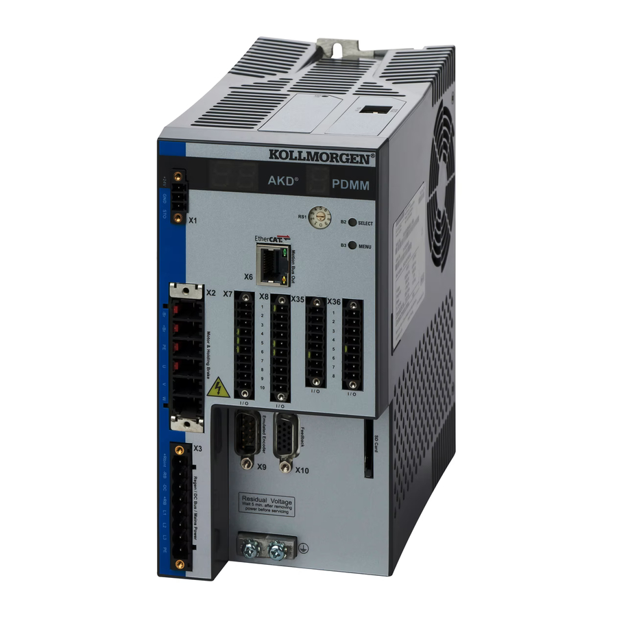
Das CC-Servoverstärkermodell ist mit Feldbussteckern sowohl für EtherCAT (X5 und X6) als auch für CANopen (X12 und X13) ausgestattet. Ein Software-Parameter (DRV.TYPE (s: 584)) erlaubt die Auswahl der vom Servoverstärker unterstützten Merkmale; Sie können EtherCAT und CANopen nicht gleichzeitig verwenden. KOLLMORGEN | Mai 2013... -
Seite 29: Grundlegendes Setup Des Servoverstärkers
AKD Benutzerhandbuch | 3 Grundlegendes Setup des Servoverstärkers 3 Grundlegendes Setup des Servoverstärkers 3.1 Grundlegendes Setup des Servoverstärkers 3.2 Anzeigecodes 3.3 AKD Setup Assistent KOLLMORGEN | Mai 2013... -
Seite 30: Grundlegendes Setup Des Servoverstärkers
Servoverstärker in internem dynamischem Bremsmodus (DRV.ACTIVE (s: 516) = Betriebs-FPGA begann Neustartprozedur, wartet auf residente Firmware zum StartOperational started reboot. Firmware-Download: fehlerhafte Betriebs-FPGA; Monitor-FPGA ist funktionsfähig. Firmware-Download: HW-Download (HW-Schalter wurde betätigt - Rev. 3 und höher). Firmware-Download: fehlerhafte Betriebs- FW. KOLLMORGEN | Mai 2013... -
Seite 31: Akd Setup Assistent
System die bevorzugten Einheiten auswählen, Ihre Betriebsart konfigurieren, das System feineinstellen (Tuning) und einfache Tippbewegungen innerhalb des Assistenten ausführen. Wenn die grundlegende Systemkonfiguration Ihren Anforderungen entspricht, können Sie Ihre Einstellungen im Servoverstärker speichern und den Assistenten beenden. KOLLMORGEN | Mai 2013... -
Seite 32: Anschluss Des Servoverstärkers
4.1 Die Stati „Verbindung“ und „Keine Verbindung“ 4.2 Keine Verbindung 4.3 Festlegen der IP-Adresse AKD-B, AKD-P, AKD-T 4.4 Kommunikation mit dem Servoverstärker bestätigen 4.5 Mit anderem Verstärker verbinden 4.6 TwinCAT and WorkBenchconfiguration 4.7 Behebung von Verbindungs- und Kommunikationsproblemen KOLLMORGEN | Mai 2013... -
Seite 33: Die Stati „Verbindung" Und „Keine Verbindung
4.3.1 IP-Adresse einstellen mit Drehschaltern Sie können die Drehschalter verwenden, um den Wert für die IP-Adresse zu wählen. Bei CANopen und einigen anderen Feldbussen legen die Drehschalter auch die Stationsadresse des Servoverstärkers für das jeweilige Netzwerk fest. KOLLMORGEN | Mai 2013... - Seite 34 Wenn der AKD direkt an einen PC angeschlossen wird, muss die statische IP Adressierung benutzt werden. Stellen Sie die Drehschalter S1 und S2 auf eine von 00 abweichende Stellung. Diese Einstellung generiert Adressen im Bereich von 192.168.0.1 bis 192.168.0.99. KOLLMORGEN | Mai 2013...
-
Seite 35: Ip-Adresse Mit Software Einstellen
Wenn IP.MODE auf 1 gesetzt ist (feste IP-Adressierung) startet der Servoverstärker mit einer IP- Adresse, die eventuell vom Host Computer nicht erreichbar ist. Wenn eine statische Adresse die Kommunikation verhindert, können die IP Einstellungen auf den Defaultzustand mit folgender Prozedur zurückgesetzt werden: KOLLMORGEN | Mai 2013... - Seite 36 Das Diplay blinkt 0.0.0.0 und dann versucht der Servoverstärker eine Adresse über DHCP zu beziehen. Schalten Sie die Spannung nicht ab, benutzen Sie nun WorkBench um die IP Adresse wie gewünscht einzustellen und speichern Sie die Werte im nicht-flüchtigen Speicher. KOLLMORGEN | Mai 2013...
-
Seite 37: Kommunikation Mit Dem Servoverstärker Bestätigen
Sie eine Verbindung herstellen. Blinken Wenn Sie auf Blinken klicken, blinkt die LED-Anzeige des gewählten Servoverstärkers 20 Sekunden MAC-Adresse Zeigt die MAC-Adresse des Servoverstärkers an. Die eindeutige MAC-Adresse ist auch auf dem Typenschild seitlich am Servoverstärker angegeben. KOLLMORGEN | Mai 2013... - Seite 38 (z. B. 1.2.3.4:1000). Discovery Wenn Sie ein Discovery Protokoll aus der Liste gewählt haben, können Sie den Protokoll Discovery Modus mit den folgenden vier Optionen konfigurieren: konfigurieren. 1. Ping 2. Broadcast 3. Broadcast und Ping 4. Kein Discovery KOLLMORGEN | Mai 2013...
-
Seite 39: Twincat And Workbenchconfiguration
Installation process for WorkBench is the same process as normal, except that it must be installed on the same machine as TwinCAT. Communication to the drive is done thru TwinCAT master and it's not possible to connect WorkBench to the master remotely. KOLLMORGEN | Mai 2013... -
Seite 40: Amsnetid Suchen Und Eingeben
4.7 Behebung von Verbindungs- und Kommunikationsproblemen 4.7.1 Gerät nicht angezeigt Wenn Ihr spezifischer Servoverstärker nicht in der Liste aufgeführt ist, konnte WorkBench den Verstärker nicht finden. Nachfolgend sind die häufigsten Gründe für das Nichterscheinen Ihres Servoverstärkers in der Liste aufgeführt: KOLLMORGEN | Mai 2013... -
Seite 41: Ip-Adresse Suchen Und Eingeben
B. 192.168.1.5. Sie können die IP-Adresse eingeben, wenn Sie Mehr drücken und das Feld Adresseangeben aktivieren. 4.7.3 TwinCAT Antrieb nicht angezeigt Wenn kein TwinCAT Gerät angezeigt wird, siehe AmsNetId suchen und eingeben. (s: 40) KOLLMORGEN | Mai 2013... -
Seite 42: Kommunikation Mit Dem Servoverstärker
AKD Benutzerhandbuch | 5 Kommunikation mit dem Servoverstärker 5 Kommunikation mit dem Servoverstärker 5.1 Übersicht 5.2 Identifizierung der IP-Adresse des Servoverstärkers 5.3 Kommunikationsbildschirm 5.4 Drehschalter 5.5 Verwendung der SD Karte KOLLMORGEN | Mai 2013... -
Seite 43: Übersicht
Fall weisen Sie dem Servoverstärker eine spezifische IP-Adresse zu und ändern die Netzwerkkonfiguration Ihres PC so, das dieser die statische Adresse erkennt. Die IP-Adresse lässt sich über die beiden Drehschalter an der Frontseite des Servoverstärkers einstellen. KOLLMORGEN | Mai 2013... - Seite 44 Setzt die Übertragungsrate auf Automatisch (Siehe Baudrate für CAN-Bus im CANopen Handbuch). Setzt die Übertragungsrate auf 125 (Siehe Baudrate für CAN-Bus im CANopen Handbuch). Setzt die Übertragungsrate auf 250 (Siehe Baudrate für CAN-Bus im CANopen Handbuch). Setzt die Übertragungsrate auf 500 (Siehe Baudrate für CAN-Bus im CANopen Handbuch). KOLLMORGEN | Mai 2013...
-
Seite 45: Statische Ip-Adressierung - Zuweisung Per Software
Sie die Werte im nicht-flüchtigen Speicher. 5.3 Kommunikationsbildschirm Wenn eine Verbindung vom Computer zum Servoverstärker besteht, zeigt der Kommunikationsbildschirm den erkannten Gerätetyp. 5.3.1 TCP/IP konfigurieren Durch Auswahl des IP Modus können die TCP/IP Eigenschaften konfiguriert werden. KOLLMORGEN | Mai 2013... -
Seite 46: Tcp/Ip Kommunikationsprotokolle
5.3.2 EtherNet/IP Bildschirm Der EtherNet/IP Bildschirm ist nur verfügbar, wenn ein EtherNet/IP Gerät angeschlossen ist. Sie können Positionseinheiten (EIP.POSUNIT (s: 593)) und Profileinheiten (EIP.PROFUNIT (s: 594)) einstellen. Sie können auch den Verbindungsstatus darstellen (EIP.CONNECTED (s: 592)). KOLLMORGEN | Mai 2013... -
Seite 47: Drehschalter
SD.LOAD (s: 905) und SD.SAVE (s: 906). 5.5 Verwendung der SD Karte 5.5.1 Übersicht Die SD Karte im AKD wird für Backup und Übertragung von Parametern und kompilierten Programmen verwendet. Dieses feature ist nur bei AKD's mit I/O Optionskarte verfügbar. KOLLMORGEN | Mai 2013... -
Seite 48: Speichern/Laden Mit Der Sd Karte
Wenn Sie den Computer nicht mit dem Servoverstärker verbinden wollen zum Beschreiben der SD Karte, können Sie auch handelsübliche SD Kartengeräte benutzen, um die Daten und Programme zu speichern. Beachten Sie, dass der Servoverstärker nur Dateien mit korrektem Dateinamen erkennen kann. Nennen Sie das Parameterfile drive.akd und das Programmfile program.bin. KOLLMORGEN | Mai 2013... -
Seite 49: Verwendung Von Workbench
AKD Benutzerhandbuch | 6 Verwendung von WorkBench 6 Verwendung von WorkBench 6.1 Begrüßungsbildschirm 6.2 Online 6.3 Offline 6.4 Übersicht 6.5 Beobachten 6.6 Einstellungen KOLLMORGEN | Mai 2013... -
Seite 50: Begrüßungsbildschirm
Wenn Ihr Servoverstärker nicht in der Liste erscheint, können Sie seine IP-Adresse (z. B. angeben 1.2.3.4) oder einen DNS-Namen eingeben. Optional können Sie auch eine alternative Port-Nummer anstelle des Standard-Ports (Port 23) angeben. Zum Beispiel würde 1.2.3.4:1000 den Port 1000 definieren. KOLLMORGEN | Mai 2013... -
Seite 51: Offline
Motor anzulegen. Dieser Befehl kann aus verschiedenen Gründen scheitern; siehe "DRV.EN " (➜ S. 545) für weitere Details. Deaktivierung Klicken Sie auf „Deaktivierung“, um die Leistungsstufe DRV.DIS (s: 531) und die am Motor angelegte Spannung auszuschalten. KOLLMORGEN | Mai 2013... -
Seite 52: Online Und Offline
Dieses Textfeld zeigt den Code für die im Servoverstärker DRV.VER (s: 586) ausgeführte Firmwareversion an. Download Klicken Sie auf Download, um die aktuellste AKD Firmware von KOLLMORGEN. Weitere Informationen über Firmware-Downloads finden Sie unter Firmware herunterladen (s: 296) Gesamtbetriebszeit Dieses Textfeld zeigt die Gesamtzeitdauer an, über die DRV.RUNTIME (s: der Verstärker bislang eingeschaltet war. -
Seite 53: Offline-Servoverstärker
Befehlsquelle anwendbar sind. Um alle verfügbaren Einstellungen für den AKD anzuzeigen (auch wenn diese nicht mit der aktuellen Betriebsart oder Befehlsquelle verwendet werden), rechtsklicken Sie auf Einstellungen und wählen Sie Alle Einstellungen anzeigen. 6.6.2 Ansicht „Einstellungen“ In der Hauptansicht für die Einstellungen können Sie Folgendes konfigurieren: KOLLMORGEN | Mai 2013... -
Seite 54: Zugehörige Themen
Bewegungs- und Ermöglicht dem Benutzer die Auswahl der Details zu den einzelnen Regelkreisgrafiken Regelkreisen über eine grafische Benutzeroberfläche. Zugehörige Themen Verwendung von Befehlsquellen und Betriebsarten (s: 136) für Details über die Konfiguration des Servoverstärkers für Ihre Anwendung. KOLLMORGEN | Mai 2013... -
Seite 55: Konfiguration Der Verstärkerleistung
AKD Benutzerhandbuch | 7 Konfiguration der Verstärkerleistung 7 Konfiguration der Verstärkerleistung 7.1 Leistung 7.2 Brems-Chopper KOLLMORGEN | Mai 2013... -
Seite 56: Leistung
Typs AKD-xxx07 (480 VAC) mit 240 VAC Eingangsspannung zu ermöglichen. Der Parameter VBUS.HALFVOLT hat Auswirkung auf die folgenden Spannungsgrenzwerte: Grenzwert für DC-Bus-Überspannung (siehe VBUS.OVFTHRESH (s: 943)). Spannungsgrenzwerte für die Aktivierung/Deaktivierung des Bremswiderstands. Spannungsgrenzwerte für die Aktivierung/Deaktivierung des Inrush-Relais. KOLLMORGEN | Mai 2013... -
Seite 57: Direkter Dc-Netzbetrieb
Spannungspegel des verwendeten Servoverstärkers. Nachfolgend sind die Spannungsbereiche aufgeführt: MODELL Pegel für Pegel für Unterspannung Überspannung AKD- 90 VDC 420 VDC zzzz06 AKD- 380 VDC 840 VDC zzzz07 Sie können die Busspannungswerte wie folgt im Bildschirm Leistung anzeigen: KOLLMORGEN | Mai 2013... - Seite 58 AKD Benutzerhandbuch | 7.1.1.2 Direkter DC-Netzbetrieb KOLLMORGEN | Mai 2013...
-
Seite 59: Brems-Chopper
Widerstand verwenden, wählen Sie <Benutzerdefiniert> und geben Sie die entsprechenden Werte für Ihren Bremswiderstand ein. Wenn Sie keinen Standard-Widerstand verwenden, wenden Sie sich an den technischen Kundendienst von KOLLMORGEN, um zu prüfen, dass dieser Widerstand für Ihr System geeignet ist. 7.2.3 Berechnung der Motorspitzenenergie und der Größe des Bremswiderstands Um festzustellen, ob Ihr System einen Bremswiderstand benötigt, müssen Sie die während der... - Seite 60 AKD Benutzerhandbuch | 7.2.3 Berechnung der Motorspitzenenergie und der Größe des Bremswiderstands Motorgeschwindigkeit, bei der die Verzögerung einsetzt Benötigte Verzögerungszeit Mit Hilfe einer Überschlagsrechnung können Sie Bemessungswerte des Bremswiderstands für Ihre spezifische Anwendung berechnen. Die Berechnungsgrundlagen finden Sie in unserem Produkt-WIKI auf der Seite http://www.wiki-kollmorgen.eu/wiki/tiki-index.php?page=Berechnung+der+Bremsleistung KOLLMORGEN | Mai 2013...
-
Seite 61: Auswahl Eines Kompatiblen Bremswiderstands
Resultate mit den Verstärkerkapazitäten und wählen Sie ggf. aus der Auflistung unten einen externen Bremswiderstand, der diesen Kapazitäten entspricht. Die unten gezeigten Widerstände sind im WorkBench Setup enthalten. Wenn für Ihre Anwendung kein passender Widerstand gelistet ist, wenden Sie sich an den KOLLMORGEN Kundendienst. Widerstandstyp AKD-... -
Seite 62: Konfiguration Der Parameter Für Den Widerstand
25,7 1500 Widerstand, 1500 W, 33 Ohm BAS-3000-33 DE-201407 Externer 77,0 3000 Widerstand, 3000 W, 33 Ohm BAR-600-23 DE-200613 Externer 27,5 Widerstand, 600 W, 23 Ohm BAR-1000-23 DE-200614 Externer 27,5 1000 Widerstand, 1000 W, 23 Ohm KOLLMORGEN | Mai 2013... -
Seite 63: Zugehörige Parameter
Widerstand, 2000 W, 15 Ohm BAS-3000-15 DE-103872 Externer 84,3 3000 Widerstand, 3000 W, 15 Ohm BAS-6000-15 DE-103873 Externer 91,7 6000 Widerstand, 6.000 W, 15 Ohm Zugehörige Parameter REGEN Parameters (s: 896) VBUS.OVWTHRESH (s: 944) VBUS.VALUE (s: 949) KOLLMORGEN | Mai 2013... -
Seite 64: Konfiguration Der Motoreinstellungen
AKD Benutzerhandbuch | 8 Konfiguration der Motoreinstellungen 8 Konfiguration der Motoreinstellungen 8.1 Motor 8.2 Rückführung 1 8.3 Rückführung 2 8.4 Rückführgeräte ohne Plug & Play 8.5 Foldback 8.6 Motor Haltebremse KOLLMORGEN | Mai 2013... -
Seite 65: Motor
8.1.2 Motor-Setup Wenn die automatische Motoreinstellung angewählt ist (MOTOR.AUTOSET = 1), konfiguriert der AKD die Motorparameter automatisch mit den im Feedback gespeicherten Daten (KOLLMORGEN Motoren mit SFD, EnDat, BiSS , Hiperface und Hiperface DSL). Bei automatischer Erkennung des Motors sind die Parameter auf der Bildschirmseite Motor ausgegraut und nicht zugänglich. -
Seite 66: Auswahl Eines Motors
3. Wird keine Übereinstimmung gefunden, erfolgt die Auswahl eines AKM-Motors. Für Motoren, die keine Plug & Play-Motoren sind, ist eine Datenbank mit Katalogmotoren auf Basis der verschiedenen Motorbaureihen von KOLLMORGEN verfügbar. Wenn Sie eine Motorbaureihe wählen, erscheint eine entsprechende Teilenummer. Sie können die Teilenummer nach Bedarf ändern. Je nach getroffener Auswahl wird der vollständige Motorname angezeigt. - Seite 67 Motorparameter zur Einrichtung der verschiedenen Rückführkreise und Grenzwerte, die mit dem gewählten Motor verknüpft sind. Wenn Sie einen benutzerspezifischen Motor aus der Liste wählen und auf OK klicken, wird der ausgewählte Spezialmotor auf der Bildschirmseite "Motorauswahl" angezeigt. KOLLMORGEN | Mai 2013...
-
Seite 68: Validierung Von Motorparametern
Parameter einer Überprüfung bedürfen. 8.1.6 Motor Derating Motor Derating (Leistungsbegrenzung) bei AKM oder VLM Motorserien. Wenn eine Motorhaltebremse oder ein anderes Feedback als Resolver gewählt wird, wird der Dauerstrom begrenzt. Resolver ohne Bremse (keine Begrenzung): SFD ohne Bremse (Begrenzung): KOLLMORGEN | Mai 2013... -
Seite 69: Motor Temperatur
Rückführung 1 In der Rückführungs-Ansicht können Sie das in Ihrem Motor montierte primäre Rückführungssystem konfigurieren. Wenn Sie Ihr Rückführsystem aus der Liste „Rückführungswahl“ wählen, werden unter dem Einstellrad die passenden Optionen für die Konfiguration der Rückführung angezeigt. KOLLMORGEN | Mai 2013... -
Seite 70: Übersicht
Plug-and-Play-Gerät verfügbar ist, wird der Modus Auto durch das erkannte Rückführsystem mit den entsprechenden Auflösungseinstellungen ersetzt. 8.2.2.2 Inkrementalgeber Der Inkrementalgeber ist kein Plug&Play Gerät. Inkrementalgeber sind mit einer Reihe von verschiedenen Strichzahlen verfügbar. Wenn Sie eine Inkrementalgeber Option wählen, müssen Sie die Auflösung in das KOLLMORGEN | Mai 2013... -
Seite 71: Sinus-Encoder
Feedback Polzahl. Zurzeit unterstützt der AKD nur die Standard-Resolver-Optionen von KOLLMORGEN. 8.2.2.8 SFD Smart Feedback Device (SFD) ist das Plug-and-Play-Gerät von KOLLMORGEN. SFD ermöglicht die schnelle und einfache Konfiguration im Modus Auto, der den Verstärker automatisch mit den Rückführungs- und Motorparametern konfiguriert. -
Seite 72: Verwendung Von Wake & Shake Mode 0 (Ws.mode 0)
Vor einer Freigabe des Servoverstärkers müssen die Motoreinflüsse kompensiert werden und die AKD Regelkreise stabil sein. Eine im Servoverstärker vorhandene Datenbank enthält die Kompensationswerte für zahlreiche Rotationsmotoren. Ein instabiles System funktioniert weder während noch nach dem WS-Prozess KOLLMORGEN | Mai 2013... -
Seite 73: Wake & Shake, Bildschirm Mehr
Initialisierung infolge von Drahtbruch, falschen Stromeinstellungen, sehr hoher Reibung usw. Durch Nullsetzen von WS.DISTMIN wird diese Funktion deaktiviert. Wake & Shake, Bildschirm Mehr Um weitere WS Einstellungen zu konfigurieren, klicken Sie auf Mehr unten im Fenster. Es erscheinen die folgenden Optionen: KOLLMORGEN | Mai 2013... -
Seite 74: Sonderfälle Für Ws
Bewegung erzielt wird, tritt ein Systemfehler auf. System mit hoher Lastträgheit oder Reibung Systeme mit starker Fehlanpassung der Last benötigen eventuell mehr Strom, als dem Vorgabewert für eine korrekte Kommutierung entspricht. Erhöhen bzw. verringern Sie ausgehend vom Vorgabewert KOLLMORGEN | Mai 2013... -
Seite 75: Verwendung Von Ws: Erweitert
Mit einem Wert für WS.NUMLOOPS von 20 erzielen Sie in vielen Anwendungen optimale Resultate. WS.T legt die Dauer fest, über die der Suchstrom angelegt wird. Bei einem stabilen Geschwindigkeitsregelkreis führt der Vorgabewert für WS.T in den meisten Anwendungen zu KOLLMORGEN | Mai 2013... -
Seite 76: Fehlersuche Und -Behebung Bei Ws
Zu hohe Reibung an der c. Motorlaufbahn auf Motorlaufbahn. Sauberkeit und mögliche Fremdkörper verhindern eine Reibung prüfen. Bewegung des Motors. d. WS.IMAX erhöhen. Sehr hohe Motorlast verhindert ausreichende Bewegung. WS.DISTMIN manuell zu hoch eingestellt. WS.IMAX zu niedrig. KOLLMORGEN | Mai 2013... -
Seite 77: Verwendung Von Wake & Shake Mode 1 (Ws.mode 1)
Motor mit Hall, die nicht phasengleich mit der Motorphase ausgerichtet sind. Wake & Shake konfigurieren Wake & Shake Mode 1 besitzt zwei konfigurierbare Parameter: WS.IMAX und WS.TSTANDSTILL. WS.IMAX (s: 996) kann im Wake & Shake Fenster konfiguriert werden. KOLLMORGEN | Mai 2013... -
Seite 78: Rückführung
Modus 1 – Der Eingang ist für Schritt- und Richtungssignale konfiguriert. Modus 2 – Der Eingang ist für Up/Down-Signale konfiguriert. Das Feld Auflösung dient der Festlegung der Auflösung des Geräts, das Sie als Ihre Signalquelle angegeben haben. Encoder-Emulationsausgang KOLLMORGEN | Mai 2013... -
Seite 79: Encoder-Emulation
Masters als Befehlseingang und befolgen diese Befehle (Geschwindigkeit und Richtung). Die Verstärker arbeiten mit einer internen Versorgungsspannung. Modus 1– A quad B mit Indeximpuls pro Umdrehung Ausgangsmodus 1 - A quad B mit Indeximpuls pro Umdrehung – Anschlussbild KOLLMORGEN | Mai 2013... -
Seite 80: Eingangsmodi 3, 4 Und 5 (Veraltet)
Indeximpulses erleichtern soll. Im Beispiel unten erfolgt der Impuls bei 20,5 positiven Umdrehungen des Motors. 8.3.1.5 Eingangsmodi 3, 4 und 5 (veraltet) Anschluss X9 kann auch für Eingangsmodi konfiguriert werden. Diese Eingangsmodi entsprechen den unten beschriebenen Signaltypen. Diese Bildschirmseite ermöglicht auch die Einstellung von Anschluss KOLLMORGEN | Mai 2013... -
Seite 81: Auflösung
Umdrehung. DRV.EMUEMTURN dient zur Einstellung des absoluten Indexpunktes im Modus 2 und DRV.HANDWHEEL zur Einstellung der Position, an der der Indeximpuls im Ausgangsmodus 2 ausgegeben wird. DRV.EMUEDIR (s: 538) DRV.EMUEMODE (s: 539) DRV.EMUEMTURN (s: 541) DRV.EMUERES (s: 543) DRV.EMUEZOFFSET (s: 544) KOLLMORGEN | Mai 2013... -
Seite 82: Rückführgeräte Ohne Plug & Play
Die Werte für Trägheit, Jm (Kg / cm2), und Drehmomentkonstante, Kt (Nm/A), stammen vom SFD oder von der Modellnummer des von Ihnen gewählten Motors. Konstanten Bandbreite des Geschwindigkeitsregelkreises – BW = der Vorgabewert lautet 75 Hz. Eingabe - Trägheitsverhältnis – Q = der Vorgabewert lautet 1. KOLLMORGEN | Mai 2013... -
Seite 83: Ausgabe - Regelkreis-Verstärkungen
Nenndauerstroms von Servoverstärker oder Motor nimmt die Fähigkeit zum Anlegen von Spitzenstrom ab. Die Grenzwerte für Motorstrom und Gesamtstrom werden aktiv verringert. Wenn das Fahrprofil über einen Zeitraum hinweg weniger Strom als den Dauernennstrom benötigt, beginnen die Werte für KOLLMORGEN | Mai 2013... -
Seite 84: Motorspitzenstrom-Zeit
8.5.4 Motorspitzenstrom-Zeit Der Spitzenstrom (MOTOR.IPEAK) wird gemeinsam mit der thermischen Spulenkonstante (MOTOR.CTFO) verwendet, um den maximalen Zeitraum zu ermitteln, über den der Motor Spitzenstrom handhaben kann. Der maximale Zeitraum (IL.MFOLDD) wird wie folgt im Foldback-Bildschirm angezeigt: KOLLMORGEN | Mai 2013... -
Seite 85: Motor-Foldback-Rampe
Erholungszeit für das Erreichen der maximalen Leistungsfähigkeit. 8.5.7 Gesamt-Foldback Der Gesamtgrenzwert ist der vorübergehende Mindestwert zwischen Servoverstärker- und Motor- Foldback. Das Gesamt-Foldback ist im Diagramm unten dargestellt. Sie können die Warn- und KOLLMORGEN | Mai 2013... -
Seite 86: Motor Haltebremse
Hat dieser Motor eine Bremse? MOTOR.BRAKE Verzögerung Bremse lösen Die Zeit zwischen der Aktivierung MOTOR.TBRAKERLS des Servoverstärkers und dem Lösen der Bremse. Verzögerung Bremse Die Zeit zwischen der Betätigung der MOTOR.TBRAKEAPP betätigen Bremse und der Deaktivierung des Servoverstärkers. KOLLMORGEN | Mai 2013... - Seite 87 Diese Seite wurde bewusst leer gelassen. KOLLMORGEN | Mai 2013...
-
Seite 88: Verwendung Der Positionserfassung
8.7.2 Konfiguration der Positionserfassung Wählen Sie zur Konfiguration der Positionserfassung die aus der Gruppe Einstellungen die Option Positionserfassung: Einstellung der Erfassungsquelle (CAP0.TRIGGER) Die Erfassungsquelle bestimmt, welcher Eingang am Servoverstärker die Positionserfassung auslöst. Optionen für die Erfassungsquelle: KOLLMORGEN | Mai 2013... -
Seite 89: Einstellen Des Erfassungsmodus (Cap0.Mode)
Vorbedingung = 1. ausgelöst und ist wahr, während die Erfassungsflanke auftritt. 3 – Triggerflanke während Die Erfassung wird nur während der Auswertung der Vorbedingung Vorbedingung = 0. ausgelöst und ist falsch , während die Erfassungsflanke auftritt. KOLLMORGEN | Mai 2013... -
Seite 90: Einstellen Einer Vorbedingung Für Komplexe Erfassung
Die Vorauswahl legt fest, welche Eingangsquelle die Vorbedingung auslöst (basierend auf den Einstellungen für Vorflanke und Vorfilter). Die Funktionsweise dieser Option ist mit derjenigen der oben beschriebenen Erfassungsquelle identisch. 8.7.3 KOLLMORGEN Testberichte Positionerfassung Testbericht basierend auf Leistungstest durch KOLLMORGEN: Capture Accuracy with External Sensor Drive: AKD-T00306-NBAN-000 Motor: AKM-21C... -
Seite 91: Verwendung Von Akd In Vertikalen Achsen
Verstärker die Bremse sofort an und versucht gleichzeitig, der normalen Disable Prozedure zu folgen. Der Wert ist begrenzt auf maximal 167 ms. Während dieser Zeit versucht der Verstärker, die Last auf Geschwindigkeit 0 zu verzögern. Wenn DRV.HWENDELAY = 0, ist die Funktion abgeschaltet (standard). KOLLMORGEN | Mai 2013... - Seite 92 Endstufe nicht sperren oder Stopp wenn .CS.TO andere Sperrkommandos möglich. Wenn Fehler CS geben, bis CS durchgeführt nicht möglich, wurde und die Bremse dynamische geschlossen ist. Bremsung. Fehler Dynamische – – Bremse Fehler Endstufe none MOTOR.BRAKEIMM = 1 gesperrt KOLLMORGEN | Mai 2013...
-
Seite 93: Konfiguration Mit Linearmotoren
„0 – Aus“ gesetzt werden, um die Option zu aktivieren. Auf der Bildschrimseite "Motor wählen", wählen Sie antweder die Motorfamilie IC und ICD Series Ironcore DDL oder IL Series Ironless DDL. Im Bildschirm „Motor wählen“ unter „Name“ die entsprechende Motorteilenummer wählen. KOLLMORGEN | Mai 2013... - Seite 94 Bildschirmseite "Feedback 1" in WorkBench. Wenn die Spulenbaugruppe in Richtung des Kabelausgangs bewegt wird (z. B. durch Ziehen am Spulenkabel), müsste der Wert der Positionsrückführung positiv steigen, und der graue Block in der Motorgrafik müsste sich nach rechts bewegen. Bei entgegengesetzter KOLLMORGEN | Mai 2013...
- Seite 95 AKD Benutzerhandbuch | 10.1 Anschluss eines DDL-Motors an einen AKD Servoverstärker Richtung müssen die Signale A+ und A- an der Linearskala vertauscht werden, um die Phasendrehrichtung zu korrigieren. Der Motor ist jetzt für die Kompensation von Geschwindigkeits- und Positionsregelkreis bereit. KOLLMORGEN | Mai 2013...
-
Seite 96: Auswählen Von Einheiten Für Ihre Anwendung
AKD Benutzerhandbuch | 11 Auswählen von Einheiten für Ihre Anwendung 11 Auswählen von Einheiten für Ihre Anwendung 11.1 Auswählen und Speichern von Einheiten 11.2 Beispiel KOLLMORGEN | Mai 2013... -
Seite 97: Auswählen Und Speichern Von Einheiten
4 – Schritte (16 Bit) (65.536 /U) Benutzerspezifische Einheiten Der Servoverstärker verwendet unabhängig von den Einstellungen für die Einheiten eine volle 32-Bit- Quantisierung für interne Berechnungen. Benutzerspezifische Einstellungen für die Einheiten haben keine Auswirkungen auf die Leistung, Auflösung oder Genauigkeit des Servosystems. KOLLMORGEN | Mai 2013... - Seite 98 Sie können UNIT.PIN und UNIT.POUT direkt unter Nur Motor im Feld Typ der Mechanik wählen eingeben. In diesem Beispiel wird die Skalierung wie folgt angepasst: UNIT.PIN wird wie folgt berechnet: 10 mm/Spindeldrehung * 1 Spindeldrehung/5 Motordrehungen = 2 mm/Motordrehung KOLLMORGEN | Mai 2013...
- Seite 99 AKD Benutzerhandbuch | 11.2 Beispiel Zugehörige Parameter UNIT Parameters (s: 931) DRV.NVSAVE (s: 572) MOTOR.TYPE (s: 800) KOLLMORGEN | Mai 2013...
-
Seite 100: Konfiguration Der Allgemeinen Servoverstärker-Einstellungen
12.1 Digitale Eingänge und Ausgänge 12.2 Befehls-Buffer 12.3 Analogeingang 12.4 Analogausgang 12.5 Elektronisches Getriebe 12.6 Grenzwerte 12.7 Programmierbarer Endschalter 12.8 Freigabe/Deaktivierung 12.9 Kontrollierter Stopp 12.10 Dynamisches Bremsen 12.11 Not-Halt 12.12 Safe Torque Off (STO) 12.13 Verhalten bei Unterspannungsfehler KOLLMORGEN | Mai 2013... -
Seite 101: Digitale Eingänge Und Ausgänge
Änderungen an diesem Eingang ignoriert. Beispiel: -->DIN1.MODE 2 - Setzt den Eingangsmodus auf Fahrauftrag starten. -->DIN1.PARAM 1 - Legt fest, dass der zu startende Fahrauftrag 1 ist. -->MT.LIST - Stellt sicher, dass der Fahrauftrag 1 existiert. KOLLMORGEN | Mai 2013... - Seite 102 Modus 9: Befehlspuffer Dieser Modus dient zur Ausführung vier verschiedener Befehlspuffer-Sätze. Jeder Satz enthält zwei Puffer: Low und High, für insgesamt acht Puffer. DINx.PARAM für diesen Modus kann 1 bis 4 lauten und bestimmt, welcher Puffersatz verwendet wird. KOLLMORGEN | Mai 2013...
- Seite 103 Variable wird durch DINx.PARAM festgelegt. Der Parameter wird in Positionseinheiten angegeben und wird verwendet, um eine Phasenverschiebung während des Betriebs im elektronischen Getriebemodus hinzuzufügen. Dieser Modus ist für Betriebsart 2 (Position) und Befehlsquelle 2 (elektronisches Getriebe) gültig. Beispiel KOLLMORGEN | Mai 2013...
- Seite 104 Screenshot unten zeigt die aktuelle, für den Servoverstärker eingestellte Befehlsquelle/Betriebsart an. Der Servoverstärker befindet sich in diesem Modus, wenn der Digitaleingang nicht auf High gesetzt ist. Dieser Low-Status wird durch die ursprünglichen Einstellungen für DRV.CMDSOURCE und DRV.OPMODE bestimmt. KOLLMORGEN | Mai 2013...
- Seite 105 Eingang kombinierte Kombination aus Sollwertquelle/Betriebsart aktiv. Wenn zusätzliche Eingänge aktiv werden, dann ist die für den Eingang mit der niedrigsten Nummer konfigurierte Kombination aus Befehlsquelle/Betriebsart aktiv. Beispiel Setzen Sie voraus: Eingang 1 ist für elektronisches Getriebe/Position konfiguriert. Eingang 2 ist für Service/Geschwindigkeit konfiguriert. KOLLMORGEN | Mai 2013...
- Seite 106 Multiplikation der Analogspannung mit -1 und zusätzliches Auslösen eines Software-Enable. 0x06 Nullsetzen der gemessenen Analogspannung und zusätzliches Auslösen eines Software-Disable. 0x07 Multiplikation der Analogspannung mit 1 und zusätzliches Auslösen eines Software-Disable. 0x08 Multiplikation der Analogspannung mit -1 und zusätzliches Auslösen eines Software-Disable. KOLLMORGEN | Mai 2013...
-
Seite 107: Digitalausgänge
Software-Grenze erreicht wird. Software-Grenzen werden in der Ansicht Grenzwerte eingestellt. Im Fenster Grenzwerte ist Position 0 der Positionsgrenzwert für negativen Verfahrweg und Position 1 der Positionsgrenzwert für positiven Verfahrweg. Dieser Modus ist gültig für alle Kombinationen aus Betriebsart und Sollwertquelle. KOLLMORGEN | Mai 2013... - Seite 108 PLS.STATE Bits auf High gesetzt ist (PLS ist aktiv) und das entsprechende Bit im Parameter DOUTx.PARAM ebenfalls auf High gesetzt wurde. Der Befehl DOUTx.PARAM verbindet die PLS.STATE Bits mit dem Digitalausgang selbst und fungiert somit als Freigabemaske. Dieser Modus ist gültig für alle Kombinationen aus Betriebsart und Sollwertquelle. Beispiel KOLLMORGEN | Mai 2013...
- Seite 109 Motion Task Auswahl 2-Position 0-Service Start Referenzfahrt starten 2-Position 0-Service Tippbetrieb starten 2-Position 0-Service Zero Latch alle alle Befehlspuffer alle alle Steuerung des alle alle Fehlerrelais Referenzfahrt-Schalter 2-Position 0-Service Kontrollierter Stopp alle alle Schnellhalt alle 0-Service KOLLMORGEN | Mai 2013...
-
Seite 110: Digitale Eingänge (X7/X8)
Wenn ein Eingang programmiert wurde, muss dies im Verstärker gespeichert werden. Je nach der ausgewählten Funktion sind die Eingänge HIGH oder LOW aktiv. Die Eingänge können mit geschalteten +24 V ("Source") oder geschaltetem GND ("Sink") verwendet werden. Siehe folgende Diagramme. Anschlussbild (Anschluss Typ "Source", Beispiel) KOLLMORGEN | Mai 2013... - Seite 111 AKD Benutzerhandbuch | 12.1.5 Digitale Eingänge (X7/X8) KOLLMORGEN | Mai 2013...
- Seite 112 AKD Benutzerhandbuch | 12.1.5 Digitale Eingänge (X7/X8) Anschlussbild (Anschluss Typ "Sink", Beispiel) KOLLMORGEN | Mai 2013...
-
Seite 113: Digitale Eingänge 1 Und
X8/4, aktiv high). Die Freigabe ist nur möglich, wenn am STO Eingang ein 24 V-Signal anliegt . Im deaktivierten Status (Low Signal) erzeugt der angeschlossene Motor kein Drehmoment. Eine Software-Freigabe durch die Setup-Software ist ebenfalls erforderlich (UND-Verknüpfung). Die Software Freigabe in WorkBench kann auf permanent gesetzt werden. KOLLMORGEN | Mai 2013... -
Seite 114: Befehls-Buffer
Parameter unter Verwendung eines Digitaleingangs ändern. Der Servoverstärker verfügt über vier Befehlspuffer. Ein für den Befehlpuffer-Modus konfigurierter Digitaleingang ist mit einem Befehlspuffersatz verknüpft. Dies wird durch den Benutzer festgelegt (siehe Pfeil 1). In diesem Fall wird Befehlspuffer 1 verwendet. KOLLMORGEN | Mai 2013... -
Seite 115: Bearbeitung Der Befehlspuffer
Maus über das Feld Param fahren, zeigt der Tooltipp den aktuellen Inhalt des „Low“- und des „High“- Befehlspuffers im Servoverstärker an. Klicken Sie zum Bearbeiten des gewählten Befehlsspeichers auf Bearbeiten. Daraufhin erscheint der Bildschirm des Befehlspuffer-Editors. KOLLMORGEN | Mai 2013... - Seite 116 Meldung: „Die Befehle wurden geändert und nicht im Servoverstärker gespeichert. Möchten Sie ohne Speicherung der Änderungen schließen?“. Befehle und Parameter werden in separate Zeilen eingegeben.Zwischen Parameter und Wert wird ein Leerzeichen gesetzt. KOLLMORGEN | Mai 2013...
-
Seite 117: Verhalten Des Befehlspuffers
Bei Betriebsart „Geschwindigkeit“ ist dieser Wert die 396) Geschwindigkeit pro 1 Volt am Analogeingang. Hinweis: Die Skalierung in KAS beträgt 80% der Skalierung im AKD. Im AKD 10 V = 32767 jedoch in KAS 10 V = 26126 KOLLMORGEN | Mai 2013... -
Seite 118: Zugehörige Parameter
Analogausgang (s: 421) Tiefpass-Filter Aktiviert einen Software-basierten Tiefpass-Fillter des analogen AOUT.CUTOFF Ausgangswert. 0 Hz deaktiviert diese Funktion. (s: 417) Die analogen Ausgangsmodi umfassen: AOUT.MODE Beschreibung Benutzervariable. Das analoge Ausgangssignal wird vom Benutzer festgelegt (mithilfe von AOUT.VALUEU). KOLLMORGEN | Mai 2013... -
Seite 119: Elektronisches Getriebe
Zur Steuerung eines AKD mit elektronischem Getriebe muss die Sollwertquelle (DRV.CMDSOURCE) auf 2-Elektronisches Getriebe und die Betriebsart (DRV.OPMODE) auf 2-Position Mode gesetzt sein. Die Eingangsmodi von Stecker X9 dienen zur Konfiguration des AKD für die Nutzung des elektronischen Getriebes. KOLLMORGEN | Mai 2013... -
Seite 120: Grenzen
Bei der Geschwindigkeitsabstimmung beschleunigt der Motor auf dieselbe Geschwindigkeit, ungeachtet jeglicher Schrittverluste während der Beschleunigungsperiode. Bei der Positionsabstimmung stimmt der Motor den Positionsbefehl vom Übergangspunkt ab, indem er beschleunigt, um die während der Beschleunigungsphase verlorenen Schritte aufzuholen. KOLLMORGEN | Mai 2013... -
Seite 121: Ermittlung Der Maximalen Kabellänge
Maximal zulässige Kabellänge für die Beispielanwendung = 26,9 m = (Maximaler Kabelwiderstand) 5 Ohm ÷ 0,186 Ohm/m Zugehörige Parameter GEAR Parameters (s: 664) DRV.CMDSOURCE (s: 522) DRV.EMUEMODE (s: 539) DRV.EMUERES (s: 543) DRV.HANDWHEEL (s: 550) DRV.OPMODE (s: 574) KOLLMORGEN | Mai 2013... -
Seite 122: Grenzwerte
Bemessungsdaten des Motors festlegen, falls die Anwendung einen gewissen Leistungsüberhang erfordert. Bedenken Sie jedoch, dass der Motor mechanischen Beschränkungen unterworfen ist, deren Überschreitung zu Schäden führen kann. Es wird empfohlen, die Werte entsprechend den Bemessungsdaten des gewählten Motors zu belassen. KOLLMORGEN | Mai 2013... -
Seite 123: Programmierbarer Endschalter
3. Der digitale Ausgangsmodus ist jetzt für PLS eingestellt.Klicken Sie auf den Link Gehe zu programmierbarem Endschalter (siehe 2 unten), um den PLS-Bildschirm zu öffnen (dieser Bildschirm ist auch in der Baumansicht von WorkBench aufgeführt). Der PLS-Bildschirm dient zur Festlegung der Einschaltpositionen für den bzw. die Ausgänge. KOLLMORGEN | Mai 2013... - Seite 124 Der abschließende Schritt beinhaltet die Konfiguration des OR-Gates für die Schalter, an denen ein Ausgang ausgelöst wird. Das Gate ist im Bildschirm konfigurierbar, wenn ein digitaler Ausgang auf Modus 15 – Progr.Endschalter-Status gesetzt ist. Da nur PLS1 konfiguriert ist, wählen Sie PLS 1 (siehe Pfeil oben). KOLLMORGEN | Mai 2013...
-
Seite 125: Single Shot-Modus
Der Single Shot-Modus (Einzelschussmodus) ist ein spezieller PLS-Modus. Der Single Shot-Modus (siehe 1 unten) schaltet den Ausgang ein, bis er zurückgesetzt wird (siehe 2 unten). Der Normalbetrieb dieses Modus ist in der Regel davon abhängig, dass eine Maschinensteuerung den PLS mit dem Feldusobjekt für PLS.RESET zurücksetzt. KOLLMORGEN | Mai 2013... -
Seite 126: Freigabe/Deaktivierung
Drehmomentabschaltung (Safe Torque Off, STO) und deckt auf diese Weise verschiedenste Bedingungen ab. Hardware-Freigabemodus: Der AKD bietet zwei Methoden zur Hardware Freigabe. Die Auswahl der Methode erfolgt über DRV.HWENMODE. Modus 0 ermöglicht die Freigabe des Servoverstärkers und das Löschen von KOLLMORGEN | Mai 2013... -
Seite 127: Vorgabe Für Software-Freigabe
Deaktivierungsmodus folgt, bevor er deaktiviert wird. Dies erfolgt unabhängig von der gewählten Methode und etwaigen Warnungen wegen eines Emergency-Timeout-Fehlers. Die Ausführung sämtlicher Deaktivierungsmodi ist von der Art des empfangenen Deaktivierungsbefehls abhängig. Kritische Fehler, eine Hardware-Deaktivierung oder STO führen zum unverzüglichen KOLLMORGEN | Mai 2013... -
Seite 128: Servoverstärker-Status
Die Mehr-Schaltfläche dient zur Anzeige des Statusdiagramms für die Konfiguration des kontrollierten Stopps. Sie zeigt außerdem das Blockschaltbild für den kontrollierten Stopp an. Es sind zwei Blockschaltbilder verfügbar: eines mit montierter Bremse und eines ohne Bremse. KOLLMORGEN | Mai 2013... -
Seite 129: Kontrollierter Stopp
Ein Fehler führt zu einem kontrollierten Stopp durch den Servoverstärker. Siehe Fehler und Warnmeldungen (s: 264) für eine Auflistung der Fehler, die einen kontrollierten Stopp einleiten. Der Mechanismus für kontrollierten Stopp wird in folgenden Fällen aktiviert: KOLLMORGEN | Mai 2013... - Seite 130 Servoverstärker möglicherweise niemals das Ende des kontrollierten Stoppprozesses. In diesem Fall kann der Servoverstärker nach Ablauf von DRV.DISTO deaktiviert werden, selbst dann, wenn der kontrollierte Stopp nicht abgeschlossen ist. Diagramm für kontrollierten Stopp KOLLMORGEN | Mai 2013...
-
Seite 131: Zugehörige Parameter Und Befehle
Stopp. 1 = Es erfolgt ein kontrollierter Stopp). DIN1.MODE TO DIN24.MODE (s: 484) DRV.DIS (s: 531) DRV.DISTO (s: 536) DRV.DISMODE (s: 532) Zugehörige Themen: Not-Halt (s: 132) Digitale Eingänge und Ausgänge (s: 101) Fehler und Warnmeldungen (s: 264) KOLLMORGEN | Mai 2013... -
Seite 132: Dynamisches Bremsen
Widerstands für den Fall, dass eine höhere Leistung benötigt wird. Zugehörige Themen Ausführliche Informationen zu diesem Thema finden Sie in Abschnitt 6.14 Dynamische Bremsung in der AKDBetriebsanleitung. DRV.DISMODE (s: 532) DRV.DBILIMIT (s: 525) 12.11 Not-Halt KOLLMORGEN | Mai 2013... -
Seite 133: Stopp/Not-Halt/ Not-Aus
Stopp der Kategorie 0 Priorität besitzen muss. Bei Bedarf sind Vorkehrungen für den Anschluss von Schutzvorrichtungen und Verriegelungen zu treffen. Falls notwendig, muss die Stopp-Funktion ihren Status an die Steuerlogik melden. Ein Zurücksetzen der Stopp-Funktion darf nicht zu einer Gefahrensituation führen. KOLLMORGEN | Mai 2013... -
Seite 134: Not-Halt
Not-Aus wird erreicht durch Abschalten der Energieeinspeisung mit elektromechanischen Schaltgeräten. Das führt zu einem Stopp der Kategorie 0. Wenn diese Stopp Kategorie für die Maschine nicht zulässig ist, muss der Not-Aus durch andere Maßnahmen (z.B. Schutz gegen direktes Berühren) ersetzt werden. KOLLMORGEN | Mai 2013... -
Seite 135: Safe Torque Off (Sto)
Wenn ein Unterspannungsfehler auftritt, wird der Servoverstärker deaktiviert und es werden folgende Warnungen ausgegeben: WorkBench Warnung: 502 Unterspannung Bus Warnung der LEDs am Servoverstärker: Linke LED zeigt [F] an, rechte LED zeigt [u-V] an. Der Fehlerrelaisausgang wird eingeschaltet. KOLLMORGEN | Mai 2013... -
Seite 136: Verwendung Von Befehlsquellen Und Betriebsarten
AKD Benutzerhandbuch | 13 Verwendung von Befehlsquellen und Betriebsarten 13 Verwendung von Befehlsquellen und Betriebsarten 13.1 Übersicht 13.2 Verwendung von Befehlsquellen und Betriebsarten 13.3 Stromregelkreis 13.4 Geschwindigkeitsregelkreis 13.5 Positionsregelkreis KOLLMORGEN | Mai 2013... -
Seite 137: Übersicht
Ausgabe eines externen Encoders im Anschluss an eine Bewegung unter Verwendung einer elektronischen Getriebeübersetzung zu überwachen. Bei Verwendung der Befehlsquelle „Elektronisches Getriebe“ muss als Betriebsart der Positionsregelkreis gewählt werden. Diese Betriebsart wird auch für Schritt- und Richtungseingänge verwendet. KOLLMORGEN | Mai 2013... -
Seite 138: Analog
Die Feineinstellung des Stromregelkreises erfolgt auf Basis der Induktivität des mit dem Servoverstärker verwendeten Motors. Die Stromregelkreis-Verstärkung wird automatisch so eingestellt, dass die idealisierte Übergangsfrequenz des Stromregelkreises IL.KP/L in rad/s lautet, wobei L für die Leitungsinduktivität des Motors steht. KOLLMORGEN | Mai 2013... -
Seite 139: Anpassung Des Stromregelkreises
Parameters für Stromregelkreis-Proportionalverstärkung erforderlich. Wenn manuelle Einstellungen des Parameters für die Stromregelkreis-Proportionalverstärkung vorgenommen werden, führt eine Wiederholung des Motor-Setups dazu, dass die Änderungen überschrieben werden und der von KOLLMORGEN berechnete Wert wieder hergestellt wird. Zugehörige Parameter IL Parameters (s: 710) DRV.OPMODE (s: 574) -
Seite 140: Verwendung Des Bildschirms „Kp-Anpassung" In Workbench
Skalierungswert ein: 0 - 100 % des Stromwerts. Beispiel Wenn der in IL.KP eingegebene Wert für die Stromregelkreis-Verstärkung 40,124 lautete (siehe oben) und eine Verstärkung von 36 gewünscht war, geben Sie einen Skalierungswert von 90 % für die gewünschten Strombereiche ein. KOLLMORGEN | Mai 2013... -
Seite 141: Verwendung Des Terminal-Bildschirms Für Die Kp-Anpassung
Beschleunigung für Fahraufträge oder Getriebe. Diese Beschleunigungs- und Verzögerungsgrenzwerte werden auch in der Ansicht „Service-Fahrt“ und in der Ansicht „Grenzwerte“ (DRV.ACC (s: 514) and DRV.DEC (s: 526)) angezeigt. Geschwindigkeits-Festsetzung. Die Geschwindigkeits-Festsetzung hat Auswirkungen auf die Höchstgeschwindigkeit des Servoverstärkers, wenn die Befehlsquelle Service KOLLMORGEN | Mai 2013... - Seite 142 5–Autotuned BiQuad Wenn das PST nach Abschluss des Autotuning-Prozesses einen Filter setzt, werden die Werte in den BiQuad-Filter eingegeben und als schreibgeschützte Werte angezeigt. Status: Status: Die Status-Registerkarte zeigt Parameter an, die für die Leistung des Geschwindigkeitsregelkreises relevant sind. KOLLMORGEN | Mai 2013...
-
Seite 143: Standardeinstellungen Und Änderungen Des Geschwindigkeitsregelkreises
Zähler Q = Sqrt(2)/2 (= 0.707) Nenner Frequenz = F Nenner Q = Sqrt(2)/2 (= 0.707) BiQuad als LeadLag bei Frequenz F, Verstärkung G Zähler Frequenz = F * 10^(-G/80) Zähler Q = Sqrt(2)/2 (= 0.707) KOLLMORGEN | Mai 2013... -
Seite 144: Positionsregelkreis
Status: Diese Registerkarte zeigt die aktuellen Werte für Sollposition (PL.CMD (s: 838)), Positionsrückführung (PL.FB (s: 846) ), Positionsfehler (PL.ERR (s: 839)) und Geschwindigkeitsbefehl (VL.CMD (s: 961)) an. 13.5.3 Standardverhalten und Änderungen des Positionsregelkreises Standardmäßig wird nur eine Proportionalverstärkung (PL.KP (s: 854)) im Positionsregelkreis angewandt. KOLLMORGEN | Mai 2013... -
Seite 145: Änderungen Des Positionsregelkreises Basierend Auf Schiebereinstellung
Bereichs zurück. Dieses Verhalten hat Auswirkungen auf einige Servoverstärker-Funktionen, die bei aktivierter Modulo-Funktion mit moduloskalierten Positionsvariablen arbeiten. Die Abbildung unten veranschaulicht den Verlauf des Ist-Positionswerts (PL.FB) für lineare Skalierung und Modulo-Skalierung, wenn sich der Motor kontinuierlich in eine positive Richtung bewegt: KOLLMORGEN | Mai 2013... -
Seite 146: Konfiguration Der Modulo-Achse In Workbench
Die folgenden Parameter werden in das Modulo-Format umgewandelt, wenn ihre Werte von einem Anwender, einem Feldbus oder dem Software-Oszilloskop abgerufen werden. PL.FB (s: 846): Die Ist-Position des Servoverstärkers wird gemäß Modulo-Skalierung konvertiert. PL.CMD (s: 838): Die Sollposition des Servoverstärkers wird gemäß Modulo-Skalierung konvertiert. KOLLMORGEN | Mai 2013... -
Seite 147: Von Der Modulo-Achse Betroffene Servoverstärker-Funktionen
Die nachstehende Abbildung zeigt das Verhalten des Servoverstärkers für den Fall, dass der Modulo- Bereich als Ganzzahl in den Multiturn-Rückführbereich passt. Nehmen wir zur Vereinfachung an, dass ein Multiturn-Rückführbereich 4 Rückführ-Umdrehungen umfasst und dass der gewählte Modulo-Bereich auf 2 Rückführ-Umdrehungen eingestellt ist. KOLLMORGEN | Mai 2013... - Seite 148 Multiturn-Rückführbereich 4 Rückführ-Umdrehungen umfasst und dass der gewählte Modulo-Bereich auf 2,5 Rückführ-Umdrehungen eingestellt ist. Wie in der Abbildung oben gezeigt, wird der gewählte Modulo-Bereich nicht an exakt derselben Stelle wiederholt, an der die angeschlossene Rückführeinheit überläuft. Die Bewegung kann sich über mehrere KOLLMORGEN | Mai 2013...
- Seite 149 Bereiche der Multiturn-Rückführeinheit erstrecken, aber der Servoverstärker kann nach einem Aus- und Wiedereinschalten der Stromversorgung die Modulo-Position nicht korrekt neu berechnen. Beispiel Die Modulo-konvertierte Position, die 5 Umdrehungen der Rückführeinheit darstellt, entspricht nicht der Modulo-Position, die 1 Umdrehung der Rückführeinheit darstellt. KOLLMORGEN | Mai 2013...
-
Seite 150: Bewegung Erzeugen
AKD Benutzerhandbuch | 14 Bewegung erzeugen 14 Bewegung erzeugen 14.1 Referenzfahrt 14.2 Fahraufträge 14.3 Service Fahrt 14.4 Bewegungsprofiltabelle 14.5 Tippbetrieb 14.6 Status des Antriebs KOLLMORGEN | Mai 2013... -
Seite 151: Referenzfahrt
Endschaltern die Hinweise im Abschnitt „Eingang/Ausgang“ zur ordnungsgemäßen Verdrahtung. Standardfenster „Home“ Im Fenster „Home“ können Sie die Referenzfahrtmethode auswählen und die Referenzfahrteinstellungen konfigurieren. Dieses Fenster beinhaltet auch übersichtliche Bedienelemente zum Starten und Bestätigen des erfolgreichen Abschlusses der Referenzfahrt. KOLLMORGEN | Mai 2013... -
Seite 152: Moduswahl
Feld an, wie die digitalen Eingänge konfiguriert sind und ein Link zur Bildschirmseite Digitale Eingänge wird angeboten. Bei einer Referenzfahrt zu einem sofortigen Stopp können Sie im Feld „Spitzenstrom“ den während der Referenzfahrt gewünschten Grenzwert für den Spitzenstrom festlegen. KOLLMORGEN | Mai 2013... -
Seite 153: Bedienelemente
Methode verwenden, wenn ein positiver oder negativer Endschalter verfügbar ist, den Sie als Referenzpunkt festlegen möchten. Endschalter sollten als Active Low definiert sein (kabelbruchsicher, Verstärker stoppt die Fahrt im Fehlerfall). Dieser Homing Mode beinhaltet folgende Sequenz: KOLLMORGEN | Mai 2013... -
Seite 154: Homing Mode 2: Referenzieren Auf Endschalter Mit Nullpunkt
4. Der Motor fährt in die Referenzposition (HOME.P). Außerdem wird der Distanz-Offset der Bewegung (sofern vorhanden) angewandt, der sich im mechanischen Nullwinkel der Rückführeinheit befindet. Die Werte für Distanz und Position können wie für Homing Mode 0 beschrieben verwendet werden. KOLLMORGEN | Mai 2013... -
Seite 155: Homing Mode 3: Referenzieren Auf Endschalter Mit Index
Vorgangs nach dem Indexsignal. Die Referenzposition ist gefunden, sobald der Servoverstärker das Indexsignal erkannt hat. 4. Die Ist- und die Sollposition des Servoverstärkers werden auf den Wert für HOME.P eingestellt, sobald der Index-Impuls erkannt wird. Der Servoverstärker bremst dann auf KOLLMORGEN | Mai 2013... -
Seite 156: Homing Mode 4: Referenzieren Auf Endschalter
Lokalisierung der Referenzposition aktiviert. Die Ist- und die Sollposition des Servoverstärkers werden unverzüglich auf den Positionswert (HOME.P) eingestellt, und der Motor bremst auf Null-Drehzahl ab. Die Achse wird dann auf die Position (HOME.P) + Distanz-Offset (HOME.DIST) verschoben. Beispiel für Homing Mode 4 KOLLMORGEN | Mai 2013... -
Seite 157: Homing Mode 5: Referenzieren Auf Referenzschalter Mit Nullpunkt
Referenzschalter erreicht hat. Sobald dieser Schalter ausgelöst wird, bewegt sich der Motor zur Position des Nullwinkels plus zusätzliche 60 Grad, wie gewünscht. Homing Mode 6: Referenzieren auf Referenzschalter mit Index Ähnlich wie die Suche nach dem Referenzeingang, folgt diese Methode derselben Logik wie die anderen KOLLMORGEN | Mai 2013... - Seite 158 Die Ist- und die Sollposition des Servoverstärkers werden unverzüglich auf den Wert für HOME.P eingestellt, sobald das Indexsignal erkannt wird. Der Motor bremst auf Nulldrehzahl ab. Die Achse wird dann auf die Position (HOME.P) + Distanz-Offset (HOME.DIST) verschoben. KOLLMORGEN | Mai 2013...
-
Seite 159: Homing Mode 7: Referenzieren Auf Nullpunkt
Homing Mode 9: Referenzieren auf mechanischen Anschlag mit Nullpunkt Dieser Homing Mode beinhaltet folgende Sequenz: 1. Bei Einleitung dieses Homing Mode bewegt sich der Motor gemäß dem Richtungswert (HOME.DIR), bis der Positionsfehler den Wert für Nacheilung (HOME.PERRTHRESH) überschreitet. KOLLMORGEN | Mai 2013... -
Seite 160: Homing Mode 10: Referenzieren Auf Mechanischen Anschlag Mit Index
Rückführungstyps 10, 11, 20, 21). Voraussetzung für diese Methode ist, dass der Erfassung-Modus im Home-Bildschirm eingeschaltet ist. Wenn Mode 10 ausgewählt ist, wird die Schaltfläche Erfassung einstellen angezeigt (siehe nachstehenden Pfeil). Klicken Sie auf Erfassung einstellen, um die Positionserfassung richtig für eine ordnungsgemäße Referenzfahrt mit einem Index-Impuls einzustellen. KOLLMORGEN | Mai 2013... -
Seite 161: Homing Mode 11: Referenzierung Auf Indexsignal
Nach Auslösung der Referenzfahrt wird folgende Routine durchgeführt: 1. Der Motor beginnt eine Bewegung in der mit HOME.DIR eingestellten Richtung. 2. Der Motor sucht während dieses Vorgangs nach dem Index-Impuls. 3. Wenn der Motor den Index-Impuls findet, ist die Referenzposition ebenfalls gefunden. KOLLMORGEN | Mai 2013... -
Seite 162: Homing Mode 12: Referenzierung Auf Referenzschalter Mit Mechanischem Anschlag
Wenn der Referenzschalter nicht aktiv ist, bremst der Motor zum Stillstand ab und startet mit der Referenzfahrt Sequenz. Homing Mode 13: Absolut-Modus - Rückführungsposition verwenden Dieser Modus ist bei Verwendung einer Multiturn-Rückführungseinheit mit dem AKD zu verwenden. Da KOLLMORGEN | Mai 2013... -
Seite 163: Fahraufträge
Aufträge hinzufügen und löschen. Die auf diese Weise erstellte Datentabelle bleibt in WorkBench, bis Sie die Aufträge in den Servoverstärker laden. Wenn der Fahrauftrag geladen ist, haben Sie Zugriff auf die grafische Darstellung der Fahrten (wie in vorherigen Versionen von WorkBench). KOLLMORGEN | Mai 2013... -
Seite 164: Verwendung Von Fahraufträgen
Fahraufträge hinzufügen, werden die neuen Aufträge als Verzweigungen angezeigt. In der Ausgangsansicht für Fahraufträge können Sie alle Aufträge gleichzeitig darstellen und einzelne Aufträge ausführen lassen. Sobald Sie die Ansicht „Fahrauftrag“gewählt haben, wird die Tabelle wie unten dargestellt geöffnet. In dieser Ansicht können Sie folgende Aktionen durchführen: KOLLMORGEN | Mai 2013... - Seite 165 Aufträge im Bildschirm „Fahraufträge“ (Einzelnen Auftrag bearbeiten) anzeigen, indem Sie auf die Auftragszeile doppelt klicken. Sobald das Bearbeitungsfenster geöffnet ist, können Sie Bewegungsart, Positionsbefehl, Geschwindigkeit und Beschleunigungen sowie Sequenzoptionen festlegen. Zu den bearbeitbaren Feldern gehören: KOLLMORGEN | Mai 2013...
- Seite 166 Auftrag zu unterbrechen. Mit anderen Worten, bei dieser Beschränkung wird die Bewegung des unterbrechbaren Auftrags nur ausgeführt, wenn ein weiterer Auftrag ohne Beschränkungen ansteht. Diese Option ist eine gute Wahl für Registrierungsaufträge, bei denen die Bewegung nur KOLLMORGEN | Mai 2013...
-
Seite 167: Bewegungsprofile
Sie dann „30“ in den Positionsblock ein (Einheiten sollten in Grad eingestellt sein). Geben Sie die Verfahrgeschwindigkeit ein und ändern Sie die Beschleunigungs- und Verzögerungsparameter nach Bedarf. Nach dem Schließen der Bearbeitungsseite können Sie diesen Auftrag auswählen und einen Start KOLLMORGEN | Mai 2013... -
Seite 168: Fahrauftrag Relativ Zur Vorherigen Zielposition
Folgeauftrag. Sobald die Zielposition des ersten Auftrags erreicht ist, wird die Beschleunigung für den zweiten Auftrag übernommen. Auf diese Weise wird verhindert, dass der Motor zum Stillstand kommt, bevor der zweite Auftrag startet. Dies funktioniert nur, wenn beide Beschleunigungen den Motor in die gleiche Richtung steuern. KOLLMORGEN | Mai 2013... -
Seite 169: Registrierungsbewegungen
Positionierung in Bezug auf eines spezielle Markierung oder einen Index gewährleistet sein muss. Bei Erreichen dieser Markierung bricht ein externes Trigger-Signal die aktuelle Bewegung ab und startet die Registrierungsbewegung. 14.2.7.1 Konfiguration von Registrierungsbewegungen in WorkBench Sie können Registrierungsbewegungen im Fahrauftrags-Editor konfigurieren: KOLLMORGEN | Mai 2013... -
Seite 170: Konfiguration Von Registrierungsbewegungen Über Die Terminal-Ansicht
*andere Optionen sind möglich (Bit 13 & 14); siehe Registrierungsbewegungen (s: 169) und die Parameterbeschreibung zu MT.CNTLMT.CNTL (s: 813). Digitaleingang (DINx): Konfigurieren Sie DINx für Modus 2 oder 4, sodass Eingang x die Registrierungsbewegung auslöst. KOLLMORGEN | Mai 2013... -
Seite 171: Service Fahrt
Aufgaben, die simple Bewegungen erfordern. Je nach gewünschtem Ergebnis in den Betriebsarten Drehmoment, Geschwindigkeit oder Position existieren verschiedene Methoden zur Einrichtung einer Bewegung. Sie können in allen Betriebsarten einen vorübergehenden Impuls ausführen, eine Umkehrbewegung einrichten oder eine kontinuierliche Bewegung initiieren. KOLLMORGEN | Mai 2013... -
Seite 172: Zugehörige Themen
Positionsrückführung Zeigt die aktuelle Motorposition an. Drehzahlregler: Zeigt die aktuelle Motorgeschwindigkeit an. gefilterte Ist- Geschwindigkeit Stromregler: Zeigt den aktuellen Motorstrom an. Stromrückführung Der Bildschirm Status des Antriebs zeigt an, wenn der Serviceverstärker die Service-Fahrt ausführt. Zugehörige Themen KOLLMORGEN | Mai 2013... -
Seite 173: Bewegungsprofiltabelle
Raster Graphische Darstellung Bedienschaltflächen 14.4.1 Raster Sie können Daten der Bewegungsprofiltabelle über das Raster „Tabellen“ auf der linken Seite sowie über das Textfeld „Name“ auf der rechten Seite des Bildschirms ändern. Alle Daten der Profiltabelle sind in der KOLLMORGEN | Mai 2013... -
Seite 174: Graphische Darstellung
Bearbeitung von Bewegungsprofiltabellen und -daten: Bedienschaltfläche Beschreibung Hinzufügen Fügt neue Profiltabellen hinzu. Eine neue Tabelle hat eine Größe von Null, wenn Sie dem Raster hinzugefügt wird. Sie können maximal 8 Tabellen, nummeriert von 0 bis 7, hinzufügen. KOLLMORGEN | Mai 2013... -
Seite 175: Tabellendaten Importieren
CSV-Datei. Wenn Sie auf Import klicken, erscheint der Popup-Bildschirm Tabellendaten importieren, in dem Sie die Tabellengröße wählen können. Export Exportiert Daten in eine CSV-Datei 14.4.3.1 Tabellendaten importieren Die Schaltfläche Import öffnet den Bildschirm Tabellendaten importieren unten: KOLLMORGEN | Mai 2013... -
Seite 176: Importieren Von Daten Über Die Option „Voreingestellte Tabelle
Sie können auch die Option CSV-Datei verwenden, um die Profiltabellendaten aus einer externen .csv- Datei zu importieren. Wählen Sie die Option CSV-Datei und suchen Sie anschließend mit der Schaltfläche „Durchsuchen“ die gültige Datei. Klicken Sie nach Auswahl der Quelldatei auf Import, um KOLLMORGEN | Mai 2013... -
Seite 177: Bewegungsprofiltabelle: Erweitert
Rahmen des Fahrauftrags beschleunigt bzw. verzögert wird oder welche Zielgeschwindigkeit erreicht wird. 14.4.4.1 Beispiel für eine Bewegungsprofiltabelle Unten ist eine beispielhafte Bewegungsprofiltabelle dargestellt: Die Bewegungsprofiltabelle ist das Integral des Geschwindigkeitsprofils.Nachfolgend ist das Geschwindigkeitsprofil während des Beschleunigungs- und Verzögerungsprozesses dargestellt: KOLLMORGEN | Mai 2013... -
Seite 178: Einschränkungen Bewegungsprofiltabelle
5. Eine Bewegungsprofiltabelle muss auch während des Beschleunigungs- und Verzögerungsprozesses symmetrisch sein, wenn ein standardmäßiger Kundentabellen- Fahrauftrag ausgeführt werden soll. Zur Veranschaulichung der Profilsymmetrie ist unten die Ableitung der Bewegungsprofiltabelle (Geschwindigkeitsprofil) dargestellt.Beachten Sie die Symmetrie entsprechend dem Geschwindigkeitsprofil. KOLLMORGEN | Mai 2013... -
Seite 179: Verschiedene Methoden Zur Handhabung Von Fahraufträgen In Bewegungstabellen
Parameter des Fahrauftrags (siehe (see MT Parameters and Commands (s: 808)) unter Annahme einer trapezförmigen Beschleunigungseinstellung (MT.ACC (s: 810) und MT.DEC (s: 817)). Die Formeln lauten: 14.4.4.4 Standardmäßiger Kundentabellen-Fahrauftrag Die folgende Abbildung zeigt den standardmäßigen Kundentabellen-Fahrauftrag: KOLLMORGEN | Mai 2013... -
Seite 180: 1:1 Kundentabellen-Fahrauftrag
Verzögerungszeit für das Zurücklegen einer bestimmten Distanz zu kurz sein (dies würde eine zu hohe Spitzengeschwindigkeit zur Folge haben), wird die Gesamtzeit automatisch auf den erforderlichen Wert verlängert, um eine Überschreitung der maximal zulässigen Geschwindigkeit zu vermeiden (das Minimum von MT.V oder VL.LIMITP und VL.LIMITN). KOLLMORGEN | Mai 2013... -
Seite 181: Konfiguration Eines Bewegungsprofil-Fahrauftrags
Mindestwert der Einstellung für MT.V, VL.LIMITP oder VL.LIMITN überschreiten, berechnet der AKD den „ttotal“-Wert in der Weise neu, dass VPeakExpected die Geschwindigkeitsbeschränkungen einhält. Bei einem 1:1 Profil beschleunigt und bremst der AKD innerhalb desselben Zeitraums, daher sind unterschiedliche Einstellungen für MT.ACC und MT.DEC nicht relevant. KOLLMORGEN | Mai 2013... -
Seite 182: Standardmäßiger Kundentabellen-Fahrauftrag
Da die Form einer Kundentabelle dem AKD unbekannt ist, prüft der Servoverstärker vorab die Gültigkeit des Fahrauftrags unter Annahme einer symmetrischen Bewegungsprofiltabelle. Bewegung in dieselbe Richtung Die Abbildung unten zeigt eine Bewegung in diese Richtung, in diesem Fall in eine positive Richtung. KOLLMORGEN | Mai 2013... -
Seite 183: Bewegung In Unterschiedliche Richtungen
Ist die Distanz zur Zielposition von Fahrauftrag 2 kürzer als der Wert für „distmin“, erzeugt der AKD ein Profil, wie in der nachstehenden Abbildung gezeigt. Bewegung in unterschiedliche Richtungen Der fliegende Wechsel von einer positiven zu einer negativen Geschwindigkeit ist in der folgenden Abbildung veranschaulicht. KOLLMORGEN | Mai 2013... -
Seite 184: Tippbetrieb
Konfiguration des Servosystems vor. Zur Feineinstellung des Systems muss im Servoverstärker „Service“ als Sollwertquelle konfiguriert und die Betriebsart „Geschwindigkeit“ oder „Position“ gewählt sein. Befindet sich der Verstärker in der Betriebsart „Drehmoment“, erscheint ein Popup-Bildschirm, von dem aus Sie zur Betriebsart „Geschwindigkeit“ wechseln können. KOLLMORGEN | Mai 2013... -
Seite 185: Status Des Antriebs
DRV.MOTIONSTAT (s: 566) im Hexadezimalformat an. Die Felder unter Status des Antriebs zeigen den Antriebsstatus an. Bei Erzeugung einer Antriebsbewegung erscheint eine grüne LED. Im Fehlerfall erscheint eine rote LED, wie nachstehend gezeigt: Zugehörige Themen Service Fahrt (s: 171) | Not-Halt (s: 132) | DRV.MOTIONSTAT (s: 566) KOLLMORGEN | Mai 2013... -
Seite 186: Speichern Ihrer Servoverstärker-Konfiguration
AKD Benutzerhandbuch | 15 Speichern Ihrer Servoverstärker-Konfiguration 15 Speichern Ihrer Servoverstärker-Konfiguration 15.1 Speicheroptionen 15.2 Beim Beenden speichern 15.3 Beim Trennen speichern 15.4 Beim Firmware-Download speichern KOLLMORGEN | Mai 2013... -
Seite 187: Speicheroptionen
Einstellungen ersetzt. Andernfalls startet der Verstärker mit Werkseinstellungen. WorkBench ist verfügbar in Deutsch und Englisch. Wählen Sie die gewünschte Sprache in der Auswahlliste Sprache an, klicken Sie auf OK und schließen Sie WorkBench. Beim nächsten Start von WorkBench wird die gewählte Sprache verwendet. KOLLMORGEN | Mai 2013... -
Seite 188: Beim Beenden Speichern
Wenn Sie das Kontrollkästchen markieren, zeigt WorkBench das Dialogfenster nicht fragen mehr an. Das Dialogfenster „Optionen“ beinhaltet einen Befehl zur Wiederherstellung dieser Einstellung. 15.3 Beim Trennen speichern Beim Trennen der Verbindung zum Servoverstärker wird eventuell das folgende Dialogfenster angezeigt: KOLLMORGEN | Mai 2013... -
Seite 189: Beim Firmware-Download Speichern
Wenn Sie keine Servoverstärker-Parameter geändert haben, wird dieses Dialogfenster nicht angezeigt. Schaltfläche Beschreibung bzw. Dialogfenster Legt die Parameter im nichtflüchtigen Speicher des Servoverstärkers ab und öffnet das Dialogfenster, in dem der Benutzer die Firmware-Datei für den Download auswählen kann. KOLLMORGEN | Mai 2013... - Seite 190 Abbrechen Stoppt den Download-Befehl. Nicht mehr Bewirkt, dass dieses Dialogfenster nicht mehr angezeigt wird. Wenn Sie das fragen Kontrollkästchen markieren, zeigt WorkBench das Dialogfenster nicht mehr an. Das Dialogfenster „Optionen“ beinhaltet einen Befehl zur Wiederherstellung dieser Einstellung. KOLLMORGEN | Mai 2013...
-
Seite 191: System Tuning
AKD Benutzerhandbuch | 16 System Tuning 16 System Tuning 16.1 Einführung 16.2 Schiebereinstellung 16.3 Verwendung des automatischen Tunings 16.4 Tuning Anleitung KOLLMORGEN | Mai 2013... -
Seite 192: Einführung
Eingriffe erfordert. Es kann auch in spezifischen Modi eingerichtet werden, um zu prüfen, wie das PST mit speziellen Anforderungen umgeht. Das PST sammelt zudem Daten zum Frequenzverhalten (Bode-Plot), die zur weitergehenden Analyse verwendet werden können. KOLLMORGEN | Mai 2013... -
Seite 193: Verwendung Des Pst
Fortschrittsbalken (1) zeigt den relativen Fortschritt des PST an, sodass Sie ungefähr abschätzen können, wann der Vorgang beendet sein wird. Nach Abschluss des Tuning-Verfahrens leuchtet die Komplett-LED (2) grün und ein Bode-Plot (3) mit dem Frequenzverhalten des eingestellten Systems wird angezeigt. KOLLMORGEN | Mai 2013... -
Seite 194: Bode-Plots Speichern Und Per E-Mail Versenden
Daten speichern können. Bei Wahl von BMP, JPG, PNG, EMF oder WMF wird der Bode-Plot als Bild gespeichert. Bei Wahl von CSV werden die derzeit aufgezeichneten Rohdaten als kommagetrennte Datei gespeichert. Klicken Sie auf Speichern, um die Datei im gewünschten Format auf Ihrer Festplatte zu speichern. KOLLMORGEN | Mai 2013... -
Seite 195: Importieren Einer Frequenzantwort
Sie Manuell. Geben Sie dann eine neue Strom-Amplitude (2) in Ampere ein. Hinweis: Wenn der Einspeisepunkt auf Strom gesetzt ist, wird das Feld Strom-Amplitude zur Eingabe eines Erregungspegels freigegeben; ist der Einspeisepunkt auf Geschwindigkeit gesetzt, wird das Feld Geschwindigkeits-Amplitude zur Eingabe eines Erregungspegels freigegeben. KOLLMORGEN | Mai 2013... -
Seite 196: Bode-Messung Ohne Pst Vornehmen
Niederfrequenzdaten schwierig ist. Auch wenn das PST diese Systeme einstellen kann, sollten Sie mit einer geringeren Systemleistung rechnen. Falls Ihr System über eine erste Anti-Resonanz von 30 Hz verfügt (nachstehend abgebildet), können Sie eine Bandbreite von 15 Hz des geschlossenen Regelkreises erwarten (die halbe Frequenz der ersten Anti-Resonanz). KOLLMORGEN | Mai 2013... - Seite 197 Beispiel oben liegt eine Anti-Resonanz von 30 Hz an, daher sollte die Auflösung etwa 3 Hz FFT betragen. Das PST kann mit der Resonanz funktionieren, wenn diese genau gemessen wird, wie unten gezeigt. Zur Einstellung der FFT-Auflösung legen Sie nach Bedarf FFT-Punkte auf der Registerkarte Aufzeichnungsoptionen fest. Tuning von Systemen mit Hochfrequenzresonanzen KOLLMORGEN | Mai 2013...
- Seite 198 Rauschpegel erzeugen. Ein Beispiel für eine starke Resonanz finden Sie nachstehend. Dieses Beispiel zeigt ein Stahlschwungrad, das an einem AKM 22E-Motor angebracht ist. Die Resonanzursache ist das Verhältnis der Massen zwischen Rotor, Welle und Schwungrad des Motors. KOLLMORGEN | Mai 2013...
- Seite 199 Tuning von Systemen mit verrauschter Frequenzantwort Bei Verwendung eines Motors mit geringauflösenden Inkrementalgeber oder Resolver kann die Hochfrequenzantwort Rauschen enthalten. Die nachstehende Abbildung zeigt einen Bode-Plot, der nach dem Autotuning eines Inkrementalgebers mit 8.192 Schritten pro Umdrehung erzeugt wurde. KOLLMORGEN | Mai 2013...
- Seite 200 AKD Benutzerhandbuch | 16.3.1.1 Typische Beispiele für die erweiterte Verwendung des PST Damit der Bode-Plot besser lesbar ist, erhöhen Sie den Glättungsfaktor (1) in den erweiterten Messoptionen. Optionen. KOLLMORGEN | Mai 2013...
- Seite 201 AKD Benutzerhandbuch | 16.3.1.1 Typische Beispiele für die erweiterte Verwendung des PST Nach der Erhöhung der prozentualen Glättung sind die Spuren des Bode-Plots sauberer dargestellt und besser zu lesen. KOLLMORGEN | Mai 2013...
-
Seite 202: Pst-Optionen
AKD Benutzerhandbuch | 16.3.1.2 PST-Optionen 16.3.1.2 PST-Optionen Wenn Sie auf Mehr im Fenster „PST“ klicken, werden die folgenden Optionen angezeigt: KOLLMORGEN | Mai 2013... - Seite 203 Das PST stellt immer sicher, dass das Tuning die Stabilitätskriterien erfüllt, die in Einheiten für die Phasenreserve (in Grad) und die Amplitudenreserve (in dB) festgelegt werden kann. Das PST verwendet zwar Standardwerte für Phasen- und Amplitudenreserve, Sie können jedoch diese Werte anpassen, um KOLLMORGEN | Mai 2013...
-
Seite 204: Messoptionen
95 Hz und 105 Hz gemittelt. Wenn der Filter 1000 Hz erreicht, mittelt er alle Werte zwischen 950 Hz und 1050 Hz. Als Beispiel nehmen wir ein verrauschtes Sinuswellensignal und einen Glättungsfaktor von 5 %. Nachstehend ist ein verrauschtes Signal mit einem Bereich zwischen 100 Hz und 1000 Hz dargestellt. KOLLMORGEN | Mai 2013... - Seite 205 Daten ein zu starkes Rauschen enthalten, können Sie den Prozentsatz der Glättung erhöhen, um das Rauschen auszublenden und das zugrunde liegende Datenmuster zu erkennen. Ein Vergleich eines Systems mit 0,1 % Glättung und mit 8 % Glättung ist nachfolgend dargestellt. 0,1 % Glättung KOLLMORGEN | Mai 2013...
- Seite 206 AKD Benutzerhandbuch | 16.3.1.3 Messoptionen 8 % Glättung KOLLMORGEN | Mai 2013...
- Seite 207 Wenn das PST eine Resonanz aufgrund einer hohen Glättung nicht erkennen kann, kann das System instabil werden. Messung Mit diesem Feld wird der während einer Messung verwendete Messtyp festgelegt. Das PST funktioniert nur, wenn der Messtyp Anlage gewählt ist, in anderen Messbetriebsarten funktioniert es nicht. KOLLMORGEN | Mai 2013...
- Seite 208 Das Feld Erregungsabstand wird nur bei Rausch- und PRB-Messungen angezeigt und gilt ausschließlich dafür. Mit dieser Option wird festgelegt, wie häufig die Testerregung aktualisiert wird. Der Mindestwert für den Erregungsabstand beträgt 1. Dieser Wert wird normalerweise für Autotuning auf 2 KOLLMORGEN | Mai 2013...
- Seite 209 Sinusfrequenz anregen. Nach dem Klicken dieser Schaltfläche werden alle nicht zutreffenden Felder ausgeblendet. Sie können die Sinusfrequenz und -amplitude ändern. Um die Sinuserregung zu stoppen, klicken Sie auf Sinus abschalten. Sinus einschalten wird nur bei Sinusmessungen KOLLMORGEN | Mai 2013...
-
Seite 210: Plot-Optionen
Kohärenz ist ein Hinweis auf die Genauigkeit der Daten. Beispielsweise bedeutet 0 dB (1 in Linearzahlen), dass eine perfekte Kohärenz vorliegt. Eine andere Möglichkeit zur Verdeutlichung dieses Konzept ist: Für eine Eingangseinheit erhalten Sie eine Ausgangseinheit. Kohärenz wird anhand folgender Formel berechnet: Dabei bedeuten: KOLLMORGEN | Mai 2013... - Seite 211 Zum Verschieben des Cursor bewegen Sie den Mauszeiger entweder im Amplituden- (1) oder im Phasenplot (2) auf den Cursor, klicken und halten die linke Maustaste. Ziehen Sie dann den Cursor in die neue Position.Beachten Sie, wie sich beim Ziehen der Maus Frequenz, Verstärkung und Phase im Übersichtsfenster (3) ändern. KOLLMORGEN | Mai 2013...
-
Seite 212: Ändern Der Größe Von Bode-Plots
Fenster mehr oder weniger detailliert darstellen. Bei der Vollbildanzeige des Bode-Plots sind die PST-Einstellungen durch den Bode-Plot verdeckt. Um die PST-Einstellungen zugänglich zu machen, klicken Sie auf die Schaltfläche Normalansicht oben rechts im Fenster. Normalansicht einer einfachen Messung KOLLMORGEN | Mai 2013... - Seite 213 AKD Benutzerhandbuch | 16.3.1.5 Ändern der Größe von Bode-Plots Vollbilddarstellung einer einfachen Messung KOLLMORGEN | Mai 2013...
- Seite 214 4. Anlage: Diese Spur stellt das Frequenzverhalten der Mechanik von Servoverstärker und Motor dar (auch als [P] bezeichnet). Das nachstehende Diagramm des Geschwindigkeitsregelkreises im Servoverstärker erläutert das Frequenzverhalten, das jede dieser Spuren darstellt: Tuning Anleitung (s: 223) KOLLMORGEN | Mai 2013...
- Seite 215 Frequenzverhalten von „Offener Regelkreis“ [G] und „Geschlossener Regelkreis“ [T] bei. Die Definition des Frequenzverhaltens für Offenen Regelkreis [G] lautet: Offener Regelkreis = Steuerung x Anlage x Rückführungsfilter Die Definition des Frequenzverhaltens für Geschlossenen Regelkreis [T] lautet: KOLLMORGEN | Mai 2013...
- Seite 216 AKD Benutzerhandbuch | 16.3.1.5 Ändern der Größe von Bode-Plots Das nachstehende Diagramm enthält Messpunkte (Eingang und Ausgang) für jedes dieser Frequenzverhalten. Die Eingangs- und Ausgangsmarker sind mit der Farbe codiert, in der Sie im PST dargestellt werden: Erregung durch Strom: Erregung durch Geschwindigkeit: KOLLMORGEN | Mai 2013...
- Seite 217 Der untere Plot ist der Phasen-Plot (2). Dieser Plot wird zusammen mit dem Größen-Plot zur Bestimmung der Stabilität eingesetzt und hilft Ihnen, die Art der Latenzen im Servosystem zu erkennen oder festzustellen, ob Latenzen durch die Filter im Geschwindigkeitsregelkreis induziert wurden. KOLLMORGEN | Mai 2013...
- Seite 218 Verwendung der Tuning-Simulation Zur Simulation des Tuning muss ein gültiger Anlagen-Plot im PST vorhanden sein (durch Bode-Plot- Messung oder volles Autotuning ermittelt). Klicken Sie zur Auswahl simulierter Plot-Spuren auf die Registerkarte Plots und aktivieren Sie die folgenden Kontrollkästchen: KOLLMORGEN | Mai 2013...
- Seite 219 Nach Änderung von Tuning-Verstärkungen müssen Sie auf die Registerkarte Lese-/Schreibzugriff und dann auf die Schaltfläche Schreibzugriff auf Tuning klicken. Zur Wiederherstellung des Tuning im Servoverstärker auf die PST-Schnittstelle, klicken Sie auf die Schaltfläche Lesezugriff auf Tuning. KOLLMORGEN | Mai 2013...
- Seite 220 Ändern Sie mit Hilfe der Felder in der Registerkarte Regelkreisverstärkungen die Tuning-Verstärkungen, bis das gewünschte Frequenzverhalten erreicht ist. Das simulierte Detuning von P- und I-Verstärkung des Drehzahlreglers ergibt eine Änderung der Servo- Bandbreite von ~100 Hz auf ~30 Hz. KOLLMORGEN | Mai 2013...
- Seite 221 Schreiben Sie dann die Tuning-Parameter in den Servoverstärker.Verwenden Sie hierzu die Schaltfläche Schreibzugriff auf Tuning in der Registerkarte Lese-/Schreibzugriff. Führen Sie jetzt eine komplette Bode-Plot-Messung durch, um das simulierte Resultat mit dem neuen, gemessenen Resultat zu vergleichen. KOLLMORGEN | Mai 2013...
- Seite 222 Da dieser Test eine solch hervorstechende Einzelresonanz ergibt, lässt sich durch Platzierung eines Notch-Filters an dieser Resonanz die Leistung verbessern (und Störsignale verringern). Durch Tuning eines Resonators zur bestmöglichen Unterdrückung der Resonanz im der Anlage kann die Resonanz im offenen Regelkreis und damit im geschlossenen Regelkreis minimiert werden. KOLLMORGEN | Mai 2013...
-
Seite 223: Tuning Anleitung
Tuning Anleitung 16.4.1 Übersicht In diesem Kapitel wird das Tuning-Verfahren für Drehzahl- und Positionsregelkreise des AKD beschrieben. Das Servo-Tuning umfasst die Einstellung verschiedener Koeffizienten des Servoverstärkers, die dieser für die optimal auf Ihre Anwendung abgestimmte Steuerung des KOLLMORGEN | Mai 2013... -
Seite 224: Festlegen Der Tuning-Kriterien
Der Servoverstärker verfügt über verschiedene Funktionen, einen durchdrehenden Servomotor sicherer zu machen: Stellen Sie sicher, dass die Endschalter den Servoverstärker abschalten, wenn sie auslösen. Wenn ein vollständiges Durchdrehen auftritt, kann der Motor sehr schnell einen Endschalter erreichen. KOLLMORGEN | Mai 2013... -
Seite 225: Tuning-Methoden Für Geschlossene Regelkreise
Starten des Tuning können Sie zuerst den PI Controller-Block einstellen. Ein vereinfachter Geschwindigkeitsregelkreis ohne Anti-Resonanzfilter und Beobachter ist nachstehend abgebildet. Auf diese Weise können Sie sich den Regelkreis vorstellen, bevor die Anti-Resonanzfilter und der Beobachter verwendet werden. KOLLMORGEN | Mai 2013... - Seite 226 Geräusche oder Rütteln des Systems feststellbar sind. ein Überschießen > 15 % sichtbar wird. Das nachstehende Beispiel zeigt ein Überschießen um 15 %. Dies ist eine gezoomte Darstellung der Service-Fahrt mit Solldrehzahl 1000 U/Min (Position 1), bei der das KOLLMORGEN | Mai 2013...
-
Seite 227: Tuning Des Positionsregelkreises
Verwenden Sie maximal drei P- und I-Ausdrücke ungleich Null aus dem Geschwindigkeits- und dem Positionsregelkreis. Eine Kombination wäre VL.KP, VL.KI und PL.KP. Eine andere gültige Kombination wäre VL.KP, PL.KP und PL.KI. Die Kombination VL.KP, VL.KI und PL.KP ist nachstehend dargestellt. KOLLMORGEN | Mai 2013... -
Seite 228: Methoden Zum Tuning Der Drehmoment-Vorsteuerung
Beschleunigung sind nicht entscheidend.) Erhöhen Sie IL.KAFF, bis der Positionsfehler (PL.ERR) proportional zum invertierten Drehzahlbefehl ist. Die Anpassung von IL.KAFF konzentriert sich darauf, Unebenheiten in der Beschleunigung und Verzögerung zu entfernen. In der nachfolgenden Abbildung wurde der KOLLMORGEN | Mai 2013... -
Seite 229: Verwendung Von Anti-Resonanzfiltern
Rückführungspfad filtern die Rückführung, nachdem sie dem Motor zugeführt wurde. 16.4.6.1 Arten von Anti-Resonanzfiltern Tiefpass Ein Tiefpass-Filter lässt Signale unterhalb einer Eckfrequenz passieren und dämpft Signale oberhalb dieser Eckfrequenz. Das Verhalten der Eckfrequenz kann mit dem Tiefpass-Q festgelegt werden. KOLLMORGEN | Mai 2013... - Seite 230 Terminal-Befehle folgende Einstellungen definieren: Filtertyp = BiQuad Nullfrequenz = 700 Hz (dies ist die Grenzfrequenz des Tiefpass-Filters) Null-Q = 0,707 Polfrequenz = 5000 Hz Pol-Q = 0,707 VL.ARTYPE1 0 VL.ARZF1 700 VL.ARZQ1 0,707 VL.ARPF1 5000 VL.ARPQ1 0,707 Vor-/Nacheilung KOLLMORGEN | Mai 2013...
- Seite 231 Hochfrequenzverstärkung (dB) bestimmen. Klicken Sie hierzu auf den Geschwindigkeitsregelkreis, wie im nachstehenden Beispiel gezeigt: „Geschwindigkeitsregelkreis“(1), wählen Sie dann die Registerkarte „AR1“(2). Im Dropdown-Feld „Filtertyp“wählen Sie „Vor-/Nacheilung“(3) und geben schließlich die gewünschte Mittenfrequenz und die Verstärkung des Vor-/Nacheilungsfilters (4) ein. KOLLMORGEN | Mai 2013...
- Seite 232 Ein Notch-Filter ändert die Verstärkung bei einer spezifischen Frequenz. Sie können die Frequenz festlegen, bei der die Verstärkung geändert wird (Frequenz (Hz)), die Breite des Frequenzbereichs bestimmen, bei dem der Einschnitt stattfindet (Q), und definieren, um wie viel sich die Verstärkung ändert (Notch-Tiefe (dB)). KOLLMORGEN | Mai 2013...
- Seite 233 Klicken Sie hierzu auf den Geschwindigkeitsregelkreis, wie im nachstehenden Beispiel gezeigt: Klicken Sie auf „Geschwindigkeitsregelkreis“(1), wählen Sie dann die Registerkarte „AR1“(2). Im Dropdown-Feld „Filtertyp“wählen Sie „Notch“(3) und geben schließlich die gewünschte Frequenz, Tiefe und den Q-Wert des Notch-Filters (4) ein. KOLLMORGEN | Mai 2013...
- Seite 234 Das nachstehende Beispiel zeigt einen BiQuad-Filter, der dem Filtertyp „Vor-/Nacheilung“ ähnlich ist. Zum besseren Verständnis der Bestimmung des Frequenzverhaltens des BiQuad wurde das Ansprechverhalten von Zähler und Nenner dargestellt. Wird der Nenner vom Zähler subtrahiert, ist das Ergebnis das BiQuad-Ansprechverhalten. KOLLMORGEN | Mai 2013...
- Seite 235 Der BiQuad Filter ist sehr flexibel, dies erlaubt die Definition von kundenspezifischen Filtern. Unten ist ein Beispiel für einen Resonanzfilter, der einen BiQuad Filter nutzt, dargestellt. Beachten Sie, wie die hohen Q Werte den Zähler und Nenner beeinflussen. Dadurch ergibt sich ein Frequenzverhalten des BiQuad, das einer mechanischen Resonanz ähnlich ist. KOLLMORGEN | Mai 2013...
- Seite 236 Verstärkung bei hohen Frequenzen. Wenn die Nennerfrequenz niedriger ist als die Zählerfrequenz, dann haben hohe Frequenzen eine negative Verstärkung. Im Beispiel unten ist die Zählerfrequenz größer als der Nenner. Beachten Sie, dass die hohe Frequenz eine negative Verstärkung hat. KOLLMORGEN | Mai 2013...
- Seite 237 Pol von Anti-Resonanzfilter 3 bestimmen. Dies wird mit dem nachstehenden Beispiel verdeutlicht, in dem die Terminal-Befehle folgende Einstellungen definieren: Filtertyp = BiQuad Nullfrequenz = 100 Hz Null-Q = 0,7 Polfrequenz = 1.000 Hz Pol-Q = 0,8 VL.ARTYPE3 0 VL.ARZF3 100 VL.ARZQ3 0,7 VL.ARPF3 1000 VL.ARPQ3 0,8 KOLLMORGEN | Mai 2013...
-
Seite 238: Biquad-Berechnungen
AKD Benutzerhandbuch | 16.4.6.2 BiQuad-Berechnungen 16.4.6.2 BiQuad-Berechnungen Im S-Bereich wird das lineare BiQuad-Ansprechverhalten berechnet: Für die Umsetzung eines idealisierten S-Bereichsverhaltens in ein realistischeres Z-Bereichsverhalten kann eine Pol-Null-Transformation verwendet werden. Berechnung des Frequenzverhaltens für eine einzelne Frequenz: KOLLMORGEN | Mai 2013... - Seite 239 AKD Benutzerhandbuch | 16.4.6.2 BiQuad-Berechnungen KOLLMORGEN | Mai 2013...
-
Seite 240: Gängige Einsatzmöglichkeiten Von Anti-Resonanzfiltern
Notch Filter werden zur Ausschaltung von Systemresonanzen benutzt. Notch-Filter fungieren als entgegengesetzte Amplitude der Systemresonanzen. Notch-Filter werden auf sehr speziellen Frequenzen angewandt. Daher müssen Sie die Resonanzfrequenzen Ihres Systems genau kennen, um sie effektiv nutzen zu können. KOLLMORGEN | Mai 2013... -
Seite 241: Oszilloskop
Sie wählen die für jeden Kanal aufzuzeichnenden Daten in den Listen der Spalten Quelle, Farbe, Y-Achse und Filter und Filterfrequenz aus. Sobald eine Aufzeichnung am Bildschirm des Oszilloskops angezeigt wird, können Sie einen Kanal von der Anzeige entfernen, indem Sie auf Ausblenden klicken. KOLLMORGEN | Mai 2013... -
Seite 242: Spalte „Quelle
17.2.1.4 Spalte „Y-Achse“ In der Spalte „Y-Achse“ legen Sie fest, auf welcher Y-Achse der Kanal dargestellt wird. Es gibt mehrere vordefinierte Y-Achsengruppen. Klicken Sie auf das Element in der Spalte, um die Bezeichnung der Spur zu ändern. KOLLMORGEN | Mai 2013... -
Seite 243: Spalte „Filter Und Filterfrequenz
„Level“legt den Wert der Quelle fest, die die Aufzeichnung auslöst (startet). „Position“definiert die Zeit, die das Oszilloskop vor dem Trigger anzeigt. „Flanke“ legt fest, ob die Quelldaten den Levelwert in positiver oder negativer Richtung passieren müssen. Das nachfolgende Beispiel verdeutlicht die Auslösung: KOLLMORGEN | Mai 2013... -
Seite 244: Registerkarte „Zeitbasis Und Trigger"Des Oszilloskops, Ansicht „Mehr
Wert, der zur Referenz angezeigt wird. Was ist eine Auslösung? Mit der Auslösung können Sie den Startpunkt der vom Oszilloskop erfassten Daten präzise steuern. Wenn Sie beispielsweise eine große Überspannungsspitze suchen, stellen Sie den Trigger so ein, dass KOLLMORGEN | Mai 2013... -
Seite 245: Trigger-Typ
Mit der Trigger-Position (REC.TRIGPOS) können Sie Daten erfassen, die vor der Auslösung ausgegeben werden. Wenn eine seltene Bedingung eintritt, möchten Sie möglicherweise feststellen, welche Bedingungen dazu führten. Mit der Trigger-Position können Sie kontrollieren, wie viele Signale vor Auftreten der Auslösebedingung erfasst werden. KOLLMORGEN | Mai 2013... -
Seite 246: Trigger-Wert
Das nachstehende Beispiel zeigt eine Auslösung mit einem Trigger-Wert von 3 (REC.TRIGVAL 3) und einer positiven Trigger-Flanke (REC.TRIGSLOPE 1). Wie aus dem Beispiel ersichtlich, wird die Aufzeichnung zum Zeitpunkt Null ausgelöst, wenn die Quelle den Wert 3 erreicht. KOLLMORGEN | Mai 2013... -
Seite 247: Auswirkungen Eines Aufzeichnungsabstands
Trigger-Flanke ist positiv und der Aufzeichnungsabstand ist 2. Die Daten in beiden Beispielen sind gleich, allerdings erfolgte in einer Instanz die Auslösung mit den ungeraden Daten. Im anderen Beispiel erfolgte die Auslösung bei erfassten, geraden Daten. KOLLMORGEN | Mai 2013... -
Seite 248: Trigger-Flanke
Trigger genau dann auf, wenn das Signal von 2 nach 3 wechselt, da es 3 erreicht hat. Bei negativer Flanke wird ausgelöst, wenn das Signal von 9 nach 0 wechselt, da es auf dem Weg dorthin 3 kreuzt. KOLLMORGEN | Mai 2013... -
Seite 249: Oszilloskop-Einstellungen
Um eine Einstellung in den Bildschirm „Oszilloskop“zu laden, wählen Sie die gewünschte Vorgabe in der Liste Einstellungswahl. 17.3.2 Erstellen einer neuen Vorgabe 1. Bearbeiten Sie die Parameter des Oszilloskops. 2. Wählen Sie die Registerkarte Einstellungs. KOLLMORGEN | Mai 2013... -
Seite 250: Speichern Oder Löschen Einer Vorgabe
5. Ist der Name der Vorgabe bereits in der Anwendung vorhanden, wird der Benutzer in einer Meldung aufgefordert, den Namen zu ersetzen oder zu ignorieren. 17.3.5 Exportieren der Vorgabe So exportieren Sie eine Vorgabe in eine Datei: KOLLMORGEN | Mai 2013... -
Seite 251: Skalierung Und Zoomen Der Oszilloskopachse
Diese Funktionen stehen im Kontextmenü zur Verfügung, das durch Rechtsklick auf die Achsenzone geöffnet wird. Mit einem Linksklick in die Achsenzone werden die Funktionen des manuellen Bereichs aufgerufen. Mit Hilfe von ergänzenden Funktionen können Sie die Größe aller verfügbaren Achsen anpassen, was Ihnen einen guten Überblick verschafft. KOLLMORGEN | Mai 2013... -
Seite 252: Manueller Bereich Pro Achse
[-] angezeigt. Wenn beispielsweise die Y-Achse der Geschwindigkeit die Signale VL.FB und IL.CMD darstellt, wird die Einheit mit [-] angezeigt, da die Einheiten für diese Parameter unterschiedlich sind. Wenn IL.CMD ausgeblendet ist, dann wird die richtige Einheit, U/Min, für VL.FB angezeigt. Zugehörige Parameter: BODE Parameters (s: 434) KOLLMORGEN | Mai 2013... -
Seite 253: Verwendung Der Parameter Und Des Terminal-Bildschirms
AKD Benutzerhandbuch | 18 Verwendung der Parameter und des Terminal-Bildschirms 18 Verwendung der Parameter und des Terminal- Bildschirms 18.1 Terminal 18.2 Anzeigen von Parametern 18.3 Parameterliste 18.4 Parameter laden/speichern 18.5 Parameter-Vergleichsanzeige KOLLMORGEN | Mai 2013... -
Seite 254: Terminal
Beispiel gezeigt: Das Terminal unterstützt folgende Tastenkürzel: Tastenkürzel Beschreibung Führt den letzten Befehl aus. Pfeil nach Ruft den vorherigen Befehl aus der Befehlshistorie ab. oben Pfeil nach Ruft den nächsten Befehl aus der Befehlshistorie ab. unten KOLLMORGEN | Mai 2013... -
Seite 255: Makros
1. Geben Sie die Befehlsfolge ein. 2. Kopieren Sie die Befehlsfolge und klicken Sie auf Makro bearbeiten. Wählen Sie in der Baumansicht links ein Makro und fügen Sie die Befehlsfolge in den Befehlsbereich im Fenster „Makros bearbeiten“ ein. KOLLMORGEN | Mai 2013... -
Seite 256: Makro-Editor
Pause von 5000 Millisekunden in der Ausführung des Makros. Schließen Schließt dieses Fenster und kehrt zum Terminal-Bildschirm zurück. 18.2 Anzeigen von Parametern Im Bildschirm Parameter können Sie Parameter anzeigen. Im Bildschirm Terminal können Sie Parameter anzeigen und schreiben. KOLLMORGEN | Mai 2013... -
Seite 257: Parameterliste
Parameter zur Tabelle hinzu. 18.4 Parameter laden/speichern Klicken Sie zum Kopieren einer Konfiguration (d. h. aller im nichtflüchtigen Speicher des Verstärkers befindlichen Parameter) von einem Verstärker auf einen anderen zunächst auf In Datei speichern im KOLLMORGEN | Mai 2013... -
Seite 258: Parameter-Vergleichsanzeige
Der Bildschirm der Parameter-Vergleichsanzeige ist in drei Bereiche unterteilt, wie unten gezeigt: Auswahl der Referenzparameter Auswahl der Zielparameter Vergleichende Anzeige 18.5.1 Auswahl der Referenzparameter Im Bereich Auswahl der Referenzparameter können Sie den Servoverstärkertyp (Online/Offline) und die Datei für den Vergleich auswählen. KOLLMORGEN | Mai 2013... -
Seite 259: Auswahl Der Zielparameter
Schaltfläche Hinzufügen – dient zum Einfügen von Servoverstärkern/Dateien in das Listenfeld. Schaltfläche Entfernen – dient zum Löschen des gewählten Elements aus dem Listenfeld. Mit einem Referenzverstärker bzw. einer Referenzdatei können zahlreiche Parameter der Zielverstärker/- dateien verglichen werden, wie unten gezeigt. KOLLMORGEN | Mai 2013... -
Seite 260: Anzeige Des Vergleichs
AKD Benutzerhandbuch | 18.5.3 Anzeige des Vergleichs 18.5.3 Anzeige des Vergleichs Klicken auf Vergleichen zeigt den unten gezeigten Vergleich: KOLLMORGEN | Mai 2013... -
Seite 261: Vergleich Von Fahraufträgen
Der Parameter kommt nicht in der Referenzdatei/dem Referenzverstärker vor, wohl aber in den Zieldateien/-verstärkern. Der Schlüsselbegriff kommt sowohl in Referenz- als auch in Zieldateien/-verstärkern vor, und der Wert oder der Parameter-Schlüsselbegriff ist unterschiedlich. Referenz- und Zielparameter sind identisch. KOLLMORGEN | Mai 2013... - Seite 262 AKD Benutzerhandbuch | 18.5.4 Vergleich von Fahraufträgen Wenn Sie die Vergleich Schaltfläche betätigen ohne eine Datei oder einen Verstärker gewählt zu haben, erscheint eine Meldung, die Sie auffordert eine Auswahl zu treffen. KOLLMORGEN | Mai 2013...
-
Seite 263: Fehler Und Warnungen
Fehler und Warnungen 19.1 Fehler und Warnmeldungen 19.2 Zusätzliche Fehlermeldungen AKD-T 19.3 SD Karte Fehler 19.4 Fehler löschen 19.5 Fehlermeldungen in Bezug auf Parameter und Befehle 19.6 CANopen Emergency Messages and Error Codes 19.7 Unbekannter Fehler KOLLMORGEN | Mai 2013... -
Seite 264: Fehler Und Warnmeldungen
Neben-Version der Firmware. Software-Fehler erkannt. Beim Laden der vorhandenen Boot-FPGA ist ein Fehler aufgetreten (mehrere Verstärker neu starten. Wenn F103 Fehler Boot-FPGA. Ursachen gemäß das Problem fortbesteht, Flussdiagramm, Kundendienst benachrichtigen. einschließlich fehlender Kompatibilität zwischen FPGA- und Feldbus-Typ). KOLLMORGEN | Mai 2013... - Seite 265 Unvollständiges Not-Halt- Unvollständiges Not-Halt- Stromversorgung trennen und F127 Verfahren (Problem mit dem Verfahren. das Not-Halt-Verfahren Not-Halt-Fahrauftrag). überprüfen. Das Verhältnis der Motorpole MPOLES/FPOLES ist keine Kompatibles Rückführsystem F128 zu den Rückführungspolen Ganzzahl. verwenden. muss eine Ganzzahl sein. KOLLMORGEN | Mai 2013...
- Seite 266 Zielpunkt des DRV.CLRFAULTS oder ändern F139 wegen Aktivierung des zweiten Fahrauftrags Sie den Wert von falschen Fahrauftrages. bremsen ohne über das Ziel FAULT139.ACTION auf 1 um hinaus zu fahren. Ändern Sie diesen Zustand zu ignorieren. das Fahrprofil. KOLLMORGEN | Mai 2013...
- Seite 267 Infolge einer Ausnahme wird Parameter für die intern eine neue Überschreitung der Zielgeschwindigkeit des n153 Zielgeschwindigkeit maximalen Geschwindigkeit. Fahrauftrags prüfen, um berechnet, die benutzerseitig sicherzustellen, dass die begrenzt ist. eingegebenen Werte nicht die Einstellungen für VL.LIMITP und VL.LIMITN überschreiten. KOLLMORGEN | Mai 2013...
- Seite 268 Warnung. Diese Warnung erscheint mit Nur Fahrbefehle zwischen 0 und MT.NUM überschreitet den n160. Wird ausgelöst, wenn 128 auslösen. Fahrsatzstart n163 Grenzwert. ein Fahrauftrag 128 (z. B. oder DRV.CLRFAULTS-Befehl MT.MOVE 130) ausgelöst wird. löscht die Warnung. KOLLMORGEN | Mai 2013...
- Seite 269 Register ist ein Fehler Kundendienst benachrichtigen. aufgetreten. Verstärker neu starten. Wenn F204- EEPROM-Fehler erkannt. EEPROM-Fehler erkannt. das Problem fortbesteht, F232 Verstärker austauschen. F234- F237 Oberer Temperaturgrenzwert Belüftungssystem des Innentemperatur zu hoch. n234- erreicht. Schaltschranks prüfen. n237 KOLLMORGEN | Mai 2013...
- Seite 270 Leistung. Fahrprofil ändern, um Die maximale Motorleistung die Motorbelastung zu wurde überschritten; die F304 Motor-Begrenzung. verringern. Prüfen, ob die Last n304 Leistung wurde begrenzt, um blockiert ist. Korrekte den Motor zu schützen. Einstellung der Stromgrenzwerte prüfen. KOLLMORGEN | Mai 2013...
- Seite 271 Hall zustände sind: 001, 011, Rückführungsstecker prüfen, F404 Hall-Fehler. 010, 110, 100, and 101. um sicherzustellen, dass alle Dieser Fehler kann durch Pins ordnungsgemäß belegt eine unterbrochene sind. Verbindung bei einem der Hall-Signale verursacht werden. KOLLMORGEN | Mai 2013...
- Seite 272 Der Motor hat den maximal n439 Rückführung prüfen. zulässigen Schleppfehler überschritten (Benutzer). Der Motor hat die Sollwerte nicht erreicht. Der Motor hat Konfiguration und F450 Schleppfehler (Präsentation). den maximal zulässigen Einstellungsparameter der Positionsschleppfehler Rückführung prüfen. überschritten (Präsentation). KOLLMORGEN | Mai 2013...
- Seite 273 Zum Ausgangspunkt Fehler des Tamagawa- Netzspannungsversorgung zurückkehren. Den Fehler im F464 Drehgebers (Multiturn-Fehler) kommt es zu einem Bitsprung Servoverstärker mit im Multiturn-Signal. DRV.CLRFAULTS zurücksetzen. Ausführliche Hiperface DSL Rückführung F467 Feedback fault. Fehlerinformationen finden Sie Fehlfunktion. in FB1.FAULTS. KOLLMORGEN | Mai 2013...
- Seite 274 Encoder- DRV.EMUEPULSEIDTH EMU-Drehzahl. Ausgang erzeugt werden verringern. kann. Wake & Shake - Validierung: Positiver Stromwert führt zu Prüfen Sie den Anschluss der F487 positive Bewegung meldet Motorbewegung in die falsche Motorphasen und Fehler. Richtung. Feedbackphasen. KOLLMORGEN | Mai 2013...
- Seite 275 Verstärker oder übermäßige einphasige Strombelastung. Verdrahtung auf Interner elektromagnetische F504- Interner Versorgungsspannungsfehler Verträglichkeit prüfen (EMV). F518 Versorgungsspannungsfehler erkannt. Wenn das Problem fortbesteht, Verstärker austauschen. Kurzschluss am Kurzschluss Kurzschluss am Bremswiderstands-IGBT. F519 Bremswiderstand. Bremswiderstand. Technischen Kundendienst benachrichtigen. KOLLMORGEN | Mai 2013...
- Seite 276 F529 Hardware-Fehler erkannt. das Problem fortbesteht, überschritten. Kundendienst benachrichtigen. Verstärker neu starten. Wenn Iv-Strom-Offset-Grenze F530 Hardware-Fehler erkannt. das Problem fortbesteht, überschritten. Kundendienst benachrichtigen. Verstärker neu starten. Wenn F531 Leistungsstufenfehler. Hardware-Fehler erkannt. das Problem fortbesteht, Verstärker austauschen. KOLLMORGEN | Mai 2013...
- Seite 277 Motor einen Datenspeicher besitzt (Biss Analog-, Endat- und SFD-Motoren), zum Motor zurückkehren, um den Datenspeicher im Motor zu programmieren. Temperaturfühler des Übertemperatur des Last des Verstärkers reduzieren F535 Leistungs- teils zeigt über Leistungsteils. oder Kühlung verbessern. 85°C an. KOLLMORGEN | Mai 2013...
- Seite 278 Kommunikation wurde einstellungen und -steuerung n702 unterbrochen. prüfen. Eine Not-Halt-Verzögerung Der Motor hat nicht in der Timeout-Wert ändern, Stopp- ist aufgetreten, während die F703 festgelegten Zeitspanne Parameter ändern, Einstellung Achse deaktiviert werden gestoppt. optimieren. sollte KOLLMORGEN | Mai 2013...
-
Seite 279: Zusätzliche Fehlermeldungen Akd-T
Benutzerprogramm versucht eine Wert zu schreiben, der überschritten. außerhalb des zulässigen Wertebereichs liegt. F819 Daten nicht durch 2 teilbar. Benutzerprogramm führt eine Funktion aus, die Teilbarkeit durch 2 erfordert. F820 Fehlerhafte Module Benutzerprogramm enthält fehlerhafte konfigurierte Modulo Einstellung. Einstellung. KOLLMORGEN | Mai 2013... -
Seite 280: Sd Karte Fehler
SD Karte. Nur mit lesbar. I/O Optionskarte. E0097 Dateisystem Fehler beim Dateisystem auf SD Karte Nur unterstützte SD Karten Zugriff auf die SD Karte. nicht lesbar. verwenden (siehe "SD Nur mit I/O Optionskarte. Kartenslot" in der Betriebsanleitung) KOLLMORGEN | Mai 2013... -
Seite 281: Fehler Löschen
Steuerbefehle ergeben sich aus der logischen Verknüpfung der Bits im Steuerwort und externen Signalen (Freigabe der Endstufe). Sie können die Bits für Fehler-Reset im Steuerwort so konfigurieren, dass der Fehler gelöscht wird. Siehe 1 Objekt 6040h: Steuerwort (DS402) im KOLLMORGEN | Mai 2013... -
Seite 282: Fehlermeldungen In Bezug Auf Parameter Und Befehle
Auflistung gültiger Argumente für Parameter und Befehle zu erhalten. Fehler: Kein Der Parameter Parameter oder Befehl erneut und ohne Befehle und Argument erlaubt für oder Befehl Argumente eingeben. schreibgeschützte Parameter oder unterstützt keine Parameter Kommando. Argumente. KOLLMORGEN | Mai 2013... - Seite 283 Grenzwerte für den Datenbereich. Fehler: Parameter Für die Passwort beim technischen Passwortgeschützte oder Kommando ist Verwendung Kundendienst anfordern. Gültiges Parameter und schreibgeschützt. dieses Passwort eingeben. Befehle Parameters oder Befehls ist ein Passwort erforderlich. KOLLMORGEN | Mai 2013...
- Seite 284 Problem fortbesteht, Verstärker vorhanden. austauschen und technischen Kundendienst benachrichtigen. Fehler: Unbekannte Karte Fehler: Fehler Im System ist ein Fehler löschen, Servoverstärker aufgetreten. Beheben Fehler deaktivieren und anschließend wieder Sie die Ursache und aufgetreten. freigeben. löschen Sie den Fehler. KOLLMORGEN | Mai 2013...
- Seite 285 Beschleunigung oder Verzögerung. Fehler: Ungültige Fahrauftrags Kunden- Profiltabellennummer Fehler: Ungültige Fahrauftrags- Folgenummer Fehler: Die Funktion ist für die aktive Kommandoquelle nicht verfügbar. Fehler: Ungültiger Bode plot Modus für diese Funktion. Fehler: Ungültiger Sinus-Sweep Bode Plot Modus. KOLLMORGEN | Mai 2013...
-
Seite 286: Canopen Emergency Messages And Error Codes
(2 bytes), an error register (1byte), the error category (1 byte), and additional information. Error numbers from 0000h to 7FFFh are defined in the communication or drive profile. Error numbers from FF00h to FFFFh have manufacturer-specific definitions. The following table describes the various error codes: KOLLMORGEN | Mai 2013... - Seite 287 0x5180 F504 1V2 over voltage 0x5181 F506 2V5 over voltage 0x5182 F508 3V3 over voltage 0x5183 F510 5V0 over voltage 0x5184 F513 +12V0 over voltage 0x5185 F515 -12V0 over voltage 0x5186 F517 Analog 3V3 over voltage KOLLMORGEN | Mai 2013...
- Seite 288 F475 Wake and Shake. Excessive movement. 0x73C2 F476 Wake and Shake. Fine-coarse delta too large. 0x73C3 F478 Wake and Shake. Overspeed. 0x73C4 F479 Wake and Shake. Loop angle delta too large. 0x73C5 F482 Commutation not initialized KOLLMORGEN | Mai 2013...
- Seite 289 Target Position Over Short due to invalid Motion task activation. 0x86A6 n163 Warning: MT.NUM exceeds limit. 0x86A7 n164 Warning: Motion task is not initialized. 0x86A8 n165 Warning: Motion task target position is out. 0x86A9 n167 Warning: Software limit switch traversed KOLLMORGEN | Mai 2013...
- Seite 290 Warning: Following error (user) 0xFF13 n438 Warning: Following error (numeric) 0xFF14 n102 Warning: Operational FPGA is not a default FPGA. 0xFF15 n101 Warning: The FPGA is a laboratory FPGA 0xFF16 n602 Warning: Safe torque off. KOLLMORGEN | Mai 2013...
-
Seite 291: Unbekannter Fehler
AKD Benutzerhandbuch | 19.7 Unbekannter Fehler 19.7 Unbekannter Fehler Diese Fehlermeldung erscheint, wenn ein unbekannter Fehlerzustand festgestellt wurde. 19.7.1 Maßnahmen 1. Klicken Sie auf Fehler löschen. KOLLMORGEN | Mai 2013... - Seite 292 Diese Seite wurde bewusst leer gelassen. KOLLMORGEN | Mai 2013...
-
Seite 293: Fehlersuche Und -Behebung Beim Akd
Geschwindigkeits- grenzen Prüfen, dass IL.LIMITN, erreicht IL.LIMITP, VL.LIMITN oder Beschleunigungs- VL.LIMITP den /Verzögerungsrampe zu lang Verstärkerbetrieb nicht einschränken DRV.ACC/DRV.DEC verringern Überhitzung des Motor-Nennleistung Motor-/Verstärkerauslegung Motors überschritten prüfen Motorstrom Einstellung Dauer- und fehlerhaft Spitzenstromwerte des Motors korrekt einstellen KOLLMORGEN | Mai 2013... - Seite 294 MSI Installer Eigenschaft. Installation abbrechen und Installation erscheint erneut starten ein Dialogfenster (möglicherweise mehrfach (Seicherplatz) und Nicht genug Platz auf der versuchen, Problem taucht bleibt sichtbar. Festplatte zufällig auf). Genügend Speicherplatz auf Ihrer Festplatte sicherstellen (ca. 500MB). KOLLMORGEN | Mai 2013...
-
Seite 295: Firmware Und Firmware-Aktualisierungen
AKD Benutzerhandbuch | 21 Firmware und Firmware-Aktualisierungen 21 Firmware und Firmware-Aktualisierungen 21.1 Firmware herunterladen 21.2 Servoverstärker in den Modus für Firmware-Download setzen 21.3 Ungültige Firmware 21.4 Nicht unterstützte Firmware 21.5 Incompatible Firmware KOLLMORGEN | Mai 2013... -
Seite 296: Firmware Herunterladen
WorkBench kann jedoch nicht gewährleistet werden. Wenn sich ein Verhalten in der Firmware ändert, funktioniert eine ältere WorkBench-Version möglicherweise nicht korrekt mit der neuen Firmware. Kollmorgen empfiehlt, WorkBench bei Installation neuer Firmware zu aktualisieren. Die Tabelle unten beschreibt die Beziehung zwischen WorkBench und Firmware Versions. -
Seite 297: Servoverstärker In Den Modus Für Firmware-Download Setzen
√ Version 1.5.x.x Neue Firmwareversionen, die nicht aufgelistet sind, weisen möglicherweise Kompatibilitätsprobleme mit WorkBench auf. Die neueste WorkBench-Version finden Sie auf der KOLLMORGEN Website: http://www.kollmorgen.com/akd_ 21.2 Servoverstärker in den Modus für Firmware-Download setzen 21.2.0.1 Erzwungener Download der AKD-Firmware. In den meisten Fällen können Sie Firmware mit Hilfe der WorkBench herunterladen, ohne die Hardware auf einen bestimmten Download-Status zu setzen. -
Seite 298: Ungültige Firmware
Mit diesem Befehl können Sie eine andere Version der Firmware Download wählen und auf den Servoverstärker herunterladen. Dieser Befehl stoppt die gesamte Kommunikation mit dem Trennen Servoverstärker und unterbricht die Verbindung. Siehe auch Nicht unterstützte Firmware (s: 299) | Incompatible Firmware (s: 299) KOLLMORGEN | Mai 2013... -
Seite 299: Nicht Unterstützte Firmware
Einige Funktionen Ihrer Firmware werden eventuell nicht von der WorkBench Version. Wählen Sie eine der drei im Warnfenster angebotenen Optionen: Option Beschreibung Stellt einen Link zum Download der aktuellen WorkBench Version von kollmorgen.com zur Verfügung. Verbindet den Verstärker unabhängig von der nicht unterstützten Firmware. -
Seite 300: Resolving Incompatible Firmware
To upgrade to the latest firmware version, please visit the AKD BASICsoftware/firmware tab kollmorgen.com. To downgrade to an older version of WorkBench, please visit the AKD BASIC archive tab kollmorgen.com. See Also Nicht unterstützte Firmware (s: 299) | Ungültige Firmware (s: 298) KOLLMORGEN | Mai 2013... -
Seite 301: Anschlussbilder
22.11 Anschluss an die Netzversorgung (X3, X4) 22.12 E/A-Anschluss 22.13 Analoge Ausgänge (X8, X23) 22.14 Analoge Eingänge (X8, X24) 22.15 Encoder als zweites Feedback 22.16 Impuls / Richtung 22.17 Up / Down 22.18 Feedback Stecker (X10) KOLLMORGEN | Mai 2013... - Seite 302 AKD Benutzerhandbuch | 22 Anschlussbilder KOLLMORGEN | Mai 2013...
-
Seite 303: Anschlussbild Akd-X00306, Akd-X00606
AKD Benutzerhandbuch | 22.1 Anschlussbild AKD-x00306, AKD-x00606 22.1 Anschlussbild AKD-x00306, AKD-x00606 22.2 Anschlussbild 3 bis 6A (230V) KOLLMORGEN | Mai 2013... - Seite 304 AKD Benutzerhandbuch | 22.2 Anschlussbild 3 bis 6A (230V) Die I/O Option ist nur verfügbar für AKD-T Verstärker. KOLLMORGEN | Mai 2013...
-
Seite 305: Anschlussbild Akd-X01206
AKD Benutzerhandbuch | 22.3 Anschlussbild AKD-x01206 22.3 Anschlussbild AKD-x01206 KOLLMORGEN | Mai 2013... -
Seite 306: Anschlussbild 12A (230V)
AKD Benutzerhandbuch | 22.4 Anschlussbild 12A (230V) 22.4 Anschlussbild 12A (230V) Die I/O Option ist nur verfügbar für AKD-T Verstärker. KOLLMORGEN | Mai 2013... -
Seite 307: Anschlussbild Akd-X02406 Und Akd-Xzzz07
AKD Benutzerhandbuch | 22.5 Anschlussbild AKD-x02406 und AKD-xzzz07 22.5 Anschlussbild AKD-x02406 und AKD-xzzz07 22.6 Anschlussbild 24A (230V) und 3 to 24 A (480V) KOLLMORGEN | Mai 2013... - Seite 308 AKD Benutzerhandbuch | 22.6 Anschlussbild 24A (230V) und 3 to 24 A (480V) Die I/O Option ist nur verfügbar für AKD-T Verstärker. KOLLMORGEN | Mai 2013...
-
Seite 309: Hilfsspannungsversorgung (X1)
Das folgende Diagramm beschreibt eine externe 24 V DC-Stromversorgung, die elektrisch isoliert ist, z. B. über einen Trenntransformator. Der erforderliche Nennstrom hängt von der Verwendung der Motorbremse und Optionskarte ab Pin Signal Beschreibung +24 V DC Hilfsspannungsversorgung 24 V Versorgungs-GND STO Enable (Safe Torque Off) KOLLMORGEN | Mai 2013... -
Seite 310: Motoranschluss
Stecker X2 AKD-xzzz06 Pin Signal Beschreibung Motor-Haltebremse, minus Motor-Haltebremse, plus Schutzerde (Motorgehäuse) Motorphase U Motorphase V Motorphase W Stecker X2 AKD-xzzz07 Pin Signal Beschreibung Motor-Haltebremse, minus Motor-Haltebremse, plus Schutzerde (Motorgehäuse) Motorphase U Motorphase V Motorphase W KOLLMORGEN | Mai 2013... -
Seite 311: Externer Bremswiderstand (X3)
AKD-x00306 bis AKD-x00606 (X3) Signal Beschreibung Externer Bremswiderstand minus Externer Bremswiderstand plus AKD-x01206 (X3) Signal Beschreibung +Rbint Interner Bremswiderstand plus Externer Bremswiderstand minus Externer Bremswiderstand plus AKD-x02406 & AKD-xzzz07 (X3) Signal Beschreibung Externer Bremswiderstand minus Externer Bremswiderstand plus KOLLMORGEN | Mai 2013... -
Seite 312: Dc-Bus-Zwischenkreis (X3)
Länge. Bei größerer Länge geschirmte Kabel verwenden. AKD-x00306 bis AKD-x00606 (X3) Signal Beschreibung DC-Bus-Zwischenkreis minus +DC (+RB) DC-Bus-Zwischenkreis plus AKD-x01206 (X3) Signal Beschreibung DC-Bus-Zwischenkreis minus +DC (+RB) DC-Bus-Zwischenkreis plus AKD-x02406 & AKD-xzzz07 (X3) Signal Beschreibung DC-Bus-Zwischenkreis minus +DC (+RB) DC-Bus-Zwischenkreis plus KOLLMORGEN | Mai 2013... -
Seite 313: Anschluss An Die Netzversorgung (X3, X4)
AKD-x00106x00306 bis AKD-x00606 (X3) Signal Beschreibung Phase L1 Phase L2 Phase L3 Schutzerde AKD-x01206 (X3) Signal Beschreibung Phase L1 Phase L2 Phase L3 Schutzerde AKD-x02406 & AKD-xzzz07 (X4) Signal Beschreibung Phase L1 Phase L2 Phase L3 Schutzerde KOLLMORGEN | Mai 2013... -
Seite 314: Einphasiger Anschluss (Nur Akd-X00106X00306 Bis Akd-X01206)
Die Filterung ist vom Nutzer bereitzustellen. Sicherungen (z.B. Schmelzsicherungen) sind vom Nutzer bereitzustellen AKD-x00106x00306 bis AKD-x00606 (X3) Signal Beschreibung Phase L1 L2 (N) Neutral oder Phase 2 Schutzerde AKD-x01206 (X3) Signal Beschreibung Phase L1 L2 (N) Neutral oder Phase 2 Schutzerde KOLLMORGEN | Mai 2013... -
Seite 315: E/A-Anschluss
Die Leitung DCOMx sollte an den 0 V-Ausgang der E/A-Versorgung angeschlossen werden, wenn Sensoren des Typs "Source" mit digitalen Eingängen verwendet werden. Die Leitung DCOMx sollte an den 24 V-Ausgang der E/A-Versorgung angeschlossen werden, wenn Sensoren des Typs "Sink" mit digitalen Eingängen verwendet werden. KOLLMORGEN | Mai 2013... -
Seite 316: E/A Stecker X21, X22, X23 Und X24 (Nur Akd-T Mit I/O Optionskarte)
Gemeinsamer für X22 Pins 1, 2, 3 Digitaler Eingang 30 DIGITAL-IN 30 Programmierbar Digitaler Eingang 31 DIGITAL-IN 31 Programmierbar Digitaler Eingang 32 DIGITAL-IN 32 Programmierbar Digital Common X22/5_7 DCOM22.5_7 Gemeinsamer für X22 Pins 5, 6, 7 KOLLMORGEN | Mai 2013... - Seite 317 Digitaler Ausgang 28+ DIGITAL-OUT 28+ Programmierbar Digitaler Ausgang 28- DIGITAL-OUT 28- Programmierbar Digitaler Ausgang 29+ DIGITAL-OUT 29+ Programmierbar Digitaler Ausgang 29- DIGITAL-OUT 29- Programmierbar Relaisausgang 30 DIGITAL-OUT 30 Programmierbar, Relais Relaisausgang 30 DIGITAL-OUT 30 Programmierbar, Relais KOLLMORGEN | Mai 2013...
-
Seite 318: E/A Stecker X35 Und X36 (Nur Akd)
Die Leitung DCOMx sollte an den 0 V-Ausgang der E/A-Versorgung angeschlossen werden, wenn Sensoren des Typs "Source" mit digitalen Eingängen verwendet werden. Die Leitung DCOMx sollte an den 24 V-Ausgang der E/A-Versorgung angeschlossen werden, wenn Sensoren des Typs "Sink" mit digitalen Eingängen verwendet werden. KOLLMORGEN | Mai 2013... -
Seite 319: Analoge Ausgänge (X8, X23)
Die Spezifikation erfüllt die Anforderungen der Norm EN 61131-2, Tabelle 11. Bandbreite -3 dB: >8 kHz Maximaler Ausgangsstrom: 20 mA Kapazitive Last: unbegrenzt, die Reaktionsgeschwindigkeit ist jedoch durch Iout und Rout begrenzt Kurzschlussfest gegen AGND Anschlussbild für analogen Ausgang KOLLMORGEN | Mai 2013... -
Seite 320: Analoge Eingänge (X8, X24)
Spannung zwischen Klemme ( + ) und Klemme ( - ) beeinflusst. Um die Drehrichtung der Motorwelle umzukehren, vertauschen Sie die Anschlüsse an den Klemmen +/- oder ändern Sie den Parameter DRV.DIR auf der Seite "Feedback 1". KOLLMORGEN | Mai 2013... -
Seite 321: Encoder Als Zweites Feedback
Ein 24 V Inkrementalgeber kann an die digitalen Eingänge 1 und 2 angeschlossen und als Master- Encoder, zweites Feedback, Getriebe oder Nockeneingang verwendet werden. Verwenden Sie den Eingang nicht als Anschluss für ein primäres Feedback! Anschlussbild KOLLMORGEN | Mai 2013... -
Seite 322: Encoder Mit Endat 2.2 Eingang 5 V (X9)
22.15.3 Encoder mit EnDat 2.2 Eingang 5 V (X9) An diesen Eingang kann ein Singleturn- oder Multiturn-Encoders mit EnDat 2.2-Schnittstelle angeschlossen und als Master-Encoder, zweites Feedback, Getriebe oder Nockeneingang verwendet werden. Verwenden Sie den Eingang nicht als Anschluss für ein primäres Feedback! Anschlussbild KOLLMORGEN | Mai 2013... -
Seite 323: Impuls / Richtung
22.16.1 Impuls / Richtung Eingang 5 V (X9) Anschluss an Schrittmotor Ansteuerungen mit 5 V Signalpegel. 22.16.2 Impuls / Richtung Eingang 5 V bis 24 V (X7) Eingang für Schrittmtor Ansteuerungen. Die Eingänge an X7 arbeiten mit 5V bis 24V. KOLLMORGEN | Mai 2013... -
Seite 324: Up / Down
Der Verstärker kann an die Steuerung eines Drittanbieters angeschlossen werden, die 5 V Up/Down- Signale liefert. 22.17.2 Up / Down Eingang 24 V (X7) Der Verstärker kann an die Steuerung eines Drittanbieters angeschlossen werden, die 24 V Up/Down- Signale liefert. KOLLMORGEN | Mai 2013... -
Seite 325: Feedback Stecker (X10)
CLOCK- CLOCK- Hall W SENSE+ SENSE+ SENSE+ SENSE+ SENSE+ SENSE- SENSE- SENSE- SENSE- SENSE- COM+ DATA+ DATA+ Null+ COM- DATA- DATA- Null- Temperaturüberwachung (PTC) Temperaturüberwachung (PTC) +5 V +5 V +5 V +5 V +5 V KOLLMORGEN | Mai 2013... - Seite 326 AKD Benutzerhandbuch | 22.18 Feedback Stecker (X10) Tamagawa Inkrementalgeber BiSS C (digital) EnDat 2.2 Smart Abs +Hall KOLLMORGEN | Mai 2013...
-
Seite 327: Blockschaltbilder
AKD Benutzerhandbuch | 23 Blockschaltbilder 23 Blockschaltbilder 23.1 Blockschaltbild für den Stromregelkreis 23.2 Blockschaltbild für den Positions-/Geschwindigkeitsregelkreis KOLLMORGEN | Mai 2013... -
Seite 328: Blockschaltbild Für Den Stromregelkreis
AKD Benutzerhandbuch | 23.1 Blockschaltbild für den Stromregelkreis 23.1 Blockschaltbild für den Stromregelkreis 23.2 Blockschaltbild für den Positions-/Geschwindigkeitsregelkreis KOLLMORGEN | Mai 2013... -
Seite 329: Feldbus-Handbücher
24.0.1.6 AKD EtherNet/IP Kommunikation Dieses Handbuch beschreibt die Installation und Inbetriebnahme, den Funktionsumfang und das Softwareprotokoll für die EtherNet/IP AKD Produktreihe. Dieses Handbuch finden Sie hier: Kollmorgen.com Eine Kopie im PDF-Format ist auf der mitgelieferten DVD verfügbar (nur Englisch). KOLLMORGEN | Mai 2013... -
Seite 330: Modbus Übersicht
Um nur Zugriffe im 32-Bit und 64-Bit-Format zuzulassen, ist die Registerzahl für 32-Bit-Variablen auf 2 und für 64-Bit-Variablen auf 4 begrenzt. Sie können für bestimmte Register auch Lese-/Schreibzugriffe auf ein einzelne Register durchführen. Andere Mengen führen zur Rücksendung einer Ausnahmeantwort. KOLLMORGEN | Mai 2013... -
Seite 331: Read Holding Registers (0X03)
0x10 Startadresse 2 Bytes 0x0000-0xFFFF (siehe Modbus-Index in Parameterlisten) Anzahl 2 Bytes 2 (32-Bit-Werte) oder 4 (64-Bit-Werte) Register Byte-Zählung 1 Byte 2 x N* Registerwert N* x 2 Daten Bytes *N = Anzahl Register Normale Antwort KOLLMORGEN | Mai 2013... -
Seite 332: Ausnahmeantwort-Codes
Herstellercodes Beschreibung Ausnahmecode Illegale Blockgröße (muss auf 2 Register für 32-Bit- Parameter und 4 Register für 64-Bit-Parameter lauten) Unbekannter Parameter (fehlerhafte Adresse) Error Processing Command (z. B. Datenwert liegt über dem Maximum) Angefordertes Byte-Zählung ist ungültig KOLLMORGEN | Mai 2013... -
Seite 333: Liest Die Produkt Seriennummer Über Modbus
Schreiben Sie 36 (high) in Adresse 8192 und 37 (low) in Adresse 8193. Das Register-orientierte Mapping erlaubt die Optimierung der Datenbreite für Blocktransfers. Für das Mapping eines Parameters mit einer Datenbreite von 16 Bit muss nur das Low-Wort- Register abgebildet werden. 3. Beispiel KOLLMORGEN | Mai 2013... -
Seite 334: Speichern Und Rücksetzen Dynamischen Mappings
Register ändern, was zu Änderungen der Registeradressen für alle folgenden Parameter führt. Um diese Registerwechsel zu vermeiden, werden alle Parameter entweder als 32-Bit-Worte (2 Register) oder als 64-Bit-Worte (4 Register) abgebildet. Der für Modbus-Daten spezifizierte Datentyp lautet Big Endian. Eine niederwertigere Registeradresse weist eine höhere Signifikanz auf. 32-Bit-Beispiel: KOLLMORGEN | Mai 2013... -
Seite 335: Dynamisches Mapping Über Telnet
Daraus ergeben sich 2^20 oder 1.048.576 Positionseinheiten pro Umdrehung. Dies betrifft alle Parameter (Drehzahl in Positionseinheiten/s, Beschleunigung und Verzögerung in Positionseinheiten/s^2). Bei 20 Bit pro Umdrehung und 32 Bit verfügbarer Daten sind 32 Bit-20 Bit = 12 Bit an KOLLMORGEN | Mai 2013... -
Seite 336: Modbus-Spezifische Register (Parameter)
Bit 1: DRV.EN (zur Freigabe des Servoverstärkers 1 schreiben) und DRV.DIS (zur Deaktivierung des Servoverstärkers 0 schreiben) MODBUS.HOME Bit 0: HOME.MOVE (zur Ausführung 1 schreiben) Bit 1: HOME.SET (zur Ausführung 1 schreiben) MODBUS.MOTOR Bit 0: MOTOR.BRAKE Bit 1: MOTOR.BRAKERLS KOLLMORGEN | Mai 2013... -
Seite 337: 32-Bit- Vs. 16-Bit-Werte
Parameter ist intern ein 64-Bit-Parameter. 8-Bit, 16-Bit, 32-Bit Interne Datengröße, abgebildet als 32 Bit (2 Register). 64-Bit Interne Datengröße, abgebildet als 64 Bit (4 Register). Niederwertiges 32-Bit- Intern ein 64-Bit-Wert, nur das niederwertige 32-Bit-Wort wird Wort abgebildet (2 Register). KOLLMORGEN | Mai 2013... - Seite 338 AKD Benutzerhandbuch | Mapping-Tabelle Attribut Beschreibung Mit Vorzeichen Vorzeichen-Bit ist signifikant (negative/positive Werte werden akzeptiert). Befehl Führt einen Befehl aus. Befehl, Datenbreite Führt einen Befehl mit numerischem Argument aus (z. B. MT.NUM). KOLLMORGEN | Mai 2013...
- Seite 339 Diese Seite wurde bewusst leer gelassen. KOLLMORGEN | Mai 2013...
-
Seite 340: Modbus Parametertabelle
CAP0.PREEDGE (CAP0.PREEDGE, 8-Bit CAP1.PREEDGE (s: 462)) CAP0.PREFILTER (CAP0.PREFILTER, 8-Bit CAP1.PREFILTER (s: 463)) CAP0.PRESELECT (CAP0.PRESELECT, 8-Bit CAP1.PRESELECT (s: 464)) CAP0.STATE (CAP0.STATE, CAP1.STATE (s: 466)) 8-Bit CAP0.T (CAP0.T, CAP1.T (s: 467)) 32-Bit CAP0.TRIGGER (CAP0.TRIGGER, 8-Bit CAP1.TRIGGER (s: 468)) KOLLMORGEN | Mai 2013... - Seite 341 DIN3.PARAM 64-Bit, mit Vorzeichen DIN3.STATE 8-Bit DIN4.INV 8-Bit DIN4.MODE 16-Bit DIN4.PARAM 64-Bit, mit Vorzeichen DIN4.STATE 8-Bit DIN5.INV 8-Bit DIN5.MODE 16-Bit DIN5.PARAM 64-Bit, mit Vorzeichen DIN5.STATE 8-Bit DIN6.INV 8-Bit DIN6.MODE 16-Bit DIN6.PARAM 64-Bit, mit Vorzeichen DIN6.STATE 8-Bit KOLLMORGEN | Mai 2013...
- Seite 342 DRV.EMUEDIR (s: 538) 8-Bit DRV.EMUEMODE (s: 539) 16-Bit DRV.EMUEMTURN (s: 541) 32-Bit DRV.EMUERES (s: 543) 32-Bit DRV.EMUEZOFFSET (s: 544) 16-Bit DRV.EN (S: 545) Befehl DRV.ENDEFAULT (s: 546) 8-Bit DRV.HANDWHEEL (s: 550) 32-Bit DRV.HWENMODE (s: 556) 8-Bit KOLLMORGEN | Mai 2013...
- Seite 343 FBUS.PLLTHRESH (s: 654) 16-Bit FBUS.SAMPLEPERIOD (s: 658) 8-Bit FBUS.SYNCACT (s: 660) 32-Bit FBUS.SYNCDIST (s: 661) 32-Bit FBUS.SYNCWND (s: 662) 32-Bit FBUS.TYPE (s: 663) 8-Bit GEAR.ACCMAX (s: 665) 64-Bit GEAR.DECMAX (s: 667) 64-Bit GEAR.IN (s: 669) 16-Bit KOLLMORGEN | Mai 2013...
- Seite 344 32-Bit, mit Vorzeichen IL.LIMITN (S: 735) 32-Bit, mit Vorzeichen IL.LIMITP (S: 736) 32-Bit, mit Vorzeichen IL.MFOLDD (S: 737) 32-Bit IL.MFOLDR (S: 738) 32-Bit IL.MFOLDT (S: 739) 32-Bit IL.MIFOLD (S: 742) 32-Bit IL.OFFSET (s: 744) 32-Bit, mit Vorzeichen KOLLMORGEN | Mai 2013...
- Seite 345 MT.EMERGMT (S: 819) 16-Bit, mit Vorzeichen MT.LOAD (S: 822) Befehl MT.MOVE (S: 823) Befehl, 16-Bit MT.MTNEXT (s: 824) 8-Bit MT.NUM (s: 825) 8-Bit MT.P (S: 826) 64-Bit, mit Vorzeichen MT.SET (S: 828) Befehl, 8-Bit MT.TNEXT (s: 829) 16-Bit KOLLMORGEN | Mai 2013...
- Seite 346 64-Bit, mit Vorzeichen PLS.RESET (s: 865) 16-Bit PLS.STATE (s: 866) 16-Bit PLS.T1 (PLS.T1 TO PLS.T8 (s: 867)) 16-Bit PLS.T2 16-Bit PLS.T3 16-Bit PLS.T4 16-Bit PLS.T5 16-Bit PLS.T6 16-Bit PLS.T7 16-Bit PLS.T8 16-Bit PLS.UNITS (s: 869) 8-Bit KOLLMORGEN | Mai 2013...
- Seite 347 SWLS.EN (s: 924) 16-Bit SWLS.LIMIT0 (s: 925) 64-Bit, mit Vorzeichen SWLS.LIMIT1 (s: 926) 64-Bit, mit Vorzeichen SWLS.STATE (s: 927) 8-Bit UNIT.ACCLINEAR (S: 932) 8-Bit UNIT.ACCROTARY (S: 933) 8-Bit UNIT.PIN (S: 935) 32-Bit UNIT.PLINEAR (S: 936) 8-Bit KOLLMORGEN | Mai 2013...
- Seite 348 32-Bit VL.BUSFF (s: 960) Niederwertiges 32-Bit-Wort, mit Vorzeichen VL.CMD (S: 961) Niederwertiges 32-Bit-Wort, mit Vorzeichen VL.CMDU (S: 962) Niederwertiges 32-Bit-Wort, mit Vorzeichen VL.ERR (S: 964) Niederwertiges 32-Bit-Wort, mit Vorzeichen VL.FB (S: 965) Niederwertiges 32-Bit-Wort, mit Vorzeichen KOLLMORGEN | Mai 2013...
- Seite 349 WS.TDELAY3 (s: 1003) 16-Bit WS.VTHRESH (s: 1006) Niederwertiges 32-Bit-Wort, mit Vorzeichen DIN1.FILTER (DIN1.FILTER TO DIN7.FILTER (s: 16-Bit 482)) DIN2.FILTER 16-Bit DIN3.FILTER 16-Bit DIN4.FILTER 16-Bit DIN5.FILTER 16-Bit DIN6.FILTER 16-Bit DIN7.FILTER 16-Bit FB1.HALLSTATEU (s: 605) 8-Bit FB1.HALLSTATEV (s: 606) 8-Bit KOLLMORGEN | Mai 2013...
- Seite 350 32-Bit, mit Vorzeichen USER.INT8 1008 32-Bit, mit Vorzeichen USER.INT9 1010 32-Bit, mit Vorzeichen USER.INT10 1012 32-Bit, mit Vorzeichen USER.INT11 1014 32-Bit, mit Vorzeichen USER.INT12 1016 32-Bit, mit Vorzeichen USER.INT13 1018 32-Bit, mit Vorzeichen USER.INT14 1020 32-Bit, mit Vorzeichen KOLLMORGEN | Mai 2013...
- Seite 351 MOVE.GOABSREG 1100 Befehl MOVE.GOHOME 1102 Befehl MOVE.GORELREG 1104 Befehl MOVE.GOREL 1106 Befehl MOVE.GOPUDATE 1108 Befehl MOVE.GOVEL 1110 Befehl MOVE.INPOSITION 1112 32-Bit MOVE.INPOSLIMIT 1114 ja 64-Bit, mit Vorzeichen MOVE.MOVING 1118 32-Bit MOVE.POSCOMMAND 1120 ja 64-Bit, mit Vorzeichen KOLLMORGEN | Mai 2013...
- Seite 352 MOTOR.KE (s: 785) 1216 32-Bit VBUS.HALFVOLT (s: 942) 1218 8-Bit FB2.DIR (s: 639) 1220 8-Bit FAULT451.ACTION (FAULTx.ACTION (s: 596)) 1222 8-Bit DRV.HWENDELAY (s: 555) 1224 8-Bit DRV.HANDWHEELSRC (s: 551) 1226 8-Bit IL.KPLOOKUPINDEX (s: 731) 1228 16-Bit KOLLMORGEN | Mai 2013...
- Seite 353 DIN24.FILTER 1346 16-Bit DIN24.STATE 1356 8-Bit DIN25.FILTER 1358 16-Bit DIN25.STATE 1368 8-Bit DIN26.FILTER 1370 16-Bit DIN26.STATE 1380 8-Bit DIN27.FILTER 1382 16-Bit DIN27.STATE 1392 8-Bit DIN28.FILTER 1394 16-Bit DIN28.STATE 1404 8-Bit DIN29.FILTER 1406 16-Bit DIN29.STATE 1416 8-Bit KOLLMORGEN | Mai 2013...
- Seite 354 1562 8-Bit DOUT9.STATE (DIN9.STATE to DIN11.STATE (s: 1564 8-Bit 490)) DOUT9.STATEU (DOUT9.STATEU to 1566 8-Bit DOUT11.STATEU (s: 508)) DRV.BLINKDISPLAY (s: 517) 1568 Befehl DRV.CMDDELAY (s: 521) 1572 DRV.NVLOAD (s: 571) 1576 Befehl DRV.RUNTIME (s: 578) 1578 KOLLMORGEN | Mai 2013...
- Seite 355 WS.DISARM (s: 992) 1694 Befehl WS.FREQ (s: 995) 1696 32-Bit WS.TDELAY4 1698 16-Bit WS.CHECKT (s: 990) 1700 16-Bit WS.CHECKV (s: 991) 1702 ja 64-Bit, mit Vorzeichen WS.TSTANDSTILL (s: 1005) 1720 16-Bit WS.TIRAMP (s: 1004) 1722 16-Bit KOLLMORGEN | Mai 2013...
- Seite 356 TEMP.POWER1 (TEMP.POWER1 to 1750 16-Bit, mit Vorzeichen TEMP.POWER3 (s: 930)) TEMP.POWER2 1752 16-Bit, mit Vorzeichen TEMP.POWER3 1754 16-Bit, mit Vorzeichen MODBUS.ERRORMODE (s: 763) 1756 8-Bit MODBUS.CLRERRORS (s: 762) 1758 Befehl IL.CMDACC (s: 714) 1760 ja 64-Bit, mit Vorzeichen KOLLMORGEN | Mai 2013...
- Seite 357 Diese Seite wurde bewusst leer gelassen. KOLLMORGEN | Mai 2013...
-
Seite 358: Mapping Von 64-Bit-Parametern Auf 32-Bit-Parameter
Niederwertiges 32-Bit-Wort, mit Vorzeichen FB1.ORIGIN_32 2038 Niederwertiges 32-Bit-Wort GEAR.ACCMAX_32 2040 Niederwertiges 32-Bit-Wort GEAR.DECMAX_32 2042 Niederwertiges 32-Bit-Wort HOME.ACC_32 2044 Niederwertiges 32-Bit-Wort HOME.DEC_32 2046 Niederwertiges 32-Bit-Wort HOME.DIST_32 2048 Niederwertiges 32-Bit-Wort, mit Vorzeichen HOME.IPEAK_32 2050 Niederwertiges 32-Bit-Wort, mit Vorzeichen KOLLMORGEN | Mai 2013... - Seite 359 PLS.P6_32 2092 Niederwertiges 32-Bit-Wort, mit Vorzeichen PLS.P7_32 2094 Niederwertiges 32-Bit-Wort, mit Vorzeichen PLS.P8_32 2096 Niederwertiges 32-Bit-Wort, mit Vorzeichen PLS.WIDTH1_32 2098 Niederwertiges 32-Bit-Wort, mit Vorzeichen PLS.WIDTH2_32 2100 Niederwertiges 32-Bit-Wort, mit Vorzeichen PLS.WIDTH3_32 2102 Niederwertiges 32-Bit-Wort, mit Vorzeichen KOLLMORGEN | Mai 2013...
- Seite 360 Niederwertiges 32-Bit-Wort, mit Vorzeichen MOVE.RUNSPEED_32 2146 Niederwertiges 32-Bit-Wort MOVE.TARGETPOS_32 2148 Niederwertiges 32-Bit-Wort, mit Vorzeichen WHEN.FB3P_32 2150 Niederwertiges 32-Bit-Wort WHEN.PLCMD_32 2152 Niederwertiges 32-Bit-Wort WHEN.PLFB_32 2154 Niederwertiges 32-Bit-Wort, mit Vorzeichen AIN2.VSCALE_32 2158 Niederwertiges 32-Bit-Wort AOUT2.VSCALE_32 2160 Niederwertiges 32-Bit-Wort KOLLMORGEN | Mai 2013...
-
Seite 361: Modbus Fehler
AKD Benutzerhandbuch | Modbus Fehler Parameter Anschrift 64-Bit Attribute WS.CHECKV_32 2162 Niederwertiges 32-Bit-Wort, mit Vorzeichen WS.CHECKT_32 2164 nein 16-Bit Modbus Fehler KOLLMORGEN | Mai 2013... -
Seite 362: Allgemeine Funktionalität
Zugriff über Modbus In Modbus startet die Fehlerliste bei Registeradresse 0x1102 (4354). Modbus Adresse Beschreibung 4354 Fehlerzähler 4355 Fehler 1 : Register Adresse 4356 Fehler 1: Fehlercode 4357 Fehler 2 : Register Adresse 4358 Fehler 2: Fehlercode KOLLMORGEN | Mai 2013... -
Seite 363: Modbus Fehlerbeschreibungen
Iu / Iv Offsetberechnung kann nicht beendet werden. 0032 Nicht genügend Speicher verfügbar. 0033 Kann nicht im EEPROM speichern, während das Startrelais geschlossen ist. 0034 Speicherüberlauf. 0035 Ungültiger Fahrsatzparameter. 0036 Ungültige Fahrsatznummer. 0037 Ungültige Fahrsatzgeschwindigkeit. 0038 Ungültige Fahrsatzbeschleunigung/-verzögerung. 0039 Ungültige Fahrsatz Kundenprofiltabellennummer. KOLLMORGEN | Mai 2013... - Seite 364 Kann keine bereits aktive Nocke erzeugen. 0078 Nocke nicht definiert. 0079 Nocke nicht verfügbar. 0080 Kann Nocke nicht aktivieren wenn MOVE.RUNSPEED = 0. 0081 Master Position außerhalb der Nockentabelle 0082 SD Karte nicht gesteckt im Verstärker. 0083 SD Karte ist schreibgeschützt. KOLLMORGEN | Mai 2013...
- Seite 365 Kann nicht ausgeführt werden, wenn FB2.ENCRES = 0. 0108 Nicht unterstützter Datentyp. 0109 Ungültige Register Adresse 0110 Ungültige Blockgröße 0111 Ungültige Anzahl Bytes. 0112 Block Zugriff wird nicht unterstützt. 0113 Ungültiger Zugriff 0114 Ungültige Mapping Adresse KOLLMORGEN | Mai 2013...
-
Seite 366: Anhang A: Parameter And Command Reference Guide
AKD Benutzerhandbuch | 25 Anhang A: Parameter and Command Reference Guide 25 Anhang A: Parameter and Command Reference Guide KOLLMORGEN | Mai 2013... -
Seite 367: About The Parameter And Command Reference Guide
Integer, Boolean, Float, or String See Also Links to related information such as other parameters, block diagrams, schematics, or other sections of the product manual. Start Ver- The minimum firmware version number required to use the parameter or command sion KOLLMORGEN | Mai 2013... -
Seite 368: Parameter And Command Naming Conventions
25.1.1 Parameter and Command Naming Conventions Abbreviation Term Acceleration Apply Clear Controlled Stop Current Current d-component Deceleration Direction Disable DIST Distance EMUE Emulated encoder Enable Error Fault Feedback Feedforward Gain Integrator Limit Loop Maximum Minimum Negative KOLLMORGEN | Mai 2013... -
Seite 369: Summary Of Parameters And Commands
Analog Input 2 (AIN2) AIN2.CUTOFF (s: 403) Sets the analog input 2 low-pass filter cutoff frequency. AIN2.DEADBAND (s: 404) Sets the analog input 2 signal deadband. AIN2.DEADBANDMODE Sets the analog input 2 deadband mode. (s: 405) KOLLMORGEN | Mai 2013... - Seite 370 Sets the amplitude of the excitation when in velocity mode. BODE.VFLIMIT (s: 450) Sets the velocity fault duration limit (seconds) for the BODE.MODE 5 stability test BODE.VFTHRESH (s: Sets the current fault threshold for the BODE.MODE 5 stability 451) test. Capture (CAP) KOLLMORGEN | Mai 2013...
- Seite 371 Filter mode for digital inputs 1 to 7. DIN7.FILTER (s: 482) DIO9.INV to DIO11.INV (s: Inverting the output voltage of the IO, when in the output direc- 495) tion. DIN1.MODE TO Sets the digital input modes. DIN24.MODE (s: 484) KOLLMORGEN | Mai 2013...
- Seite 372 DRV.DBILIMIT (s: 525) Sets the maximum amplitude of the current for dynamic braking. DRV.DEC (S: 526) Sets the deceleration value for the velocity loop. DRV.DIFVAR (s: 528) Lists all parameters which differ from their default value. KOLLMORGEN | Mai 2013...
- Seite 373 Sets the current that will be used during the DRV.ZERO pro- cedure. DRV.LIST (S: 562) Reads the list of available parameters and commands. DRV.LOGICVOLTS (s: Reads the logic voltages. 563) DRV.NAME (S: 568) Sets and reads the name of the drive. KOLLMORGEN | Mai 2013...
- Seite 374 Returns feedback diagnostic information. FB1.ENCRES (S: 600) Sets the resolution of the motor encoder. FB1.FAULTS (s: 602) Returns a string describing the root cause of Fault 467. FB1.HALLSTATE (S: 604) Reads the Hall switch values (encoder feedback KOLLMORGEN | Mai 2013...
- Seite 375 AKD BASIC). FB2.MODE (s: 637) Sets the mode for the second feedback inputs, EEO connector (X9) and high speed opto inputs (pins 9 and 10 on X7). FB2.P (s: 638) Reads position from the secondary feedback. KOLLMORGEN | Mai 2013...
- Seite 376 GEAR.VMAX (s: 674) Reads the maximum allowed velocity value; active in opmode 2 (position) only. Homing (HOME) HOME.ACC (s: 689) Sets homing acceleration; active in opmode 2 (position) only. HOME.AUTOMOVE (s: Sets homing auto move flag. 691) KOLLMORGEN | Mai 2013...
- Seite 377 Reads the sigma-delta measured current in the u-winding of the motor. IL.KACCFF (s: 727) Sets current loop acceleration feedforward gain value IL.KBUSFF (s: 728) Current loops fieldbus injected feed-forward gain IL.KP (S: 729) Sets the proportional gain of the q-component of the PI reg- ulator. KOLLMORGEN | Mai 2013...
- Seite 378 Gets / Sets the Modbus User Units Output parameter. MODBUS.PSCALE (s: Gets/Sets the Feedback Resolution (per rev) over Modbus. 767) MODBUS.SCALING (s: Selects the scaling mode for Modbus values. 768) MODBUS.UNITLABEL (s: Labels the scaled resolution of a single motor turn. 769) KOLLMORGEN | Mai 2013...
- Seite 379 Sets the motor type. MOTOR.VMAX (S: 802) Sets the maximum motor speed. MOTOR.VOLTMAX (S: 803) Sets the motor maximum voltage. MOTOR.VOLTMIN (s: 804) Sets the minimum voltage for V/f control. MOTOR.VOLTRATED (s: Sets the motor rated voltage. 805) KOLLMORGEN | Mai 2013...
- Seite 380 Sets the motion task target position window; active in opmode 2 (position) only. MT.TRETRIEVE (Password Retrieves motion profile table. Protected) MT.TRETRIEVEDATA Retrieves motion profile table data. (Password Protected) MT.TRETRIEVESIZE (Pass- Retrieves motion profile table size. word Protected) KOLLMORGEN | Mai 2013...
- Seite 381 Sets programmable limit switch time. PLS.UNITS (s: 869) Sets programmable limit switch (PLS) units. PLS.WIDTH1 TO Programmable Limit Switch Width PLS.WIDTH8 (s: 871) Recorder (REC) REC.ACTIVE (S: 874) Indicates if data recording is in progress (active). KOLLMORGEN | Mai 2013...
- Seite 382 Reads the status of the SD card. Service Motion (SM) SM.I1 (s: 909) Sets service motion current 1; active in opmode 0 (torque) only. SM.I2 (s: 910) Sets service motion current 2; active in opmode 0 (torque) only. KOLLMORGEN | Mai 2013...
- Seite 383 VBUS.RMSLIMIT (s: 945) Reads the limit for the bus capacitors load. VBUS.UVFTHRESH (s: Sets the under voltage fault level. 946) VBUS.UVMODE (s: 947) Indicates undervoltage (UV) mode. VBUS.UVWTHRESH (s: Sets voltage level for undervoltage warning. 948) KOLLMORGEN | Mai 2013...
- Seite 384 1 (velocity) and 2 (position) only. VL.LIMITN (S: 978) Sets the velocity lower limit; active in opmodes 1 (velocity) and 2 (position) only. VL.LIMITP (S: 980) Sets the velocity high limit; active in opmodes 1 (velocity) and 2 (position) only. KOLLMORGEN | Mai 2013...
- Seite 385 Sets the ramp time for the ramp up current in Wake & Shake mode 1. WS.TSTANDSTILL (s: 1005) Sets the calming time of the motor for Wake & Shake mode 1. WS.VTHRESH (s: 1006) Defines the maximum allowed velocity for Wake & Shake. KOLLMORGEN | Mai 2013...
- Seite 386 Diese Seite wurde bewusst leer gelassen. KOLLMORGEN | Mai 2013...
-
Seite 387: Ain Parameters
Hardware AIN.VALUE AIN.CUTOFF Current AIN.ISCALE Analog In Signal HW Filter Velocity AIN.VSCALE Position AIN.PSCALE AIN.DEADBAND AIN.OFFSET 25.2.1 AIN.CUTOFF 25.2.2 AIN.DEADBAND 25.2.3 AIN.DEADBANDMODE 25.2.4 AIN.ISCALE 25.2.5 AIN.MODE 25.2.6 AIN.OFFSET 25.2.7 AIN.PSCALE 25.2.8 AIN.VALUE 25.2.9 AIN.VSCALE 25.2.10 AIN.ZERO KOLLMORGEN | Mai 2013... -
Seite 388: Ain.cutoff
0.64*AIN.CUTOFF in hertz and the 10% to 90% step response rise time is 0.53/AIN.CUTOFF in sec- onds. Suggested operating values are as follows: Analog torque opmode: 5 kHz Analog velocity opmode: 2.5 kHz General purpose analog input high resolution: 500 Hz Related Topics Analogeingang (s: 117) KOLLMORGEN | Mai 2013... -
Seite 389: Ain.deadband
When AIN.DEADBANDMODE is set to 1, the analog command is 0 if the input is less than the deadband value. When the input is greater than the deadband, the output is equal to (Input - Deadband) * Scaling. Below are illustrations of this behavior. Ain.Deadbandmode = 0 | Ain.Deadband = 1V Input KOLLMORGEN | Mai 2013... - Seite 390 AKD Benutzerhandbuch | 25.2.2 AIN.DEADBAND Ain.Deadbandmode = 1 | Ain.Deadband = 1V Input Related Topics Analogeingang (s: 117) Blockschaltbild für den Positions-/Geschwindigkeitsregelkreis (s: 328) (for the drive controller envi- ronment). AIN Parameters (s: 387) KOLLMORGEN | Mai 2013...
-
Seite 391: Ain.deadbandmode
When AIN.DEADBANDMODE is set to 1, the analog command is 0 if the input is less than the deadband value. When the input is greater than the deadband, the output is equal to (Input - Deadband) * Scaling. Below are illustrations of this behavior. Ain.Deadbandmode = 0 | Ain.Deadband = 1V Input KOLLMORGEN | Mai 2013... - Seite 392 AKD Benutzerhandbuch | 25.2.3 AIN.DEADBANDMODE Ain.Deadbandmode = 1 | Ain.Deadband = 1V Input Related Topics Analogeingang (s: 117) Blockschaltbild für den Positions-/Geschwindigkeitsregelkreis (s: 328)(for the drive controller envi- ronment). KOLLMORGEN | Mai 2013...
-
Seite 393: Ain.iscale
100%, but the actual analog input will be limited by the application current limit (IL.LIMITN (s: 735) and IL.LIMITP (s: 736)). Related Topics Analogeingang (s: 117) Blockschaltbild für den Positions-/Geschwindigkeitsregelkreis (s: 328) (for the drive controller envi- ronment). KOLLMORGEN | Mai 2013... -
Seite 394: Ain.mode
2 – This mode is used for generating a target velocity of a motion task. This mode works when DRV.O- PMODE is set to 2 (position) and DRV.CMDSOURCE is set to 0 ( service). The measured voltage will be scaled with AIN.VSCALE. Related Topics MT.CNTL (s: 813) DRV.OPMODE (s: 574) KOLLMORGEN | Mai 2013... -
Seite 395: Ain.offset
AIN.OFFSET sets the analog offset, which is added to the analog input command to the drive. This value compensates for the analog input signal (AIN.VALUE (s: 398)) offset or drift. Related Topics Analogeingang (s: 117) Blockschaltbild für den Positions-/Geschwindigkeitsregelkreis (s: 328) (for the drive controller envi- ronment). KOLLMORGEN | Mai 2013... -
Seite 396: Ain.pscale
Default Value Linear: 1 count/V 0 rad/V 0 deg/V 0 (PIN/POUT)/V 0 16-bit counts/V Data Type Float Start Ver- M_01-01-01-000 sion Variants Supported Variant Supported AKD BASIC √ AKD SynqNet √ AKD EtherNet/IP √ Fieldbus Information KOLLMORGEN | Mai 2013... - Seite 397 AIN.PSCALE is an analog position scale factor that scales the analog input (AIN.VALUE (s: 398)) for DRV.OPMODE (s: 574) = 2 , DRV.CMDSOURCE (s: 522) = 3 (analog position mode). Related Topics Analogeingang (s: 117) Blockschaltbild für den Positions-/Geschwindigkeitsregelkreis (s: 328) (for the drive controller envi- ronment). KOLLMORGEN | Mai 2013...
-
Seite 398: Ain.value
AIN.VALUE reads the analog input value after the value is filtered (as shown in the Analog Input Block Diagram). Related Topics Analogeingang (s: 117) Blockschaltbild für den Positions-/Geschwindigkeitsregelkreis (s: 328) (for the drive controller envi- ronment). KOLLMORGEN | Mai 2013... -
Seite 399: Ain.vscale
0.001*MOTOR.PITCH (s: 790) (mm/s)/V 0.998*MOTOR.PITCH (s: 790) (µm/s)/V 0.005 to 5,000 [(Benutzerspezifische Einheiten (s: 97))/s]/V Data Type Float See Also Start Ver- M_01-02-00-000 sion Variants Supported Variant Supported AKD BASIC √ AKD SynqNet √ AKD EtherNet/IP √ Fieldbus Information KOLLMORGEN | Mai 2013... - Seite 400 (VL.LIMITP (s: 980) orVL.LIMITN (s: 978)), but the actual analog I/O will be limited by VL.LIMITP (s: 980) or VL.LIMITN (s: 978). Related Topics Analogeingang (s: 117) Blockschaltbild für den Positions-/Geschwindigkeitsregelkreis (s: 328) (for the drive controller envi- ronment). KOLLMORGEN | Mai 2013...
-
Seite 401: Ain.zero
AIN.ZERO causes the drive to zero the analog input signal (AIN.VALUE (s: 398)). You may need to execute this command more than once to achieve zero offset, and AIN.OFFSET is modified in this proc- ess. Related Topics Analogeingang (s: 117) Blockschaltbild für den Positions-/Geschwindigkeitsregelkreis (s: 328) (for the drive controller envi- ronment). KOLLMORGEN | Mai 2013... -
Seite 402: Ain2 Parameters
AKD Benutzerhandbuch | 25.3 AIN2 Parameters 25.3 AIN2 Parameters This section describes the analog input 2 (AIN2) parameters. 25.3.1 AIN2.CUTOFF 25.3.2 AIN2.DEADBAND 25.3.3 AIN2.DEADBANDMODE 25.3.4 AIN2.MODE 25.3.5 AIN2.OFFSET 25.3.6 AIN2.VALUE 25.3.7 AIN2.ZERO KOLLMORGEN | Mai 2013... -
Seite 403: Ain2.Cutoff
Suggested operating values are as follows: Analog torque opmode: 5 kHz Analog velocity opmode: 2.5 kHz General purpose analog input high resolution: 500 Hz Related Topics Analogeingang (s: 117) Blockschaltbild für den Positions-/Geschwindigkeitsregelkreis (s: 328) (for the drive controller envi- ronment). KOLLMORGEN | Mai 2013... -
Seite 404: Ain2.Deadband
When the input is greater than the deadband, the output is equal to (Input - Deadband) * Scal- ing. Related Topics Analogeingang (s: 117) Blockschaltbild für den Positions-/Geschwindigkeitsregelkreis (s: 328) (for the drive controller envi- ronment). KOLLMORGEN | Mai 2013... -
Seite 405: Ain2.Deadbandmode
When the input is greater than the deadband, the output is equal to (Input - Deadband) * Scal- ing. Related Topics Analogeingang (s: 117) Blockschaltbild für den Positions-/Geschwindigkeitsregelkreis (s: 328)(for the drive controller envi- ronment). KOLLMORGEN | Mai 2013... -
Seite 406: Ain2.Mode
Range 0 to 1 Description The parameter AIN2.MODE is used to assign a functionality to the voltage measured on the analog input 2 pin. 0 – The analog input value is not used by any function. KOLLMORGEN | Mai 2013... -
Seite 407: Ain2.Offset
AIN2.OFFSET sets the analog offset, which is added to the analog input 2 command to the drive. This value compensates for the analog input 2 signal (AIN.VALUE (s: 398)) offset or drift. Related Topics Analogeingang (s: 117) Blockschaltbild für den Positions-/Geschwindigkeitsregelkreis (s: 328) (for the drive controller envi- ronment). KOLLMORGEN | Mai 2013... -
Seite 408: Ain2.Value
AIN2.VALUE reads the analog input 2 value after the value is filtered (as shown in the Analog Input Block Diagram). Related Topics Analogeingang (s: 117) Blockschaltbild für den Positions-/Geschwindigkeitsregelkreis (s: 328) (for the drive controller envi- ronment). KOLLMORGEN | Mai 2013... -
Seite 409: Ain2.Zero
AIN2.OFFSET (s: 407) is modified in this process. Related Topics Analogeingang (s: 117) Blockschaltbild für den Positions-/Geschwindigkeitsregelkreis (s: 328) (for the drive controller envi- ronment). KOLLMORGEN | Mai 2013... -
Seite 410: Aio Parameters
AKD Benutzerhandbuch | 25.4 AIO Parameters 25.4 AIO Parameters This section describes the AIO parameters. 25.4.1 AIO.ISCALE 25.4.2 AIO.PSCALE 25.4.3 AIO.VSCALE KOLLMORGEN | Mai 2013... -
Seite 411: Aio.iscale
1 V of analog input or output. This value may be either higher or lower than 100%, but the actual analog I/O will be limited by the application current limit (IL.LIMITN and IL.LIMITP). KOLLMORGEN | Mai 2013... -
Seite 412: Aio.pscale
0 (Benutzerspezifische Einheiten (s: 97))/V 0 counts16 bit/V Data Type Float See Also Analog Input Block Diagram Start Ver- M_01-00-00-000 sion End Ver- M_01-01-01-000 sion Variants Supported Variant Supported AKD BASIC AKD SynqNet AKD EtherNet/IP Fieldbus Information KOLLMORGEN | Mai 2013... - Seite 413 1. The analog input (AIN.VALUE (s: 398)) for DRV.OPMODE (s: 574) = 2 , DRV.CMDSOURCE (s: 522) = 3 (analog position mode) 2. The analog output (AOUT.VALUE (s: 424)) for AOUT.MODE (s: 419) = 6, or 7. (actual position or posi- tion error) per 10 V of analog input or output. KOLLMORGEN | Mai 2013...
-
Seite 414: Aio.vscale
0.005 to 5,000 [(Benutzerspezifische Einheiten (s: 97))/s]/V Data Type Float See Also Analog Input Block Diagram Start Ver- M_01-00-00-000 sion End Ver- M_01-01-01-000 sion Variants Supported Variant Supported AKD BASIC AKD SynqNet AKD EtherNet/IP Fieldbus Information KOLLMORGEN | Mai 2013... - Seite 415 10 V of analog input or output. This value may be either higher or lower than the application velocity limit (VL.LIMITP or VL.LIMITN), but the actual analog I/O will be limited by VL.LIMITP or VL.LIMITN. KOLLMORGEN | Mai 2013...
-
Seite 416: Aout Parameters
AKD Benutzerhandbuch | 25.5 AOUT Parameters 25.5 AOUT Parameters This section describes the AOUT parameters. 25.5.1 AOUT.CUTOFF 25.5.2 AOUT.ISCALE 25.5.3 AOUT.MODE 25.5.4 AOUT.OFFSET 25.5.5 AOUT.PSCALE 25.5.6 AOUT.VALUE 25.5.7 AOUT.VALUEU 25.5.8 AOUT.VSCALE KOLLMORGEN | Mai 2013... -
Seite 417: Aout.cutoff
Analog Output. A value of 0 Hz will turn off the filter and will allow all frequencies to pass through. The filter can be used with all modes of Analog Output. Related Topics Analogausgang (s: 118) KOLLMORGEN | Mai 2013... -
Seite 418: Aout.iscale
AOUT.MODE = 4 or 5. The value entered is the motor current per 10 V of analog input or output. This value may be either higher or lower than 100%, but the actual analog I/O will be limited by the application current limit (IL.LIMITN (s: 735) and IL.LIMITP (s: 736)). Related Topics Analogausgang (s: 118) KOLLMORGEN | Mai 2013... -
Seite 419: Aout.mode
Geschwindigkeitsfehler Das analoge Signal beschreibt den Geschwindigkeitsfehler. Geschwindigkeits-Sollwert. Das analoge Signal beschreibt den Geschwindigkeits-Sollwert. Ist-Strom Das analoge Signal beschreibt den Iststrom. Strom-Sollwert. Das analoge Signal beschreibt den Strom- Sollwert. Ist-Position Das analoge Signal beschreibt die aktuelle Posi- tion. KOLLMORGEN | Mai 2013... - Seite 420 (AOUT.VALUEU) überwacht werden soll. Ungefilterte Ist-Geschwindigkeit (VL.FBUNFILTERED) Gefilterte Ist-Geschwindigkeit - 10Hz Tiefpass (VL.FBFILTER) Example You can use AOUT.MODE and AOUT.VALUEU to configure an output signal as follows: -->AOUT.MODE 0 -->AOUT.VALUEU 5 -->AOUT.VALUEU 4.33 Related Topics Analogausgang (s: 118) KOLLMORGEN | Mai 2013...
-
Seite 421: Aout.offset
AKD SynqNet √ AKD EtherNet/IP √ Fieldbus Information Fieldbus Index/Subindex Is 64 bit? Attributes Signed? Object Start Version Modbus 22 16 bit M_01-03-00-000 Description This parameter sets the analog output offset. Related Topics Analogausgang (s: 118) KOLLMORGEN | Mai 2013... -
Seite 422: Aout.pscale
0 deg/V 0 (Benutzerspezifische Einheiten (s: 97))/V 0 counts16 bit/V Data Type Float See Also AOUT.VALUE (s: 424) Start Ver- M_01-01-01-000 sion Variants Supported Variant Supported AKD BASIC √ AKD SynqNet √ AKD EtherNet/IP √ Fieldbus Information KOLLMORGEN | Mai 2013... - Seite 423 AOUT.PSCALE is an analog position scale factor that scales the analog output (AOUT.VALUE (s: 424)) for AOUT.MODE (s: 419) = 6, or 7 (actual position or position error) per 10 V of analog input or output. Related Topics Analogausgang (s: 118) KOLLMORGEN | Mai 2013...
-
Seite 424: Aout.value
Index/Subindex Object Start Version EtherCAT COE and CAN- 3470h/2 M_01-00-00-000 open Fieldbus Index/Subindex Is 64 bit? Attributes Signed? Object Start Version Modbus 28 64 bit M_01-03-00-000 Description AOUT.VALUE reads the analog output value. Related Topics Analogausgang (s: 118) KOLLMORGEN | Mai 2013... -
Seite 425: Aout.valueu
Fieldbus Index/Subindex Is 64 bit? Attributes Signed? Object Start Version Modbus 32 64 bit M_01-03-00-000 Description AOUT.VALUEU reads/writes the analog output value when AOUT.MODE (s: 419) = 0 (analog output sig- nal is determined by the user). Related Topics Analogausgang (s: 118) KOLLMORGEN | Mai 2013... -
Seite 426: Aout.vscale
AKD SynqNet √ AKD EtherNet/IP √ Fieldbus Information Fieldbus Index/Subindex Object Start Version EtherCAT COE and CAN- 3470h/5 M_01-00-00-000 open Fieldbus Index/Subindex Is 64 bit? Attributes Signed? Object Start Version Modbus 36 32 bit M_01-03-00-000 Description KOLLMORGEN | Mai 2013... - Seite 427 This value may be either higher or lower than the application velocity limit (VL.LIMITP or VL.LIMITN), but the actual analog I/O will be limited by VL.LIMITP or VL.LIMITN. Related Topics Analogausgang (s: 118) KOLLMORGEN | Mai 2013...
-
Seite 428: Aout2 Parameters
AKD Benutzerhandbuch | 25.6 AOUT2 Parameters 25.6 AOUT2 Parameters This section describes the AOUT2 parameters. 25.6.1 AOUT2.CUTOFF 25.6.2 AOUT2.MODE 25.6.3 AOUT2.OFFSET 25.6.4 AOUT2.VALUE 25.6.5 AOUT.VALUEU KOLLMORGEN | Mai 2013... -
Seite 429: Aout2.Cutoff
Analog Output 2. A value of 0 Hz will turn off the filter and will allow all frequencies to pass through. The filter can be used with all modes of Analog Output 2. Related Topics Analogausgang (s: 118) KOLLMORGEN | Mai 2013... -
Seite 430: Aout2.Mode
Mode 0: User variable. The analog output 2 signal is determined by the user (using AOUT.VALUEU (s: 433)). Example You can use AOUT.MODE and AOUT.VALUEU to configure an output signal as follows: -->AOUT.MODE 0 -->AOUT.VALUEU 5 -->AOUT.VALUEU 4.33 Related Topics Analogausgang (s: 118) KOLLMORGEN | Mai 2013... -
Seite 431: Aout2.Offset
Supported by any AKD with extended IO. Fieldbus Information Fieldbus Index/Subindex Is 64 bit? Attributes Signed? Object Start Version Modbus 1278 16 bit M_01-06-03-000 Description This parameter sets the analog output 2 offset. Related Topics Analogausgang (s: 118) KOLLMORGEN | Mai 2013... -
Seite 432: Aout2.Value
Supported by any AKD with extended IO. Fieldbus Information Fieldbus Index/Subindex Is 64 bit? Attributes Signed? Object Start Version Modbus 1284 64 bit M_01-06-03-000 Description AOUT2.VALUE reads the analog output 2 value. Related Topics Analogausgang (s: 118) KOLLMORGEN | Mai 2013... -
Seite 433: Aout.valueu
Fieldbus Index/Subindex Is 64 bit? Attributes Signed? Object Start Version Modbus 1288 64 bit M_01-06-03-000 Description AOUT2.VALUEU reads/writes the analog output 2 value when AOUT2.MODE (s: 430) = 0 (analog output signal is determined by the user). Related Topics Analogausgang (s: 118) KOLLMORGEN | Mai 2013... -
Seite 434: Bode Parameters
AKD Benutzerhandbuch | 25.7 BODE Parameters 25.7 BODE Parameters This section describes the BODE parameters. 25.7.1 BODE.EXCITEGAP 25.7.2 BODE.FREQ 25.7.3 BODE.IAMP 25.7.4 BODE.IFLIMIT 25.7.5 BODE.IFTHRESH 25.7.6 BODE.INJECTPOINT 25.7.7 BODE.MODE 25.7.8 BODE.MODETIMER 25.7.9 BODE.PRBDEPTH 25.7.10 BODE.VAMP 25.7.11 BODE.VFLIMIT 25.7.12 BODE.VFTHRESH KOLLMORGEN | Mai 2013... -
Seite 435: Bode.excitegap
Verwendung des automatischen Tunings (s: 192) | Verwendung des automatischen Tuning (PST): Erweit- ert (s: 196) Oszilloskop (s: 241) Einstellungen (s: 53) F126 (s: 265) Fehler: Ungültiger Bode plot Modus für diese Funktion. (s: 285) and other errors) KOLLMORGEN | Mai 2013... -
Seite 436: Bode.freq
Related Topics Verwendung des automatischen Tunings (s: 192) Verwendung des automatischen Tuning (PST): Erweitert (s: 196) Oszilloskop (s: 241) Einstellungen (s: 53) F126 (s: 265) Fehler: Ungültiger Bode plot Modus für diese Funktion. (s: 285) (and others) KOLLMORGEN | Mai 2013... -
Seite 437: Bode.iamp
Related Topics Verwendung des automatischen Tunings (s: 192) Verwendung des automatischen Tuning (PST): Erweitert (s: 196) Oszilloskop (s: 241) Einstellungen (s: 53) F126 (s: 265) Fehler: Ungültiger Bode plot Modus für diese Funktion. (s: 285) (and others) KOLLMORGEN | Mai 2013... -
Seite 438: Bode.iflimit
Set BODE.IFLIMIT to 0.500 seconds: -->BODE.IFLIMIT 0.5 Set BODE.MODE to 5 to enable stability detection: BODE.MODE 5 Related Topics Verwendung des automatischen Tunings (s: 192) Verwendung des automatischen Tuning (PST): Erweitert (s: 196) F133 (s: 266) KOLLMORGEN | Mai 2013... -
Seite 439: Bode.ifthresh
Set BODE.IFLIMIT to 0.500 seconds: -->BODE.IFLIMIT 0.5 Set BODE.MODE to 5 to enable stability detection: BODE.MODE 5 Related Topics Verwendung des automatischen Tunings (s: 192) Verwendung des automatischen Tuning (PST): Erweitert (s: 196) F133 (s: 266) KOLLMORGEN | Mai 2013... -
Seite 440: Bode.injectpoint
Related Topics Verwendung des automatischen Tunings (s: 192) Verwendung des automatischen Tuning (PST): Erweitert (s: 196) Oszilloskop (s: 241) Einstellungen (s: 53) F126 (s: 265) Fehler: Ungültiger Bode plot Modus für diese Funktion. (s: 285) and others) KOLLMORGEN | Mai 2013... -
Seite 441: Bode.mode
PRB results in a high peak excitation amplitude, which can help minimize friction in a frequency response test. PRB excitation repeats every (2^BODE.PRBDEPTH) / BODE.EXCITEGAP drive samples. This repetition can be used to reveal the effects of friction. Sine Uses Sine excitation KOLLMORGEN | Mai 2013... - Seite 442 Uses random noise excitation. Noise is a random number gen- Noise erator that varies between +/- peak amplitude. Offset Sets a torque offset equal to BODE.IAMP Example Set BODE.MODE to PRB: -->BODE.MODE 1 Get BODE.MODE (already set to PRB): -->BODE.MODE 1 PRB excitation: Sine excitation: KOLLMORGEN | Mai 2013...
- Seite 443 AKD Benutzerhandbuch | 25.7.7 BODE.MODE Noise excitation: Related Topics Verwendung des automatischen Tunings (s: 192) Verwendung des automatischen Tuning (PST): Erweitert (s: 196) KOLLMORGEN | Mai 2013...
- Seite 444 AKD Benutzerhandbuch | 25.7.7 BODE.MODE Oszilloskop (s: 241) Einstellungen (s: 53) F126 (s: 265) Fehler: Ungültiger Bode plot Modus für diese Funktion. (s: 285) and others) KOLLMORGEN | Mai 2013...
-
Seite 445: Bode.modetimer
PRB excitation repeats every (2^BODE.PRBDEPTH)/BODE.- EXCITEGAP drive samples. This repetition can be used to reveal the effects of friction. Example Disable BODE.MODETIMER: -->BODE.MODETIMER // Set to 0 to disable the watchdog KOLLMORGEN | Mai 2013... - Seite 446 Related Topics Verwendung des automatischen Tunings (s: 192) Verwendung des automatischen Tuning (PST): Erweitert (s: 196) Oszilloskop (s: 241) Einstellungen (s: 53) F126 (s: 265) Fehler: Ungültiger Bode plot Modus für diese Funktion. (s: 285) and others) KOLLMORGEN | Mai 2013...
-
Seite 447: Bode.prbdepth
Related Topics Verwendung des automatischen Tunings (s: 192) Verwendung des automatischen Tuning (PST): Erweitert (s: 196) Oszilloskop (s: 241) Einstellungen (s: 53) F126 (s: 265) Fehler: Ungültiger Bode plot Modus für diese Funktion. (s: 285) and others) KOLLMORGEN | Mai 2013... -
Seite 448: Bode.vamp
BODE.VAMP sets the amplitude of the excitation when in velocity mode as set in BODE.INJECTPOINT. Example Set the excitation velocity to 100 RPM -->BODE.VAMP 100 Get the excitation velocity(already set to 100 RPM) -->BODE.VAMP 100.000 [rpm] Related Topics KOLLMORGEN | Mai 2013... - Seite 449 AKD Benutzerhandbuch | 25.7.10 BODE.VAMP Verwendung des automatischen Tunings (s: 192) Verwendung des automatischen Tuning (PST): Erweitert (s: 196) Oszilloskop (s: 241) Einstellungen (s: 53) F126 (s: 265) Fehler: Ungültiger Bode plot Modus für diese Funktion. (s: 285) and others) KOLLMORGEN | Mai 2013...
-
Seite 450: Bode.vflimit
Set BODE.VFLIMIT to 0.500 seconds -->BODE.VFLIMIT 0.5 Set BODE.MODE to 5 to enable stability detection -->BODE.MODE 5 Related Topics Verwendung des automatischen Tunings (s: 192) Verwendung des automatischen Tuning (PST): Erweitert (s: 196) F133 (s: 266) KOLLMORGEN | Mai 2013... -
Seite 451: Bode.vfthresh
BODE.VFTHRESH. If the internal counter reaches BODE.VFLIMIT, Fault 133 – Instability during Auto- tune will be generated. The smaller BODE.VFLIMIT, the quicker Fault 133 will be generated when VL.FB exceeds BODE.VFLI- MIT. Example Set BODE.VFTHRESH to 10 RPM: -->BODE.VFTHRESH 10 KOLLMORGEN | Mai 2013... - Seite 452 Set BODE.VFLIMIT to 0.500 seconds: -->BODE.VFLIMIT 0.5 Set BODE.MODE to 5 to enable stability detection: -->BODE.MODE 5 Related Topics Verwendung des automatischen Tunings (s: 192) Verwendung des automatischen Tuning (PST): Erweitert (s: 196) F133 (s: 266) KOLLMORGEN | Mai 2013...
-
Seite 453: Cap Parameters
25.8.1 CAP0.EDGE, CAP1.EDGE 25.8.2 CAP0.EN, CAP1.EN 25.8.3 CAP0.EVENT, CAP1.EVENT 25.8.4 CAP0.FILTER, CAP1.FILTER 25.8.5 CAP0.MODE, CAP1.MODE 25.8.6 CAP0.PLFB, CAP1.PLFB 25.8.7 CAP0.PREEDGE, CAP1.PREEDGE 25.8.8 CAP0.PREFILTER, CAP1.PREFILTER 25.8.9 CAP0.PRESELECT, CAP1.PRESELECT 25.8.10 CAP0.STATE, CAP1.STATE 25.8.11 CAP0.T, CAP1.T 25.8.12 CAP0.TRIGGER, CAP1.TRIGGER KOLLMORGEN | Mai 2013... -
Seite 461: Cap0.Plfb, Cap1.Plfb
Modbus 64 bit M_01-03-00-000 CAP1.PLFB Description This parameter reads the captured position value scaled to actual set units. See UNIT.PROTARY (s: 938) or UNIT.PIN (s: 935) for these units. Related Topics Verwendung der Positionserfassung (s: 88) KOLLMORGEN | Mai 2013... - Seite 465 AKD Benutzerhandbuch | 25.8.9 CAP0.PRESELECT, CAP1.PRESELECT Trigger Source Input Name RS485 Input 1 (X9) RS485 Input 2 (X9) RS485 Input 3 (X9) Primary Index Related Topics Verwendung der Positionserfassung (s: 88) KOLLMORGEN | Mai 2013...
- Seite 469 AKD Benutzerhandbuch | 25.8.12 CAP0.TRIGGER, CAP1.TRIGGER Trigger Source Input Name RS485 Input 1 RS485 Input 2 RS485 Input 3 Primary Index Tertiary Index Related Topics Verwendung der Positionserfassung (s: 88) KOLLMORGEN | Mai 2013...
-
Seite 470: Cs Parameters
AKD Benutzerhandbuch | 25.9 CS Parameters 25.9 CS Parameters Controlled stop (CS) parameters set the values for the controlled stop process. 25.9.1 CS.DEC 25.9.2 CS.STATE 25.9.3 CS.TO 25.9.4 CS.VTHRESH KOLLMORGEN | Mai 2013... -
Seite 471: Cs.dec
CS.VTHRESH (s: 475), CS.TO (s: 474), DRV.DIS, DIN1.MODE TO DIN24.MODE (s: 484), See Also DRV.DISMODE (s: 532), DRV.DISSOURCES (s: 534) Start Ver- M_01-00-00-000 sion Variants Supported Variant Supported AKD BASIC √ AKD SynqNet √ AKD EtherNet/IP √ Fieldbus Information KOLLMORGEN | Mai 2013... -
Seite 475: Cs.vthresh
Modbus 114 low 32 bit word No M_01-03-00-000 Description CS.VTHRESH is the velocity threshold for the controlled stop algorithm. Example Set velocity threshold for controlled stop at 100 rpm: -->CS.VTHRESH 100 Related Topics Kontrollierter Stopp (s: 129) KOLLMORGEN | Mai 2013... - Seite 476 AKD Benutzerhandbuch | 25.9.4 CS.VTHRESH Digitale Eingänge und Ausgänge (s: 101) Fehler und Warnmeldungen (s: 264) (this table indicates faults for which a controlled stop occurs) KOLLMORGEN | Mai 2013...
-
Seite 477: Din Parameters
25.10.3 DIN.ROTARY 25.10.4 DIN.STATES 25.10.5 DIN1.FILTER TO DIN7.FILTER 25.10.6 DIN1.INV to DIN7.INV 25.10.7 DIN1.MODE TO DIN24.MODE 25.10.8 DIN1.PARAM TO DIN7.PARAM 25.10.9 DIN1.STATE TO DIN7.STATE 25.10.10 DIN9.STATE to DIN11.STATE 25.10.11 DIN21.FILTER to DIN32.FILTER 25.10.12 DIN21.STATE to DIN32.STATE KOLLMORGEN | Mai 2013... -
Seite 480: Din.rotary
√ AKD EtherNet/IP √ Fieldbus Information Fieldbus Index/Subindex Is 64 bit? Attributes Signed? Object Start Version Modbus 116 8 bit M_01-03-00-000 Description DIN.ROTARY reads the rotary knob value. Related Topics Digitale Eingänge und Ausgänge (s: 101) KOLLMORGEN | Mai 2013... -
Seite 481: Din.states
√ Description DIN.STATES reads the states of the seven digital inputs. The leftmost bit represents digital input 1 (DIN1) and the rightmost bit represents digital input 7 (DIN7). Related Topics Digitale Eingänge und Ausgänge (s: 101) KOLLMORGEN | Mai 2013... -
Seite 482: Din1.Filter To Din7.Filter
≥ 163 µs, ± 10.24 µs (standard filter applied). The drive digital input channel detects all input signals with DINX.FILTER an input pulse width of ≥ 2.62 ms, ± 0.16384 ms (slow filter applied). Related Topics Digitale Eingänge und Ausgänge (s: 101) KOLLMORGEN | Mai 2013... -
Seite 483: Din1.Inv To Din7.Inv
DIN7.INV Description Sets the indicated polarity of a digital input mode. Example DIN1.INV = 0 : Input is active high. DIN1.INV = 1 : Input is active low. Related Topics Digitale Eingänge und Ausgänge (s: 101) KOLLMORGEN | Mai 2013... - Seite 485 Controlled stop without re-enable. 25 - 1 kHz Related Topics Befehls-Buffer (s: 114) Digitale Eingänge und Ausgänge (s: 101) Digitaleingänge (s: 101) Kontrollierter Stopp (s: 129) Referenzfahrt (s: 151) Fahraufträge (s: 163) Elektronisches Getriebe (s: 119) KOLLMORGEN | Mai 2013...
- Seite 486 AKD Benutzerhandbuch | 25.10.7 DIN1.MODE TO DIN24.MODE Fehler löschen (s: 281) F245 (s: 270) CS Parameters (s: 470) KOLLMORGEN | Mai 2013...
- Seite 973 AKD Benutzerhandbuch | 25.41.17 VL.KI Related Topics Geschwindigkeitsregelkreis (s: 141) KOLLMORGEN | Mai 2013...
-
Seite 974: Vl.ko
VL.KO is used to scale the observer model to match the load. When VL.KO is tuned properly, Reads the observer velocity signal; active in opmodes 1 (velocity) and 2 (position) only. (s: 982) will match VL.FB (s: 965), except when there is an unspecified offset between the two. Related Topics Geschwindigkeitsregelkreis (s: 141) KOLLMORGEN | Mai 2013... -
Seite 978: Vl.limitn
VL.LIMITP (s: 980), VL.CMD (s: 961) Start Ver- M_01-00-00-000 sion Variants Supported Variant Supported AKD BASIC √ AKD SynqNet √ AKD EtherNet/IP √ Fieldbus Information Fieldbus Index/Subindex Object Start Version EtherCAT COE and CAN- 3623h/0 M_01-00-00-000 open KOLLMORGEN | Mai 2013... - Seite 979 VL.LIMITN sets the velocity command negative limit. If the input to the velocity loop is lower than VL.LIMITN, then the actual velocity command VL.CMD (s: 961) is limited by the value of VL.LIMITN. Related Topics 13.4 Geschwindigkeitsregelkreis KOLLMORGEN | Mai 2013...
-
Seite 981: Vl.lmjr
Fieldbus Index/Subindex Is 64 bit? Attributes Signed? Object Start Version Modbus 880 32 bit M_01-03-00-000 Description This parameter is used in the internal calculation of the current loop acceleration feed forward gain value. Related Topics Geschwindigkeitsregelkreis (s: 141) KOLLMORGEN | Mai 2013... -
Seite 982: Vl.model
32 bit word Yes M_01-03-00-000 Description VL.MODEL is the observer velocity output. When VL.KO (s: 974) is tuned properly, VL.MODEL will match VL.FB (s: 965), except when there is an unspecified offset between the two. Related Topics 13.4 Geschwindigkeitsregelkreis KOLLMORGEN | Mai 2013... -
Seite 984: Vl.obsmode
VL.FB is used as the velocity feedback signal to the velocity loop. When VL.OBSMODE = 1, the observer is part of the control loop; VL.MODEL is used as the velocity feedback signal. Related Topics Geschwindigkeitsregelkreis (s: 141) KOLLMORGEN | Mai 2013... -
Seite 985: Vl.thresh
VL.CMD (s: 961), VL.CMDU (s: 962) Start Ver- M_01-00-00-000 sion Variants Supported Variant Supported AKD BASIC √ AKD SynqNet √ AKD EtherNet/IP √ Fieldbus Information Fieldbus Index/Subindex Object Start Version EtherCAT COE and CAN- 3627h/0 M_01-00-00-000 open KOLLMORGEN | Mai 2013... - Seite 986 The value is considered as an absolute value, hence it applies for both negative and positive velocities. Example VL.THRESH is set to 600 rpm. A velocity (VL.FB (s: 965)) of 700 rpm will generate an over speed fault. Related Topics 13.4 Geschwindigkeitsregelkreis KOLLMORGEN | Mai 2013...
-
Seite 987: Ws Parameters
25.42.5 WS.DISARM 25.42.6 WS.DISTMAX 25.42.7 WS.DISTMIN 25.42.8 WS.FREQ 25.42.9 WS.IMAX 25.42.10 WS.MODE 25.42.11 WS.NUMLOOPS 25.42.12 WS.STATE 25.42.13 WS.T 1000 25.42.14 WS.TDELAY1 1001 25.42.15 WS.TDELAY2 1002 25.42.16 WS.TDELAY3 1003 25.42.17 WS.TIRAMP 1004 25.42.18 WS.TSTANDSTILL 1005 25.42.19 WS.VTHRESH 1006 KOLLMORGEN | Mai 2013...