Herunterladen Inhalt Inhalt Diese Seite drucken
Vorschau ausblenden Andere Handbücher für CMS, B-Design:
Inhaltsverzeichnis

Werbung

Verfügbare Sprachen
  • DE

Verfügbare Sprachen

  • DEUTSCH, seite 1
Betriebsanleitung | Operating instructions | Mode d'emploi |
Istruzioni per l'uso | Instrucciones de servicio | Bruksanvisning
Buskoppler CMS, B-Design
Bus coupler CMS, B-Design
Coupleur de bus CMS, design B
Accoppiatore bus CMS, design B
Acoplador de bus CMS, diseño B
Fältbussnod CMS, B-Design
DeviceNet
R499050019/09.2014, Replaces: 11.2013, DE/EN/FR/IT/ES/SV

Werbung

Inhaltsverzeichnis
loading

Inhaltszusammenfassung für Aventics CMS, B-Design

  • Seite 1 Betriebsanleitung | Operating instructions | Mode d’emploi | Istruzioni per l'uso | Instrucciones de servicio | Bruksanvisning Buskoppler CMS, B-Design Bus coupler CMS, B-Design Coupleur de bus CMS, design B Accoppiatore bus CMS, design B Acoplador de bus CMS, diseño B Fältbussnod CMS, B-Design...
  • Seite 3: Inhaltsverzeichnis

    AVENTICS | DeviceNet | R499050019–BDL–001–AD Inhalt Inhalt Zu dieser Dokumentation ..........7 Gültigkeit der Dokumentation..........7 Erforderliche und ergänzende Dokumentationen ...7 Darstellung von Informationen ..........8 1.3.1 Sicherheitshinweise ............... 8 1.3.2 Symbole ..................9 1.3.3 Abkürzungen ................9 Sicherheitshinweise ........... 10 Zu diesem Kapitel..............10 Bestimmungsgemäße Verwendung .........
  • Seite 4 AVENTICS | DeviceNet | R499050019–BDL–001–AD Inhalt 6.3.7 FE-Anschluss ................. 31 Inbetriebnahme und Bedienung ........ 32 Voreinstellungen vornehmen ..........32 7.1.1 Baudrate einstellen .............. 33 7.1.2 Adresse am Buskoppler einstellen ......... 33 7.1.3 Diagnosemeldungen einstellen ........34 7.1.4 Ventilversorgung zuordnen ..........34 7.1.5...
  • Seite 5 AVENTICS | DeviceNet | R499050019–BDL–001–AD Inhalt 13.2.1 Anlaufverhalten ..............57 13.3 DeviceNet Objects..............58 13.3.1 Identity Object (Class 0x01) ..........58 13.3.2 Message Router Object (Class 0x02) ......59 13.3.3 DeviceNet Object (Class 0x03) .......... 59 13.3.4 Assembly Object (Class 0x04) ........... 61 13.3.5 Connection Object (Class 0x05) ........
  • Seite 6 AVENTICS | DeviceNet | R499050019–BDL–001–AD Inhalt...
  • Seite 7: Zu Dieser Dokumentation

    AVENTICS | DeviceNet | R499050019–BDL–001–AD Zu dieser Dokumentation Zu dieser Dokumentation Gültigkeit der Dokumentation Diese Anleitung enthält wichtige Informationen, um den Buskoppler sicher und sachgerecht zu montieren, zu bedienen, zu warten und einfache Störungen selbst zu beseitigen. Lesen Sie diese Anleitung vollständig und insbesondere das Kapitel 2 „Sicherheitshinweise”...
  • Seite 8: Darstellung Von Informationen

    AVENTICS | DeviceNet | R499050019–BDL–001–AD Zu dieser Dokumentation Darstellung von Informationen Damit Sie mit dieser Dokumentation schnell und sicher mit Ihrem Produkt arbeiten können, werden einheitliche Sicherheitshinweise, Symbole, Begriffe und Abkürzungen verwendet. Zum besseren Verständnis sind diese in den folgenden Abschnitten erklärt.
  • Seite 9: Symbole

    AVENTICS | DeviceNet | R499050019–BDL–001–AD Zu dieser Dokumentation Tabelle 2: Gefahrenklassen nach ANSI Z535.6-2006 Warnzeichen, Signalwort Bedeutung Kennzeichnet eine gefährliche Situation, in der leichte bis VORSICHT mittelschwere Körperverletzungen eintreten können, wenn sie nicht vermieden wird Sachschäden: Das Produkt oder die ACHTUNG Umgebung können beschädigt...
  • Seite 10: Sicherheitshinweise

    AVENTICS | DeviceNet | R499050019–BDL–001–AD Sicherheitshinweise Sicherheitshinweise Zu diesem Kapitel Das Produkt wurde gemäß den allgemein anerkannten Regeln der Technik hergestellt. Trotzdem besteht die Gefahr von Personen- und Sachschäden, wenn Sie dieses Kapitel und die Sicherheitshinweise in dieser Dokumentation nicht beachten.
  • Seite 11: Nicht Bestimmungsgemäße Verwendung

    Anwendungen ein, wenn diese Verwendung ausdrücklich in der Dokumentation des Produkts spezifiziert und erlaubt ist. Für Schäden bei nicht bestimmungsgemäßer Verwendung übernimmt die AVENTICS GmbH keine Haftung. Die Risiken bei nicht bestimmungsgemäßer Verwendung liegen allein beim Benutzer. Als nicht bestimmungsgemäße Verwendung gilt, wenn Sie das Produkt außerhalb der Anwendungsgebiete verwenden, die in dieser...
  • Seite 12: Allgemeine Sicherheitshinweise

    Produkts spezifiziert und erlaubt ist. Sie dürfen das Produkt erst dann in Betrieb nehmen, wenn festgestellt wurde, dass das Endprodukt (beispielsweise eine Maschine oder Anlage), in das die AVENTICS-Produkte eingebaut sind, den länderspezifischen Bestimmungen, Sicherheitsvorschriften und Normen der Anwendung entspricht.
  • Seite 13: Produkt- Und Technologieabhängige Sicherheitshinweise

    AVENTICS | DeviceNet | R499050019–BDL–001–AD Sicherheitshinweise Produkt- und technologieabhängige Sicherheitshinweise Belasten Sie das Gerät unter keinen Umständen mechanisch. Stellen Sie keine Gegenstände darauf ab. Stellen Sie sicher, dass die Spannungsversorgung innerhalb der angegebenen Toleranz der Module liegt. Beachten Sie die Sicherheitshinweise der Betriebsanleitung Ihres Ventilsystems.
  • Seite 14: Einsatzbereiche

    AVENTICS | DeviceNet | R499050019–BDL–001–AD Einsatzbereiche Das Gerät unterliegt der Schutzklasse IP65. Stellen Sie vor der Inbetriebnahme sicher, dass alle Dichtungen und Verschlüsse der Steckerverbindungen dicht sind, um zu verhindern, dass Flüssigkeiten und Fremdkörper in das Gerät eindringen können. Während des Betriebs Sorgen Sie für genügend Luftaustausch bzw.
  • Seite 15: Lieferumfang

    AVENTICS | DeviceNet | R499050019–BDL–001–AD Lieferumfang Lieferumfang Im Lieferumfang sind enthalten: 1 Ventilsystem gemäß Konfiguration und Bestellung 1 Betriebsanleitung zum Ventilsystem 1 Betriebsanleitung zum Buskoppler Im Lieferumfang eines Buskoppler-Teilesatzes sind enthalten: 1 Buskoppler mit Dichtung und 2 Befestigungsschrauben 1 Betriebsanleitung zum Buskoppler Das VS wird individuell konfiguriert.
  • Seite 16: Gesamtübersicht Ventilsystem Und Module

    AVENTICS | DeviceNet | R499050019–BDL–001–AD Gerätebeschreibung Gesamtübersicht Ventilsystem und Module Das Ventilsystem setzt sich, je nach Bestellumfang, aus den in Abb. 1 dargestellten Komponenten zusammen: Abb. 1: Geräteübersicht Beispielkonfiguration Buskoppler mit I/O-Modulen und montiertem VS 1 E-Endplatte 5 EP-Endplatte für HF03 LG oder HF04 2 Output-Modul 6 Ventilträger...
  • Seite 17: Gerätekomponenten

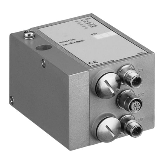
    AVENTICS | DeviceNet | R499050019–BDL–001–AD Gerätebeschreibung Gerätekomponenten 5.2.1 Buskoppler Abb. 2: Übersicht über den Buskoppler 1 LED-Anzeigen für Diagnosemeldungen 2 BTN-Beschriftungsfeld 3 X71 (BUS IN) Anschluss für den Buskoppler zur Ansteuerung der Ventile und der I/O-Module 4 X72 (BUS OUT) Anschluss zur Ansteuerung der Ventile und...
  • Seite 18 AVENTICS | DeviceNet | R499050019–BDL–001–AD Gerätebeschreibung Der Buskoppler ist ausschließlich für den Betrieb als Slave an einem DeviceNet-Bussystem bestimmt. Stationsadresse Die MAC-ID Stationsadresse des Buskopplers wird über die beiden Drehschalter S1 und S2 eingestellt. Baudrate Die max. Baudrate beträgt 500 kBaud.
  • Seite 19: Input-/Output-Module

    AVENTICS | DeviceNet | R499050019–BDL–001–AD Gerätebeschreibung Zertifizierung „Declaration of DeviceNet Conformance The DeviceNet Slave (1 827 030 197) has passed the ODVA DeviceNet Conformance Test at the ODVA Training and Technology Center, Michigan (USA) test laboratory and is declared to be conformant to the composite test revision A18.“...
  • Seite 20: Input-Module

    AVENTICS | DeviceNet | R499050019–BDL–001–AD Gerätebeschreibung 5.2.3 Input-Module Die Input-Module zum Anschluss von elektrischen Sensor- Signalen sind in zwei Ausführungen erhältlich: 8 x M8 (RMV04-8DI_M8) oder 4 x M12, doppelt belegt (RMV04-8DI_M12) Abb. 3: Input-Modul 8fach: RMV04-8DI_M8 (links) und RMV04-8DI_M12 (rechts) 1 Beschriftungsfeld 2 RMV04-8DI_M8 (links): 8 Eingänge auf 8 x M8-Buchsen...
  • Seite 21: Output-Module

    AVENTICS | DeviceNet | R499050019–BDL–001–AD Gerätebeschreibung 5.2.4 Output-Module Die Output-Module zum Anschluss der Aktoren sind in zwei Ausführungen erhältlich: 8 x M8 (RMV04-8DO_M8) oder 4 x M12, doppelt belegt (RMV04-8DO_M12) Abb. 4: Output-Modul 8fach: RMV04-8DO_M8 (links) und RMV04-8DO_M12 (rechts) 1 Beschriftungsfeld...
  • Seite 22: Montage

    AVENTICS | DeviceNet | R499050019–BDL–001–AD Montage Montage Buskoppler am Ventilsystem montieren Sie erhalten Ihr individuell konfiguriertes Ventilsystem der Serie HF03 LG oder HF04 komplett verschraubt mit allen Komponenten: Ventilträger Buskoppler gegebenenfalls I/O-Module Die Montage des gesamten Ventilsystems ist in der beiliegenden Betriebsanleitung für das VS ausführlich beschrieben.
  • Seite 23: Module Beschriften

    AVENTICS | DeviceNet | R499050019–BDL–001–AD Montage Module beschriften Buskoppler Beschriften Sie die für den Buskoppler vorgesehene/ verwendete Adresse am Buskoppler im Feld BTN. Input-/Output-Module Beschriften Sie die Anschlüsse direkt auf den Beschriftungsfeldern der Input-/Output-Module. Die Zuordnung der Beschriftungsfelder zu den Anschlüssen ist durch die Bezeichnung der Anschlüsse gegeben.
  • Seite 24: Allgemeine Hinweise Zum Anschluss Des Buskopplers

    AVENTICS | DeviceNet | R499050019–BDL–001–AD Montage ACHTUNG Falsche Verkabelung Eine falsche oder fehlerhafte Verkabelung führt zu Fehlfunktionen und zur Beschädigung des Bussystems. Halten Sie – sofern nicht anders erwähnt – die Aufbaurichtlinien der ODVA ein. Verwenden Sie nur Kabel, die den Spezifikationen des Feldbusses sowie den Anforderungen bzgl.
  • Seite 25: Buskoppler Als Zwischenstation Anschließen

    AVENTICS | DeviceNet | R499050019–BDL–001–AD Montage Tabelle 5: Belegung X71 (BUS IN) und X72 (BUS OUT) M12, A-codiert BU S I N BUS IN X71 Bedeutung BUS OUT X72 SHIELD Schirm (optional) 1) 2) 24-V-Busversorgung 1) 2) V– GND-Busversorgung CAN_H...
  • Seite 26: Buskoppler Als Letzte Station Anschließen

    AVENTICS | DeviceNet | R499050019–BDL–001–AD Montage unkonfektionierte Kabel und Stecker mit Metallgehäuse verwenden. So schützen Sie die Datenleitungen gegen Störungseinkopplungen. Stellen Sie sicher, dass das Steckergehäuse fest mit dem Buskopplergehäuse verbunden ist. 6.3.3 Buskoppler als letzte Station anschließen 1. Stellen Sie die korrekte Pin-Belegung (siehe Tab. 5 auf Seite 25) Ihrer Steckverbindungen her, wenn Sie eine unkonfektionierte Verkabelung verwenden.
  • Seite 27: Logik- Und Lastversorgung Des Buskopplers Anschließen

    AVENTICS | DeviceNet | R499050019–BDL–001–AD Montage 6.3.4 Logik- und Lastversorgung des Buskopplers anschließen Über den Gerätestecker X10 (POWER) werden die Ventile und der Buskoppler versorgt. Wenn Sie die Logik- und Lastversorgung des Buskopplers anschließen, müssen Sie die in Tab. 6 dargestellte Pin-Belegung sicherstellen.
  • Seite 28: Input-/Output-Module 8Fach Anschließen

    AVENTICS | DeviceNet | R499050019–BDL–001–AD Montage VORSICHT Unsichere Netzteil-Trennung Die 24-V-Versorgung kann aus einem gemeinsamen Netzteil erfolgen. Eine unsichere Netzteil-Trennung kann zur Schädigung des Systems und zu Verletzungen durch Stromschlag führen. Verwenden Sie nur ein Netzteil mit einer sicheren Trennung nach EN 60747, Klassifikation VDE 05551! Damit gelten die entsprechenden Stromkreise als SELV/ PELV- Stromkreise nach IEC 60364-4-41.
  • Seite 29 AVENTICS | DeviceNet | R499050019–BDL–001–AD Montage Input-Modul 1. Verdrahten Sie die Eingänge nach Tab. 8 (DI8_M8) bzw. nach Tab. 9 (DI8_M12). 2. Schließen Sie die elektrischen Ein-/Ausgänge mit M8- oder M12-Kupplungssteckern (Zubehör) an die I/O-Module an. 3. Verschließen Sie nicht belegte Gerätedosen mit der M8- oder M12-Schutzkappe (Zubehör), um die Schutzart IP65 zu...
  • Seite 30: Lastversorgung Des Output-Moduls Anschließen

    AVENTICS | DeviceNet | R499050019–BDL–001–AD Montage Tabelle 10: Belegung der Ausgänge beim Output-Modul 8fach, DO8_M8 Buchse M8x1 Signal Belegung O0…O7 frei nicht belegt Ausgangssignal Ox (Nennspannung 24 V) GND-Bezug des Aktors Gehäuse liegt auf Shield-Potenzial Tabelle 11: Belegung der Ausgänge beim Output-Modul 8fach,...
  • Seite 31: Fe-Anschluss

    AVENTICS | DeviceNet | R499050019–BDL–001–AD Montage Der Anschluss für die Lastversorgung der Output-Module muss folgende Anforderungen erfüllen: Kabelbuchse: M12x1, 4-polig, A-codiert ohne Mittelloch (zur Gewährleistung der Verstecksicherheit) Leitungsquerschnitt: je Ader  0,5 mm Länge: max. 20 m 1. Stellen Sie die korrekte Pin-Belegung (siehe Tab. 12) Ihrer Steckverbindungen her, wenn Sie eine unkonfektionierte Verkabelung verwenden.
  • Seite 32: Inbetriebnahme Und Bedienung

    AVENTICS | DeviceNet | R499050019–BDL–001–AD Inbetriebnahme und Bedienung Abb. 7: FE-Anschluss am VS HF04 mit Buskoppler an EP-Endplatte (1) oder an E-Endplatte (2) Erdung bei VS HF03 LG Bringen Sie die Erdung am FE-Anschluss der E-Endplatte (2) an. Inbetriebnahme und Bedienung Voreinstellungen vornehmen Folgende Voreinstellungen müssen Sie durchführen:...
  • Seite 33: Baudrate Einstellen

    AVENTICS | DeviceNet | R499050019–BDL–001–AD Inbetriebnahme und Bedienung 7.1.1 Baudrate einstellen Die Baudrate wird am Schalter S3 eingestellt (siehe Abb. 8). Er befindet sich unter der PG-Schraubkappe A. Abb. 8: Adressschalter S1, S2 und Mode-Schalter S3 am Buskoppler So stellen Sie die Baudrate ein: 1.
  • Seite 34: Diagnosemeldungen Einstellen

    AVENTICS | DeviceNet | R499050019–BDL–001–AD Inbetriebnahme und Bedienung Vergeben Sie mit S1 und S2 die Stationsadresse von 0 bis 63. Die maximale MAC-ID ist 63! – S1: Zehnerstelle von 0 bis 9 – S2: Einerstelle von 0 bis 9 – S1 + S2 = Stationsadresse...
  • Seite 35 AVENTICS | DeviceNet | R499050019–BDL–001–AD Inbetriebnahme und Bedienung OF F S4 S5 S6 Abb. 9: Schalter S4, S5, S6 für die Zuordnung der Ventilversorgungsspannungen (U Über diese Schalter können die Ventile in Gruppen den Versorgungsspannungen U und U zugeordnet werden.
  • Seite 36 AVENTICS | DeviceNet | R499050019–BDL–001–AD Inbetriebnahme und Bedienung So ordnen Sie die Ventilversorgung zu: 1. Öffnen Sie die untere Schraubkappe B (siehe Abb. 9 auf Seite 35). 2. Ordnen Sie mit Hilfe der Schalter S4, S5 und S6 jeder Ventilgruppe eine der beiden Versorgungsspannungen U oder U zu (siehe Tab.
  • Seite 37 AVENTICS | DeviceNet | R499050019–BDL–001–AD Inbetriebnahme und Bedienung Tabelle 15: Beispiele für die Zuordnung von Schaltern und Ventilversorgung, 24 Ventilspulen Beispiel 1 Beispiel 2 Beispiel 3 Anschlussplatten für beidseitig betätigte Ventile Ventil- Ventil- Ventil- Spule LED Spule LED Spule LED...
  • Seite 38 AVENTICS | DeviceNet | R499050019–BDL–001–AD Inbetriebnahme und Bedienung Tabelle 16: Beispiele für die Zuordnung von Schaltern und Ventilversorgung, 24 Ventilspulen Beispiel 4 Beispiel 5 Beispiel 6 Anschlussplatten für Anschlussplatten für ein- und beidseitig betätigte einseitig betätigte Ventile Ventile Ventil- Ventil-...
  • Seite 39 AVENTICS | DeviceNet | R499050019–BDL–001–AD Inbetriebnahme und Bedienung Tabelle 17: Beispiele für die Zuordnung von Schaltern und Ventilversorgung, 32 Ventilspulen Beispiel 1 Beispiel 2 Beispiel 3 Anschlussplatte für beidseitig betätigte Ventile Ventil- Ventil- Ventil- Spule LED Spule LED Spule LED...
  • Seite 40 AVENTICS | DeviceNet | R499050019–BDL–001–AD Inbetriebnahme und Bedienung Tabelle 18: Beispiele für die Zuordnung von Schaltern und Ventilversorgung, 32 Ventilspulen Beispiel 4 Beispiel 5 Beispiel 6 Anschlussplatte für Anschlussplatte für ein- und beidseitig betätigte einseitig betätigte Ventile Ventile Ventil- Ventil-...
  • Seite 41: Busabschluss Einstellen

    AVENTICS | DeviceNet | R499050019–BDL–001–AD Inbetriebnahme und Bedienung 7.1.5 Busabschluss einstellen Um Leitungsreflexionen zu minimieren und einen definierten Ruhepegel auf der Übertragungsleitung des Buskopplers sicherzustellen, muss die Übertragungsleitung an beiden Enden mit einem Busabschluss versehen werden. Beim Buskoppler ist der Busabschluss im Gerät integriert und kann über den Schalter S8 definiert werden (siehe Abb.
  • Seite 42: Bussystem Konfigurieren

    AVENTICS | DeviceNet | R499050019–BDL–001–AD Inbetriebnahme und Bedienung Bussystem konfigurieren Die im Rahmen der Busmasterkonfiguration für das Gesamtsystem vorzunehmenden Einstellungen sind den bereits beschriebenen Einstellungen am Buskoppler übergeordnet. Alle Leistungsmerkmale und Objekte für die Konfiguration des Buskopplers sind im Electronic Data Sheet (EDS) enthalten.
  • Seite 43: Betriebsverhalten

    AVENTICS | DeviceNet | R499050019–BDL–001–AD Inbetriebnahme und Bedienung Konfigurieren Sie das Bussystem gemäß Ihren Systemanforderungen, den Angaben im EDS, den Vorgaben des Herstellers und allen geltenden technischen Normen, Richtlinien und Sicherheitsvorschriften. Beachten Sie dabei die Dokumentation des Betreibers zur Konfiguration des Busmasters.
  • Seite 44: Test Und Diagnose Am Buskoppler

    AVENTICS | DeviceNet | R499050019–BDL–001–AD Inbetriebnahme und Bedienung Test und Diagnose am Buskoppler 7.5.1 Diagnoseanzeige am Buskoppler ablesen Die LEDs auf der Frontplatte des Buskopplers geben die in Tab. 20 aufgeführten Meldungen wieder. Überprüfen Sie vor Inbetriebnahme und während des Betriebs regelmäßig die Buskopplerfunktionen durch...
  • Seite 45: Sensoren Am Input-Modul Überprüfen

    AVENTICS | DeviceNet | R499050019–BDL–001–AD Inbetriebnahme und Bedienung Tabelle 20: Bedeutung der Diagnose-LEDs am Buskoppler Signal Beschreibung (Duplicate MAC-ID Fehler) blinkt grün Systemhalt durch Ausnahmefehler in Hard-/Firmware (Servicefall) blinkt rot Blinkfrequenz 1: 0,8 s an / 0,2 s aus Blinkfrequenz 2: 0,125 s an / 0,125 s aus 7.5.2...
  • Seite 46: Buskoppler In Betrieb Nehmen

    AVENTICS | DeviceNet | R499050019–BDL–001–AD Inbetriebnahme und Bedienung Abb. 12: LED-Anzeigen am Output-Modul M8 (links) und M12 (rechts) Tabelle 22: Bedeutung der LED-Anzeige am Output-Modul Farbe Bedeutung grün Lastversorgung U vorhanden Diagnose: Überlast/Kurzschluss auf angesteuertem Ausgang O0, O1, O2 oder O3 Lastversorgung U nicht vorhanden (z.
  • Seite 47: Systemhalt

    AVENTICS | DeviceNet | R499050019–BDL–001–AD Inbetriebnahme und Bedienung Sie haben den Busmaster so konfiguriert, dass die Ventile und die Input-Module richtig angesteuert werden. Sie haben den Diagnosetest der Input-/Output-Module durchgeführt (siehe „Test und Diagnose am Buskoppler” auf Seite 44). Die Inbetriebnahme und Bedienung darf nur von einer...
  • Seite 48: Systemhalt Verlassen

    Demontage und Austausch Sie können je nach Bedarf den Buskoppler austauschen oder weitere/andere Input-/Output-Module anbauen. Die Gewährleistung von AVENTICS gilt nur für die ausgelieferte Konfiguration und Erweiterungen, die bei der Konfiguration berücksichtigt wurden. Nach einem Umbau, der über diese Erweiterungen hinausgeht, erlischt die Gewährleistung.
  • Seite 49: Buskoppler Austauschen

    AVENTICS | DeviceNet | R499050019–BDL–001–AD Demontage und Austausch Buskoppler austauschen VORSICHT Anliegende elektrische Spannung und hoher Druck Verletzungsgefahr durch elektrischen Schlag und plötzlichen Druckabbau. Schalten Sie das System drucklos und spannungsfrei. Abb. 13: Buskoppler austauschen, Beispiel 1 Innensechskantschrauben 4 Buskoppler...
  • Seite 50: Input-/Output-Modul(E) Anbauen

    AVENTICS | DeviceNet | R499050019–BDL–001–AD Demontage und Austausch 4. Schieben Sie den neuen Buskoppler (4) auf die Zuganker (5) auf. 5. Stellen Sie sicher, dass – die Zuganker (5) vollständig eingeschraubt und – die Dichtungen (3) richtig eingelegt sind. 6. Schieben Sie zuerst die Input-/Output-Module, falls vorhanden, in der ursprünglichen Reihenfolge und dann die...
  • Seite 51 AVENTICS | DeviceNet | R499050019–BDL–001–AD Demontage und Austausch VORSICHT Offen liegende Ein-/Ausgänge Gefahr von Stromschlag bei Berührung, Kurzschluss und Schädigung des Systems. Verschließen Sie immer nicht benutzte Eingänge bzw. Ausgänge mit M12- und M8-Verschlusskappen (siehe „Ersatzteile und Zubehör” auf Seite 55), um die Schutzart IP65 einzuhalten.
  • Seite 52 AVENTICS | DeviceNet | R499050019–BDL–001–AD Demontage und Austausch Es dürfen insgesamt maximal 6 Module (Input- oder Output-Module) an einem Ventilsystem montiert sein. Beachten Sie die zulässige Strombelastung! Beachten Sie Abb. 14 auf Seite 51. 1. Lösen Sie die E-Endplatte (2) vom Buskoppler (7) oder vom letzten Input-Modul (5)/Output-Modul (4) des Ventilsystems (2 Innensechskantschrauben DIN 912 –...
  • Seite 53: Pflege Und Wartung

    AVENTICS | DeviceNet | R499050019–BDL–001–AD Pflege und Wartung Pflege und Wartung VORSICHT Anliegende elektrische Spannung und hoher Druck Verletzungsgefahr durch elektrischen Schlag und plötzlichen Druckabbau. Schalten Sie das System vor der Durchführung von Pflege- und Wartungsarbeiten druck- und spannungslos. Module pflegen ACHTUNG Beschädigung der Gehäuseoberfläche durch Lösemittel und...
  • Seite 54: Technische Daten

    AVENTICS | DeviceNet | R499050019–BDL–001–AD Technische Daten 10 Technische Daten 10.1 Kenngrößen Allgemein Schutzart nach IP 65 im montierten Zustand EN 60 529 / IEC 529 Umgebungstemperatur  0 C bis +50 C ohne Betauung Elektromagnetische Verträglichkeit Störfestigkeit EN 61131-2, EN 61000-6-2 Störaussendung...
  • Seite 55: Output-Module 8Fach, Rmv04-8Do_M8 Und Rmv04-8Do_M12

    AVENTICS | DeviceNet | R499050019–BDL–001–AD Ersatzteile und Zubehör 10.4 Output-Module 8fach, RMV04-8DO_M8 und RMV04-8DO_M12 Elektrik Ausgänge DIN EN 61131-2 8 digitale Ausgänge Ausgangsspannung Nennwert 24 V Spannungsabfall bei H-Signal  1,5 V Ausgangsstrom Nennwert 0,5 A Aus thermischen Gründen dürfen die Ausgänge nicht längere Zeit über Nennstrom belastet werden.
  • Seite 56: Input-/Output-Modul 8Fach, 8Di/8Do

    AVENTICS | DeviceNet | R499050019–BDL–001–AD Entsorgung 11.1 Input-/Output-Modul 8fach, 8DI/8DO Bestellcode Bestellnummer Input-Modul 8fach (8 x M8) 8DI_M8 R412003489 Input-Modul 8fach (4 x M12) 8DI_M12 R412000871 Output-Modul 8fach (8 x M8) 8DO_M8 R412005968 Output-Modul 8fach (4 x M12) 8DO_M12 R412000870 Zubehör...
  • Seite 57: Anhang

    AVENTICS | DeviceNet | R499050019–BDL–001–AD Anhang 13 Anhang Angaben zur Busmasterkonfiguration mit DeviceNet. 13.1 Electronic Data Sheet (EDS) Das Electronic Data Sheet EDS ist eine vom ODVA spezifizierte ASCII-Datei, in der die Objekte/Leistungsmerkmale eines DeviceNet-Geräts beschrieben sind. Für den Buskoppler mit Feldbusprotokoll DeviceNet gibt es diese Datei mit dem Dateinamen RXyyRMV4.EDS (yy = Version).
  • Seite 58: Devicenet Objects

    AVENTICS | DeviceNet | R499050019–BDL–001–AD Anhang Anschließend kann der Teilnehmer von einem DeviceNet- Master initialisiert werden. Im Fehlerfall wird der Buskoppler in den Systemhalt versetzt (siehe „Systemhalt” auf Seite 47). 13.3 DeviceNet Objects 13.3.1 Identity Object (Class 0x01) Tabelle 23: Class and Instance Attributes – Identity Object...
  • Seite 59: Message Router Object (Class 0X02)

    AVENTICS | DeviceNet | R499050019–BDL–001–AD Anhang Durch den Service Class 0x01, Instance 0x01, Attribute 0x00 für Reset Service wird das Gerät zurückgesetzt. Alle Kommunikationsverbindungen werden abgebrochen. Die Einstellungen an den Dreh- und DIP-Schaltern (MAC-ID, Baudrate, Diagnose) werden neu eingelesen, die Baugruppe wird neu initialisiert.
  • Seite 60 AVENTICS | DeviceNet | R499050019–BDL–001–AD Anhang Tabelle 25: Class and Instance Attributes – DeviceNet Object Object Object Object Objektbeschreibung Class Instance Attribute 0x06 MAC ID Switch Changed 0x00: Seit dem Einschalten/Reset nicht geändert 0x01: Seit dem Einschalten/Reset geändert 0x07 Baud Rate Switch Changed 0x00: Seit dem Einschalten/Reset nicht geändert...
  • Seite 61: Assembly Object (Class 0X04)

    AVENTICS | DeviceNet | R499050019–BDL–001–AD Anhang 13.3.4 Assembly Object (Class 0x04) Tabelle 28: Class and Instance Attributes – Assembly Object Object Object Object Objektbeschreibung Class Instance Attribute 0x04 0x00 0x01 Revision des DeviceNet Objects 0x02 Max Instance maximale Anzahl der Instanzen...
  • Seite 62: Connection Object (Class 0X05)

    AVENTICS | DeviceNet | R499050019–BDL–001–AD Anhang Die Baugruppe RMV04-DN hat: 3 Byte Ausgänge (Consuming Data Bytes), keine Eingänge (Producing Data Bytes). Es besteht jedoch die Möglichkeit, die Diagnosedaten hinter die Eingangsdaten ins Assembly Object zu mappen (Einstellung im Module Control Register MCR). In diesem Fall beträgt die Anzahl der Producing Data Bytes = 1 Byte.
  • Seite 63 AVENTICS | DeviceNet | R499050019–BDL–001–AD Anhang Tabelle 30: Class and Instance Attributes – Connection Object Object Object Object Objektbeschreibung Class Instance Attribute 0x06 Initial_Comm_Characteristics definiert die Message-Gruppe(n) dieser Verbindung (produzierend und konsumierend) 0x07 Produced_Connection_Size maximale Anzahl Byte, die über diese Verbindung gesendet werden können...
  • Seite 64: Discrete Input Point (Class 0X08)

    AVENTICS | DeviceNet | R499050019–BDL–001–AD Anhang X ist wie folgt definiert: Verbindungstyp 0x01 Explicit Messaging Connection 0x02 Poll I/O Connection 0x03 Bit Strobe I/O Connection 0x04 COS / Cyclic I/O Connection 0x05 reserviert Tabelle 31: Class Services – Connection Object...
  • Seite 65 AVENTICS | DeviceNet | R499050019–BDL–001–AD Anhang Max Instance Der Wert des Attributs „Max Instance“ gibt die Anzahl der Eingangspunkte wieder. Dieser Wert ist immer ein Vielfaches von 8 (n x 8 Punkte). Mit 3 Input-Modulen und aktiver Diagnose ergibt sich somit:...
  • Seite 66: Herstellerspezifische Objekte

    AVENTICS | DeviceNet | R499050019–BDL–001–AD Anhang 13.4 Herstellerspezifische Objekte 13.4.1 I/O Data Object (Class 0x64) Tabelle 37: Class and Instance Attributes – I/O Data Object Object Object Object Objektbeschreibung Class Instance Attribute 0x64 0x00 Revision des I/O Data Object Max Instance...
  • Seite 67: Status Object (Class 0X65)

    AVENTICS | DeviceNet | R499050019–BDL–001–AD Anhang Das I/O Data Object ist per Default fest in das Assembly Object gemappt. 13.4.2 Status Object (Class 0x65) Tabelle 39: Class and Instance Attributes – Status Object Object Object Object Objektbeschreibung Class Instance Attribute...
  • Seite 68 AVENTICS | DeviceNet | R499050019–BDL–001–AD Anhang Tabelle 41: Manufacturer Status Register Class 0x65 Inst. 0x01 Attr. 0x65 Default-Wert: 0x0003 14...2 Default-Konfiguration der Diagnose nicht aktiv aktiv Diagnosedaten nicht ins Assembly Object gemappt hinter die Eingangsdaten ins Assembly Object gemappt reserviert...
  • Seite 69 AVENTICS | DeviceNet | R499050019–BDL–001–AD Anhang Diagnostic Data Class Das Objekt Diagnostic Data kann hinter die Eingangsdaten ins 0x65 Inst. 0x02 Attr. 0x66 Assembly Object gemappt werden. Als Diagnosefilter fungieren die Objekte Parameter Data und Device Parameter Data. Tabelle 42: Diagnostic Data Class 0x65 Inst. 0x02 Attr. 0x66 keine Diagnose Überlast Ventiltreiber...
  • Seite 70: Module Control Object (Class 0X66)

    AVENTICS | DeviceNet | R499050019–BDL–001–AD Anhang 13.4.3 Module Control Object (Class 0x66) Tabelle 43: Class and Instance Attributes – Module Control Object Object Object Object Objektbeschreibung Class Instance Attribute 0x66 0x00 0x01 Revision des Module Control Object 0x02 Max Instance...
  • Seite 71: Module Control Register (Mcr)

    AVENTICS | DeviceNet | R499050019–BDL–001–AD Anhang 13.4.4 Module Control Register (MCR) Über das 16 Bit breite Module Control Register kann das Verhalten des Buskopplers verändert werden. Der Default-Wert des Registers (nach Power-on) ist abhängig von der Stellung des DIP-Schalters S3.5 (siehe „Ventilversorgung zuordnen”...
  • Seite 72 AVENTICS | DeviceNet | R499050019–BDL–001–AD Anhang Bit 1 des Module Control Register hat Einfluss auf die E/A- Konfiguration des Buskopplers. Dementsprechend muss der Slave vom DeviceNet-Master mit 0 oder 1 Byte Eingängen konfiguriert werden: MCR Bit 1 = 0 Der Slave muss vom DeviceNet-Master konfiguriert werden mit: –...
  • Seite 73 AVENTICS | DeviceNet | R499050019–BDL–001–AD Anhang Tabelle 46: Device Parameter Data Class 0x66 Inst. 0x02 Attr. 0x66 Überlast Ventiltreiber (Sammelbit) Diagnose gesperrt Diagnose freigegeben Unterspannung Lastversorgung U Diagnose gesperrt Diagnose freigegeben Unterspannung Lastversorgung U Diagnose gesperrt Diagnose freigegeben Lastversorgung U...
  • Seite 74: Sps-Adresszuordnung

    AVENTICS | DeviceNet | R499050019–BDL–001–AD Anhang 13.5 SPS-Adresszuordnung Die zentralen SPS-Adressen werden den dezentralen Ausgängen über einen DeviceNet-Konfigurator zugeordnet. In Tab. 47 auf Seite 74 sehen Sie die Adressbelegung für einen Ventilträger für die Ventilplätze 1 bis 12. Tabelle 47: Adressbelegung auf einem Ventilträger von Byte 0 bis 2...
  • Seite 75: Stichwortverzeichnis

    AVENTICS | DeviceNet | R499050019–BDL–001–AD Stichwortverzeichnis 14 Stichwortverzeichnis Abkürzungen 9 Electronic Data Sheet, (EDS) 57 Abmessungen 22 Elektrischer Anschluss Buskoppler 24 Beschriftung Buskoppler als Buskoppler 23 letzte Station 26 Input-/Output- Buskoppler als Module 23 Zwischenstation 25 Input-/Output- Busabschluss einstellen 41...
  • Seite 76 AVENTICS | DeviceNet | R499050019–BDL–001–AD Stichwortverzeichnis Komponenten Sicherheitshinweise 12, 14 Input-Modul 20 Spannungsversorgung Output-Modul 21 anschließen 30 SPS-Adressen, Zuordnung 74 Mode-Schalter 34 Systemhalt 47 Montage elektrische Anschlüsse 23 Ventilsystem FE-Anschluss 31 Montage 22 Input/Output-Module Ventilversorgung anschließen 28 zuordnen 34 Ventilsystem 22...
  • Seite 77 AVENTICS | DeviceNet | R499050019–BDL–001–AD Contents Contents About This Documentation ......... 81 Documentation validity ............81 Required and supplementary documentation ....81 Presentation of information ..........82 1.3.1 Notes on Safety ..............82 1.3.2 Symbols ................... 83 1.3.3 Abbreviations ................. 83 Notes on Safety ............
  • Seite 78 AVENTICS | DeviceNet | R499050019–BDL–001–AD Contents Commissioning and Operation ......... 105 Making presettings .............. 105 7.1.1 Setting the baud rate ............106 7.1.2 Setting the bus coupler address ........106 7.1.3 Setting the diagnostic messages ........107 7.1.4 Assigning the valve supply ..........107 7.1.5...
  • Seite 79 AVENTICS | DeviceNet | R499050019–BDL–001–AD Contents 13.3 DeviceNet Objects..............131 13.3.1 Identity object (Class 0x01) ..........131 13.3.2 Message router object (class 0x02) ......132 13.3.3 DeviceNet Object (Class 0x03) ........132 13.3.4 Assembly object (class 0x04) ......... 133 13.3.5 Connection object (class 0x05) ........135 13.3.6 Discrete Input Point (Class 0x08) ........
  • Seite 80 AVENTICS | DeviceNet | R499050019–BDL–001–AD Contents...
  • Seite 81: About This Documentation

    AVENTICS | DeviceNet | R499050019–BDL–001–AD About This Documentation About This Documentation Documentation validity This documentation contains important information on the safe and appropriate assembly, operation, and maintenance of the bus coupler and how to remedy simple malfunctions yourself. Read this documentation completely, especially chapter 2 “Notes on Safety”...
  • Seite 82: Presentation Of Information

    AVENTICS | DeviceNet | R499050019–BDL–001–AD About This Documentation Presentation of information To allow you to begin working with the product quickly and safely, uniform safety instructions, symbols, terms, and abbreviations are used in this documentation. For better understanding, these are explained in the following sections.
  • Seite 83: Symbols

    AVENTICS | DeviceNet | R499050019–BDL–001–AD About This Documentation Table 2: Hazard classes according to ANSI Z535.6-2006 Safety sign, signal word Meaning Indicates a hazardous situation which, if not avoided, could result in CAUTION minor or moderate injury. Indicates that damage may be...
  • Seite 84: Notes On Safety

    AVENTICS | DeviceNet | R499050019–BDL–001–AD Notes on Safety Notes on Safety About this section The product has been manufactured according to the accepted rules of current technology. Even so, there is risk of injury and damage to equipment if the following chapter and safety instructions of this documentation are not followed.
  • Seite 85: Improper Use

    Therefore, only use a product in safety-relevant applications if such use is specifically stated and permitted in the product documentation. AVENTICS GmbH is not liable for any damages resulting from improper use. The user alone bears the risks of improper use of the product.
  • Seite 86: General Safety Instructions

    Observe the safety instructions and regulations of the country in which the product is used or operated. Only use AVENTICS products that are in perfect working order. Follow all the instructions on the product. Persons who assemble, operate, disassemble, or maintain AVENTICS products must not consume any alcohol, drugs, or pharmaceuticals that may affect their ability to respond.
  • Seite 87 AVENTICS | DeviceNet | R499050019–BDL–001–AD Notes on Safety The power pack must be fitted with a safe isolation in accordance with EN 60742, VDE 0551 classification. The corresponding electrical circuits are thus SELV/PELV circuits in accordance with IEC 60364-4-41. Switch off the operating voltage before connecting or removing the plugs.
  • Seite 88: Applications

    1 bus coupler with seal and 2 mounting screws 1 set of operating instructions for the bus coupler The VS is individually configured. You can find the exact configuration in the AVENTICS Internet configurator under your order number. Device description The bus coupler makes it possible to control the VS via a fieldbus system.
  • Seite 89: Overview Of The Valve System And Modules

    AVENTICS | DeviceNet | R499050019–BDL–001–AD Device description The following system overview outlines the entire valve system and its components. The VS proper is described in separate operating instructions. Overview of the valve system and modules The valve system consists of the following parts as illustrated in Fig.
  • Seite 90: Device Components

    AVENTICS | DeviceNet | R499050019–BDL–001–AD Device description Device components 5.2.1 Bus coupler Fig. 2: Bus coupler overview 1 LED displays for diagnostic messages 2 Bus slave label 3 X71 (BUS IN) connection for the bus coupler to control valves and the I/O modules...
  • Seite 91 AVENTICS | DeviceNet | R499050019–BDL–001–AD Device description The bus coupler is designed for use as a slave only on a bus system. Station address The bus coupler's MAC ID station address is set using the S1 and S2 rotary switches.
  • Seite 92: Input/Output Modules

    AVENTICS | DeviceNet | R499050019–BDL–001–AD Device description Certification “Declaration of DeviceNet Conformance The DeviceNet slave (1 827 030 197) has passed the ODVA DeviceNet Conformance Test at the ODVA Training and Technology Center, Michigan (USA) test laboratory and is declared to be conformant to the composite test revision A18.”...
  • Seite 93: Input Modules

    AVENTICS | DeviceNet | R499050019–BDL–001–AD Device description 5.2.3 Input modules The input modules used to connect electric sensor signals are available in two versions: 8x M8 (RMV04-8DI_M8) or 4x M12, double-assigned (RMV04-8DI_M12) Fig. 3: 8x input module: RMV04-8DI_M8 (left) and RMV04-8DI_M12 (right)
  • Seite 94: Output Modules

    AVENTICS | DeviceNet | R499050019–BDL–001–AD Device description 5.2.4 Output modules The output modules used to connect the actuators are available in two versions: 8x M8 (RMV04-8DO_M8) or 4x M12, double-assigned (RMV04-8DO_M12) Fig. 4: 8x output module: RMV04-8DO_M8 (left) and RMV04-8DO_M12 (right)
  • Seite 95: Assembly

    AVENTICS | DeviceNet | R499050019–BDL–001–AD Assembly Assembly Assembling the valve system with the bus coupler You will receive your individually configured HF03 LG or HF04 series valve system completely fitted with all components: Valve terminal Bus coupler I/O modules (if needed) The operating instructions accompanying the VS describe in full how to assemble the entire valve system.
  • Seite 96: Labeling The Module

    AVENTICS | DeviceNet | R499050019–BDL–001–AD Assembly Labeling the module Bus coupler Inscribe the address provided/used for the bus coupler on the bus coupler in the BTN field. Input/output modules Label the connections directly on the labels of the input/ output modules.
  • Seite 97: General Notes On Connecting The Bus Coupler

    AVENTICS | DeviceNet | R499050019–BDL–001–AD Assembly NOTICE Faulty wiring Faulty wiring can lead to malfunctions as well as damage to the bus system. Unless otherwise stipulated, comply with the ODVA construction and design directives. Only a cable that meets the fieldbus specifications as well as the connection speed and length requirements should be used.
  • Seite 98: Connecting The Bus Coupler As An Intermediate Station

    AVENTICS | DeviceNet | R499050019–BDL–001–AD Assembly Table 5: Assignment X71 (BUS IN) and X72 (BUS OUT), M12, A-coded BU S I N Bus IN X71 Meaning BUS OUT X72 SHIELD Shield (optional) 1) 2) 24 V bus supply 1) 2) V–...
  • Seite 99: Connecting The Bus Coupler As A Final Station

    AVENTICS | DeviceNet | R499050019–BDL–001–AD Assembly data lines from terminal interference. Ensure that the plug housing is securely fitted to the bus coupler housing. 6.3.3 Connecting the bus coupler as a final station 1. Set up the correct pin assignment (see Tab. 5 on page 98) on the plug connections if you do not use pre-assembled wiring.
  • Seite 100: Connecting The Bus Coupler Logic And Load Supply

    AVENTICS | DeviceNet | R499050019–BDL–001–AD Assembly 6.3.4 Connecting the bus coupler logic and load supply Power is supplied to the valves and the bus coupler via the X10 (POWER) plug. When connecting the logic and load supply of the bus coupler, ensure pin assignment according to Tab.
  • Seite 101: Connecting The 8X Input/Output Modules

    AVENTICS | DeviceNet | R499050019–BDL–001–AD Assembly CAUTION Unsafe power pack isolation A standard power pack can supply all system components with 24 V. An unsafe power pack isolation can damage the system and cause injuries arising from electric shock. Only use a power pack with safe isolation according to...
  • Seite 102 AVENTICS | DeviceNet | R499050019–BDL–001–AD Assembly Input module 1. Wire the inputs according to Tab. 8 (DI8_M8) or Tab. 9 (DI8_M12). 2. Connect the electrical inputs/outputs to the I/O modules with M8 or M12 coupling plugs (accessories). 3. To ensure the IP65 protection class, close unused sockets with M8 or M12 protective caps (accessories).
  • Seite 103: Connecting The Output Module Load Supply

    AVENTICS | DeviceNet | R499050019–BDL–001–AD Assembly Table 10: Output assignment for 8x output module, DO8_M8, M8x1 socket Signal Assignment O0…O7 Free Not connected Ox output signal (nominal voltage 24 V) GND actuator reference Housing Connected to shield potential Table 11:...
  • Seite 104: Fe Connection

    AVENTICS | DeviceNet | R499050019–BDL–001–AD Assembly The connection for the output module load supply must meet the following requirements: Cable socket: M12x1, 4-pin, A-coded without center hole (to ensure correct plug-in connection) Cable cross-section: per wire ≥ 0.5 mm Length: Max. 20 m 1.
  • Seite 105: Commissioning And Operation

    AVENTICS | DeviceNet | R499050019–BDL–001–AD Commissioning and Operation Fig. 7: FE connection on the VS HF04 with bus coupler on the EP end plate (1) or an E end plate (2) VS HF03 LG grounding Affix the grounding on the FE connection of the E end plate (2).
  • Seite 106: Setting The Baud Rate

    AVENTICS | DeviceNet | R499050019–BDL–001–AD Commissioning and Operation 7.1.1 Setting the baud rate The baud rate is set on switch S3 (see Fig. 8). The switch can be found under the PG screw cap A. Fig. 8: S1, S2 address switches and S3 mode switch on the bus coupler How to set the baud rate: 1.
  • Seite 107: Setting The Diagnostic Messages

    AVENTICS | DeviceNet | R499050019–BDL–001–AD Commissioning and Operation Assign the station address from 0 to 63 using S1 and S2. The maximum MAC ID is 63! – S1: Tens digit from 0 to 9 – S2: Unit digit from 0 to 9 –...
  • Seite 108 AVENTICS | DeviceNet | R499050019–BDL–001–AD Commissioning and Operation OF F S4 S5 S6 Fig. 9: S4, S5, and S6 switches for assigning valve supply voltages This switch allows valves to be assigned in groups to supply voltages U and U When delivered, all valves are assigned to the U voltage.
  • Seite 109 AVENTICS | DeviceNet | R499050019–BDL–001–AD Commissioning and Operation Examples for the assignment of the S4, S5 and S6 switches and the supply of assembled valves for 24 valve output stages can be found in Tab. 15 and Tab. 16 on pages 110, 111 and for 32 valve output stages in Tab.
  • Seite 110 AVENTICS | DeviceNet | R499050019–BDL–001–AD Commissioning and Operation Table 15: Examples for assignment of switches and valve supply, 24 valve coils Example 1 Example 2 Example 3 Subbases for double solenoid valves Valve Valve Valve Sol. LED Sol. LED Sol. LED...
  • Seite 111 AVENTICS | DeviceNet | R499050019–BDL–001–AD Commissioning and Operation Table 16: Examples for assignment of switches and valve supply, 24 valve coils Example 4 Example 5 Example 6 Subbases for single Subbases for single and double solenoid valves solenoid valves Valve...
  • Seite 112 AVENTICS | DeviceNet | R499050019–BDL–001–AD Commissioning and Operation Table 17: Examples for assignment of switches and valve supply, 32 valve coils Example 1 Example 2 Example 3 Subbase for double solenoid valves Valve Valve Valve Sol. LED Sol. LED Sol. LED...
  • Seite 113 AVENTICS | DeviceNet | R499050019–BDL–001–AD Commissioning and Operation Table 18: Examples for assignment of switches and valve supply, 32 valve coils Example 4 Example 5 Example 6 Subbase for single Subbase for single and double solenoid valves solenoid valves Valve...
  • Seite 114: Setting The Bus Terminator

    AVENTICS | DeviceNet | R499050019–BDL–001–AD Commissioning and Operation 7.1.5 Setting the bus terminator In order to minimize line reflections and to ensure a defined rest level on the bus coupler transfer line, a bus terminator has to be fitted on both ends of the transfer line.
  • Seite 115: Configuring The Bus System

    AVENTICS | DeviceNet | R499050019–BDL–001–AD Commissioning and Operation Configuring the bus system The settings to be made for the overall system during the bus configuration are superior to the already described settings on the bus coupler. All the performance data and objects for the configuration of the bus coupler are listed in the Electronic Data Sheet (EDS).
  • Seite 116: Operating Behavior

    AVENTICS | DeviceNet | R499050019–BDL–001–AD Commissioning and Operation Configure the bus system in accordance with your system requirements, the specifications in the EDS, the manufacturer’s specifications, and all valid technical standards, directives, and safety regulations. Take the operator’s documentation on configuring the bus master into account.
  • Seite 117: Testing And Diagnosis On The Bus Coupler

    AVENTICS | DeviceNet | R499050019–BDL–001–AD Commissioning and Operation Testing and diagnosis on the bus coupler 7.5.1 Reading the bus coupler diagnostic display The LEDs on the front panel of the bus coupler show the messages from Tab. 20. Before commissioning and during operation, regularly check bus coupler functions by reading the diagnostic displays.
  • Seite 118: Check Sensors On The Input Module

    AVENTICS | DeviceNet | R499050019–BDL–001–AD Commissioning and Operation Table 20: Definitions for diagnostic LEDs on the bus coupler Signal Description (Duplicate MAC ID error) Flashes green System stopped through exception error in hard/firmware (service case) Flashes red Blink frequency 1: 0.8 s on/0.2 s off Blink frequency 2: 0.125 s on/0.125 s off...
  • Seite 119: Check Actuators On Output Module

    AVENTICS | DeviceNet | R499050019–BDL–001–AD Commissioning and Operation 7.5.3 Check actuators on output module Before commissioning, check the actuator function and the method of operation using the LED displays on the output module (see Tab. 22). Fig. 12: LED displays on the M8 output module (left) and M12 (right)
  • Seite 120: Commissioning The Bus Coupler

    AVENTICS | DeviceNet | R499050019–BDL–001–AD Commissioning and Operation Commissioning the bus coupler Before commissioning the system, the following steps must have been carried out and completed: You have assembled the valve terminal and the bus coupler (see “Assembling the valve system with the bus coupler” on page 95).
  • Seite 121: System Stop

    Disassembly and Exchange You can either exchange the bus coupler or connect additional input/output modules as needed. The AVENTICS warranty only applies to the delivered configuration and extensions taken into account in the configuration. The warranty no longer applies after a conversion that exceeds these extensions.
  • Seite 122: Exchanging The Bus Coupler

    AVENTICS | DeviceNet | R499050019–BDL–001–AD Disassembly and Exchange Exchanging the bus coupler CAUTION Applied voltage and high pressure! Danger of injury from electric shocks and sudden pressure drops. Make sure that the system is not under voltage or pressure. Fig. 13: Exchanging the bus coupler, example...
  • Seite 123: Mounting Input/Output Module(S)

    AVENTICS | DeviceNet | R499050019–BDL–001–AD Disassembly and Exchange 5. Make sure that – the tie rods (5) are fixed flush to the surface and – the seals (3) have been inserted correctly. 6. Push the input/output modules (if applicable) in the original...
  • Seite 124 AVENTICS | DeviceNet | R499050019–BDL–001–AD Disassembly and Exchange Fig. 14: Mounting input/output module, example with VS HF03 LG (A) and VS HF04 (B) 1 Hexagonal socket-head screws 5 Input module 2 E end plate 6 Tie rod 3 Seal 7 Bus coupler...
  • Seite 125 AVENTICS | DeviceNet | R499050019–BDL–001–AD Disassembly and Exchange 3. Attach the (additional) input (5) or output module (4) to the tie rods (6). – Make sure the seals (3) have been correctly inserted and that the contacts have been properly connected.
  • Seite 126: Care And Maintenance

    AVENTICS | DeviceNet | R499050019–BDL–001–AD Care and Maintenance Care and Maintenance CAUTION Applied voltage and high pressure! Danger of injury from electric shocks and sudden pressure drops. Turn off the system’s pressure and voltage before carrying out any service and maintenance work.
  • Seite 127: Technical Data

    AVENTICS | DeviceNet | R499050019–BDL–001–AD Technical Data 10 Technical Data 10.1 Characteristics General Protection class according to IP65 when assembled EN 60529/IEC 529 Ambient temperature  0 C to +50 C, without condensation Electromagnetic compatibility Interference immunity EN 61131-2, EN 61000-6-2...
  • Seite 128: 8X Output Modules, Rmv04-8Do_M8 And Rmv04-8Do_M12

    AVENTICS | DeviceNet | R499050019–BDL–001–AD Spare parts and accessories 10.4 8x output modules, RMV04-8DO_M8 and RMV04-8DO_M12 Electrics Outputs DIN EN 61131-2 8 digital outputs Output voltage Nominal value 24 V H signal voltage drop  1.5 V Output current Nominal value 0.5 A...
  • Seite 129: 8X Input/Output Module, 8Di/8Do

    AVENTICS | DeviceNet | R499050019–BDL–001–AD Disposal 11.1 8x input/output module, 8DI/8DO Order code Order number 8x input module (8x M8) 8DI_M8 R412003489 8x input module (4x M12) 8DI_M12 R412000871 8x output module (8x M8) 8DO_M8 R412005968 8x output module (4x M12)
  • Seite 130: Appendix

    AVENTICS | DeviceNet | R499050019–BDL–001–AD Appendix 13 Appendix Information on the bus master configuration with DeviceNet 13.1 Electronic Data Sheet (EDS) The EDS Electronic Data Sheet is an ASCII file specified by ODVA that describes the objects/performance data of the DeviceNet.
  • Seite 131: Devicenet Objects

    AVENTICS | DeviceNet | R499050019–BDL–001–AD Appendix 13.3 DeviceNet Objects 13.3.1 Identity object (Class 0x01) Table 23: Class and instance attributes – identity object Object Object Object Object description class instance attribute 0x01 0x00 0x01 Revision of the Identity Object 0x01...
  • Seite 132: Message Router Object (Class 0X02)

    AVENTICS | DeviceNet | R499050019–BDL–001–AD Appendix 13.3.2 Message router object (class 0x02) – Class and instance attributes: No attributes are supported for this object. – Common services: No services are supported for this object. 13.3.3 DeviceNet Object (Class 0x03) Table 25: Class and Instance Attributes –...
  • Seite 133: Assembly Object (Class 0X04)

    AVENTICS | DeviceNet | R499050019–BDL–001–AD Appendix Table 25: Class and Instance Attributes – DeviceNet Object Object Object Object Object description class instance attribute 0x08 MAC ID switch value See chapter “Setting the bus coupler address” on page 106 for more information.
  • Seite 134 AVENTICS | DeviceNet | R499050019–BDL–001–AD Appendix Table 28: Class and instance attributes – assembly object Object Object Object Object description class instance attribute 0x04 0x03 Assembly object 2 Data of the objects to be received (consuming data bytes) with the...
  • Seite 135: Connection Object (Class 0X05)

    AVENTICS | DeviceNet | R499050019–BDL–001–AD Appendix 13.3.5 Connection object (class 0x05) Table 30: Class and Instance Attributes – Connection Object Object Object Object Object description class instance attribute 0x05 0x00 0x01 Revision of the connection object 0x05 0x01 State (see...
  • Seite 136 AVENTICS | DeviceNet | R499050019–BDL–001–AD Appendix Table 30: Class and Instance Attributes – Connection Object Object Object Object Object description class instance attribute 0x05 0x0C Watchdog_Timeout_action (see Defines how inactivity and watchdog below) events should be handled 0x0D Produced_Connection_Path_Length Number of bytes in the attribute...
  • Seite 137: Discrete Input Point (Class 0X08)

    AVENTICS | DeviceNet | R499050019–BDL–001–AD Appendix 13.3.6 Discrete Input Point (Class 0x08) Table 33: Class and Instance Attributes – Discrete Input Point Object Object Object Object description class instance attribute 0x08 0x00 0x01 Revision of the DeviceNet object 0x02 Max. instance...
  • Seite 138: Manufacturer-Specific Objects

    AVENTICS | DeviceNet | R499050019–BDL–001–AD Appendix Table 36: Common Services – Discrete Input Point Service code Service name 0x0E Get attribute single 0x10 Set attribute single Max. instance The value of the “Max. instance” attribute represents the number of output points. The value is always a multiple of 8 (n ×...
  • Seite 139: Status Object (Class 0X65)

    AVENTICS | DeviceNet | R499050019–BDL–001–AD Appendix Table 37: Class and instance attributes – I/O data object Object Object Object Object description class instance attribute 0x64 0x04 0x64 + i Input data (word) Input data as individual word i = 0...n –> word 0...n of the input...
  • Seite 140 AVENTICS | DeviceNet | R499050019–BDL–001–AD Appendix Table 39: Class and Instance Attributes – Status Object (Cont.) Object Object Object Object description class instance attribute 0x65 Diagnostic status Output data as individual byte with 24 bit outputs: i = 0...2 –> byte 0...2 of the output data 0x66...
  • Seite 141 AVENTICS | DeviceNet | R499050019–BDL–001–AD Appendix Diagnostic status 0x00 no active diagnosis 0x01 diagnosis is ready (group diagnosis flag) Configuration length, With the assembly, these objects do not have a function. The configuration data following values are produced when reading out:...
  • Seite 142: Module Control Object (Class 0X66)

    AVENTICS | DeviceNet | R499050019–BDL–001–AD Appendix 13.4.3 Module control object (class 0x66) Table 43: Class and instance attributes – module control object Object Object Object Object description class instance attribute 0x66 0x00 0x01 Revision of the module control object 0x02 Max.
  • Seite 143: Module Control Register (Mcr)

    AVENTICS | DeviceNet | R499050019–BDL–001–AD Appendix 13.4.4 Module Control Register (MCR) The behavior of the bus coupler can be changed with the 16-bit wide Module Control Register. The default value of the register (after power-on) depends on the position of the S3.5 DIP switch 5 (see “Assigning the valve supply”...
  • Seite 144 AVENTICS | DeviceNet | R499050019–BDL–001–AD Appendix Bit 1 of the Module Control Register has an influence on the I/O configuration of the bus coupler. Accordingly, the slave from the DeviceNet master must be configured with 0 or 1 byte inputs:...
  • Seite 145 AVENTICS | DeviceNet | R499050019–BDL–001–AD Appendix Table 46: Device parameter data class 0x66 inst. 0x02 attr. 0x66 Valve driver overload (group bit) Diagnosis blocked Diagnosis enabled Low load supply voltage U Diagnosis blocked Diagnosis enabled Low load supply voltage U...
  • Seite 146: Plc Address Assignment

    AVENTICS | DeviceNet | R499050019–BDL–001–AD Appendix 13.5 PLC address assignment The central PLC addresses are assigned to the decentralized outputs via a DeviceNet configurator. In Tab. 47 on page 146, you can find the address assignment for a valve terminal for the valve positions 1 to 12.
  • Seite 147: Index

    AVENTICS | DeviceNet | R499050019–BDL–001–AD Index 14 Index Abbreviations 83 DeviceNet Certification 92 Assembly Connecting the input/ Configuration 115 output modules 101 Objects 131 Electrical Regulations 91 connections 96 Diagnosis, display 117 FE connection 104 Dimensions 95 Valve system 95...
  • Seite 148 AVENTICS | DeviceNet | R499050019–BDL–001–AD Index Labeling PLC addresses, assignment 146 Bus coupler 96 Input/output Plug, X10 (POWER) 100 modules 96 Presetting Assigning the valve supply 107 Mode switch 107 Baud rate and diagnosis 106 Bus terminator 114 Notes on Safety 86, 87...
  • Seite 149 AVENTICS | DeviceNet | R499050019–BDL–001–AD Sommaire Sommaire A propos de cette documentation ......153 Validité de la documentation..........153 Documentations nécessaires et complémentaires..153 Présentation des informations......... 154 1.3.1 Consignes de sécurité ............154 1.3.2 Symboles ................155 1.3.3 Abréviations ................. 155 Consignes de sécurité...
  • Seite 150 AVENTICS | DeviceNet | R499050019–BDL–001–AD Sommaire 6.3.4 Raccordement de l’alimentation des circuits logiques et des distributeurs du coupleur de bus ..173 6.3.5 Raccordement des modules d’entrée / de sortie 8x ... 175 6.3.6 Raccordement de l’alimentation des distributeurs du module de sortie ............177 6.3.7...
  • Seite 151 AVENTICS | DeviceNet | R499050019–BDL–001–AD Sommaire Pièces de rechange et accessoires ......204 11.1 Module d’entrée / de sortie 8x, 8DI/8DO ....... 205 11.2 Connecteur pour coupleur de bus et module de sortie.. 205 Elimination des déchets ........... 205 Annexe ................ 206 13.1...
  • Seite 152 AVENTICS | DeviceNet | R499050019–BDL–001–AD Sommaire...
  • Seite 153: Propos De Cette Documentation

    Documentation du système de R412015493 Instructions distributeurs HF04 D-SUB Modes d’emploi pour les autres système de distributeurs Documentation de l’installation Pour de plus amples informations concernant les composants, consulter le catalogue de produits en ligne d’AVENTICS sur le site www.aventics.com/pneumatics-catalog.
  • Seite 154: Présentation Des Informations

    AVENTICS | DeviceNet | R499050019–BDL–001–AD A propos de cette documentation Présentation des informations Afin de pouvoir travailler rapidement et en toute sécurité avec ce produit, cette documentation contient des consignes de sécurité, symboles, termes et abréviations standardisés. Ces derniers sont expliqués dans les paragraphes suivants.
  • Seite 155: Symboles

    AVENTICS | DeviceNet | R499050019–BDL–001–AD A propos de cette documentation Tableau 2 : Classes de dangers selon la norme ANSI Z535.6-2006 Signal de danger, mot-clé Signification Signale une situation dangereuse susceptible d’entraîner des blessures légères à modérées si le ATTENTION danger n’est pas évité.
  • Seite 156: Consignes De Sécurité

    AVENTICS | DeviceNet | R499050019–BDL–001–AD Consignes de sécurité Consignes de sécurité A propos de ce chapitre Le produit a été fabriqué selon les règles techniques généralement reconnues. Des dommages matériels et corporels peuvent néanmoins survenir si ce chapitre de même que les consignes de sécurité...
  • Seite 157: Utilisation Non Conforme

    AVENTICS GmbH décline toute responsabilité en cas de dommages résultant d’une utilisation non conforme. Toute utilisation non conforme est aux risques et périls de l’utilisateur.
  • Seite 158: Consignes Générales De Sécurité

    Il n’est admis de mettre le produit en service que lorsqu’il a été constaté que le produit final (par exemple une machine ou une installation) dans lequel les produits AVENTICS sont utilisés satisfait bien aux dispositions du pays d’utilisation, prescriptions de sécurité et normes de l’application.
  • Seite 159: Consignes De Sécurité Selon Le Produit Et La Technique

    AVENTICS | DeviceNet | R499050019–BDL–001–AD Consignes de sécurité Consignes de sécurité selon le produit et la technique Ne surcharger en aucun cas l’appareil de manière mécanique. Ne jamais y déposer d’objets. S’assurer que l’alimentation en tension se situe dans la plage de tolérance indiquée pour les modules.
  • Seite 160: Domaines D'application

    AVENTICS | DeviceNet | R499050019–BDL–001–AD Domaines d’application L’appareil est soumis à l’indice de protection IP 65. Avant la mise en service, s’assurer que tous les joints et bouchons des raccords enfichables sont étanches, afin d’éviter que des liquides ou des corps solides ne pénètrent dans l’appareil.
  • Seite 161: Fourniture

    AVENTICS | DeviceNet | R499050019–BDL–001–AD Fourniture Fourniture Sont compris dans la fourniture : 1 système de distributeurs conformément à la configuration et à la commande 1 mode d’emploi du système de distributeurs 1 mode d’emploi du coupleur de bus La fourniture d’un jeu de pièces pour un coupleur de bus...
  • Seite 162: Vue D'ensemble Du Système De Distributeurs Et Des Modules

    AVENTICS | DeviceNet | R499050019–BDL–001–AD Description de l’appareil Vue d’ensemble du système de distributeurs et des modules Selon la commande, le système de distributeurs est constitué des composants représentés à la fig. 1 : Fig. 1 : Vue d’ensemble exemple de configuration du coupleur de bus avec modules E/S et VS monté...
  • Seite 163: Composants

    AVENTICS | DeviceNet | R499050019–BDL–001–AD Description de l’appareil Composants 5.2.1 Coupleur de bus Fig. 2 : Vue d’ensemble du coupleur de bus 1 Affichages LED pour notifications de diagnostic. 2 Case d’inscription BTN 3 Connexion X71 (BUS IN) pour le coupleur de bus destiné à...
  • Seite 164 AVENTICS | DeviceNet | R499050019–BDL–001–AD Description de l’appareil Le coupleur de bus est exclusivement destiné à fonctionner en tant qu’esclave dans un système bus DeviceNet. Adresse de la station L’adresse de la station MAC-ID du coupleur de bus est paramétrée par les deux commutateurs rotatifs S1 et S2.
  • Seite 165: Modules D'entrée/De Sortie

    AVENTICS | DeviceNet | R499050019–BDL–001–AD Description de l’appareil Certification « Declaration of DeviceNet Conformance The DeviceNet Slave (1 827 030 197) has passed the ODVA DeviceNet Conformance Test at the ODVA Training and Technology Center, Michigan (USA) test laboratory and is declared to be conformant to the composite test revision A18.
  • Seite 166: Modules D'entrée

    AVENTICS | DeviceNet | R499050019–BDL–001–AD Description de l’appareil 5.2.3 Modules d’entrée Les modules d’entrée destinés à la connexion des signaux électriques de capteurs sont disponibles en deux versions : 8 x M8 (RMV04-8DI_M8) ou 4 x M12, double affectation (RMV04-8DI_M12) Fig.
  • Seite 167: Modules De Sortie

    AVENTICS | DeviceNet | R499050019–BDL–001–AD Description de l’appareil 5.2.4 Modules de sortie Les modules de sortie destinés à la connexion des actionneurs sont disponibles en deux versions : 8 x M8 (RMV04-8DO_M8) ou 4 x M12, double affectation (RMV04-8DO_M12) Fig. 4 : Module de sortie 8x : RMV04-8DO_M8 (à gauche) et RMV04-8DO_M12 (à droite) 1 Case d’inscription...
  • Seite 168: Montage

    AVENTICS | DeviceNet | R499050019–BDL–001–AD Montage Montage Montage du coupleur de bus sur le système de distributeurs Le système de distributeurs de la série HF03 LG ou HF04 est livré selon la configuration souhaitée, complètement vissé avec tous les composants :...
  • Seite 169: Inscription Des Modules

    AVENTICS | DeviceNet | R499050019–BDL–001–AD Montage Avec chaque module d’entrée/de sortie, le système de distributeurs est allongé de 60 mm (60 x m). L’embase terminale E a une profondeur de montage de 18 mm. Inscription des modules Coupleur de bus Inscrire l’adresse prévue / utilisée pour le coupleur de bus...
  • Seite 170: Raccordement Électrique Du Coupleur De Bus

    AVENTICS | DeviceNet | R499050019–BDL–001–AD Montage Raccordement électrique du coupleur de bus ATTENTION Tension électrique Risque de blessure dû à une électrocution. Toujours mettre la partie concernée de l’installation hors tension et hors pression, avant de procéder au raccordement électrique des modules sur le porte- distributeurs.
  • Seite 171: Remarques Générales Concernant Le Raccordement Du Coupleur De Bus

    AVENTICS | DeviceNet | R499050019–BDL–001–AD Montage 6.3.1 Remarques générales concernant le raccordement du coupleur de bus Pour raccorder les modules, utiliser des raccords enfichables et des câbles confectionnés. Lors de l’utilisation de raccords enfichables et de câbles non confectionnés, respecter l’affectation des broches représentée dans le Tab.
  • Seite 172: Raccordement Du Coupleur De Bus En Tant Que Station Intermédiaire

    AVENTICS | DeviceNet | R499050019–BDL–001–AD Montage 6.3.2 Raccordement du coupleur de bus en tant que station intermédiaire 1. Effectuer l’affectation correcte des broches (voir Tab. 5 à la page 171) des raccords enfichables, lors de l’utilisation de câbles non confectionnés.
  • Seite 173: Raccordement De L'alimentation Des Circuits Logiques Et Des Distributeurs Du Coupleur De Bus

    AVENTICS | DeviceNet | R499050019–BDL–001–AD Montage 6. Munir la prise X72 (BUS OUT) d’un capuchon de protection (2). 7. En cas d’utilisation de câbles et de connecteurs non confectionnés avec boîtier métallique, raccorder le blindage directement sur le boîtier du connecteur (boîtier CEM) aux deux côtés du câble bus.
  • Seite 174 AVENTICS | DeviceNet | R499050019–BDL–001–AD Montage Le câble pour l’alimentation des distributeurs doit répondre aux exigences suivantes : Douille de câble : 4 pôles, codage A sans trou central Section de câble : par conducteur 0,5 mm Longueur : max. 20 m Tableau 7 : Puissance absorbée à...
  • Seite 175: Raccordement Des Modules D'entrée / De Sortie 8X

    AVENTICS | DeviceNet | R499050019–BDL–001–AD Montage Préparer l’alimentation électrique conformément au Tab. 7 à la page 174. Sélectionner les sections de câble en fonction des longueurs de câble et des courants émergents. 6.3.5 Raccordement des modules d’entrée / de sortie 8x ATTENTION Pièces conductrices de courant librement accessibles...
  • Seite 176 AVENTICS | DeviceNet | R499050019–BDL–001–AD Montage Tableau 9 : Affectation des entrées pour le module d’entrée 8x, DI8_M12, douille M12x1, codé A Broche Signal Affectation CAPTEUR+ Alimentation capteur + 24 V I1, I3, I5 ou I7 Signal capteur CAPTEUR– Potentiel de référence GND...
  • Seite 177: Raccordement De L'alimentation Des Distributeurs Du Module De Sortie

    AVENTICS | DeviceNet | R499050019–BDL–001–AD Montage REMARQUE Somme des intensités trop élevée Chaque sortie est prévue pour un courant permanent de maximum 0,5 A. Des charges électriques supérieures à 0,5 A par sortie peuvent entraîner des restrictions du fonctionnement. Veiller à ce que la charge électrique ne soit pas supérieure à...
  • Seite 178: Raccord Fe

    AVENTICS | DeviceNet | R499050019–BDL–001–AD Montage 6.3.7 Raccord FE Mise à la terre Pour dissiper les interférences CEM, relier le raccord FE (1) pour VS HF04 avec la mise à terre sur l’embase terminale EP du VS par un circuit à basse impédance.
  • Seite 179: Mise En Service Et Utilisation

    AVENTICS | DeviceNet | R499050019–BDL–001–AD Mise en service et utilisation Mise en service et utilisation Définition des paramétrages préalables Effectuer les préréglages suivants : Paramétrage du débit en bauds Réglage de l’adresse sur le coupleur de bus Paramétrage des notifications de diagnostic Affectation de l’alimentation du distributeur...
  • Seite 180: Réglage De L'adresse Sur Le Coupleur De Bus

    AVENTICS | DeviceNet | R499050019–BDL–001–AD Mise en service et utilisation Procéder comme suit pour paramétrer le débit en bauds : 1. Ouvrir le capuchon fileté PG supérieur A. 2. Paramétrer le débit en bauds (vitesse de transmission) à l’aide des commutateurs S3/1 à S3/3 selon les indications du Tab. 13.
  • Seite 181: Paramétrage Des Notifications De Diagnostic

    AVENTICS | DeviceNet | R499050019–BDL–001–AD Mise en service et utilisation 7.1.3 Paramétrage des notifications de diagnostic Le commutateur de mode S3 pour le paramétrage des notifications de diagnostic se trouve sous le vissage PG A (voir fig. 8 à la page 179).
  • Seite 182 AVENTICS | DeviceNet | R499050019–BDL–001–AD Mise en service et utilisation Ces commutateurs permettent d’affecter les distributeurs par groupes aux tensions d’alimentation U et U A la livraison, tous les distributeurs sont affectés à la tension U Tableau 14 : Affectation des commutateurs S4, S5 et S6...
  • Seite 183 AVENTICS | DeviceNet | R499050019–BDL–001–AD Mise en service et utilisation distributeurs pouvant être commandées dans les Tab. 17 et Tab. 18 aux pages 186 et 187 (exemples 1 à 3 / exemples 4 à 6). Les exemples de combinaisons suivants y sont índiqués : Exemples Embases utilisées...
  • Seite 184 AVENTICS | DeviceNet | R499050019–BDL–001–AD Mise en service et utilisation Tableau 15 : Exemples pour l’affectation de commutateurs et l’alimentation des distributeurs, 24 bobines de distributeur Exemple 1 Exemple 2 Exemple 3 Embases pour distributeurs bistables Empl. Empl. Empl. Bobine LED...
  • Seite 185 AVENTICS | DeviceNet | R499050019–BDL–001–AD Mise en service et utilisation Tableau 16 : Exemples pour l’affectation de commutateurs et l’alimentation des distributeurs, 24 bobines de distributeur Exemple 4 Exemple 5 Exemple 6 Embases pour Embases pour distributeurs monostables et distributeurs...
  • Seite 186 AVENTICS | DeviceNet | R499050019–BDL–001–AD Mise en service et utilisation Tableau 17 : Exemples pour l’affectation de commutateurs et l’alimentation des distributeurs, 32 bobines de distributeur Exemple 1 Exemple 2 Exemple 3 Embase pour distributeurs bistables Empl. Empl. Empl. Bobine LED...
  • Seite 187 AVENTICS | DeviceNet | R499050019–BDL–001–AD Mise en service et utilisation Tableau 18 : Exemples pour l’affectation de commutateurs et l’alimentation des distributeurs, 32 bobines de distributeur Exemple 4 Exemple 5 Exemple 6 Embase pour distributeurs Embase pour distributeurs monostables et bistables monostables Empl.
  • Seite 188: Paramétrage De Terminaison Bus

    AVENTICS | DeviceNet | R499050019–BDL–001–AD Mise en service et utilisation 7.1.5 Paramétrage de terminaison bus Afin de minimiser les réflexions de puissance et de garantir une fréquence de repos défini sur le câble de transmission du coupleur de bus, le câble de transmission doit être muni d’une terminaison bus aux deux extrémités.
  • Seite 189: Configuration Du Système Bus

    AVENTICS | DeviceNet | R499050019–BDL–001–AD Mise en service et utilisation Configuration du système bus Les paramétrages à réaliser dans le cadre de la configuration du maître bus pour l’ensemble du système prévalent sur les paramétrages déjà décrits effectués sur le coupleur de bus.
  • Seite 190: Comportement En Service

    AVENTICS | DeviceNet | R499050019–BDL–001–AD Mise en service et utilisation Configurer le système bus conformément aux exigences du système, aux indications du fabricant et à toutes les normes techniques, directives et mesures de sécurité en vigueur. Pour configurer le maître bus, respecter la documentation de l’exploitant.
  • Seite 191: Test Et Diagnostic Du Coupleur De Bus

    AVENTICS | DeviceNet | R499050019–BDL–001–AD Mise en service et utilisation Test et diagnostic du coupleur de bus 7.5.1 Lecture de l’affichage de diagnostics sur le coupleur de bus Les LED sur la plaque frontale du coupleur de bus restituent les messages indiqués dans le tableau 20.
  • Seite 192: Vérification Des Capteurs Sur Le Module D'entrée

    AVENTICS | DeviceNet | R499050019–BDL–001–AD Mise en service et utilisation Tableau 20 : Signification des LED de diagnostic situées sur le coupleur de bus Signal Description rouge (erreur Duplicate MAC-ID) clignote vert Arrêt du système à cause d’une erreur d’exception dans matériel/...
  • Seite 193: Vérification Des Actionneurs Au Niveau Du Module De Sortie

    AVENTICS | DeviceNet | R499050019–BDL–001–AD Mise en service et utilisation 7.5.3 Vérification des actionneurs au niveau du module de sortie Avant la mise en service, contrôler le bon fonctionnement et le mode d’action des actionneurs à l’aide des affichages LED sur le module de sortie (voir Tab.
  • Seite 194: Mise En Service Du Coupleur De Bus

    AVENTICS | DeviceNet | R499050019–BDL–001–AD Mise en service et utilisation Mise en service du coupleur de bus Avant de mettre le système en service, effectuer et clôturer les travaux suivants : Monter le porte-distributeurs et le coupleur de bus (voir «...
  • Seite 195: Arrêt Du Système

    AVENTICS | DeviceNet | R499050019–BDL–001–AD Mise en service et utilisation ATTENTION Mouvements incontrôlés des actionneurs lors de la mise en marche de la pneumatique Il peut y avoir un risque de blessure si le système se trouve dans un état indéfini ou si les commandes manuelles auxiliaires se trouvent en position «...
  • Seite 196: Quitter L'état Arrêt Du Système

    AVENTICS | DeviceNet | R499050019–BDL–001–AD Mise en service et utilisation Erreur d’exception Durant le fonctionnement du firmware, des contrôles de du logiciel résident plausibilité sont constamment effectués Si une erreur est détectée, le module est placé dans l’état « Arrêt du système ».
  • Seite 197: Démontage Et Remplacement

    Si nécessaire, il est possible de remplacer le coupleur de bus ou d’installer des autres modules d’entrée/de sortie supplémentaires. La garantie d’AVENTICS n’est valable que pour la configuration livrée et les extensions ayant été prises en compte lors de celle-ci. Après une transformation dépassant ces extensions, la garantie n’est plus valable.
  • Seite 198 AVENTICS | DeviceNet | R499050019–BDL–001–AD Démontage et remplacement Fig. 13 : Remplacement du coupleur de bus, exemple 1 Vis à six pans creux 4 Coupleur de bus 2 Embase terminale E 5 Tirant 3 Joint 6 Embase terminale EP VS HF03 LG ou HF04 Respecter la Fig.
  • Seite 199: Ajout De Modules D'entrée/De Sortie

    AVENTICS | DeviceNet | R499050019–BDL–001–AD Démontage et remplacement 7. Effectuer tous les paramétrages préalables sur le nouveau coupleur de bus (4) (voir « Définition des paramétrages préalables » à la page 179). 8. Effectuer de nouveau les raccordements. 9. Contrôler la configuration et l’adapter le cas échéant (voir «...
  • Seite 200 AVENTICS | DeviceNet | R499050019–BDL–001–AD Démontage et remplacement Fig. 14 : Ajouter des modules d’entrée/de sortie, exemple avec VS HF03 LG (A) et VS HF04 (B) 1 Vis à six pans creux 5 Module d’entrée 2 Embase terminale E 6 Tirant...
  • Seite 201 AVENTICS | DeviceNet | R499050019–BDL–001–AD Démontage et remplacement 2. Visser les tirants (6) pour les modules d’entrée (5) / de sortie (4) sur les tirants disponibles (6) (2 pièces par module d’entrée (5) / de sortie (4)). – S’assurer que les tirants (6) soient entièrement vissés ! 3.
  • Seite 202: Entretien Et Maintenance

    AVENTICS | DeviceNet | R499050019–BDL–001–AD Entretien et maintenance Entretien et maintenance ATTENTION Tension électrique et pression importante Risque de blessure dû à une chute de pression subite et une électrocution. Mettre le système hors pression et hors tension avant de réaliser des travaux d’entretien et de maintenance.
  • Seite 203: Données Techniques

    AVENTICS | DeviceNet | R499050019–BDL–001–AD Données techniques 10 Données techniques 10.1 Caractéristiques Généralités Indice de protection selon IP65 une fois monté la norme EN 60529/IEC 529 Température ambiante  0 °C à +50 °C sans condensation Compatibilité électromagnétique Anti-parasitage EN 61131-2, EN 61000-6-2...
  • Seite 204: Modules De Sortie 8X, Rmv04-8Do_M8 Et Rmv04-8Do_M12

    AVENTICS | DeviceNet | R499050019–BDL–001–AD Pièces de rechange et accessoires 10.4 Modules de sortie 8x, RMV04-8DO_M8 et RMV04-8DO_M12 Système électrique Sorties DIN EN 61131-2 8 sorties numériques Tension de sortie Valeur nominale 24 V Chute de tension pour signal H  1,5 V...
  • Seite 205: Module D'entrée / De Sortie 8X, 8Di/8Do

    AVENTICS | DeviceNet | R499050019–BDL–001–AD Elimination des déchets 11.1 Module d’entrée / de sortie 8x, 8DI/8DO Code de commande N° de référence Module d’entrée 8x (8 x M8) 8DI_M8 R412003489 Module d’entrée 8x (4 x M12) 8DI_M12 R412000871 Module de sortie 8x (8 x M8)
  • Seite 206: Annexe

    AVENTICS | DeviceNet | R499050019–BDL–001–AD Annexe 13 Annexe Indications concernant la configuration du maître bus avec DeviceNet. 13.1 Electronic Data Sheet (EDS) L’Electronic Data Sheet EDS est un fichier ASCII spécifié par l’ODVA dans lequel les objets / caractéristiques de puissance d’un appareil DeviceNet sont décrits.
  • Seite 207: Devicenet Objects

    AVENTICS | DeviceNet | R499050019–BDL–001–AD Annexe Ensuite, le participant peut être initialisé par un DeviceNet-Master. En cas d’erreur, le coupleur de bus passe en état arrêt du système (voir « Arrêt du système» à la page 195). 13.3 DeviceNet Objects 13.3.1...
  • Seite 208: Message Router Object (Class 0X02)

    AVENTICS | DeviceNet | R499050019–BDL–001–AD Annexe Grâce au service Class 0x01, Instance 0x01, Attribute 0x00 pour Reset Service l’appareil est réinitialisé. Toutes les liaisons de communication sont interrompues. Les réglages des commutateurs rotatifs et DIP (MAC-ID, taux de bauds, diagnostic) sont lues de nouveau, les modules sont réinitialisés.
  • Seite 209 AVENTICS | DeviceNet | R499050019–BDL–001–AD Annexe Tableau 25 : Class and Instance Attributes – DeviceNet Object Object Object Object Description d’objet Class Instance Attribute 0x06 MAC ID Switch Changed 0x00 : pas de modification depuis mise en circuit/reset 0x01 : modification depuis mise en...
  • Seite 210: Assembly Object (Class 0X04)

    AVENTICS | DeviceNet | R499050019–BDL–001–AD Annexe 13.3.4 Assembly Object (Class 0x04) Tableau 28 : Class and Instance Attributes – Assembly Object Object Object Object Description d’objet Class Instance Attribute 0x04 0x00 0x01 Révision de l’objet DeviceNet 0x02 Max Instance Nombre maximal des instances de...
  • Seite 211: Connection Object (Class 0X05)

    AVENTICS | DeviceNet | R499050019–BDL–001–AD Annexe Le module RMV04-DN a : des sorties à 3 octets (Consuming Data Bytes), pas d’entrées (Producing Data Bytes), Il y a toutefois la possibilité de mapper les données de diagnostic derrière l’Assembly Object (réglage dans le Module Control Register MCR).
  • Seite 212 AVENTICS | DeviceNet | R499050019–BDL–001–AD Annexe Tableau 30 : Class and Instance Attributes – Connection Object Object Object Object Description d’objet Class Instance Attribute 0x06 Initial_Comm_Characteristics Définit le/les groupe(s) de message de cette connexion (qui produit et consomme) 0x07 Produced_Connection_Size Nombre maximal des octets pouvant être envoyés via cette connexion...
  • Seite 213: Discrete Input Point (Class 0X08)

    AVENTICS | DeviceNet | R499050019–BDL–001–AD Annexe X est défini de la manière suivante : Type de liaison 0x01 Explicit Messaging Connection 0x02 Poll I/O Connection 0x03 Bit Strobe I/O Connection 0x04 COS / Cyclic I/O Connection 0x05 Réservé Tableau 31 : Class Services – Connection Object...
  • Seite 214 AVENTICS | DeviceNet | R499050019–BDL–001–AD Annexe Tableau 34 : Common Services – Discrete Input Point Service Code Service Name 0x0E Get Attribute Single Max Instance La valeur de l’attribut « Max Instance » indique le nombre de points d’entrée. Cette valeur est toujours un multiple de 8 (n x 8 Points).
  • Seite 215: Objets Spécifiques Au Fabricant

    AVENTICS | DeviceNet | R499050019–BDL–001–AD Annexe 13.4 Objets spécifiques au fabricant 13.4.1 I/O Data Object (Class 0x64) Tableau 37 : Class and Instance Attributes – I/O Data Object Object Object Object Description d’objet Class Instance Attribute 0x64 0x00 Révision de l’E/S Data Object...
  • Seite 216: Status Object (Class 0X65)

    AVENTICS | DeviceNet | R499050019–BDL–001–AD Annexe Tableau 38 : Common Services – I/O Data Object Service Code Service Name 0x0E Get Attribute Single 0x10 Set Attribute Single L’I/O Data Object est mappé de manière fixe par défaut dans l’Assembly Object.
  • Seite 217 AVENTICS | DeviceNet | R499050019–BDL–001–AD Annexe Tableau 40 : Common Services – Status Object Service Code Service Name 0x0E Get Attribute Single Tableau 41 : Manufacturer Status Register Class 0x65 Inst. 0x01 Attr. 0x65 Valeur par défaut : 0x0003 14...2 Configuration par défaut du diagnostic...
  • Seite 218 AVENTICS | DeviceNet | R499050019–BDL–001–AD Annexe Diagnostic Data Class L’Object Diagnostic Data peut être mappé derrière l’Assembly 0x65 Inst. 0x02 Attr. 0x66 Object. Les Parameter Data et les Device Parameter Data sont utilisés comme filtres de diagnostic. Tableau 42 : Diagnostic Data Class 0x65 Inst. 0x02 Attr. 0x66...
  • Seite 219: Module Control Object (Class 0X66)

    AVENTICS | DeviceNet | R499050019–BDL–001–AD Annexe 13.4.3 Module Control Object (Class 0x66) Tableau 43 : Class and Instance Attributes – Module Control Object Object Object Object Description d’objet Class Instance Attribute 0x66 0x00 0x01 Révision du Module Control Object 0x02...
  • Seite 220 AVENTICS | DeviceNet | R499050019–BDL–001–AD Annexe Tableau 45 : Module Control Register Class 0x66 Inst. 0x01 Attr. 0x64 15...6 Configuration par défaut du diagnostic Maintenir la configuration actuelle Activer la configuration par défaut Données de diagnostic (voir ci- dessous) Pas mappé dans l’Assembly Object...
  • Seite 221 AVENTICS | DeviceNet | R499050019–BDL–001–AD Annexe Le bit 1 du Module Control Register influence la configuration E/S du coupleur de bus. L’esclave doit en conséquence être configuré par le maître DeviceNet avec des entrées à 0 ou 1 octet : MCR Bit 1 = 0 L’esclave doit être configuré...
  • Seite 222 AVENTICS | DeviceNet | R499050019–BDL–001–AD Annexe Tableau 46 : Device Parameter Data Class 0x66 Inst. 0x02 Attr. 0x66 Surcharge pilote (bit commun) Diagnostic verrouillé Diagnostic libéré Sous-charge alimentation des distributeurs U Diagnostic verrouillé Diagnostic libéré Sous-charge alimentation des distributeurs U Diagnostic verrouillé...
  • Seite 223: Affectation Des Adresses Api

    AVENTICS | DeviceNet | R499050019–BDL–001–AD Annexe 13.5 Affectation des adresses API Les adresses centrales API sont attribuées par les sorties décentralisées via un configurateur DeviceNet. Dans le Tab. 47 à la page 223, il est possible de voir l’affectation des adresses pour un porte-distributeur pour les emplacements de distributeur 1 à...
  • Seite 224 AVENTICS | DeviceNet | R499050019–BDL–001–AD Annexe...
  • Seite 225 AVENTICS | DeviceNet | R499050019–BDL–001–AD Index 14 Index Abréviations 155 DeviceNet Adresses API, Certification 165 attribution 223 Configuration 189 Affectation de l’alimenta- Prescriptions 164 tion du distributeur 181 DeviceNet Affecter le raccord FE 178 Objects 207 Arrêt du système 195...
  • Seite 226 AVENTICS | DeviceNet | R499050019–BDL–001–AD Index Module d’entrée Paramétrages Description 166 préalables 179 Inscription 166 Adresse de la Test du diagnostic 192 station 180 Module de sortie Affectation de Description 167 l’alimentation du Données techniques 204 distributeur 181 Raccordement de Débit en bauds et...
  • Seite 227 AVENTICS | DeviceNet | R499050019–BDL–001–AD Indice Indice Sulla presente documentazione ......231 Validità della documentazione ......... 231 Documentazione necessaria e complementare..231 Presentazione delle informazioni........232 1.3.1 Indicazioni di sicurezza ............ 232 1.3.2 Simboli ................... 233 1.3.3 Abbreviazioni ............... 233 Indicazioni di sicurezza ..........
  • Seite 228 AVENTICS | DeviceNet | R499050019–BDL–001–AD Indice 6.3.4 Collegamento dell’alimentazione logica e di carico dell'accoppiatore bus ........251 6.3.5 Collegamento dei moduli Input/Output a 8 ingressi/uscite .............. 253 6.3.6 Collegamento dell’alimentazione di carico del modulo Output .............. 255 6.3.7 Attacco FE ................256 Messa in funzione e comando ........
  • Seite 229 AVENTICS | DeviceNet | R499050019–BDL–001–AD Indice Parti di ricambio e accessori ........280 11.1 Modulo Input/Output a 8 ingressi/uscite, 8DI/8DO ..281 11.2 Connettore Power per accoppiatore bus e modulo Output..............281 Smaltimento .............. 281 Appendice ..............282 13.1 Electronic Data Sheet (EDS) ..........282 13.2...
  • Seite 230 AVENTICS | DeviceNet | R499050019–BDL–001–AD Indice...
  • Seite 231: Sulla Presente Documentazione

    AVENTICS | DeviceNet | R499050019–BDL–001–AD Sulla presente documentazione Sulla presente documentazione Validità della documentazione La presente documentazione contiene importanti informazioni per installare gli accoppiatori in modo sicuro e corretto, metterli in funzione, azionarli, per sottoporli a manutenzione e per riparare autonomamente piccoli guasti.
  • Seite 232: Presentazione Delle Informazioni

    AVENTICS | DeviceNet | R499050019–BDL–001–AD Sulla presente documentazione Presentazione delle informazioni Per consentire un impiego rapido e sicuro del prodotto, all’interno della presente documentazione vengono utilizzati indicazioni di sicurezza, simboli, termini e abbreviazioni unitari. Per una migliore comprensione questi sono illustrati nei seguenti paragrafi.
  • Seite 233: Simboli

    AVENTICS | DeviceNet | R499050019–BDL–001–AD Sulla presente documentazione 1.3.2 Simboli I seguenti simboli indicano note non rilevanti per la sicurezza ma che aumentano comunque la comprensione della documentazione. Tabella 3: Significato dei simboli Simbolo Significato In caso di inosservanza di questa informazione il prodotto non può...
  • Seite 234: Indicazioni Di Sicurezza

    AVENTICS | DeviceNet | R499050019–BDL–001–AD Indicazioni di sicurezza Indicazioni di sicurezza Sul presente capitolo Il prodotto è stato realizzato in base alle regole della tecnica generalmente riconosciute. Ciononostante sussiste il pericolo di lesioni personali e danni materiali, qualora non vengano rispettate le indicazioni di questo capitolo e le indicazioni di sicurezza contenute nella presente documentazione.
  • Seite 235: Utilizzo Non A Norma

    è specificato e autorizzato espressamente nella documentazione del prodotto. In caso di danni per uso non a norma decade qualsiasi responsabilità di AVENTICS GmbH. I rischi in caso di uso non a norma sono interamente a carico dell’utente. Per utilizzo non a norma si intende, l’uso al di fuori degli ambiti d’applicazione riportati in queste...
  • Seite 236: Indicazioni Di Sicurezza Generali

    Le persone che si occupano del montaggio, del funzionamento, dello smontaggio o della manutenzione dei prodotti AVENTICS non devono essere sotto effetto di alcool, droga o farmaci che alterano la capacità di reazione. Utilizzare solo accessori e ricambi autorizzati dal produttore per escludere pericoli per le persone derivanti dall’impiego...
  • Seite 237 AVENTICS | DeviceNet | R499050019–BDL–001–AD Indicazioni di sicurezza Rispettare le avvertenze di sicurezza riportate nelle istruzioni per l’uso del sistema valvole. Tutti i componenti sono alimentati da un alimentatore da 24 V che deve essere dotato di una separazione sicura secondo la norma EN 60742, classificazione VDE 0551.
  • Seite 238: Campi Di Impiego

    AVENTICS | DeviceNet | R499050019–BDL–001–AD Campi di impiego Durante la pulizia Non usare mai solventi o detergenti aggressivi. Pulire l’apparecchio esclusivamente con un panno leggermente umido. Usare a tal scopo esclusivamente acqua ed eventualmente un detergente delicato. Campi di impiego L'accoppiatore bus serve al pilotaggio elettrico delle valvole tramite il sistema bus di campo DeviceNet.
  • Seite 239: Descrizione Dell'apparecchio

    AVENTICS | DeviceNet | R499050019–BDL–001–AD Descrizione dell'apparecchio Descrizione dell'apparecchio L'accoppiatore bus permette il pilotaggio del sistema di valvole tramite un sistema bus di campo. Oltre al collegamento di linee dati e di alimentazioni di tensione, l'accoppiatore bus consente l’impostazione di diversi parametri, nonché la diagnosi tramite LED e il protocollo di bus di campo.
  • Seite 240: Panoramica Generale Sistema Di Valvole E Moduli

    AVENTICS | DeviceNet | R499050019–BDL–001–AD Descrizione dell'apparecchio Panoramica generale sistema di valvole e moduli Il sistema di valvole è costituito, a seconda della fornitura, dai componenti rappresentati nella Fig. 1: Fig. 1: Panoramica: esempio di configurazione accoppiatore bus con moduli I/O...
  • Seite 241: Componenti Dell'apparecchio

    AVENTICS | DeviceNet | R499050019–BDL–001–AD Descrizione dell'apparecchio Componenti dell’apparecchio 5.2.1 Accoppiatore bus Fig. 2: Panoramica accoppiatore bus 1 Indicatori LED per segnalazioni diagnostiche 2 Campo di dicitura partecipanti al bus 3 Attacco X71 (BUS IN) per accoppiatore bus per il pilotaggio...
  • Seite 242 AVENTICS | DeviceNet | R499050019–BDL–001–AD Descrizione dell'apparecchio L'accoppiatore bus è indicato esclusivamente per il funzionamento come slave in un sistema bus DeviceNet, Indirizzo della stazione L’indirizzo della stazione MAC-ID dell’accoppiatore bus viene impostato tramite le due manopole S1 e S2.
  • Seite 243: Moduli Input/Output

    AVENTICS | DeviceNet | R499050019–BDL–001–AD Descrizione dell'apparecchio Certificazione „Declaration of DeviceNet Conformance The DeviceNet Slave (1 827 030 197) has passed the ODVA DeviceNet Conformance Test at the ODVA Training and Technology Center, Michigan (USA) test laboratory and is declared to be conformant to the composite test revision A18.“...
  • Seite 244: Moduli Input

    AVENTICS | DeviceNet | R499050019–BDL–001–AD Descrizione dell'apparecchio 5.2.3 Moduli Input I moduli Input per il collegamento di segnali sensore elettrici sono disponibili in due esecuzioni: 8 x M8 (RMV04-8DI_M8) o 4 x M12, con doppia occupazione (RMV04-8DI_M12) Fig. 3: Modulo Input a 8 ingressi: RMV04-8DI_M8 (sinistra) e RMV04-8DI_M12 (destra)
  • Seite 245: Moduli Output

    AVENTICS | DeviceNet | R499050019–BDL–001–AD Descrizione dell'apparecchio 5.2.4 Moduli Output I moduli Output per il collegamento degli attuatori sono disponibili in due esecuzioni: 8 x M8 (RMV04-8DO_M8) o 4 x M12, con doppia occupazione (RMV04-8DO_M12) Fig. 4: Modulo Input a 8 ingressi: RMV04-8DI_M8 (a sinistra) e RMV04-8DI_M12 (a destra)
  • Seite 246: Montaggio

    AVENTICS | DeviceNet | R499050019–BDL–001–AD Montaggio Montaggio Montaggio del sistema di valvole con accoppiatore bus Ogni sistema valvole della serie HF03 LG o HF04 configurato individualmente viene fornito con tutti i componenti completamente avvitati: Batteria di valvole Accoppiatore bus Eventualmente moduli I/O Il montaggio dell’intero sistema di valvole è...
  • Seite 247: Dicitura Moduli

    AVENTICS | DeviceNet | R499050019–BDL–001–AD Montaggio Ogni ulteriore modulo Input/Output comporta l’allungamento del sistema di valvole di 60 mm (60 x m). La piastra terminale E ha una profondità di montaggio di 18 mm. Dicitura moduli Accoppiatore bus Riportare l’indirizzo previsto/utilizzato per l'accoppiatore bus sull'accoppiatore bus nel campo partecipanti al bus.
  • Seite 248: Collegamento Elettrico Accoppiatore Bus

    AVENTICS | DeviceNet | R499050019–BDL–001–AD Montaggio Collegamento elettrico accoppiatore bus ATTENZIONE Presenza di tensione elettrica Pericolo di lesioni a causa di scossa elettrica. Togliere sempre l’alimentazione elettrica e pneumatica della parte rilevante dell’impianto prima di collegare elettricamente i moduli alla batteria di valvole.
  • Seite 249: Indicazioni Generali Sul Collegamento Dell'accoppiatore Bus

    AVENTICS | DeviceNet | R499050019–BDL–001–AD Montaggio 6.3.1 Indicazioni generali sul collegamento dell'accoppiatore bus Per il collegamento dei moduli servirsi di connettori ad innesto e cavi confezionati. Se non vengono utilizzati cavi e connettori ad innesto confezionati, rispettare l’occupazione pin rappresentata nella Tab.
  • Seite 250: Collegamento Dell'accoppiatore Bus Come Stazione Intermedia

    AVENTICS | DeviceNet | R499050019–BDL–001–AD Montaggio 6.3.2 Collegamento dell'accoppiatore bus come stazione intermedia 1. Impostare l'occupazione dei pin dei connettori corretta (ved. Tab. 5 a pagina 249), se non si utilizzano cavi confezionati. 2. Collegare il cavo bus in entrata a X71 (1).
  • Seite 251: Collegamento Dell'alimentazione Logica E Di Carico Dell'accoppiatore Bus

    AVENTICS | DeviceNet | R499050019–BDL–001–AD Montaggio EMC). In questo modo le linee dati vengono protette da disturbi. Assicurarsi che il corpo del connettore sia collegato in modo fisso a quello dell'accoppiatore bus. Per evitare che correnti di compensazione passino attraverso la schermatura del cavo bus, è necessario...
  • Seite 252 AVENTICS | DeviceNet | R499050019–BDL–001–AD Montaggio Il cavo per l’alimentazione di carico deve soddisfare i seguenti requisiti: Presa del cavo: a 4 poli, con codice A senza foro intermedio Sezione cavo: > 0,5 mm per filo Lunghezza: max. 20 m...
  • Seite 253: Collegamento Dei Moduli Input/Output

    AVENTICS | DeviceNet | R499050019–BDL–001–AD Montaggio Predisporre le potenze secondo Tab. 7, a pagina 252. Scegliere le sezioni dei cavi in base alle relative lunghezze ed alle correnti a cui i cavi saranno soggetti. 6.3.5 Collegamento dei moduli Input/Output a...
  • Seite 254 AVENTICS | DeviceNet | R499050019–BDL–001–AD Montaggio Tabella 9: Occupazione degli ingressi in un modulo Input ad 8 ingressi, DI8_M12, boccola M12x1, con codifica A Segnale Occupazione SENSORE+ Alimentazione sensori da 24 V + I1, I3, I5 o I7 Segnale sensore SENSORE–...
  • Seite 255: Collegamento Dell'alimentazione Di Carico Del Modulo Output

    AVENTICS | DeviceNet | R499050019–BDL–001–AD Montaggio NOTA Corrente cumulativa troppo alta Ogni uscita è progettata per una corrente continua di max. 0,5 A. In caso di carichi di corrente superiori a 0,5 A per uscita, possono derivarne limitazioni del funzionamento.
  • Seite 256: Attacco Fe

    AVENTICS | DeviceNet | R499050019–BDL–001–AD Montaggio 6.3.7 Attacco FE Messa a terra sistema di Per disperdere disturbi EMC, predisporre una messa a terra valvole HF04 funzionale, collegando con un cavo a bassa impedenza l’attacco FE (1) alla piastra terminale EP del sistema di valvole.
  • Seite 257: Messa In Funzione E Comando

    AVENTICS | DeviceNet | R499050019–BDL–001–AD Messa in funzione e comando Messa in funzione e comando Esecuzione delle preimpostazioni Eseguire le seguenti preimpostazioni: Impostazione del baudrate Impostazione dell’indirizzo sull’accoppiatore bus Impostazione delle segnalazioni diagnostiche Assegnazione dell’alimentazione valvole Impostazione terminazione bus Tutte queste impostazioni vengono eseguite tramite gli interruttori collocati al di sotto dei due pressacavi PG A e B.
  • Seite 258: Impostazione Dell'indirizzo Sull'accoppiatore Bus

    AVENTICS | DeviceNet | R499050019–BDL–001–AD Messa in funzione e comando Come impostare il baudrate: 1. Aprire il coperchio a vite PG superiore A. 2. Impostare il baudrate (tasso di trasmissione) con gli interruttori S3/1 - S3/3 secondo i dati riportati nella Tab. 13.
  • Seite 259: Assegnazione Dell'alimentazione Valvole

    AVENTICS | DeviceNet | R499050019–BDL–001–AD Messa in funzione e comando Nello stato alla consegna la diagnosi è disattivata (S3/5 su OFF). Con il selettore 3/5, attivare o disattivare la segnalazione diagnostica sul master. La modifica alla posizione del selettore viene applicata solo dopo un ulteriore “Power-on”.
  • Seite 260 AVENTICS | DeviceNet | R499050019–BDL–001–AD Messa in funzione e comando Tutte le valvole al momento della consegna sono assegnate alla tensione U Tabella 14: Assegnazione degli interruttori S4, S5 e S6 Slot per piastre di collegamento Slot per piastre di collegamento...
  • Seite 261 AVENTICS | DeviceNet | R499050019–BDL–001–AD Messa in funzione e comando da 4 a 6). Le combinazioni riportate come esempio sono le seguenti: Esempi Piastre di collegamento utilizzate Equipaggiamento valvole Esempio 1 Piastre di collegamento per valvole bistabili Valvole bistabili Esempio 2...
  • Seite 262 AVENTICS | DeviceNet | R499050019–BDL–001–AD Messa in funzione e comando Tabella 15: Esempi per l’assegnazione degli interruttori e per l’alimentazione valvole, 24 bobine valvola Esempio 1 Esempio 2 Esempio 3 Piastre di collegamento per valvole bistabili Posto Posto Posto LED bobina...
  • Seite 263 AVENTICS | DeviceNet | R499050019–BDL–001–AD Messa in funzione e comando Tabella 16: Esempi per l’assegnazione degli interruttori e per l’alimentazione valvole, 24 bobine valvola Esempio 4 Esempio 5 Esempio 6 Piastre di collegamento Piastre di collegamento per valvole monostabili e...
  • Seite 264 AVENTICS | DeviceNet | R499050019–BDL–001–AD Messa in funzione e comando Tabella 17: Esempi per l’assegnazione degli interruttori e per l’alimentazione valvole, 32 bobine valvola Esempio 1 Esempio 2 Esempio 3 Piastra di collegamento per valvole bistabili Posto Posto Posto LED bobina...
  • Seite 265 AVENTICS | DeviceNet | R499050019–BDL–001–AD Messa in funzione e comando Tabella 18: Esempi per l’assegnazione degli interruttori e per l’alimentazione valvole, 32 bobine valvola Esempio 4 Esempio 5 Esempio 6 Piastre di collegamento Piastra di collegamento per valvole bistabili e...
  • Seite 266: Impostazione Terminazione Bus

    AVENTICS | DeviceNet | R499050019–BDL–001–AD Messa in funzione e comando 7.1.5 Impostazione terminazione bus Per minimizzare le riflessioni nei cavi e per assicurare un livello di riposo definito sulla linea di trasmissione dell'accoppiatore bus, quest’ultima deve essere dotata di terminazione bus ad entrambe le estremità.
  • Seite 267: Configurazione Del Sistema Bus

    AVENTICS | DeviceNet | R499050019–BDL–001–AD Messa in funzione e comando Configurazione del sistema bus Le impostazioni da eseguire per la configurazione del bus master per l’intero sistema hanno priorità rispetto alle impostazioni già registrate nell'accoppiatore bus. Tutte le caratteristiche di potenza e gli oggetti per la configurazione dell'accoppiatore bus sono contenuti nell’Electronic Data Sheet (EDS).
  • Seite 268: Comportamento Operativo

    AVENTICS | DeviceNet | R499050019–BDL–001–AD Messa in funzione e comando Configurare il sistema bus nel rispetto dei requisiti di sistema, dei dati del produttore e di tutte le norme tecniche, direttive e normative di sicurezza vigenti. Rispettare anche la documentazione dell’installatore riguardo alla configurazione del bus master.
  • Seite 269: Test E Diagnosi Sull'accoppiatore Bus

    AVENTICS | DeviceNet | R499050019–BDL–001–AD Messa in funzione e comando Test e diagnosi sull’accoppiatore bus 7.5.1 Lettura dell’indicatore di diagnosi sull'accoppiatore bus I LED sulla piastra frontale dell'accoppiatore bus riproducono le segnalazioni riportate nella Tab. 20. Prima della messa in funzione e durante il funzionamento, controllare ad intervalli regolari le funzioni dell'accoppiatore bus, leggendo le segnalazioni diagnostiche.
  • Seite 270: Controllo Dei Sensori Del Modulo Input

    AVENTICS | DeviceNet | R499050019–BDL–001–AD Messa in funzione e comando Tabella 20: Significato dei LED di diagnosi sull'accoppiatore bus Segnale Descrizione lampeggia in MAC-ID già assegnata verde rosso (Errore Duplicate MAD-ID) lampeggia in Arresto di sistema a causa di un errore di esclusione nell'hardware/ verde firmware (caso di assistenza).
  • Seite 271: Controllo Degli Attuatori Del Modulo Output

    AVENTICS | DeviceNet | R499050019–BDL–001–AD Messa in funzione e comando 7.5.3 Controllo degli attuatori del modulo Output Prima della messa in funzione controllare la funzionalità e l’efficacia degli attuatori servendosi degli indicatori LED del modulo Output (ved. Tab. 22). Fig. 12: Indicatori LED sul modulo Output M8 (a sinistra) e M12 (a destra)
  • Seite 272: Messa In Funzione Accoppiatore Bus

    AVENTICS | DeviceNet | R499050019–BDL–001–AD Messa in funzione e comando Messa in funzione accoppiatore bus Prima di mettere in funzione il sistema, intraprendere e portare a termine i seguenti lavori: Montaggio dell'accoppiatore bus e del sistema di valvole (ved. “Montaggio del sistema di valvole con accoppiatore bus”...
  • Seite 273: Arresto Del Sistema

    In base alla necessità l'accoppiatore bus può essere sostituito o ampliato tramite ulteriori moduli Input/Output. La garanzia di AVENTICS è valida esclusivamente per la configurazione consegnata e per gli ampliamenti che sono stati tenuti in considerazione durante la configurazione. Se viene eseguita una trasformazione che va al di là...
  • Seite 274: Sostituzione Del Accoppiatore Bus

    AVENTICS | DeviceNet | R499050019–BDL–001–AD Smontaggio e sostituzione Sostituzione del accoppiatore bus ATTENZIONE Presenza di tensione elettrica e pressione elevata Pericolo di lesioni a causa di scossa elettrica e di improvvisa caduta della pressione. Togliere l’alimentazione elettrica e pneumatica del sistema.
  • Seite 275: Montaggio Dei Moduli Input/Output

    AVENTICS | DeviceNet | R499050019–BDL–001–AD Smontaggio e sostituzione 4. Spingere il nuovo accoppiatore bus (4) sui tiranti (5). 5. Assicurasi che – i tiranti (5) siano avvitati completamente sulla base e che – le guarnizioni (3) siano posizionate correttamente. 6. Spingere prima i moduli Input/Output, se presenti,...
  • Seite 276 AVENTICS | DeviceNet | R499050019–BDL–001–AD Smontaggio e sostituzione Fig. 14: Montaggio del modulo Input/Output ad esempio con VS HF03 LG (A) e VS HF04 (B) 1 Viti brugola 5 Modulo Input 2 Piastra terminale E 6 Tirante 3 Guarnizione 7 Accoppiatore bus...
  • Seite 277 AVENTICS | DeviceNet | R499050019–BDL–001–AD Smontaggio e sostituzione 2. Avvitare i tiranti (6) per i moduli Input (5)/Output (4) sui tiranti già presenti (6) (rispettivamente 2 per ogni modulo Input (5)/Output (4)). – Assicurarsi che i tiranti (6) siano completamente avvitati! 3.
  • Seite 278: Cura E Manutenzione

    AVENTICS | DeviceNet | R499050019–BDL–001–AD Cura e manutenzione Cura e manutenzione ATTENZIONE Presenza di tensione elettrica e pressione elevata Pericolo di lesioni a causa di scossa elettrica e di improvvisa caduta della pressione. Prima di eseguire lavori di cura e manutenzione, togliere l’alimentazione elettrica e pneumatica del sistema.
  • Seite 279: Dati Tecnici

    AVENTICS | DeviceNet | R499050019–BDL–001–AD Dati tecnici 10 Dati tecnici 10.1 Dati caratteristici Generalità Tipo di protezione secondo IP65 in condizioni di montaggio completo EN 60 529/IEC 529 Temperatura ambiente  0 C - +50 C senza condensa Compatibilità elettromagnetica...
  • Seite 280: Moduli Output A 8 Uscite, Rmv04-8Do_M8 E Rmv04-8Do_M12

    AVENTICS | DeviceNet | R499050019–BDL–001–AD Parti di ricambio e accessori 10.4 Moduli Output a 8 uscite, RMV04-8DO_M8 e RMV04-8DO_M12 Specifiche elettriche Uscite DIN EN 61131-2 8 uscite digitali Tensione di uscita Valore nominale 24 V Caduta di tensione con segnale H (alto)  1,5 V...
  • Seite 281: Modulo Input/Output A 8 Ingressi/Uscite, 8Di/8Do

    AVENTICS | DeviceNet | R499050019–BDL–001–AD Smaltimento 11.1 Modulo Input/Output a 8 ingressi/uscite, 8DI/8DO Sigla d’ord. No di materiale Modulo Input 8 ingressi(8 x M8) 8DI_M8 R412003489 Modulo Input 8ingressi (4 x M12) 8DI_M12 R412000871 Modulo output 8uscite (8 x M8)
  • Seite 282: Appendice

    AVENTICS | DeviceNet | R499050019–BDL–001–AD Appendice 13 Appendice Dati sulla configurazione del bus master con DeviceNet 13.1 Electronic Data Sheet (EDS) L'Electronic Data Sheet EDS è un file ASCII specificato dall'ODVA, nel quale sono descritti gli oggetti e le caratteristiche di un apparecchio DeviceNet.
  • Seite 283: Devicenet Objects

    AVENTICS | DeviceNet | R499050019–BDL–001–AD Appendice Successivamente il partecipante può essere inizializzato da un master del DeviceNet. In caso di errore l'accoppiatore bus viene arrestato (ved. “Arresto del sistema” a pagina 273). 13.3 DeviceNet Objects 13.3.1 Identity Object (Class 0x01) Tabella 23: Class and Instance Attributes –...
  • Seite 284: Message Router Object (Class 0X02)

    AVENTICS | DeviceNet | R499050019–BDL–001–AD Appendice Tramite Class 0x01, Instance 0x01, Attribute 0x00 per Reset Service l’apparecchio viene risettato. Tutti i collegamenti di comunicazione vengono interrotti. Le impostazione sulla manopola e sui selettori DIP (MAC-ID, baudrate, diagnosi) vengono lette nuovamente e il modulo viene nuovamente inizializzato.
  • Seite 285 AVENTICS | DeviceNet | R499050019–BDL–001–AD Appendice Tabella 25: Class and Instance Attributes – DeviceNet Object Object Object Object Descrizione oggetto Class Instance Attribute 0x06 MAC ID Switch Changed 0x00: Non modificato dal momento dell’accensione/del reset 0x01: Modificato dal momento dell’accensione/del reset...
  • Seite 286: Assembly Object (Class 0X04)

    AVENTICS | DeviceNet | R499050019–BDL–001–AD Appendice 13.3.4 Assembly Object (Class 0x04) Tabella 28: Class and Instance Attributes – Assembly Object Object Object Object Descrizione oggetto Class Instance Attribute 0x04 0x00 0x01 Revisione del DeviceNet Objects 0x02 Max Instance Numero massimo delle istanze di...
  • Seite 287: Connection Object (Class 0X05)

    AVENTICS | DeviceNet | R499050019–BDL–001–AD Appendice Il modulo RMV04-DN ha: uscite da 3 byte (Consuming Data Bytes), nessun ingresso (Producing Data Bytes). È tuttavia possibile mappare i dati di diagnosi nell’Assembly Object dietro ai dati in ingresso (impostazione nel Module Control Register, MCR).
  • Seite 288 AVENTICS | DeviceNet | R499050019–BDL–001–AD Appendice Tabella 30: Class and Instance Attributes – Connection Object Object Object Object Descrizione oggetto Class Instance Attribute 0x06 Initial_Comm_Characteristics Definisce i gruppi di segnalazioni di questo collegamento (producibili e utilizzabili) 0x07 Produced_Connection_Size Numero massimo di byte che...
  • Seite 289: Discrete Input Point (Class 0X08)

    AVENTICS | DeviceNet | R499050019–BDL–001–AD Appendice X definito nel modo seguente: Tipo di collegamento 0x01 Explicit Messaging Connection 0x02 Poll I/O Connection 0x03 Bit Strobe I/O Connection 0x04 COS / Cyclic I/O Connection 0x05 riservato Tabella 31: Class Services – Connection Object...
  • Seite 290 AVENTICS | DeviceNet | R499050019–BDL–001–AD Appendice Max Instance Il valore dell'attributo “Max Instance” riproduce il numero di punti d'ingresso. Questo valore è sempre un multiplo di 8 (n x 8 punti). Con 3 moduli Input e la diagnosi attiva si ottiene:...
  • Seite 291: Oggetti Specifici Del Produttore

    AVENTICS | DeviceNet | R499050019–BDL–001–AD Appendice 13.4 Oggetti specifici del produttore 13.4.1 I/O Data Object (Class 0x64) Tabella 37: Class and Instance Attributes – I/O Data Object Object Object Object Descrizione oggetto Class Instance Attribute 0x64 0x00 Revisione dell’I/O Data Object...
  • Seite 292: Status Object (Class 0X65)

    AVENTICS | DeviceNet | R499050019–BDL–001–AD Appendice L’I/O Data Object è mappato fisso di default nell’Assembly Object. 13.4.2 Status Object (Class 0x65) Tabella 39: Class and Instance Attributes – Status Object Object Object Object Descrizione oggetto Class Instance Attribute 0x65 0x00...
  • Seite 293 AVENTICS | DeviceNet | R499050019–BDL–001–AD Appendice Tabella 41: Manufacturer Status Register Class 0x65 Inst. 0x01 Attr. 0x65 Valore di default: 0x0003 14...2 Configurazione di default della diagnosi non attiva attiva Dati di diagnosi Non mappati nell’Assembly Object Mappati dietro ai dati di ingresso nell’Assembly Object...
  • Seite 294 AVENTICS | DeviceNet | R499050019–BDL–001–AD Appendice Diagnostic Data Class L’oggetto Diagnostic Data può essere mappato nell’Assembly 0x65 Inst. 0x02 Attr. 0x66 Object dietro i dati di ingresso. Gli oggetti Parameter Data e Device Parameter Data fungono da filtri di diagnosi.
  • Seite 295: Module Control Object (Class 0X66)

    AVENTICS | DeviceNet | R499050019–BDL–001–AD Appendice 13.4.3 Module Control Object (Class 0x66) Tabella 43: Class and Instance Attributes – Module Control Object Object Object Object Descrizione oggetto Class Instance Attribute 0x66 0x00 0x01 Revisione del Module Control Object 0x02 Max Instance...
  • Seite 296: Module Control Register (Mcr)

    AVENTICS | DeviceNet | R499050019–BDL–001–AD Appendice 13.4.4 Module Control Register (MCR) Tramite il Module Control Register ampio 16 byte può essere modificato il comportamento dell'accoppiatore bus. Il valore di default del registro (dopo l’accensione) dipende dalla posizione del selettore DIP S3.5 (ved.“Assegnazione dell’alimentazione valvole”...
  • Seite 297 AVENTICS | DeviceNet | R499050019–BDL–001–AD Appendice Il bit 1 del Module Control Register influenza la configurazione I/O dell'accoppiatore bus. Di conseguenza lo slave del master DeviceNet deve essere configurato con ingressi da 0 o 1 byte. MCR Bit 1 = 0 Lo slave deve essere configurato da DeviceNet con: –...
  • Seite 298 AVENTICS | DeviceNet | R499050019–BDL–001–AD Appendice Tabella 46: Device Parameter Data Class 0x66 Inst. 0x02 Attr. 0x66 Sovraccarico driver valvole (bit collettivo) Diagnosi bloccata Diagnosi rilasciata Sottotensione alimentazione di carico U Diagnosi bloccata Diagnosi rilasciata Sottotensione alimentazione di carico U...
  • Seite 299: Assegnazione Indirizzi

    AVENTICS | DeviceNet | R499050019–BDL–001–AD Appendice 13.5 Assegnazione indirizzi Gli indirizzi centrali vengono assegnati alle uscite decentrate tramite un configuratore DeviceNet. Nella Tab. 47 a pagina 299 è riportata l’occupazione indirizzi per i posti valvola da 1 a 12 di una batteria di valvole.
  • Seite 300 AVENTICS | DeviceNet | R499050019–BDL–001–AD Appendice...
  • Seite 301: Indice Analitico

    AVENTICS | DeviceNet | R499050019–BDL–001–AD Indice analitico 14 Indice analitico Connettore dell'apparec- Abbreviazioni 233 chio, X10 (POWER) 251 Accoppiatore Sostituzione 274 Accoppiatore bus DeviceNet Collegamento 250 Certificazione 242, 243 Dati tecnici 279 Configurazione 267 Dicitura 247 Objects 283 Impostazione Diagnosi, visualizzazione 269 dell’indirizzo della...
  • Seite 302 AVENTICS | DeviceNet | R499050019–BDL–001–AD Indice analitico Moduli Input/Output Preimpostazioni Assegnazione Funzione 243 Montaggio 275 dell’alimentazione Parti di ricambio, valvole 259 accessori 281 Baudrate e diagnosi 257 Modulo Input Indirizzo della stazione 258 Decsrizione 244 Dicitura 244 Terminazione bus 266...
  • Seite 303 AVENTICS | DeviceNet | R499050019–BDL–001–AD Índice Índice Acerca de esta documentación ........ 307 Validez de la documentación ..........307 Documentación necesaria y complementaria ..... 307 Presentación de la información ........308 1.3.1 Indicaciones de seguridad ..........308 1.3.2 Símbolos ................309 1.3.3...
  • Seite 304 AVENTICS | DeviceNet | R499050019–BDL–001–AD Índice 6.3.4 Conexión de la alimentación de lógica y de carga del acoplador de bus ........327 6.3.5 Conexión de los módulos de entrada/salida óctuples ................. 329 6.3.6 Conexión de la alimentación de carga del módulo de salida ............331 6.3.7...
  • Seite 305 AVENTICS | DeviceNet | R499050019–BDL–001–AD Índice 10.4 Módulos de salida óctuples, RMV04-8DO_M8 y RMV04-8DO_M12............... 357 Repuestos y accesorios ..........357 11.1 Módulo de entrada/salida óctuple, 8DI/8DO ....358 11.2 Enchufe Power para acoplador de bus y módulo de salida ............... 358 Eliminación de residuos ...........
  • Seite 306 AVENTICS | DeviceNet | R499050019–BDL–001–AD Índice...
  • Seite 307: Acerca De Esta Documentación

    AVENTICS | DeviceNet | R499050019–BDL–001–AD Acerca de esta documentación Acerca de esta documentación Validez de la documentación Estas instrucciones contienen información importante para montar, utilizar y mantener el acoplador de bus, y eliminar averías sencillas de un modo seguro y apropiado.
  • Seite 308: Presentación De La Información

    AVENTICS | DeviceNet | R499050019–BDL–001–AD Acerca de esta documentación Presentación de la información Para poder trabajar con su producto de forma rápida y segura gracias a esta documentación, en ella se emplean de forma coherente las indicaciones de seguridad, símbolos, términos y abreviaturas.
  • Seite 309: Símbolos

    AVENTICS | DeviceNet | R499050019–BDL–001–AD Acerca de esta documentación Tabla 2: Clases de peligros según ANSI Z535.6-2006 Símbolo de advertencia, palabra de advertencia Significado Identifica una situación de peligro en la que puede ATENCIÓN existir riesgo de lesiones de carácter leve o leve- medio.
  • Seite 310: Indicaciones De Seguridad

    AVENTICS | DeviceNet | R499050019–BDL–001–AD Indicaciones de seguridad Indicaciones de seguridad Sobre este capítulo Este producto ha sido fabricado conforme a las reglas de la técnica generalmente conocidas. No obstante, existe riesgo de sufrir daños personales y materiales si no se tienen en cuenta este capítulo ni las indicaciones de seguridad contenidas en la...
  • Seite 311: Utilización No Conforme A Las Especificaciones

    AVENTICS GmbH no asume responsabilidad alguna por daños debidos a una utilización no conforme a las especificaciones. Los riesgos derivados de una utilización no conforme a las especificaciones...
  • Seite 312: Indicaciones De Seguridad Generales

    Tenga en cuenta las normativas y disposiciones de seguridad vigentes en el país de utilización del producto. Utilice los productos de AVENTICS solo si no presentan problemas técnicos. Tenga en cuenta todas las indicaciones que figuran en el producto.
  • Seite 313: Indicaciones De Seguridad Según Producto Y Tecnología

    AVENTICS | DeviceNet | R499050019–BDL–001–AD Indicaciones de seguridad Indicaciones de seguridad según producto y tecnología En ninguna circunstancia debe someter el aparato a cargas mecánicas. No apoye ningún objeto sobre el mismo. Asegúrese de que la alimentación de tensión se encuentre dentro de la tolerancia indicada de los módulos.
  • Seite 314: Ámbitos De Uso

    AVENTICS | DeviceNet | R499050019–BDL–001–AD Ámbitos de uso El aparato está sujeto a la clase de protección IP65. Antes de la puesta en servicio, asegúrese de que todas las juntas y cierres de las conexiones por enchufe estén herméticos, con el fin de evitar que penetren en el aparato líquidos y cuerpos...
  • Seite 315: Descripción Del Aparato

    AVENTICS | DeviceNet | R499050019–BDL–001–AD Descripción del aparato En el volumen de suministro de un juego de piezas de acoplador de bus se incluyen: 1 acoplador de bus con junta y 2 tornillos de fijación 1 manual de instrucciones de servicio del acoplador de bus El VS se configura de manera individual.
  • Seite 316: Vista General Del Sistema De Válvulas Y Los Módulos

    AVENTICS | DeviceNet | R499050019–BDL–001–AD Descripción del aparato Vista general del sistema de válvulas y los módulos El sistema de válvulas se compone, en función del volumen de pedido, de los componentes que se muestran en Fig. 1: Fig. 1: Vista general de los aparatos: configuración a modo de ejemplo de acoplador de bus con sistema...
  • Seite 317: Componentes Del Aparato

    AVENTICS | DeviceNet | R499050019–BDL–001–AD Descripción del aparato Componentes del aparato 5.2.1 Acoplador de bus Fig. 2: Vista general del acoplador de bus 1 Indicadores LED para mensajes de diagnóstico 2 Campo de rotulación BTN 3 Conexión X71 (BUS IN) para el acoplador de bus para el pilotaje de las válvulas...
  • Seite 318 AVENTICS | DeviceNet | R499050019–BDL–001–AD Descripción del aparato El acoplador de bus se debe utilizar única y exclusivamente como slave en un sistema de bus DeviceNet. Dirección de estación La dirección de estación MAC-ID del acoplador de bus se configura con los dos conmutadores giratorios S1 y S2.
  • Seite 319: Módulos De Entrada/Salida

    AVENTICS | DeviceNet | R499050019–BDL–001–AD Descripción del aparato Certificación “Declaration of DeviceNet Conformance The DeviceNet Slave (1 827 030 197) has passed the ODVA DeviceNet Conformance Test at the ODVA Training and Technology Center, Michigan (USA) test laboratory and is declared to be conformant to the composite test revision A18.”...
  • Seite 320: Módulos De Entrada

    AVENTICS | DeviceNet | R499050019–BDL–001–AD Descripción del aparato 5.2.3 Módulos de entrada Los módulos de entrada para conectar sensores de señales eléctricas están disponibles en dos versiones: 8 x M8 (RMV04-8DI_M8) o 4 x M12, con ocupación doble (RMV04-8DI_M12) Fig. 3: Módulo de entrada óctuple: RMV04-8DI_M8 (izquierda) y RMV04-8DI_M12 (derecha)
  • Seite 321: Módulos De Salida

    AVENTICS | DeviceNet | R499050019–BDL–001–AD Descripción del aparato 5.2.4 Módulos de salida Los módulos de salida para conectar los actuadores están disponibles en dos versiones: 8 x M8 (RMV04-8DO_M8) o 4 x M12, con ocupación doble (RMV04-8DO_M12) Fig. 4: Módulo de salida óctuple: RMV04-8DO_M8 (izquierda) y RMV04-8DO_M12 (derecha) 1 Campo de rotulación...
  • Seite 322: Montaje

    AVENTICS | DeviceNet | R499050019–BDL–001–AD Montaje Montaje Montaje del acoplador de bus en el sistema de válvulas El sistema de válvulas de la serie HF03 LG o HF04 se suministra configurado de manera individual y atornillado por completo con todos los componentes: Portaválvulas...
  • Seite 323: Rotulación De Los Módulos

    AVENTICS | DeviceNet | R499050019–BDL–001–AD Montaje Con cada módulo de entrada/salida, el sistema de válvulas se alarga 60 mm (60 x m). La placa final E tiene una profundidad de montaje de 18 mm. Rotulación de los módulos Acoplador de bus Rotule en el campo BTN del acoplador de bus la dirección...
  • Seite 324: Conexión Eléctrica Del Acoplador De Bus

    AVENTICS | DeviceNet | R499050019–BDL–001–AD Montaje Conexión eléctrica del acoplador de bus ATENCIÓN ¡Tensión eléctrica existente! Peligro de lesiones por descarga eléctrica. Desconecte siempre la presión y la conexión con la red eléctrica de la pieza de la instalación correspondiente antes de conectar los módulos eléctricamente en el...
  • Seite 325: Indicaciones Generales Para La Conexión Del Acoplador De Bus

    AVENTICS | DeviceNet | R499050019–BDL–001–AD Montaje 6.3.1 Indicaciones generales para la conexión del acoplador de bus Utilice para la conexión de los módulos conexiones por enchufe y cables confeccionados. Si no utiliza conexiones por enchufe y cables confeccionados, tenga en cuenta la ocupación de pines que se representa en Tab.
  • Seite 326: Conexión Del Acoplador De Bus Como Estación Intermedia

    AVENTICS | DeviceNet | R499050019–BDL–001–AD Montaje 6.3.2 Conexión del acoplador de bus como estación intermedia 1. Si utiliza un cableado no confeccionado, establezca la ocupación de pines correcta (véase Tab. 5 en la pág. 325) de sus conexiones por enchufe.
  • Seite 327: Conexión De La Alimentación De Lógica Y De Carga Del Acoplador De Bus

    AVENTICS | DeviceNet | R499050019–BDL–001–AD Montaje de bus directamente con la carcasa del enchufe (carcasa CEM). De este modo se protegen los cables de datos contra fallos de acoplamiento. Asegúrese de que la carcasa del enchufe esté conectada de forma fija con la carcasa del acoplador de bus.
  • Seite 328 AVENTICS | DeviceNet | R499050019–BDL–001–AD Montaje El cable para la alimentación de carga debe cumplir las siguientes exigencias: Forro de cable: 4 polos, codificado A sin agujero central Sección transversal del conductor: cada  0,5 mm Longitud: máx. 20 m...
  • Seite 329: Conexión De Los Módulos De Entrada/Salida Óctuples

    AVENTICS | DeviceNet | R499050019–BDL–001–AD Montaje Prepare los servicios según Tab. 7, en la pág. 328. La secciones transversales del cable se deben escoger conforme a la longitud del cable y las corrientes que se apliquen. 6.3.5 Conexión de los módulos de entrada/salida óctuples...
  • Seite 330 AVENTICS | DeviceNet | R499050019–BDL–001–AD Montaje Tabla 9: Ocupación de las entradas en el módulo de entrada óctuple, DI8_M12, casquillo M12x1, con código A Señal Ocupación SENSOR+ Alimentación de sensor 24 V + I1, I3, I5 o I7 Señal de sensor SENSOR–...
  • Seite 331: Conexión De La Alimentación De Carga Del Módulo De Salida

    AVENTICS | DeviceNet | R499050019–BDL–001–AD Montaje NOTA Corriente total demasiado alta Cada salida ha sido concebida para una corriente permanente de máx. 0,5 A. Puede limitarse el funcionamiento si se producen cargas de corriente superiores a 0,5 A por cada salida.
  • Seite 332: Conexión Fe

    AVENTICS | DeviceNet | R499050019–BDL–001–AD Montaje 6.3.7 Conexión FE Puesta a tierra en el Para descargar averías CEM, conecte a tierra la conexión FE VS HF04 (1) a la placa final EP del VS mediante un conducto de baja impedancia.
  • Seite 333: Puesta En Servicio Y Manejo

    AVENTICS | DeviceNet | R499050019–BDL–001–AD Puesta en servicio y manejo Puesta en servicio y manejo Realización de ajustes previos Debe realizar los siguientes ajustes previos: Ajuste de la velocidad en baudios Configuración de la dirección del acoplador de bus Configuración de los mensajes de diagnóstico Asignación de la alimentación de válvulas...
  • Seite 334: Configuración De La Dirección Del Acoplador De Bus

    AVENTICS | DeviceNet | R499050019–BDL–001–AD Puesta en servicio y manejo La velocidad en baudios se ajusta de la siguiente manera: 1. Abra la tapa enroscable PG superior A. 2. Ajuste la velocidad en baudios (tasa de transmisión) a través de los conmutadores S3/1 hasta S3/3 según las especificaciones de la Tab.
  • Seite 335: Configuración De Los Mensajes De Diagnóstico

    AVENTICS | DeviceNet | R499050019–BDL–001–AD Puesta en servicio y manejo 7.1.3 Configuración de los mensajes de diagnóstico El conmutador de modo S3 para la configuración de los mensajes de diagnóstico se encuentra debajo del racor PG A (véase Fig. 8 en la pág. 333).
  • Seite 336 AVENTICS | DeviceNet | R499050019–BDL–001–AD Puesta en servicio y manejo Con estos conmutadores las válvulas se pueden asignar en grupos a las tensiones de alimentación U Todas las válvulas en estado de suministro tienen asignada la tensión U Tabla 14: Asignación de los conmutadores S4, S5 y S6...
  • Seite 337 AVENTICS | DeviceNet | R499050019–BDL–001–AD Puesta en servicio y manejo Tab. 17 y Tab. 18 en las páginas 340 y 341 (ejemplos 1 a 3 / ejemplos 4 a 6, respectivamente). Allí se detallan los siguientes ejemplos de combinaciones: Ejemplos Placas de conexión utilizadas...
  • Seite 338 AVENTICS | DeviceNet | R499050019–BDL–001–AD Puesta en servicio y manejo Tabla 15: Ejemplos de la asignación de conmutadores y la alimentación de válvulas, 24 bobinas de válvula Ejemplo 1 Ejemplo 2 Ejemplo 3 Placas de conexión para válvulas biestables Lugar de...
  • Seite 339 AVENTICS | DeviceNet | R499050019–BDL–001–AD Puesta en servicio y manejo Tabla 16: Ejemplos de la asignación de conmutadores y la alimentación de válvulas, 24 bobinas de válvula Ejemplo 4 Ejemplo 5 Ejemplo 6 Placas de conexión para Placa de conexión para válvulas biestables y válvulas monoestables...
  • Seite 340 AVENTICS | DeviceNet | R499050019–BDL–001–AD Puesta en servicio y manejo Tabla 17: Ejemplos de la asignación de conmutadores y la alimentación de válvulas, 32 bobinas de válvula Ejemplo 1 Ejemplo 2 Ejemplo 3 Placa de conexión para válvulas biestables Lugar de...
  • Seite 341 AVENTICS | DeviceNet | R499050019–BDL–001–AD Puesta en servicio y manejo Tabla 18: Ejemplos de la asignación de conmutadores y la alimentación de válvulas, 32 bobinas de válvula Ejemplo 4 Ejemplo 5 Ejemplo 6 Placa de conexión para Placa de conexión para válvulas válvulas monoestables...
  • Seite 342: Configuración Del Cierre De Bus

    AVENTICS | DeviceNet | R499050019–BDL–001–AD Puesta en servicio y manejo 7.1.5 Configuración del cierre de bus Para minimizar las reflexiones de conductores y garantizar un nivel de reposo definido en la línea de transferencia del acoplador de bus, se debe colocar un cierre de bus en ambos extremos de la línea de transferencia.
  • Seite 343: Configuración Del Sistema De Bus

    AVENTICS | DeviceNet | R499050019–BDL–001–AD Puesta en servicio y manejo Configuración del sistema de bus Las configuraciones realizadas en el marco de la configuración de master de bus del sistema completo se encuentran por encima de las configuraciones del acoplador de bus ya descritas.
  • Seite 344: Comportamiento En Funcionamiento

    AVENTICS | DeviceNet | R499050019–BDL–001–AD Puesta en servicio y manejo Configure el sistema de bus según los requisitos del sistema, las especificaciones del fabricante y todas las normas técnicas, directivas e indicaciones de seguridad vigentes. Tenga en cuenta la documentación del explotador acerca de la configuración del master de bus.
  • Seite 345: Ensayo Y Diagnóstico Del Acoplador De Bus

    AVENTICS | DeviceNet | R499050019–BDL–001–AD Puesta en servicio y manejo Ensayo y diagnóstico del acoplador de bus 7.5.1 Lectura de los indicadores de diagnóstico del acoplador de bus Los LED ubicados en la placa frontal del acoplador de bus reproducen los mensajes enunciados en Tab. 20.
  • Seite 346: Comprobación De Los Sensores En El Módulo De Entrada

    AVENTICS | DeviceNet | R499050019–BDL–001–AD Puesta en servicio y manejo Tabla 20: Significado de los LED de diagnóstico del acoplador de bus Señal Descripción verde MAC-ID ya asignado intermitente rojo (Duplicate error MAC-ID) verde Parada del sistema por un error de excepción en hardware y firmware...
  • Seite 347: Comprobación Del Nombramiento De Actuadores En El Módulo De Salida

    AVENTICS | DeviceNet | R499050019–BDL–001–AD Puesta en servicio y manejo 7.5.3 Comprobación del nombramiento de actuadores en el módulo de salida La capacidad de funcionamiento y los efectos del nombramiento de actuadores deben comprobarse antes de la puesta en servicio con ayuda de los indicadores LED en el módulo de salida.
  • Seite 348: Puesta En Servicio Del Acoplador De Bus

    AVENTICS | DeviceNet | R499050019–BDL–001–AD Puesta en servicio y manejo Puesta en servicio del acoplador de bus Antes de poner en servicio el sistema, se deben realizar y finalizar los siguientes trabajos: Ha montado el portaválvulas y el acoplador de bus (véase “Montaje del acoplador de bus en el sistema de válvulas”...
  • Seite 349: Parada Del Sistema

    AVENTICS | DeviceNet | R499050019–BDL–001–AD Puesta en servicio y manejo 1. Conecte la tensión de servicio. 2. Compruebe los indicadores LED en todos los módulos. 3. Conecte la alimentación de aire comprimido. Parada del sistema El estado “Parada del sistema” del acoplador de bus se señaliza con los dos diodos de luz RUN y MNS parpadeando rápidamente...
  • Seite 350: Desmontaje Y Sustitución

    Desmontaje y sustitución En función de sus necesidades, puede sustituir el acoplador de bus o montar más/otros módulos de entrada/salida. La garantía de AVENTICS es válida exclusivamente para la configuración entregada y para las ampliaciones consideradas en la configuración. La garantía prescribe después de realizar una modificación que vaya más allá...
  • Seite 351 AVENTICS | DeviceNet | R499050019–BDL–001–AD Desmontaje y sustitución Fig. 13: Sustitución del acoplador de bus, ejemplo 1 Tornillos de hexágono interior 4 Acoplador de bus 2 Placa final E 5 Tirantes 3 Junta 6 Placa final EP VS HF03 LG o HF04 Tenga en cuenta Fig.
  • Seite 352: Montaje De Módulo(S) De Entrada/Salida

    AVENTICS | DeviceNet | R499050019–BDL–001–AD Desmontaje y sustitución 7. Realice todos los ajustes previos en el nuevo acoplador de bus (4) (véase “Realización de ajustes previos” en la pág. 333). 8. Vuelva a establecer las conexiones. 9. Compruebe la configuración y si es necesario modifíquela (véase “Configuración del sistema de bus”...
  • Seite 353 AVENTICS | DeviceNet | R499050019–BDL–001–AD Desmontaje y sustitución Fig. 14: Montaje de módulo(s) de entrada/salida, ejemplo con VS HF03 LG (A) y VS HF04 (B) 1 Tornillos de hexágono interior 5 Módulo de entrada 2 Placa final E 6 Tirantes...
  • Seite 354 AVENTICS | DeviceNet | R499050019–BDL–001–AD Desmontaje y sustitución 2. Atornille los tirantes (6) para módulos de entrada (5)/salida (4) en los tirantes disponibles (6) (2 por cada módulo de entrada (5)/salida(4)). – ¡Asegúrese de que los tirantes (6) están atornillados hasta el tope! 3.
  • Seite 355: Cuidado Y Mantenimiento

    AVENTICS | DeviceNet | R499050019–BDL–001–AD Cuidado y mantenimiento Cuidado y mantenimiento ATENCIÓN ¡Tensión eléctrica existente y alta presión! Peligro de lesiones por descarga eléctrica o caída de presión repentina. Desconecte la presión y la tensión del sistema antes de realizar trabajos de cuidado y mantenimiento.
  • Seite 356: Datos Técnicos

    AVENTICS | DeviceNet | R499050019–BDL–001–AD Datos técnicos 10 Datos técnicos 10.1 Características Generalidades Tipo de protección IP65 montado según EN 60 529 / IEC 529 Temperatura ambiente  De 0 C a +50 C, sin condensación Compatibilidad electromagnética Resistencia a interferencias EN 61131-2, EN 61000-6-2 Emisión perturbadora...
  • Seite 357: Módulos De Salida Óctuples, Rmv04-8Do_M8 Y Rmv04-8Do_M12

    AVENTICS | DeviceNet | R499050019–BDL–001–AD Repuestos y accesorios 10.4 Módulos de salida óctuples, RMV04-8DO_M8 y RMV04-8DO_M12 Sistema eléctrico Salidas DIN EN 61131-2 8 salidas digitales Módulo de salida Valor nominal 24 V Caída de tensión cuando señal H  1,5 V...
  • Seite 358: Módulo De Entrada/Salida Óctuple, 8Di/8Do

    AVENTICS | DeviceNet | R499050019–BDL–001–AD Eliminación de residuos 11.1 Módulo de entrada/salida óctuple, 8DI/8DO Número de Código de pedido referencia Módulo de entrada óctuple (8 x M8) 8DI_M8 R412003489 Módulo de entrada óctuple (4 x M12) 8DI_M12 R412000871 Módulo de salida óctuple (8 x M8)
  • Seite 359: Apéndice

    AVENTICS | DeviceNet | R499050019–BDL–001–AD Apéndice 13 Apéndice Indicaciones para la configuración del master de bus con DeviceNet. 13.1 Electronic Data Sheet (EDS) El Electronic Data Sheet EDS es un fichero ASCII especificado por ODVA, en el que se describen las características de los objetos/de la potencia de un aparato DeviceNet.
  • Seite 360: Devicenet Objects

    AVENTICS | DeviceNet | R499050019–BDL–001–AD Apéndice A continuación, el usuario puede ser inicializado por un máster DeviceNet. En caso de error, el acoplador de bus se transfiere a la parada del sistema (véase “Parada del sistema” en la pág. 349).
  • Seite 361: Message Router Object (Class 0X02)

    AVENTICS | DeviceNet | R499050019–BDL–001–AD Apéndice Mediante el servicio Class 0x01, Instance 0x01, Attribute 0x00 para Reset Service se reinicializa el aparato. Todas las conexiones de comunicación se interrumpen. Los ajustes en los conmutadores DIP y giratorios (MAC-ID, velocidad en baudios, diagnóstico) se leen de nuevo y el conjunto se reinicializa.
  • Seite 362 AVENTICS | DeviceNet | R499050019–BDL–001–AD Apéndice Tabla 25: Class and Instance Attributes – DeviceNet Object Object Object Object Descripción del objeto Class Instance Attribute 0x05 Allocation Information Información sobre las conexiones activas del Predefined Master/ Slave Connection Set 0x06 MAC ID Switch Changed 0x00: No se ha modificado desde la conexión/reset...
  • Seite 363: Assembly Object (Class 0X04)

    AVENTICS | DeviceNet | R499050019–BDL–001–AD Apéndice 13.3.4 Assembly Object (Class 0x04) Tabla 28: Class and Instance Attributes – Assembly Object Object Object Object Descripción del objeto Class Instance Attribute 0x04 0x00 0x01 Revisión del DeviceNet Object 0x02 Max Instance Cantidad máxima de las instancias...
  • Seite 364: Connection Object (Class 0X05)

    AVENTICS | DeviceNet | R499050019–BDL–001–AD Apéndice Existe también la posibilidad de archivar los datos de diagnósticos detrás de los datos de entrada en el Assembly Object (ajuste en el Module Control Register MCR). En este caso se eleva el número de los Producing Data Bytes = 1 byte.
  • Seite 365 AVENTICS | DeviceNet | R499050019–BDL–001–AD Apéndice Tabla 30: Class and Instance Attributes – Connection Object Object Object Object Descripción del objeto Class Instance Attribute 0x08 Consumed_Connection_Size Cantidad máxima de bytes que pueden recibirse a través de esta conexión 0x09 Expected_Packet_Rate Define los tiempos de Inactivity y Watchdog de esta conexión...
  • Seite 366: Discrete Input Point (Class 0X08)

    AVENTICS | DeviceNet | R499050019–BDL–001–AD Apéndice Tabla 32: Common Services – Connection Object Service Code Service Name 0x0D Apply Attribute 0x0E Get Attribute Single 0x10 Set Attribute Single 13.3.6 Discrete Input Point (Class 0x08) Tabla 33: Class and Instance Attributes – Discrete Input Point...
  • Seite 367: Objetos Específicos Del Fabricante

    AVENTICS | DeviceNet | R499050019–BDL–001–AD Apéndice Tabla 35: Class and Instance Attributes – Discrete Input Point Object Object Object Descripción del objeto Class Instance Attribute 0x09 0x00 0x01 Revisión del DeviceNet Object 0x02 Max Instance Cantidad máxima de las instancias...
  • Seite 368 AVENTICS | DeviceNet | R499050019–BDL–001–AD Apéndice Tabla 37: Class and Instance Attributes – I/O Data Object Object Object Object Descripción del objeto Class Instance Attribute 0x65 Number of Outputs Cantidad de bits de salida 0x66 Input Data Datos de entrada como bit individual...
  • Seite 369: Status Object (Class 0X65)

    AVENTICS | DeviceNet | R499050019–BDL–001–AD Apéndice 13.4.2 Status Object (Class 0x65) Tabla 39: Class and Instance Attributes – Status Object Object Object Object Descripción del objeto Class Instance Attribute 0x65 0x00 0x01 Revisión del Status Object 0x02 Max Instance Cantidad máxima de las instancias...
  • Seite 370 AVENTICS | DeviceNet | R499050019–BDL–001–AD Apéndice Tabla 41: Manufacturer Status Register Class 0x65 Inst. 0x01 Attr. 0x65 Valor por defecto: 0x0003 14...2 Configuración estándar del diagnóstico Inactiva Activa Datos de diagnóstico No archivados en el Assembly Object Archivados detrás de los datos de entrada...
  • Seite 371 AVENTICS | DeviceNet | R499050019–BDL–001–AD Apéndice Diagnostic Data Class El objeto Diagnostic Data se puede archivar detrás de los datos 0x65 Inst. 0x02 Attr. 0x66 de entrada en el Assembly Object. Como filtro de diagnóstico actúan los objetos Parameter Data y Device Parameter Data.
  • Seite 372: Module Control Object (Class 0X66)

    AVENTICS | DeviceNet | R499050019–BDL–001–AD Apéndice 13.4.3 Module Control Object (Class 0x66) Tabla 43: Class and Instance Attributes – Module Control Object Object Object Object Descripción del objeto Class Instance Attribute 0x66 0x00 0x01 Revisión del Module Control Object 0x02 Max Instance Cantidad máxima de las instancias...
  • Seite 373: Module Control Register (Mcr)

    AVENTICS | DeviceNet | R499050019–BDL–001–AD Apéndice 13.4.4 Module Control Register (MCR) A través del Module Control Register de 16 bits de ancho, se puede modificar el comportamiento del acoplador de bus. El valor por defecto del Register (tras el Power-on) depende de la posición del conmutador DIP S3.5 (véase “Asignación de la...
  • Seite 374 AVENTICS | DeviceNet | R499050019–BDL–001–AD Apéndice El bit 1 del Module Control Register influye en la configuración E/S del acoplador de bus. El slave del máster DeviceNet debe configurarse correspondientemente con entradas de 0 o de 1 byte: MCR Bit 1 = 0 El master DeviceNet debe configurar el slave con: –...
  • Seite 375 AVENTICS | DeviceNet | R499050019–BDL–001–AD Apéndice Tabla 46: Device Parameter Data Class 0x66 Inst. 0x02 Attr. 0x66 Sobrecarga controlador de válvula (bit colectivo) Diagnóstico bloqueado Diagnóstico liberado Tensión inferior de la alimentación de carga Diagnóstico bloqueado Diagnóstico liberado Tensión inferior de la alimentación de carga...
  • Seite 376: Asignación De Direcciones Plc

    AVENTICS | DeviceNet | R499050019–BDL–001–AD Apéndice 13.5 Asignación de direcciones PLC Las direcciones centralizadas PLC son asignadas a las salidas descentralizadas a través de un configurador DeviceNet. En Tab. 47 en la pág. 376 puede consultar la ocupación de direcciones para un portaválvulas para los lugares de válvula 1 hasta 12.
  • Seite 377: Índice Temático

    AVENTICS | DeviceNet | R499050019–BDL–001–AD Índice temático 14 Índice temático Abreviaturas 309 Componentes Módulo de entrada 320 Acoplador de bus Conexión 326 Módulo de salida 321 Configuración de la Conexión de la alimenta- dirección de ción de tensión 331 estación 334 Conexión eléctrica...
  • Seite 378 AVENTICS | DeviceNet | R499050019–BDL–001–AD Índice temático Montaje Electronic Data Sheet, Conexión de los módulos de entrade/salida 329 (EDS) 359 Enchufe del aparato, X10 Conexión FE 332 (POWER) 327 Conexiones eléctricas 324 Sistema de válvulas 322 Función, módulos de entrada/salida 319...
  • Seite 379 AVENTICS | DeviceNet | R499050019–BDL–001–AD Innehåll Innehåll Om denna dokumentation ........383 Dokumentationens giltighet ..........383 Nödvändig och kompletterande dokumentation..383 Återgivning av information ..........384 1.3.1 Säkerhetsföreskrifter ............384 1.3.2 Symboler ................385 1.3.3 Förkortningar ..............385 Säkerhetsföreskrifter ..........386 Om detta kapitel..............
  • Seite 380 AVENTICS | DeviceNet | R499050019–BDL–001–AD Innehåll 6.3.7 FE-anslutning ..............406 Driftstart och handhavande ........407 Göra förinställningar ............407 7.1.1 Ställ in baudhastighet ............407 7.1.2 Ställa in adressen på fältbussnoden ......408 7.1.3 Ställa in diagnostikmeddelanden ........408 7.1.4 Tillordning av ventilförsörjning ........
  • Seite 381 AVENTICS | DeviceNet | R499050019–BDL–001–AD Innehåll 13.2.1 Startbeteende ..............431 13.3 DeviceNet Objects..............432 13.3.1 Identity Object (Class 0x01) ..........432 13.3.2 Message Router Object (Class 0x02) ......433 13.3.3 DeviceNet Object (Class 0x03) ........433 13.3.4 Assembly Object (Class 0x04) ......... 434 13.3.5 Connection Object (Class 0x05) ........
  • Seite 382 AVENTICS | DeviceNet | R499050019–BDL–001–AD Innehåll...
  • Seite 383: Om Denna Dokumentation

    AVENTICS | DeviceNet | R499050019–BDL–001–AD Om denna dokumentation Om denna dokumentation Dokumentationens giltighet Denna bruksanvisning innehåller viktig information för att montera, driftsätta, använda och underhålla fältbussnoden på ett säkert och fackmannamässigt sätt. Den innehåller även information om hur man kan undanröja enklare fel.
  • Seite 384: Återgivning Av Information

    AVENTICS | DeviceNet | R499050019–BDL–001–AD Om denna dokumentation Återgivning av information För att du ska kunna arbeta snabbt och säkert med denna bruksanvisning används enhetliga säkerhetsanvisningar, symboler, begrepp och förkortningar. Dessa förklaras i nedanstående avsnitt. 1.3.1 Säkerhetsföreskrifter I denna bruksanvisning står varningsupplysningar före en hanteringsanvisning om det finns risk för person- eller...
  • Seite 385: Symboler

    AVENTICS | DeviceNet | R499050019–BDL–001–AD Om denna dokumentation Tabell 2: Riskklasser enligt ANSI Z535.6–2006 Varningssymbol, signalord Betydelse Markerar en farlig situation som kan orsaka lätta till SE UPP medelsvåra personskador om den inte avvärjs. OBS! Materialskador: produkten eller omgivningen kan skadas.
  • Seite 386: Säkerhetsföreskrifter

    AVENTICS | DeviceNet | R499050019–BDL–001–AD Säkerhetsföreskrifter Säkerhetsföreskrifter Om detta kapitel Produkten har tillverkats i enlighet med gällande tekniska föreskrifter. Ändå finns det risk för person- och materialskador om du inte följer informationen i detta kapitel och säkerhetsanvisningarna i denna bruksanvisning.
  • Seite 387: Ej Tillåten Användning

    AVENTICS GmbH påtar sig inget ansvar för skador som uppstår till följd av ej tillåten användning. Användaren bär hela ansvaret för risker i samband med ej tillåten användning.
  • Seite 388: Allmänna Säkerhetsanvisningar

    Följ de säkerhetsföreskrifter och -bestämmelser som gäller i användarlandet. Produkter från AVENTICS får bara användas om de är i ett tekniskt felfritt skick. Följ alla anvisningar som står på produkten. Personer som monterar, använder, demonterar eller underhåller produkter från AVENTICS får inte vara under...
  • Seite 389 AVENTICS | DeviceNet | R499050019–BDL–001–AD Säkerhetsföreskrifter Följ säkerhetsföreskrifterna i ventilsystemets bruksanvisning. Alla komponenter drivs med en 24 V-nätdel. Nätdelen måste förses med galvanisk isolering enligt EN 60742, klassifikation VDE 0551. Motsvarande strömkrets ska vara en SELV/PELV-strömkrets enligt IEC 60364-4-41. Slå ifrån driftsspänningen innan du ansluter eller lossar kontakter.
  • Seite 390: Användningsområden

    AVENTICS | DeviceNet | R499050019–BDL–001–AD Användningsområden Användningsområden Fältbussnoden används till elektrisk styrning av ventilerna över DeviceNet fältbussystem. Input-/output-moduler erbjuder dessutom möjligheten att skicka elektriska in- och utgångssignaler över ventilsystemets bussanslutning. Fältbussnoden är enbart avsedd för drift som slav till ett bussystem DeviceNet enligt EN 50170 del 2.
  • Seite 391: Allmän Översikt Över Ventilsystem Och Modul

    AVENTICS | DeviceNet | R499050019–BDL–001–AD Beskrivning av enheten Följande systemöversikt ger en överblick över hela ventilsystemet och dess komponenter. Själva ventilsystemet beskrivs i en egen bruksanvisning. Allmän översikt över ventilsystem och modul Beroende på beställd konfiguration består ventilsystemet av de komponenter som beskrivs i Fig.
  • Seite 392: Enhetens Komponenter

    AVENTICS | DeviceNet | R499050019–BDL–001–AD Beskrivning av enheten Enhetens komponenter 5.2.1 Fältbussnod Fig. 2: Översikt av fältbussnoden 1 LEDer för felmeddelanden 2 BTN-ruta 3 X71 (BUS IN) Anslutning för fältbussnoden för styrning av ventiler och I/O-moduler 4 X72 (BUS OUT) Anslutning för styrning av ventiler och I/O-moduler 5 X10 (POWER) Anslutning för spänningsförsörjning av...
  • Seite 393 AVENTICS | DeviceNet | R499050019–BDL–001–AD Beskrivning av enheten Fältbussnoden är uteslutande avsedd för drift som slav i ett bussystem. Stationsadress Fältbussnodens identifierande MAC-adress ställs in över de båda vridkontakterna S1 och S2. Datahastighet Den maximala datahastigheten är 500 kBaud. Diagnostik Försörjningsspänningarna för logiken och ventilstyrningen...
  • Seite 394: Input-/Outputmoduler

    AVENTICS | DeviceNet | R499050019–BDL–001–AD Beskrivning av enheten Certifiering ”Declaration of DeviceNet Conformance The DeviceNet Slave (1 827 030 197) has passed the ODVA DeviceNet Conformance Test at the ODVA Training and Technology Center, Michigan (USA) test laboratory and is declared to be conformant to the composite test revision A18.”...
  • Seite 395: Inputmodul

    AVENTICS | DeviceNet | R499050019–BDL–001–AD Beskrivning av enheten 5.2.3 Inputmodul Inputmodulen för anslutning av elektriska sensorsignaler finns i två utföranden: 8 x M8 (RMV04-8DI_M8) eller 4 x M12, dubbelbelagd (RMV04-8DI_M12) Fig. 3: Inputmodul 8 signaler: RMV04-8DI_M8 (vänster) och RMV04-8DI_M12 (höger) 1 Märkruta...
  • Seite 396: Outputmodul

    AVENTICS | DeviceNet | R499050019–BDL–001–AD Beskrivning av enheten 5.2.4 Outputmodul Outputmodulen för anslutning av aktuatorerna finns i två utföranden: 8 x M8 (RMV04-8DO_M8) eller 4 x M12, dubbelbelagd (RMV04-8DO_M12) Fig. 4: Outputmodul 8 signaler RMV04-8DO_M8 (vänster) och RMV04-8DO_M12 (höger) 1 Märkruta 2 LED (gul, status) per utgång...
  • Seite 397: Montering

    AVENTICS | DeviceNet | R499050019–BDL–001–AD Montering Montering Montera fältbussnod på ventilsystemet Ventilsystem ur serie HF03 LG eller HF04 levereras komplett hopskruvat med alla komponenter enligt den individuella konfigurationen: Ventilramp Fältbussnod i förekommande fall I/O-moduler Monteringen av det kompletta ventilsystemet beskrivs utförligt i bifogad bruksanvisning för VS.
  • Seite 398: Märkning Av Modulen

    AVENTICS | DeviceNet | R499050019–BDL–001–AD Montering Märkning av modulen Fältbussnod Märk fältbussnoden med den för fältbussnoden avsedda/ använda adressen i rutan BTN. Input-/outputmoduler Märk anslutningarna direkt i rutorna på input-/ outputmodulen. Tilldelningen av rutorna till anslutningarna är given utifrån beteckningen på anslutningarna.
  • Seite 399: Allmänna Anvisningar För Anslutning Av Fältbussnoden

    AVENTICS | DeviceNet | R499050019–BDL–001–AD Montering OBS! Felaktig kabeldragning En felaktig eller bristfällig kabeldragning leder till felfunktion och skador på bussystemet. Följ ODVA:s monteringsriktlinje, såvida inget annat sägs. Använd endast kablar som motsvarar specifikationerna för fältbussen liksom kraven på hastighet och längd på...
  • Seite 400: Ansluta Fältbussnoden Som Mellanstation

    AVENTICS | DeviceNet | R499050019–BDL–001–AD Montering Tabell 5: Beläggning X71 (BUS IN) och X72 (BUS OUT) M12, A-kodad BU S I N BUS IN X71 Betydelse BUS OUT X72 SHIELD Skärm (tillval) 1) 2) 24 V bussförsörjning 1) 2) V–...
  • Seite 401: Ansluta Fältbussnoden Som Sista Station

    AVENTICS | DeviceNet | R499050019–BDL–001–AD Montering På det viset skyddas dataledningarna mot störningar. Kontrollera att stickförbindningshuset är fast anslutet till fältbussnodens hus. 6.3.3 Ansluta fältbussnoden som sista station 1. Gör en korrekt stiftbeläggning (se Tab. 5 på sidan 400) av era stickförbindningar om ni använder en okonfektionerad...
  • Seite 402 AVENTICS | DeviceNet | R499050019–BDL–001–AD Montering Tabell 6: Tilldelning kontakt X10 (POWER), M12, A-kodad PO WE R Tilldelning Spänningsförsörjning fältbussnod-logik och sensorförsörjning av den digitala ingångsmodulen första spänningsförsörjning ventiler Jord för U och U andra spänningsförsörjning ventiler och U är galvaniskt förbundna med varandra.
  • Seite 403: Anslut 8 Fälts Input-/Outputmodulen

    AVENTICS | DeviceNet | R499050019–BDL–001–AD Montering Så ansluts fältbussnodens strömförsörjning: 1. Gör en korrekt stiftbeläggning (se Tab. 6 på sidan 402) av era stickförbindningar om ni använder en okonfektionerad stickanslutning. 2. Anslut driftspänningarna till fältbussnoden med kontaktanslutningen (se ”Reservdelar och tillbehör” på...
  • Seite 404 AVENTICS | DeviceNet | R499050019–BDL–001–AD Montering Tabell 9: Beläggning av ingångarna vid inputmodul 8 fält, DI8_M12, Hylsa M12x1, A-kodad Signal Tilldelning SENSOR+ 24 V sensorförsörjning + I1, I3, I5 eller I7 Sensorsignal SENSOR– GND-referenspotential I0, I2, I4 eller I6 Sensorsignal Ingen koppling Ligger på...
  • Seite 405: Anslut Outputmodulens Strömförsörjning

    AVENTICS | DeviceNet | R499050019–BDL–001–AD Montering OBS! För hög summaström Varje utgång är konstruerad för en permanent ström på max. 0,5 A. Vid strömbelastningar över 0,5 A per utgång kan systemets funktioner begränsas. Se till att strömbelastningen inte överskrider 0,5 A per utgång.
  • Seite 406: Fe-Anslutning

    AVENTICS | DeviceNet | R499050019–BDL–001–AD Montering 6.3.7 FE-anslutning Jordning vid VS HF04 För att avleda EMV-störningar anslut FE-anslutningen (1) till EP-ändplattan på VS med en lågimpedent jordad ledning. Rekommenderat kabeltvärsnitt: 10 mm I leveransskicket är skruven för FE-anslutningen inskruvad i EP-ändplattan på...
  • Seite 407: Driftstart Och Handhavande

    AVENTICS | DeviceNet | R499050019–BDL–001–AD Driftstart och handhavande Driftstart och handhavande Göra förinställningar Följande inställningar måste göras: Ställ in baudhastighet Ställa in adressen på fältbussnoden Ställa in diagnostikmeddelanden Tillordning av ventilförsörjning Inställning av bussavslutning Alla dessa inställningar görs med kontakterna under de båda PG-skruvlocken A och B.
  • Seite 408: Ställa In Adressen På Fältbussnoden

    AVENTICS | DeviceNet | R499050019–BDL–001–AD Driftstart och handhavande Leveransskick: 500 kbit/s Tabell 13: Kontaktbeläggning för Baudhastighetsinställning Datahastighet max. ledningslängd S3.3 S3.2 S3.1 reserverad reserverad reserverad reserverad reserverad 500 kbit/s 100 m 250 kbit/s 250 m 125 kbit/s 500 m 7.1.2 Ställa in adressen på...
  • Seite 409: Tillordning Av Ventilförsörjning

    AVENTICS | DeviceNet | R499050019–BDL–001–AD Driftstart och handhavande Aktivera eller avaktivera diagnosmeddelandet till Master med kontakten S3/5. Den ändrade kontaktställningen aktiveras först efter ytterligare en ”Power-on”. Denna inställning kan också tilldelas via Module Control Object. Vid tilldelning via Module Control Object blir positionen S3/5 verkanslös.
  • Seite 410 AVENTICS | DeviceNet | R499050019–BDL–001–AD Driftstart och handhavande Vid leveransen står kontakterna S4...S6 i läge U OBS! Spänning på kontakterna Kontakterna kan förstöras om det ligger spänning på dem vid manövrering. Ställ om polerna endast i spänningslöst tillstånd! Så här väljs ventilernas spänningsförsörjning: 1.
  • Seite 411 AVENTICS | DeviceNet | R499050019–BDL–001–AD Driftstart och handhavande Där är följande exempelkombinationer upptagna: Exempel Använda anslutningsplattor Ventilbestyckning Exempel 1 Anslutningsplattor för bistabila ventiler Bistabila ventiler Exempel 2 Anslutningsplattor för bistabila ventiler Monostabila ventiler Exempel 3 Anslutningsplattor för bistabila ventiler Mono- och bistabila ventiler Exempel 4 Anslutningsplattor för monostabila ventiler...
  • Seite 412 AVENTICS | DeviceNet | R499050019–BDL–001–AD Driftstart och handhavande Tabell 15: Exempel för tilldelning av kontakter och ventilmatning, 24 ventilspolar Exempel 1 Exempel 2 Exempel 3 Anslutningsplattor för bistabila ventiler Ventil-plats Spole LED Ventilplats Spole LED Ventilplats Spole LED A0.0 A0.1 –...
  • Seite 413 AVENTICS | DeviceNet | R499050019–BDL–001–AD Driftstart och handhavande Tabell 16: Exempel för tilldelning av kontakter och ventilmatning, 24 ventilspolar Exempel 4 Exempel 5 Exempel 6 Anslutningsplattor för Anslutningsplattor för mono- och bistabila ventiler monostabila ventiler Ventil-plats Spole LED Ventilplats Spole LED...
  • Seite 414 AVENTICS | DeviceNet | R499050019–BDL–001–AD Driftstart och handhavande Tabell 17: Exempel för tilldelning av kontakter och ventilmatning, 32 ventilspolar Exempel 1 Exempel 2 Exempel 3 Anslutningsplattor för bistabila ventiler Ventil-plats Spole LED Ventilplats Spole LED Ventilplats Spole LED A0.0 A0.1 –...
  • Seite 415 AVENTICS | DeviceNet | R499050019–BDL–001–AD Driftstart och handhavande Tabell 18: Exempel för tilldelning av kontakter och ventilmatning, 32 ventilspolar Exempel 4 Exempel 5 Exempel 6 Anslutningsplattor för enkelsidigt manövrerade Anslutningsplattor för mono- och bistabila ventiler ventiler Ventil-plats Spole LED Ventilplats...
  • Seite 416: Inställning Av Bussavslutning

    AVENTICS | DeviceNet | R499050019–BDL–001–AD Driftstart och handhavande 7.1.5 Inställning av bussavslutning För att minimera ledningsreflexioner och säkerställa en definierad vilospänning på överföringsledningen för fältbussnoden, måste överföringsledningen förses med en bussavslutning i båda ändar. På fältbussnoden är bussavslutningen integrerad i enheten och kan definieras över kontak S8 (se Fig.
  • Seite 417 AVENTICS | DeviceNet | R499050019–BDL–001–AD Driftstart och handhavande Samtliga effektdata och objekt för konfigureringen av fältbussnoden finns i Electronic Data Sheet (EDS). För fältbussnoden med fältbussprotokoll DeviceNet finns denna fil med filnamnet RXyyRMV4.EDS (yy = version). EDS-filen kan laddas ner från nätet på adressen www.aventics.com/mediadirectory...
  • Seite 418: Driftsbeteende

    AVENTICS | DeviceNet | R499050019–BDL–001–AD Driftstart och handhavande Driftsbeteende Bussanslutningens beteende beror på CAN- och DeviceNet- egenskaperna och I/O-konfigurationen. Fältbussnoden stödjer såsom ”Group 2 Only Server” ”Predefined Master Slave Connection Set” enligt ”DeviceNet Specification Volume I, Release 2.0”. Startbeteende Beteende efter Power-on Efter att komponentern slagits till (24 V logikförsörjning ligger...
  • Seite 419: Kontrollera Sensorerna På Inputmodulen

    AVENTICS | DeviceNet | R499050019–BDL–001–AD Driftstart och handhavande Tabell 20: Avläsa diagnosindikering på fältbussnoden Signal Beskrivning UL/DIA grön Logikförsörjning U finns från ingen logikförsörjning U finns röd Överbelastning ventildrivrutiner (gruppdiagnos DIA) Denna indikering visas bara så länge den överbelastade utgången aktiveras.
  • Seite 420: Kontrollera Aktuatorerna På Outputmodulen

    AVENTICS | DeviceNet | R499050019–BDL–001–AD Driftstart och handhavande Fig. 11: LED-indikeringar på imputmodul M8 (vänster) och M12 (höger) Tabell 21: LED-indikering på inputmodulerna Färg Betydelse Ingång Signalnivå högt tillstånd 7.5.3 Kontrollera aktuatorerna på outputmodulen Kontrollera aktuatorernas funktion och verkningssätt med hjälp av LED-indikeringarna på...
  • Seite 421: Driftstart Av Fältbussnoden

    AVENTICS | DeviceNet | R499050019–BDL–001–AD Driftstart och handhavande Tabell 22: LED-indikeringens betydelse på outputmodulen Färg Betydelse grön Spänningsmatning för ventiler U finns röd Diagnos: överbelastning/kortslutning på den aktiverade utgången O0, O1, O2 eller O3 från Ventilförsörjning U saknas (t.ex. Nödstopp) grön...
  • Seite 422: Systemstopp

    AVENTICS | DeviceNet | R499050019–BDL–001–AD Driftstart och handhavande SE UPP Risk för okontrollerade rörelser när pneumatiken kopplas in Risk för personskador när systemet befinner sig i ett odefinierat tillstånd eller när de manuella omställningarna står i position ”1”. Försätt systemet i ett definierat tillstånd innan det kopplas till.
  • Seite 423: Gå Ur Systemstopp

    Demontering och byte Vid behov kan fältbussnoden bytas eller ytterligare/andra input-/outputmoduler kan monteras. Garantin från AVENTICS gäller endast för den levererade konfigurationen och för sådana utbyggnader som planerats i samband med konfigurationen. Om en ombyggnad utöver dessa utbyggnader utförs, upphör garantin att gälla.
  • Seite 424 AVENTICS | DeviceNet | R499050019–BDL–001–AD Demontering och byte Fig. 13: Byte av fältbussnod, exempel 1 Insexskruvar 4 Fältbussnod 2 E-ändplatta 5 Dragstång 3 Tätning 6 EP-ändplatta VS HF03 LG eller HF04 Se Fig. 13 på sidan 424. 1. Dra loss elanslutningarna från fältbussnoden (4).
  • Seite 425: Montering Av Input-/Outputmodul(Er)

    AVENTICS | DeviceNet | R499050019–BDL–001–AD Demontering och byte 7. Gör alla inställningar på den nya fältbussnoden (4) (se ”Göra förinställningar” på sidan 407). 8. Anslut systemet till elnätet igen. 9. Kontrollera konfigurationen och justera den om det behövs (se ”Konfigurera bussystem” på sidan 416).
  • Seite 426 AVENTICS | DeviceNet | R499050019–BDL–001–AD Demontering och byte Fig. 14: Montera på input-/output-moduler, exempel med VS HF03 LG (A) och VS HF04 (B) 1 Insexskruvar 5 Inputmodul 2 E-ändplatta 6 Dragstång 3 Tätning 7 Fältbussnod 4 Outputmodul Sammanlagt får det vara max 6 moduler (input- eller outputmoduler) monterade på...
  • Seite 427 AVENTICS | DeviceNet | R499050019–BDL–001–AD Demontering och byte 2. Skruva på dragstängerna (6) för inputmoduler (5)/ outputmoduler (4) på de existerande dragstängerna (6) (2 stycken per inputmodul (5)/outputmodul (4)). – Kontrollera att dragstängerna (6) är helt inskruvade! 3. Skjut på den (nästa) inputmodulen (5)/outputmodulen (4) på...
  • Seite 428: Skötsel Och Underhåll

    AVENTICS | DeviceNet | R499050019–BDL–001–AD Skötsel och underhåll Skötsel och underhåll SE UPP Elektrisk spänning och högt tryck Fara för skada på grund av elektriska stötar och plötsligt tryckfall. Stäng av systemet före skötsel och underhåll så att det inte finns något tryck eller spänning kvar.
  • Seite 429: Tekniska Data

    AVENTICS | DeviceNet | R499050019–BDL–001–AD Tekniska data 10 Tekniska data 10.1 Karaktäristik Allmänt Skyddsklass enligt IP65 monterad EN 60 529 / IEC 529 Omgivningstemperatur  0 C bis +50 C, utan kondens Elektromagnetisk kompatibilitet Immunitet EN 61131-2, EN 61000-6-2 Emission EN 61000-6-4 10.2 Fältbussnod...
  • Seite 430: Outputmoduler 8 Fält, Rmv04-8Do_M8 Och Rmv04-8Do_M12

    AVENTICS | DeviceNet | R499050019–BDL–001–AD Reservdelar och tillbehör 10.4 Outputmoduler 8 fält, RMV04-8DO_M8 och RMV04-8DO_M12 Elektrisk utrustning Utgångar DIN EN 61131-2 8 digitala utgångar Utgångsspänning Nominellt värde 24 V Spänningsfall vid H-signal  1,5 V Utgångsström Nominellt värde 0,5 A Av termiska orsaker får utgångarna inte vara belastade...
  • Seite 431: Input-/Output-Modul 8 Fält, 8Di/8Do

    AVENTICS | DeviceNet | R499050019–BDL–001–AD Avfallshantering 11.1 Input-/Output-modul 8 fält, 8DI/8DO Beställningskod Best.nummer Inputmodul 8 fält (8 x M8) 8DI_M8 R412003489 Inputmodul 8 fält (4 x M12) 8DI_M12 R412000871 Outputmodul 8 fält (8 x M8) 8DO_M8 R412005968 Outputmodul 8 fält (4 x M12)
  • Seite 432: Bilaga

    AVENTICS | DeviceNet | R499050019–BDL–001–AD Bilaga 13 Bilaga Uppgifter om bussmasterkonfiguration med DeviceNet 13.1 Electronic Data Sheet (EDS) Electronic Data Sheet EDS ASCII-Datei specificerad av ODVA i vilken en DeviceNet-apparats objekt/prestandaparametrar beskrivs. För fältbussnod med fältbussprotokoll DeviceNet finns denna fil med filnamnet RXyyRMV4.EDS (yy = version).
  • Seite 433: Devicenet Objects

    AVENTICS | DeviceNet | R499050019–BDL–001–AD Bilaga 13.3 DeviceNet Objects 13.3.1 Identity Object (Class 0x01) Tabell 23: Class and Instance Attributes – Identity Object Object Object Object Objektbeskrivning Class Instance Attribute 0x01 0x00 0x01 Revision på Identity Object 0x01 0x01 0x01...
  • Seite 434: Devicenet Object (Class 0X03)

    AVENTICS | DeviceNet | R499050019–BDL–001–AD Bilaga 13.3.2 Message Router Object (Class 0x02) – Class and Instance Attributes: För detta objekt stöds inga attribut. – Common Services: För detta objekt stöds inga attribut. 13.3.3 DeviceNet Object (Class 0x03) Tabell 25: Class and Instance Attributes – DeviceNet Object...
  • Seite 435 AVENTICS | DeviceNet | R499050019–BDL–001–AD Bilaga Tabell 25: Class and Instance Attributes – DeviceNet Object Object Object Object Objektbeskrivning Class Instance Attribute 0x07 Baud Rate Switch Changed 0x00: inte ändrat efter tillkoppling/ reset 0x01: inte ändrat efter tillkoppling/ reset 0x08 MAC ID Switch Value se kapitel ”Ställa in adressen på...
  • Seite 436: Connection Object (Class 0X05)

    AVENTICS | DeviceNet | R499050019–BDL–001–AD Bilaga Tabell 28: Class and Instance Attributes – Assembly Object Object Object Object Objektbeskrivning Class Instance Attribute 0x07 annan längd 0x04 0x03 Assembly Object 2 Data för de objekt som skall tas emot (Consuming Data Bytes) med längden/antalet:...
  • Seite 437 AVENTICS | DeviceNet | R499050019–BDL–001–AD Bilaga 13.3.5 Connection Object (Class 0x05) Tabell 30: Class and Instance Attributes – Connection Object Object Object Object Objektbeskrivning Class Instance Attribute 0x05 0x00 0x01 Revision för Connection Objects 0x05 0x01 State Anslutningens status nedan)
  • Seite 438 AVENTICS | DeviceNet | R499050019–BDL–001–AD Bilaga Tabell 30: Class and Instance Attributes – Connection Object Object Object Object Objektbeskrivning Class Instance Attribute 0x05 0x0C Watchdog_Timeout_action definierar hur Inactivity- och nedan) Watchdog-händelser skall behandlas. 0x0D Produced_Connection_Path_Length Antal byte i attributet Produced_Connection_Path...
  • Seite 439: Discrete Input Point (Class 0X08)

    AVENTICS | DeviceNet | R499050019–BDL–001–AD Bilaga 13.3.6 Discrete Input Point (Class 0x08) Tabell 33: Class and Instance Attributes – Discrete Input Point Object Object Object Objektbeskrivning Class Instance Attribute 0x08 0x00 0x01 Revision för DeviceNet Object 0x02 Max Instance maximalt antal instanser för detta...
  • Seite 440 AVENTICS | DeviceNet | R499050019–BDL–001–AD Bilaga Tabell 36: Common Services – Discrete Input Point Service Code Service Name 0x0E Get Attribute Single 0x10 Set Attribute Single Max Instance Värdet på attributet ”Max Instance” anger antalet utgångspoäng. Detta värde är alltid en multipel av 8 (n x 8 poäng).
  • Seite 441: Tillverkarspecifika Objekt

    AVENTICS | DeviceNet | R499050019–BDL–001–AD Bilaga 13.4 Tillverkarspecifika objekt 13.4.1 I/O Data Object (Class 0x64) Tabell 37: Class and Instance Attributes – I/O Data Object Object Object Object Objektbeskrivning Class Instance Attribute 0x64 0x00 Revision för I/O Data Object Max Instance maximalt antal instanser för I/O...
  • Seite 442: Status Object (Class 0X65)

    AVENTICS | DeviceNet | R499050019–BDL–001–AD Bilaga 13.4.2 Status Object (Class 0x65) Tabell 39: Class and Instance Attributes – Status Object Object Object Object Objektbeskrivning Class Instance Attribute 0x65 0x00 0x01 Revision för Status Object 0x02 Max Instance maximalt antal instanser för...
  • Seite 443 AVENTICS | DeviceNet | R499050019–BDL–001–AD Bilaga Tabell 41: Manufacturer Status Register Class 0x65 Inst. 0x01 Attr. 0x65 Standardvärde 0x0003 14...2 Diagnostikens standard-konfiguration ej aktiv aktiv Diagnostikdata ej mappad i Assembly Object mappad efter ingångsdata i Assembly Object reserverad Fatalt fel Inget fatalt fel föreligger...
  • Seite 444 AVENTICS | DeviceNet | R499050019–BDL–001–AD Bilaga Tabell 42: Diagnostic Data Class 0x65 Inst. 0x02 Attr. 0x66 ingen diagnos Överbelastning ventildrivrutiner (gruppdiagnos) ingen diagnos Underspänning strömförsörjning U ingen diagnos Underspänning strömförsörjning U ingen diagnos Strömförsörjning U saknas ingen diagnos Strömförsörjning U...
  • Seite 445: Module Control Object (Class 0X66)

    AVENTICS | DeviceNet | R499050019–BDL–001–AD Bilaga 13.4.3 Module Control Object (Class 0x66) Tabell 43: Class and Instance Attributes – Module Control Object Object Object Object Objektbeskrivning Class Instance Attribute 0x66 0x00 0x01 Revision des Module Control Object 0x02 Max Instance maximalt antal instanser för Module...
  • Seite 446: Module Control Register (Mcr)

    AVENTICS | DeviceNet | R499050019–BDL–001–AD Bilaga 13.4.4 Module Control Register (MCR) Via den 16 Bit breda Module Control Register kan fältbussnodens beteende förändras. Registrets default-värde efter uppstart beror på DIP-kontaktens läge S3.5 (se ”Tillordning av ventilförsörjning” på sidan 409): – S3.5 = OFF standardvärde: 0x0000 –...
  • Seite 447 AVENTICS | DeviceNet | R499050019–BDL–001–AD Bilaga Bit 1 för Module Control Register påverkar fältbussnodens I/O- konfiguration. På motsvaran de sätt skall Slave konfigureras av DeviceNet-master med 0 eller 1 Byte ingångar: MCR bit 1 = 0 Slaven måste konfigureras med: –...
  • Seite 448 AVENTICS | DeviceNet | R499050019–BDL–001–AD Bilaga Tabell 46: Device Parameter Data Class 0x66 Inst. 0x02 Attr. 0x66 Överbelastning ventilstyrning (gruppbit) Diagnos spärrad Diagnostik tillåten Underspänning belastningsmatning U Diagnos spärrad Diagnostik tillåten Underspänning belastningsmatning U Diagnos spärrad Diagnostik tillåten Belastningsförsörjnin saknas (NÖDSTOPP)
  • Seite 449: Sps-Adresstilldelning

    AVENTICS | DeviceNet | R499050019–BDL–001–AD Bilaga 13.5 SPS-adresstilldelning De centrala SPS-adresserna tilldelas de decentraliserade utgångarna via en DeviceNet-konfiguratior. På Tab. 47 på sidan 449 visas adressbeläggningen för en ventilsystem för ventilplatserna 1 till 12. Tabell 47: Adressbeläggning på en ventilsystem på byte 0 till 2...
  • Seite 450 AVENTICS | DeviceNet | R499050019–BDL–001–AD Bilaga...
  • Seite 451 AVENTICS | DeviceNet | R499050019–BDL–001–AD Nyckelordsregister 14 Nyckelordsregister Anslutning av Fältbussnod spänningsförsörjning 405 Ansluta 400, 401 Användning Byte 423 Avsedd 386 Diagnosindikering 418 Ej avsedd 387 Etikett 398 Reservdelar och tillbehör 430 Belägga FE- Ställa in anslutning 406 stationsadress 408 Tekniska data 429 Förinställning...
  • Seite 452 AVENTICS | DeviceNet | R499050019–BDL–001–AD Nyckelordsregister Komponenter Säkerhetsföreskrifter 388 Inputmodul 395 SPS-adresser, Outputmodul 396 tilldelning 449 Kontakthylsa, X10 Standarder 389 (POWER) 401 Systemstopp 422 Kvalifikation, personal 387 Tillordning av ventilförsörjning 409 Lägesomkopplare 408 Varningsupplysningar, Mått 397 definitioner 384 Montering Ventilsystem...
  • Seite 453 AVENTICS | DeviceNet | R499050019–BDL–001–AD Nyckelordsregister...
  • Seite 454 German language. R499050019–BDL–001–AD/09.2014 Subject to modifications. © All rights reserved by AVENTICS GmbH, even and especially in cases of proprietary rights applications. It may not be reproduced or given to third parties without its consent.

Inhaltsverzeichnis