RK Rose+Krieger MultiControl II duo Montageanleitung

Verwandte Anleitungen für RK Rose+Krieger MultiControl II duo


Inhaltszusammenfassung für RK Rose+Krieger MultiControl II duo
- Seite 1 Montageanleitung Steuerung RK MultiControl II duo/RK MultiControl II quadro Ausgabe: 08.2021 Bestellnummer: 99452_1 Version: 1-0 Vor Beginn aller Arbeiten Anleitung lesen!
- Seite 2 DEUTSCHLAND Telefon: +49 571 9335-0 Telefax: +49 571 9335-119 E-Mail: info@rk-online.de Internet: www.rk-rose-krieger.com Originalmontageanleitung RK_R-54879-DE, 1, de_DE Diese Anleitung wurde erstellt von: kothes GmbH Internet: www.kothes.com © RK Rose+Krieger GmbH 2021 Steuerung RK MultiControl II duo/RK MultiControl II quadro 20.08.2021...
-
Seite 3: Inhaltsverzeichnis
7 Handschalter mit 6 Funktionstasten bedienen....49 8 Wartung und Störungsbehebung......... 102 9 Demontage und Entsorgung........106 10 Technische Daten............108 EN Control unit RK MultiControl II duo/RK MultiControl II quadro................119 1 Overview..............126 2 Safety................127 3 Set-up and function............137 4 Transport and storage.......... -
Seite 4: De Steuerung Rk Multicontrol Ii Duo/Rk Multicontrol Ii Quadro
Montageanleitung Steuerung RK MultiControl II duo/RK MultiControl II quadro Ausgabe: 08.2021 Bestellnummer: 99452_1 Version: 1-0 Vor Beginn aller Arbeiten Anleitung lesen! - Seite 5 Telefon: +49 571 9335-0 Telefax: +49 571 9335-119 E-Mail: info@rk-online.de Internet: www.rk-rose-krieger.com Originalmontageanleitung RK R-54879-DE, 1, de_DE Diese Anleitung wurde erstellt von: kothes GmbH Internet: www.kothes.com © RK Rose+Krieger GmbH 2021 20.08.2021 Steuerung RK MultiControl II duo/RK MultiControl II quadro...
- Seite 6 Ergänzende Anweisungen Umgang mit dieser Anleitung Diese Anleitung ermöglicht den sicheren und effizienten Umgang mit der Steuerung MultiControl II duo und MultiControl II quadro. Diese Anleitung ist Bestandteil der Steuerung und muss in unmittelbarer Nähe der Steuerung für das Personal jederzeit zugänglich aufbewahrt werden (die Anleitung kann jederzeit auf...
-
Seite 7: Kundenservice
+49 571 9335-119 E-Mail info@rk-online.de Internet www.rk-rose-krieger.com Zudem sind wir stets an Informationen und Erfah- rungen interessiert, die sich aus der Anwendung ergeben und für die Verbesserung unserer Pro- dukte wertvoll sein können. 20.08.2021 Steuerung RK MultiControl II duo/RK MultiControl II quadro... - Seite 8 5.2 Bedingungen am Aufstellort........34 5.3 MultiControl II montieren..........35 5.4 Zubehör anschließen..........36 5.4.1 Antriebe anschließen..........36 5.4.1.1 Antriebe an MultiControl II duo anschließen..36 5.4.1.2 Antriebe an MultiControl II quadro anschließen..37 5.4.2 Handschalter anschließen........38 5.4.3 Betreiberseitige Schaltleiste anschließen....39 5.4.4 Betreiberseitigen Stoppeingang anschließen..
- Seite 9 7.5.6.2 Memoryposition anfahren........87 7.5.7 Menü „Service“ ............88 7.5.7.1 Menü „Fehlerhistorie anzeigen“ ......88 7.5.7.2 Menü „Ansicht“ ............. 89 7.5.7.3 Menü „SERVICE DRIVE“ ........90 7.5.7.4 Menü „Anzeige Optionsregister“ ......91 20.08.2021 Steuerung RK MultiControl II duo/RK MultiControl II quadro...
- Seite 10 8.4 Nach der Wartung und Störungsbehebung....105 Demontage und Entsorgung.......... 106 9.1 Sicherheitshinweise für die Demontage und Entsor- gung................106 9.2 Demontage............... 106 9.3 Entsorgung............... 106 Technische Daten............108 Index................. 110 Anhang................115 Konformitätserklärung ..........117 Steuerung RK MultiControl II duo/RK MultiControl II quadro 20.08.2021...
-
Seite 11: Überblick
Ä Seite 23 Handschalter Handschalter mit 2 Funktionstasten Handschalter mit 6 Funktionstasten und Display Ä Seite 24 Kaltgerätezuleitung Ä Seite 24 Optionale Baugruppen I/O-Interface-Modul BUS-Kabel Abschlusswiderstand (120 Ohm) Verlängerungskabel Handschalter Verlängerungskabel Antriebe +RKX-Interface-Modul 20.08.2021 Steuerung RK MultiControl II duo/RK MultiControl II quadro... -
Seite 12: Sicherheit
Situation hin, die zu Sachschäden führen kann, wenn sie nicht gemieden wird. UMWELTSCHUTZ! Diese Kombination aus Symbol und Signalwort weist auf mögliche Gefahren für die Umwelt hin. Steuerung RK MultiControl II duo/RK MultiControl II quadro 20.08.2021... - Seite 13 Schritt-für-Schritt-Handlungsanweisungen ð Ergebnisse von Handlungsschritten Verweise auf Abschnitte dieser Anleitung und auf mitgeltende Unterlagen Auflistungen ohne festgelegte Reihenfolge Auflistungen in Hinweisen ohne festgelegte Reihenfolge [Tasten] Bedienelemente (z. B. Handschaltertasten) „Anzeige“ Displaytexte 20.08.2021 Steuerung RK MultiControl II duo/RK MultiControl II quadro...
-
Seite 14: Bestimmungsgemäße Verwendung
Gehäuse, Motorleitung, Handschalter oder anderen Steuerleitungen betreiben. – Steuerung nie bei geöffnetem Gehäuse betreiben. – Steuerung oder deren Baugruppen nie umbauen oder umrüsten, um den Einsatzbe- reich oder die Verwendbarkeit zu verändern. Steuerung RK MultiControl II duo/RK MultiControl II quadro 20.08.2021... -
Seite 15: Restrisiken
Dauer der Arbeiten sicher- stellen. – Niemals Sicherungen überbrücken oder außer Betrieb setzen. Beim Auswechseln von Siche- rungen die korrekte Stromstärkenangabe ein- halten. – Feuchtigkeit von spannungsführenden Teilen fernhalten. Diese kann zum Kurzschluss führen. 20.08.2021 Steuerung RK MultiControl II duo/RK MultiControl II quadro... -
Seite 16: Mechanische Gefährdungen
Betreiber ist diejenige Person, die die Steuerung zu gewerblichen oder wirtschaftlichen Zwecken selbst betreibt oder einem Dritten zur Nutzung/Anwendung überlässt und während des Betriebs die rechtliche Produktverantwortung für den Schutz des Benutzers, des Personals oder Dritter trägt. Steuerung RK MultiControl II duo/RK MultiControl II quadro 20.08.2021... - Seite 17 Der Betreiber muss dafür sorgen, dass alle Arbeiten an der Steuerung in einem ausreichend klimatisierten Raum erfolgen, in dem keine Gefahren durch zu heiße oder zu kalte Arbeitsum- gebung zu erwarten sind. 20.08.2021 Steuerung RK MultiControl II duo/RK MultiControl II quadro...
-
Seite 18: Fcc-Bestimmungen
Für alle Arbeiten sind nur Personen zugelassen, von denen zu erwarten ist, dass sie diese Arbeiten zuverlässig ausführen. Per- sonen, deren Reaktionsfähigkeit beeinflusst ist, z. B. durch Drogen, Alkohol oder Medikamente, sind nicht zugelassen. Steuerung RK MultiControl II duo/RK MultiControl II quadro 20.08.2021... -
Seite 19: Persönliche Schutzausrüstung
Abschnitten dieser Anleitung gesondert hingewiesen wird. Beschreibung der persönlichen Im Folgenden wird die persönliche Schutzausrüstung erläutert: Schutzausrüstung Arbeitsschutzkleidung Arbeitsschutzkleidung ist eng anliegende Arbeitskleidung mit geringer Reißfestigkeit, mit engen Ärmeln und ohne abstehende Teile. 20.08.2021 Steuerung RK MultiControl II duo/RK MultiControl II quadro... -
Seite 20: Sicherheitskennzeichnung
– Beschädigte Schilder oder Aufkleber sofort erneuern. Nicht öffnen Das Öffnen der Steuerung ist untersagt. Die Steuerung darf nur durch Fachpersonal der RK Rose+Krieger GmbH geöffnet werden. Abb. 2: Schild „Nicht öffnen“ Steuerung RK MultiControl II duo/RK MultiControl II quadro... -
Seite 21: Umweltschutz
Maß- nahmen erfragen. Elektronikkomponenten Elektronikkomponenten und Elektroschrott gelten als Sondermüll und dürfen nicht im Hausmüll entsorgt werden. Elektronikkomponenten und Elektroschrott ausschließlich durch dafür zugelassene Entsorgungsfachbetriebe entsorgen lassen. 20.08.2021 Steuerung RK MultiControl II duo/RK MultiControl II quadro... -
Seite 22: Aufbau Und Funktion
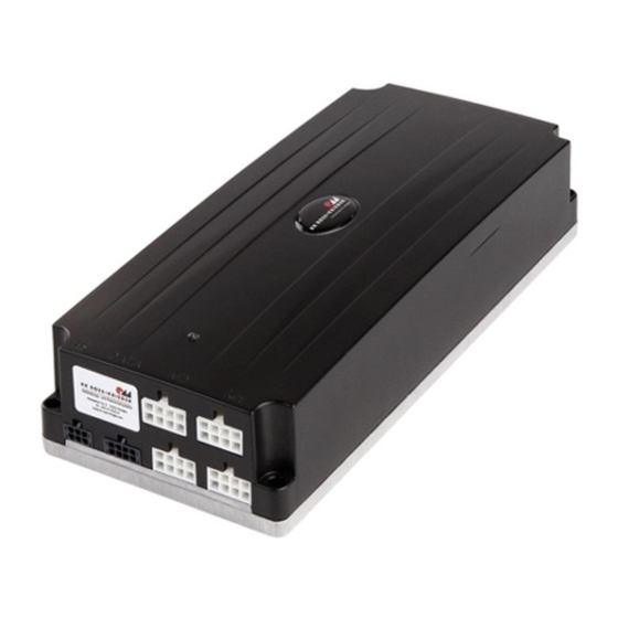
Abb. 4: Übersicht Steuerung MultiControl II quadro Vorderseite LED-Anzeige Ä Seite 109 Rückseite Typenschild Grundplatte Anschluss Kaltgerätezuleitung (Netzkabel) Ä Seite 109 Ä Seite 109 Konfigurationsschild FCC-/ MET-Schild Gehäuse Belegungsschild Ä Seite 27 Anschlussbelegung Steuerung RK MultiControl II duo/RK MultiControl II quadro 20.08.2021... -
Seite 23: Funktionsbeschreibung
Ä Seite 26 der RK Rose+Krieger GmbH ver- können Antriebe fahren werden. An die MultiControl II duo können zwei Antriebe und an die Multi- Control II quadro können bis zu vier Antriebe angeschlossen werden. Über einen Synchronisierungsbus (Sync-BUS) können bis zu acht Steuerungen miteinander verbunden und somit maximal 16 Antriebe (MultiControl II duo) bzw. -
Seite 24: Kaltgerätezuleitung
RS485-Schnittstelle der MultiControl II auf die digitalen Ein- und Ausgänge in beiden Richtungen. Weitere Informationen: Ä Kapitel 3.5.6 „Anschlussbelegung - I/O-Interface-Modul“ auf Seite 30 Ä Kapitel 5.4.6 „I/O-Interface-Modul anschließen“ auf Seite 44 Abb. 7: I/O-Interface-Modul Steuerung RK MultiControl II duo/RK MultiControl II quadro 20.08.2021... - Seite 25 Der Abschlusswiderstand (Abb. 9) wird dabei direkt an der DATA- Schnittstelle der ersten (Master-) und der letzten (Slave-) Steue- rung angeschlossen. Weitere Informationen: Abb. 9: Abschlusswiderstand Ä Kapitel 5.4.5 „Synchronisationsbus aufbauen“ auf Seite 43 (120 Ohm) 20.08.2021 Steuerung RK MultiControl II duo/RK MultiControl II quadro...
-
Seite 26: Antriebe
Sachschäden durch Verwendung eines nicht kompatiblen Antriebs! – Ausschließlich die in der Tabelle aufgeführten Antriebe von der RK Rose+Krieger GmbH ver- wenden. Kompatible Antriebe Folgende Antriebe von der RK Rose+Krieger GmbH können an die Steuerung angeschlossen werden: Anzeige/ Antrieb Nennlast [N] Auflösung... -
Seite 27: Anschlüsse
DATA-Schnittstelle Handschalterschnittstelle HS Der Antriebssteckplatz M1 muss immer belegt sein. An der DATA-Schnittstelle können Sensoren (z. B. Schaltleiste) oder ein Synchronisationsbus ange- schlossen werden. Abb. 11: MultiControl II quadro (Vor- derseite) 20.08.2021 Steuerung RK MultiControl II duo/RK MultiControl II quadro... -
Seite 28: Handschalterschnittstelle - Multicontrol Ii Duo/Quadro
Sensor 1 Schaltleiste grau 12 VDC 12 V ± 10 % rosa maximal 20 mA RS485 A Sync-BUS gelb Sensor 3 keine Funktion hinterlegt schwarz Ä Seite Externer Stoppeingang blau Sensor 4 Steuerung RK MultiControl II duo/RK MultiControl II quadro 20.08.2021... -
Seite 29: Antriebssteckplatz - Multicontrol Ii Duo/Quadro
Bei einem nicht betätigten Endschalter oben liegen +12 VDC an In Endlage ist der angeschlossene End- schalter-Kontakt offen Versorgung der Hall-Sensoren (Ausgang) Ansteuerung des Antriebs (Ausgang) Motor - 0 - 28,5 VDC 20.08.2021 Steuerung RK MultiControl II duo/RK MultiControl II quadro... -
Seite 30: Anschlussbelegung - I/O-Interface-Modul
Fehler quittieren: Setzt den aktiven Zustand eines Fehlers, sofern es möglich ist, zurück. RS485 A/B 9, 10 Control-BUS A/B Logik V+, 9 - 15 VDC, max. 40 mA Digital Input * Input-Spannungspegel ** Die Spannungsversorgung für digitale Eingänge Steuerung RK MultiControl II duo/RK MultiControl II quadro 20.08.2021... - Seite 31 Bei aktivem High-Pegel wird eine Initialisierungsfahrt eingeleitet. Nach eingestelltem Modus wird mit den AUF- und AB-Eingängen die Initialisierung durchgeführt. Memoryposition anfahren: Startet die Bewegung in Richtung der Memoryposition aus der Ä Seite 30. Tabelle 20.08.2021 Steuerung RK MultiControl II duo/RK MultiControl II quadro...
-
Seite 32: Klemme Funktion
21, 22 + Digital Output: 10 - 30 VDC, max. 4 A Digital Output * Output-Spannungspegel ** Die Spannungsversorgung für digitale Ausgänge an den Klemmen 23 + 24 betreiberseitig bereit- stellen Steuerung RK MultiControl II duo/RK MultiControl II quadro 20.08.2021... -
Seite 33: Transport Und Lagerung
Lagertemperatur: -25 - 80 °C Relative Luftfeuchtigkeit: 30 % - 75 %, Kondensation ver- meiden. Taupunktunterschreitung ist unzulässig. Umgebungsluftdruck: 700 hPa - 1600 hPa Abweichende Umgebungseinflüsse müssen durch die RK Rose+Krieger GmbH freigegeben werden. 20.08.2021 Steuerung RK MultiControl II duo/RK MultiControl II quadro... -
Seite 34: Montage
Es liegt keine lösemittelhaltige Atmosphäre vor. Alle notwendigen bauseitigen Anschlüsse stehen zur Verfügung. Raumtemperatur: +5 - +40 °C Relative Luftfeuchtigkeit: 30 - 75 % Luftdruck: 700 hPa - 1600 hPa Taupunktunterschreitung ist unzulässig. Steuerung RK MultiControl II duo/RK MultiControl II quadro 20.08.2021... -
Seite 35: Multicontrol Ii Montieren
– Schraubenkopfdurchmesser: 8 – Schraubendurchmesser: 5,5 mm – Durchstecktiefe: 20,5 mm – Anziehdrehmoment: 1,5 Nm 4 Schrauben in die Bohrlöcher (Abb. 18/1) einsetzen und abwechselnd über Kreuz festziehen. ð Die Steuerung ist montiert. 20.08.2021 Steuerung RK MultiControl II duo/RK MultiControl II quadro... -
Seite 36: Zubehör Anschließen
Antriebssteckplatz M2 stecken. Abb. 19: Antriebe anschließen ð Die Antriebe sind angeschlossen. Wenn das 3 m lange Verlängerungskabel für die Antriebe verwendet wird, die Verfahrgeschwindig- Ä Seite 94) reduzieren. keit (Parameter 11 Steuerung RK MultiControl II duo/RK MultiControl II quadro 20.08.2021... -
Seite 37: Antriebe An Multicontrol Ii Quadro Anschließen
Antriebssteckplätze M2 - M4 stecken. ð Die Antriebe sind angeschlossen. Wenn das 3 m lange Verlängerungskabel für die Antriebe verwendet wird, die Verfahrgeschwindig- Ä Seite 94) reduzieren. keit (Parameter 11 20.08.2021 Steuerung RK MultiControl II duo/RK MultiControl II quadro... -
Seite 38: Handschalter Anschließen
5 s gedrückt halten, um den Fehler zu quittieren. Alternativ den Netzstecker ziehen und 30 s warten. Danach wieder den Netzstecker ein- stecken. ð Der Handschalter mit 2 Funktionstasten ist betriebsbereit. Steuerung RK MultiControl II duo/RK MultiControl II quadro 20.08.2021... -
Seite 39: Betreiberseitige Schaltleiste Anschließen
Tabelle verbinden: Aderfarbe Funktion braun grau Sensor-Eingang 1 Abb. 22: BUS-Kabel anschließen (Steuerung) Ä Seite 79. Schaltleiste aktivieren Funktion „Schaltleiste“ aktivieren ð Die betreiberseitige Schaltleiste ist angeschlossen und aktiviert. 20.08.2021 Steuerung RK MultiControl II duo/RK MultiControl II quadro... - Seite 40 Der Nachlaufweg der Schaltleiste muss größer sein als der Anhalteweg des Antriebs/der Hub- säule. Der maximale Anhalteweg, z. B. der Variante Multilift II, beträgt Ä Tabelle auf Seite 41). 1,5 mm ( Steuerung RK MultiControl II duo/RK MultiControl II quadro 20.08.2021...
- Seite 41 Die zu verwendende Schaltleiste muss folgende Anforderungen erfüllen, damit die Schaltleiste von der Steuerung erkannt wird: Schaltwiderstand < 560 Ohm Schalt 1 k £ R £ 10 k Ohm Abschlusswiderstand Abschluss 20.08.2021 Steuerung RK MultiControl II duo/RK MultiControl II quadro...
-
Seite 42: Betreiberseitigen Stoppeingang Anschließen
ð Der betreiberseitige Stoppeingang ist angeschlossen und aktiviert. Wenn der Stoppeingang-Schalter während einer Verfahrbewegung betätigt wird, werden die Antriebe schnellstmöglich gestoppt. Wenn der Stoppeingang-Schalters deaktiviert wird Ä Seite 80, ist ein Verfahren der Antriebe wieder möglich. Steuerung RK MultiControl II duo/RK MultiControl II quadro 20.08.2021... -
Seite 43: Synchronisationsbus Aufbauen
Arbeitsschutzkleidung Sicherheitsschuhe Voraussetzung: Das Netzkabel ist von der Spannungsversorgung getrennt. 2 Steuerungen anschließen Abb. 25: Steuerungen anschließen BUS-Kabel (Abb. 25/1) in die Data-Schnittstellen der Steue- rungen (Abb. 25/A + B) stecken. 20.08.2021 Steuerung RK MultiControl II duo/RK MultiControl II quadro... -
Seite 44: I/O-Interface-Modul Anschließen
Control-BUS-Kabel an die MultiControl II angeschlossen werden. Das I/O-Interface-Modul nicht an Gleichspan- nungsnetze anschließen. Die an dem I/O-Interface-Modul angeschlossenen Leitungen dürfen nicht länger als 30 m sein und nicht außerhalb von Gebäuden verlegt werden. Steuerung RK MultiControl II duo/RK MultiControl II quadro 20.08.2021... -
Seite 45: Funktion
9 - 15 VDC, max. 40 mA braun Spannungsversorgung Logik GND Abb. 27: Control-BUS-Kabel anschließen (Klemmen) Control-BUS-Kabel (Abb. 28/1) in die Handschalterschnitt- stelle HS stecken. ð Das I/O-Interface-Modul ist angeschlossen. Abb. 28: Control-BUS-Kabel anschließen (Steuerung) 20.08.2021 Steuerung RK MultiControl II duo/RK MultiControl II quadro... -
Seite 46: Handschalter Mit 2 Funktionstasten Bedienen
– Alle Bedientätigkeiten nur durch qualifiziertes Personal ausführen lassen. 6.1 Übersicht Bedienoberfläche Taste [Ab] Taste [Auf] Durch Drücken der Tasten werden die an der Steuerung angeschlossenen Antriebe verfahren. Abb. 29: Bedienoberfläche Hand- schalter Steuerung RK MultiControl II duo/RK MultiControl II quadro 20.08.2021... -
Seite 47: Initialisierung Durchführen
Netzstecker einstecken und ca. 5 s warten. ð Die LED-Anzeige blinkt abwechselnd rot und grün. Tasten loslassen. Taste so lange gedrückt halten, bis alle Antriebe in die untere Endlage gefahren sind. 20.08.2021 Steuerung RK MultiControl II duo/RK MultiControl II quadro... - Seite 48 Initialisie- rungsfahrt an einer beliebigen Position beendet werden. Dazu die Taste für ca. 5 s gedrückt halten. Die neue Position der oberen Endlage der Antriebe ist eingestellt. Steuerung RK MultiControl II duo/RK MultiControl II quadro 20.08.2021...
-
Seite 49: Handschalter Mit 6 Funktionstasten Bedienen
Des Weiteren können die einzelnen Menü- Abb. 30/5 punkte innerhalb der Steuerung ausgewählt und Parameterwerte eingestellt werden. Durch Drücken der Taste [M] wird das Haupt- Abb. 30/6 menü Ä Seite 54 aufgerufen. Abb. 30: Bedienoberfläche 20.08.2021 Steuerung RK MultiControl II duo/RK MultiControl II quadro... -
Seite 50: Taste Funktion
Aktuelle Höhenanzeige mit eingestellter Maßeinheit (hier: 28,7 cm) Funktionstaste drücken. Die Memoryposition 1 des aktiven Benutzers wird angefahren. Funktionstaste drücken. Die Memoryposition 2 des aktiven Benutzers wird angefahren. Funktionstaste drücken. Die zu diesem Symbol gehörige Anzeige wird bestätigt. Steuerung RK MultiControl II duo/RK MultiControl II quadro 20.08.2021... -
Seite 51: Navigation
Jeder Druck auf die jeweilige Taste erhöht oder verringert die Ziffer. Durch Drücken der Taste ( ) oder der Taste ( ) kann inner- halb des Parameters eine Stelle nach rechts oder nach links gesprungen werden. 20.08.2021 Steuerung RK MultiControl II duo/RK MultiControl II quadro... - Seite 52 ) bestätigen. ð Der Menüpunkt „Steuerung“ (Abb. 32) ist ausgewählt. Abb. 32: Menü „Steuerung“ Das Menü „Steuerung“ ist mit einem Passwort geschützt. Basis-Passwort „13121“ (Abb. 33) einstellen. Abb. 33: Passwort einstellen Steuerung RK MultiControl II duo/RK MultiControl II quadro 20.08.2021...
- Seite 53 Stelle weiter nach rechts im Parameter zu springen. Abb. 36: Wert eingeben Nach Änderung der letzten Stelle bzw. Einheit des Parame- ters die Taste ) drücken. ð Die Basishöhe ist eingestellt. 20.08.2021 Steuerung RK MultiControl II duo/RK MultiControl II quadro...
-
Seite 54: Menüstruktur
1 Passwort auf Anfrage erhältlich. Nach Eingabe des Basis-Passworts werden diese Menüpunkte nicht angezeigt. 2 Menü nach Eingabe des Basis-Passworts 13121 oder des erweiterten Passworts erreichbar. 3 Nur in der Premium-Customized-Variante enthalten Nur in der Premiumvariante enthalten Steuerung RK MultiControl II duo/RK MultiControl II quadro 20.08.2021... -
Seite 55: Kurzmenü
Displays bzw. der Modus, in dem sich die Steuerung befindet, gewechselt werden. Folgende Ansichten können eingestellt werden: Memorypositionen (Standardansicht, Abb. 39) Absolute Positionierung (Abb. 41) Relative Positionierung (Abb. 44) Antriebsgruppenmanagement (Abb. 47) 20.08.2021 Steuerung RK MultiControl II duo/RK MultiControl II quadro... - Seite 56 7.4.1.1.2 Menü „Absolute Positionierung“ Diese Funktion aktiviert die absolute Positionie- rung. Damit wird ein präzises Anfahren einer definierten Position (z. B. 100 %) bezogen auf den kompletten Verstellbereich des Antriebs ermöglicht. Steuerung RK MultiControl II duo/RK MultiControl II quadro 20.08.2021...
- Seite 57 Abb. 41: Modus „Absolute Positionierung“ Absolute Zielposition (Abb. 42) einstellen. Abb. 42: Wert eingeben Absolute Zielposition anfahren Taste ) gedrückt halten. ð Bei Erreichen der Zielposition wird der Antrieb automa- tisch gestoppt. 20.08.2021 Steuerung RK MultiControl II duo/RK MultiControl II quadro...
- Seite 58 ð Das Display wechselt in den Modus „Relative Positionierung“ (Abb. 44). Abb. 43: Menü auswählen Relative Zielposition einstellen Taste ) drücken. Abb. 44: Modus „Relative Positionierung“ Relative Zielposition (Hub des Antriebs, Abb. 45) einstellen. Abb. 45: Wert eingeben Steuerung RK MultiControl II duo/RK MultiControl II quadro 20.08.2021...
- Seite 59 Menü über „Handschalter“ ® „Premiumfunktionen“ ® „Einstellungen der Funktionstasten“ ® „Antriebsgruppenmanagement“ (Abb. 46) auswählen. Abb. 46: Menü auswählen ð Das Display wechselt in den Modus „Antriebsgruppenmanagement“ (Abb. 47). Abb. 47: Modus „Antriebsgruppenmanagement“ 20.08.2021 Steuerung RK MultiControl II duo/RK MultiControl II quadro...
-
Seite 60: Menü „Tastensperre
ð Die Tastensperre kann nun jederzeit durch 5 s anhal- tendes Drücken der Taste aktiviert werden. Abb. 49: Tastensperre einstellen Tastensperre (zeitgesteuert) ein- stellen Menüpunkt „Zeitgesteuert“ (Abb. 50) auswählen. Abb. 50: Tastensperre einstellen Steuerung RK MultiControl II duo/RK MultiControl II quadro 20.08.2021... - Seite 61 Handschalter wird gesperrt (Abb. 53). Handschalter entsperren Um den Handschalter zu entsperren, Taste Abb. 53: Handschalter sperren gedrückt halten. Die Zeit wird rückwärtslaufend im Display ange- zeigt und der Handschalter wird entsperrt. 20.08.2021 Steuerung RK MultiControl II duo/RK MultiControl II quadro...
-
Seite 62: Menü „Kontrast
Abb. 55: Kontrast einstellen 7.4.3 Menü „Helligkeit“ Voraussetzung: Ä Seite 54. Das Hauptmenü des Handschalters wird angezeigt Menü auswählen Menü über „Handschalter“ ® „Helligkeit“ (Abb. 56) aus- wählen. Abb. 56: Menü auswählen Steuerung RK MultiControl II duo/RK MultiControl II quadro 20.08.2021... -
Seite 63: Menü „Beleuchtungszeit
0 s; 10 s; 20 s; 30 s; Bei 0 s wird das Display nicht beleuchtet. Bei ∞ s Dauerbeleuchtung. Neue Beleuchtungszeit (Abb. 59) einstellen. Abb. 59: Beleuchtungszeit einstellen ð Die Beleuchtungszeit ist eingestellt. 20.08.2021 Steuerung RK MultiControl II duo/RK MultiControl II quadro... -
Seite 64: Menü „Sprache
Mit dem Basis-Passwort können nicht alle Menü- punkte innerhalb des Menüs „Steuerung“ erreicht werden. Dazu wird das erweiterte Passwort benö- tigt. Das erweiterte Passwort ist auf Anfrage bei der RK Rose+Krieger GmbH erhältlich. Steuerung RK MultiControl II duo/RK MultiControl II quadro 20.08.2021... -
Seite 65: Menü „Inbetriebnahme
Meldung „Initialisierung starten?“ auf dem Display entsprechende Fehlermeldung Ä Seite 103 Aktivierung des Anbtriebsgruppenmanagements Ä Seite 67 Damit die Antriebe verfahren werden können, muss die Initialisierungsfahrt vollständig abge- schlossen sein. 20.08.2021 Steuerung RK MultiControl II duo/RK MultiControl II quadro... -
Seite 66: Initialisierungsfahrt Durchführen
Initialisie- rungsfahrt an einer beliebigen Position beendet werden. Dazu die Taste für ca. 5 s gedrückt halten. Die neue Position der oberen Endlage der Antriebe ist eingestellt. Steuerung RK MultiControl II duo/RK MultiControl II quadro 20.08.2021... -
Seite 67: Konfigurieren/Deaktivieren
M1 + M3 M1 + M2 + M3 M1 + M2 M1 + M3 + M4 M3 + M4 M1 + M2 + M3 + M4 M1 + M2 M3 + M4 20.08.2021 Steuerung RK MultiControl II duo/RK MultiControl II quadro... -
Seite 68: Antriebsgruppenmanagement Bei Erstinbetriebnahme Aktivieren
Abb. 66: Initialisierung starten Antriebsgruppenmanagement aus- wählen Menü über „Steuerung“ ® „Inbetriebnahme“ ® „Antriebsgruppenmanagement konfigurieren“ auswählen. ð Die Meldung „Festlegung des Antriebstyp für Antriebsgruppe 2“ (Abb. 68) wird angezeigt. Abb. 67: Antriebsgruppenmanage- ment konfigurieren Steuerung RK MultiControl II duo/RK MultiControl II quadro 20.08.2021... - Seite 69 1 durchführen Initialisierungsfahrt für die erste Antriebsgruppe ( ) durch- Ä Seite 65. führen Abb. 69: Initialisierungsfahrt durch- führen Antriebsgruppe 2 auswählen Zweite Antriebsgruppe ( ) auswählen. Abb. 70: Antriebsgruppe 2 auswählen 20.08.2021 Steuerung RK MultiControl II duo/RK MultiControl II quadro...
- Seite 70 Die Antriebe sind an der MultiControl II quadro angeschlossen Ä Seite 37. Werkseinstellung laden Steuerung auf Werkseinstellung zurücksetzen Ä Seite 96. Abb. 72: Menü „Werkseinstellungen laden“ Sprache einstellen Ä Seite 64. Sprache einstellen Abb. 73: Sprache einstellen Steuerung RK MultiControl II duo/RK MultiControl II quadro 20.08.2021...
- Seite 71 Abb. 75: Antriebsgruppenmanage- ment konfigurieren Antriebsgruppe 2 einstellen Die erste Antriebsgruppe ist werkseitig einge- stellt. Ä Kom- Antriebstyp für die zweite Antriebsgruppe einstellen patible Antriebe auf Seite 26. Abb. 76: Antriebsgruppe 2 einstellen 20.08.2021 Steuerung RK MultiControl II duo/RK MultiControl II quadro...
- Seite 72 Nenngeschwindigkeit der angeschlossenen Antriebe bewegt und stoppt bei Erreichen der Endschalter separat. Nach Beendigung der Initialisierungsfahrten wech- Abb. 79: Initialisierungsfahrt durch- selt das Display in den Modus "Antriebsmanage- führen ment". Steuerung RK MultiControl II duo/RK MultiControl II quadro 20.08.2021...
- Seite 73 ð Die ausgewählte Antriebsgruppe ist aktiviert und wird invers ( oder ) dargestellt. Abb. 81: Antriebsgruppenmanage- ment aktiviert Tasten drücken, um die ausgewählte Antriebsgruppe (hier: ) zu verfahren. Abb. 82: Antriebsgruppe verfahren 20.08.2021 Steuerung RK MultiControl II duo/RK MultiControl II quadro...
- Seite 74 ð Beide Antriebsgruppen bewegen sich in der jeweils ein- gestellten Geschwindigkeit. Wenn während des synchronen Verfahrens eine Antriebsgruppe an einer Endlage stehenbleibt, stoppt die andere Antriebsgruppe ebenfalls. Abb. 85: Antriebsgruppen verfahren Steuerung RK MultiControl II duo/RK MultiControl II quadro 20.08.2021...
-
Seite 75: Menü „Hubanzeige
Hubhöhe und Einheit einstellen Neue Hubhöhe (Abb. 87) und Einheit (cm, mm, Inch oder %) einstellen. ð Eine neue Hubhöhe und Einheit für die Hubanzeige ist eingestellt. Abb. 87: Wert eingeben 20.08.2021 Steuerung RK MultiControl II duo/RK MultiControl II quadro... -
Seite 76: Menü „Basishöhe Ändern
Abb. 89: Wert eingeben 7.5.3 Menü „Hubbegrenzung“ 7.5.3.1 Menü „Hubbegrenzung oben“ Eine Begrenzung des Hubs nach oben kann ent- weder bei der Initialisierungsfahrt oder nachträglich über das Menü „Hubbegrenzung oben“ eingestellt werden. Steuerung RK MultiControl II duo/RK MultiControl II quadro 20.08.2021... -
Seite 77: Menü Hubbegrenzung Unten
Endlage wird übernommen. Abb. 92: Hubbegrenzung deaktivieren 7.5.3.2 Menü Hubbegrenzung unten Eine Begrenzung des Hubs nach unten kann ent- weder bei der Initialisierungsfahrt oder nachträglich über das Menü „Hubbegrenzung unten“ eingestellt werden. 20.08.2021 Steuerung RK MultiControl II duo/RK MultiControl II quadro... - Seite 78 ð Die aktuelle Position der Antriebe wird als untere End- lage übernommen. Abb. 94: Hubbegrenzung aktivieren Hubbegrenzung deaktivieren „Hubbegrenzung unten deaktivieren“ (Abb. 95) auswählen. ð Die bei der Initialisierungsfahrt ermittelte bzw. eingestellte untere Endlage wird übernommen. Abb. 95: Hubbegrenzung deaktivieren Steuerung RK MultiControl II duo/RK MultiControl II quadro 20.08.2021...
-
Seite 79: Menü „Stoppfunktionen
Schaltleiste aktivieren „Schaltleiste aktivieren“ (Abb. 97) auswählen. ð Die Schaltleiste ist aktiviert. Abb. 97: Schaltleiste aktivieren Schaltleiste deaktivieren „Schaltleiste deaktivieren“ (Abb. 98) auswählen. ð Die Schaltleiste ist deaktiviert. Abb. 98: Schaltleiste deaktivieren 20.08.2021 Steuerung RK MultiControl II duo/RK MultiControl II quadro... -
Seite 80: Menü „Externer Stoppeingang
Menü über „Steuerung“ ® „Stoppfunktionen“ ® „Externer Stoppeingang“ (Abb. 99) auswählen. Abb. 99: Menü auswählen Stoppeingang aktivieren „Stoppeingang aktivieren“ (Abb. 100) auswählen. ð Der Stoppeingang-Schalter ist aktiviert. Abb. 100: Stoppeingang aktivieren Steuerung RK MultiControl II duo/RK MultiControl II quadro 20.08.2021... -
Seite 81: Menü „Kollisionserkennung (Spp)
Die Kollisionserkennung kann Hindernisse erst nach einer Beschleunigungsphase (in der Standardeinstellung nach ca. 1 s) erkennen. Nach Erkennen eines Hindernisses wird die Bewegung gestoppt und das Verfahren in die letzte Verfahrrichtung blockiert. 20.08.2021 Steuerung RK MultiControl II duo/RK MultiControl II quadro... -
Seite 82: Menü "Kollisionserkennung (Spp)" Auswählen
Menü über „Steuerung“ ® „Stoppfunktionen“ ® „Kollisionserkennung (SPP)“ (Abb. 102) auswählen. Abb. 102: Menü auswählen Verfahrrichtung auswählen Verfahrrichtung „Ausfahren“ oder „Einfahren“ auswählen (hier: „Ausfahren“ , Abb. 103). Abb. 103: Verfahrrichtung auswählen Steuerung RK MultiControl II duo/RK MultiControl II quadro 20.08.2021... - Seite 83 Alternativ über Handlungsschritt 3 für jede Verfahrrichtung eine Erkennungs- schwelle von 0 mA einstellen. Abb. 106: Kollisionserkennung deakti- vieren Hinweise zur Erkennungsschwelle Die erzielbare Empfindlichkeit von der Kollisionserkennung (SPP) hängt vom gesamten System ab. 20.08.2021 Steuerung RK MultiControl II duo/RK MultiControl II quadro...
-
Seite 84: Menü „Sync-Bus Einstellungen
7.5.5.1 Menü „Starte Suche nach Steuerungen“ Diese Funktion sucht nach den angeschlossenen Ä Seite 43 und aktiviert den Busver- Steuerungen band. Diese Funktion kann bei einem aktivierten Antriebsgruppenmanagement nicht aktiviert werden. Steuerung RK MultiControl II duo/RK MultiControl II quadro 20.08.2021... - Seite 85 Nachdem der Synchronisationsbus ange- schlossen, aktiviert und initialisiert wurde, kann der Handschalter mit 2 Tasten Ä Seite 46 ebenfalls zum Bedienen des Busverbands verwendet werden. Ä Seite 38. Dazu die Handschalter auswechseln 20.08.2021 Steuerung RK MultiControl II duo/RK MultiControl II quadro...
-
Seite 86: Menü „Busverband Deaktivieren
7.5.6 Menü „I/O Interface Memorypositionen“ Mit Hilfe dieser Funktion können sieben I/O-Inter- face-Memorypositionen belegt und angefahren werden. Zum Speichern muss zuerst die jeweilige Memory- Ä Seite position mit Hilfe des I/O-Interface-Moduls 24 angefahren werden. Steuerung RK MultiControl II duo/RK MultiControl II quadro 20.08.2021... -
Seite 87: Memorypositionen Speichern
Ä Seite 87. Das Hauptmenü des Handschalters wird angezeigt Ä Seite 54. Menü auswählen Menü über „Steuerung“ ® „ I/O Interface Memorypositionen“ ® „Memorypositionen anfahren“ (Abb. 112) auswählen. Abb. 112: Menü auswählen 20.08.2021 Steuerung RK MultiControl II duo/RK MultiControl II quadro... -
Seite 88: Menü „Service
Abb. 114: Menü auswählen Fehlerhistorie Beschreibung Betriebslaufzeit der Steuerung Hier: 32 Tage, 1 Stunde, 32 Minuten, 57 Sekunden Art des Fehlers Ä Seite 103 Hier: Fehlercode „E38“ Abb. 115: Menü „Fehlerhistorie anzeigen“ Steuerung RK MultiControl II duo/RK MultiControl II quadro 20.08.2021... -
Seite 89: Menü „Ansicht
Passwort eingestellt worden ist Das erweiterte Passwort ist auf Anfrage bei der RK Rose+Krieger GmbH erhältlich. Menü „Ansicht“ auswählen Die Funktion dient der Überprüfung des Systems auf mögliche Überlasten oder Verteilung der Lasten. 20.08.2021 Steuerung RK MultiControl II duo/RK MultiControl II quadro... -
Seite 90: Menü „Service Drive
Das erweiterte Passwort ist auf Anfrage bei der RK Rose+Krieger GmbH erhältlich. Menü „SERVICE DRIVE“ aus- wählen Die Funktion ermöglicht ein Verfahren von ein- zelnen oder mehreren Antrieben auch im Fehlerfall zwecks Fehlersuche. Steuerung RK MultiControl II duo/RK MultiControl II quadro 20.08.2021... -
Seite 91: Menü „Anzeige Optionsregister
Ä Seite 65. Initialisierungsfahrt durchführen Initialisierungsfahrt durchführen 7.5.7.4 Menü „Anzeige Optionsregister“ Diese Funktion steht nur in der Ausführung Pre- mium customized zur Verfügung und dient der Anzeige aktivierter Optionen von Steuerungen mit Sonderfunktionen. 20.08.2021 Steuerung RK MultiControl II duo/RK MultiControl II quadro... -
Seite 92: Menü „Parameter
Das Hauptmenü des Handschalters wird angezeigt Menü auswählen Menü über „Steuerung“ ® „Parameter“ ® „Parametersatz übertragen“ (Abb. 122) auswählen. ð Das Menü „Parameter übertragen“ (Abb. 123) wird ange- zeigt. Abb. 122: Menü auswählen Steuerung RK MultiControl II duo/RK MultiControl II quadro 20.08.2021... -
Seite 93: Menü „Parameter Ändern
Das erweiterte Passwort ist auf Anfrage bei der RK Rose+Krieger GmbH erhältlich. Menü „Parameter ändern“ aus- wählen Die Funktion ermöglicht das direkte Ändern der Parameter, um die Einstellungen einer Steuerung anzupassen. 20.08.2021 Steuerung RK MultiControl II duo/RK MultiControl II quadro... - Seite 94 9999 Zustand: 0 - % Einheit, Eingabe der Einheit für die Anzeige: 0 - %; 1 - cm; 2 - mm; 3 - Inch Sicherheitsschaltleiste: 0 - deaktivieren; 1 - aktivieren Steuerung RK MultiControl II duo/RK MultiControl II quadro 20.08.2021...
- Seite 95 Freifahren, 3 - automatisches Freifahren in Gegenrichtung Initialisierungsmodus. Werkseinstellung: 0 - Verfahren unten und oben; 1 - nur unten; 2 - nur oben Siehe Antriebstyp (z. B. 11 - Multilift II) Konf. 20.08.2021 Steuerung RK MultiControl II duo/RK MultiControl II quadro...
-
Seite 96: Menü „Werkseinstellungen Laden
Festlegung der Hallsensorverhältnisse von Gruppe 1 zu Gruppe 2. 10000 2000 60000 Werkseitig ist der Parameter auf 10000 (Faktor 1,0) eingestellt. 7.5.9 Menü „Werkseinstellungen laden“ Die Funktion ermöglicht das Zurücksetzen aller Einstellungen auf Werkseinstellungen. Steuerung RK MultiControl II duo/RK MultiControl II quadro 20.08.2021... -
Seite 97: Menü „Logout
Menü „Logout“ Die Funktion ermöglicht die Aufhebung einer vor- herigen Passworteingabe. Dadurch können Funkti- onen gesperrt oder ein anderes Passworts einge- geben werden. Die Passworteingabe wird automatisch nach 30 Minuten aufgehoben. 20.08.2021 Steuerung RK MultiControl II duo/RK MultiControl II quadro... -
Seite 98: Menü „Info
Über diese Funktion können Informationen, z. B. über die angeschlossenen Hardwarekomponenten, angezeigt werden. Voraussetzung: Das Hauptmenü des Handschalters wird angezeigt Ä Seite 54. Menü „Info“ auswählen Menü „Info“ auswählen. Abb. 130: Menu „Info“ auswählen Steuerung RK MultiControl II duo/RK MultiControl II quadro 20.08.2021... -
Seite 99: Menü „Memorypositionen Speichern
Voraussetzungen: Die zu speichernde Position des Antriebs ist angefahren. Ä Seite 55. Das Kurzmenü des Handschalters wird angezeigt Menü auswählen Menü „Memorypositionen speichern“ ( ) auswählen. Abb. 133: Menü auswählen 20.08.2021 Steuerung RK MultiControl II duo/RK MultiControl II quadro... -
Seite 100: Menü „Benutzerauswahl
Abb. 135: Memoryposition anfahren 7.8 Menü „Benutzerauswahl“ Die Funktion ermöglicht das Auswählen des Benutzers. Der Benutzer 1 ( ) ist werkseitig als aktiver Benutzer eingestellt und wird oben rechts im Dis- play angezeigt. Steuerung RK MultiControl II duo/RK MultiControl II quadro 20.08.2021... - Seite 101 Abb. 136: Menü auswählen Benutzer auswählen Neuen Benutzer (1 - 3) auswählen. ð Der neue Benutzer ist aktiviert. Der ausgewählte Benutzer bleibt auch nach Aus- schalten der Steuerung erhalten. Abb. 137: Benutzer auswählen 20.08.2021 Steuerung RK MultiControl II duo/RK MultiControl II quadro...
-
Seite 102: Wartung Und Störungsbehebung
Wartungsintervalle entsprechend den tatsächlichen Verschleißerscheinungen verkürzen. Bei Fragen zu Wartungsarbeiten und -intervallen die RK Rose+Krieger GmbH kontaktieren Ä Seite 7. Betreiberseitige Komponenten gemäß den Angaben der jeweiligen Hersteller regelmäßig warten. Steuerung RK MultiControl II duo/RK MultiControl II quadro 20.08.2021... -
Seite 103: Störungsbehebung
Tabelle Fehlermeldungen Code Beschreibung Störungsbehebung Fehler Motorstrom Antrieb 1 zu „E2“ hoch Bei häufigem Auftreten des Fehlers System auf mechanische Überlast prüfen. Fehler Motorstrom Antrieb 2 zu „E3“ hoch 20.08.2021 Steuerung RK MultiControl II duo/RK MultiControl II quadro... -
Seite 104: Code Beschreibung
Steuerungen prüfen. Fehler Endschalterkonfiguration Zur Konfiguration der Steuerung passenden Antrieb ver- „E41“ (falscher Antrieb) wenden. Antrieb ist möglicherweise defekt. Antrieb auf mechanische „E42“ Differenz Master zu Slave zu groß Belastung prüfen. Steuerung RK MultiControl II duo/RK MultiControl II quadro 20.08.2021... -
Seite 105: Nach Der Wartung Und Störungsbehebung
Alle zuvor gelösten Schraubenverbindungen auf festen Sitz überprüfen. Sicherstellen, dass alle verwendeten Werkzeuge, Materialien und sonstige Ausrüstungen aus dem Arbeitsbereich entfernt wurden. Arbeitsbereich säubern und eventuell ausgetretene Stoffe wie z. B. Flüssigkeiten, Verarbeitungsmaterial oder Ähnliches entfernen. 20.08.2021 Steuerung RK MultiControl II duo/RK MultiControl II quadro... -
Seite 106: Demontage Und Entsorgung
Raum der EU-Richtlinie 2012/19/EU oder den jeweiligen nationalen Gesetzgebungen. Sofern keine Rücknahme- oder Entsorgungsvereinbarung getroffen wurde, zerlegte Bestandteile der Wiederverwertung zuführen: Metalle verschrotten. Kunststoffelemente zum Recycling geben. Übrige Komponenten nach Materialbeschaffenheit sortiert ent- sorgen. Steuerung RK MultiControl II duo/RK MultiControl II quadro 20.08.2021... - Seite 107 örtlichen Kommunalbehörde oder speziellen Entsorgungsfachbetrieben ein- holen. Elektronikkomponenten Elektronikkomponenten und Elektroschrott gelten als Sondermüll und dürfen nicht im Hausmüll entsorgt werden. Elektronikkomponenten und Elektroschrott ausschließlich durch dafür zugelassene Entsorgungsfachbetriebe entsorgen lassen. 20.08.2021 Steuerung RK MultiControl II duo/RK MultiControl II quadro...
-
Seite 108: Technische Daten
IP20 +5 °C - +40 °C Raumtemperatur 700 hPa - 1600 hPa Luftdruck 30 % - 75 % Relative Luftfeuchtigkeit * Standby Aufnahmeleistung ist in Kombination mit Multilift I/Multilift synchron höher Steuerung RK MultiControl II duo/RK MultiControl II quadro 20.08.2021... -
Seite 109: Typenschild
Arbeitsplatz geprüft und zertifiziert wurden. Die FCC-Kennzeichnung (Abb. 140/2) ist notwendig für die Zulas- sung jeglicher Kommunikationsgeräte für den US-amerikanischen Abb. 140: FCC-/MET-Schild Markt. Die FCC-Kennzeichnung bestätigt die elektromagnetische Verträglichkeit von elektronischen Produkten. 20.08.2021 Steuerung RK MultiControl II duo/RK MultiControl II quadro... -
Seite 110: Index
Belegung Antriebe ..... 67 MultiControl II duo ..... 27 deaktivieren . - Seite 111 Initialisierungsfahrt starten ....65 Menü Memorypositionen speichern ... 99 20.08.2021 Steuerung RK MultiControl II duo/RK MultiControl II quadro...
- Seite 112 ......51 Antriebe anschließen (MultiControl II duo) . . . 36 Tabelle ......94 Antriebe anschließen (MultiControl II quadro) 37...
- Seite 113 Verwendung ..14 MultiControl II duo ..... 22 Fehlgebrauch ......14 MultiControl II quadro .