Inhaltsverzeichnis
Werbung
Verfügbare Sprachen
Verfügbare Sprachen
Quicklinks
Gesamtbedienungsanleitung
Für
ADH75M*8192/32768 EPN HW20H7/N +FS
Material Nr.
ADH75M-00002
Generiert am
12.07.2023
Enthält Originalbedienungsanleitung
Dokumentationsabschnitte
EX-Benutzerhandbuch de
AD_582/AD_75 EX-Handbuch 3G/3D ohne SSI
Montageanleitung de
CD_75/88/100/115 Sicherheitshandbuch
Betriebsanleitung
de
CD_75/88/100/115 EPN+FS
Zertifikat
de/en Baumusterprüfbescheinigung 75/88 + FS
Zertifikat
de/en UK Type-Examination Certificate 75/88 FS
Technische Info
de
Rev-Liste 75/88 + FS, 01/205/5518
Technische Info
de
Rev-Liste 75/88 + FS, 01/205U/5518
Technische Info
de/en Info, SIMATIC S7 - CDx75 PN/PS Beschr.
Technische Info
de/en Info, S7-1500/S7-300/S7-400; CDx75 PN/PS
Konformitätserklärung de
AD_75M SIL3 alle Schnittstellen ohne SSI
Technische Daten
Seite 1/1
TR-ECE-BA-D-0099-13.pdf
TR-ECE-BA-D-0107-19.pdf
TR-ECE-BA-D-0095-24.pdf
TR-ECE-TI-DGB-0297-01.pdf
TR-ECE-TI-DGB-0395-00.pdf
TR-ECE-TI-D-0305-03.pdf
TR-ECE-TI-D-0396-00.pdf
TR-ECE-TI-DGB-0233-03.pdf
TR-ECE-TI-DGB-0292-02.pdf
TR-ECE-KE-D-0343-03.pdf
Änderungen vorbehalten.
TR-Electronic GmbH
Eglishalde 6
78647 Trossingen
Tel. +49 (0) 7425 228-0
info@tr-electronic.de
www.tr-electronic.de
Werbung
Inhaltsverzeichnis

Verwandte Anleitungen für TR-Electronic AD 582 Serie


Inhaltszusammenfassung für TR-Electronic AD 582 Serie
- Seite 1 Info, SIMATIC S7 - CDx75 PN/PS Beschr. TR-ECE-TI-DGB-0233-03.pdf Technische Info de/en Info, S7-1500/S7-300/S7-400; CDx75 PN/PS TR-ECE-TI-DGB-0292-02.pdf Konformitätserklärung de AD_75M SIL3 alle Schnittstellen ohne SSI TR-ECE-KE-D-0343-03.pdf Technische Daten Änderungen vorbehalten. TR-Electronic GmbH Eglishalde 6 78647 Trossingen Tel. +49 (0) 7425 228-0 Seite 1/1 info@tr-electronic.de www.tr-electronic.de...
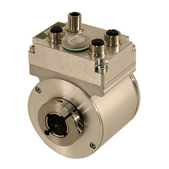
- Seite 2 Original Mess-Systeme AD*582* / AD*75* mit Funktionaler Sicherheit, für den Einsatz in explosionsgefährdeten Bereichen ADV582 ADV75 Abbildungen: exemplarische Beispiele II 3G II 3D Date of manufacture: DD.MM.YYYY _Grundlegende Sicherheitshinweise _Verwendungszweck _Produktbeschreibung _Explosionsschutz Kenndaten _Download: Technische Unterlagen Benutzerhandbuch...
- Seite 3 Courier-Schrift zeigt Text an, der auf dem Display bzw. Bildschirm sichtbar ist und Menüauswahlen von Software. < > weist auf Tasten der Tastatur Ihres Computers hin (wie etwa <RETURN>). TR-Electronic GmbH 2012, All Rights Reserved Printed in the Federal Republic of Germany Seite 2 von 23 TR-ECE-BA-D-0099 v13...
-
Seite 4: Inhaltsverzeichnis
6.1 AD_75 ............................. 19 6.2 AD_582 ........................... 21 7 Download ............................23 7.1 Technische Unterlagen zur Artikel-Nummer ................23 TR-Electronic GmbH 2012, All Rights Reserved Printed in the Federal Republic of Germany 05.12.2022 TR-ECE-BA-D-0099 v13 Seite 3 von 23... - Seite 5 Gerätekennzeichnung, Bestimmungsgemäße Verwendung, Besondere Bedingungen, Potenzialausgleich Änderung in Kap. „Potenzialausgleichsleitung – Anschluss“ 05.12.2022 - Querschnitt muss mindestens 4 mm sein. TR-Electronic GmbH 2012, All Rights Reserved Printed in the Federal Republic of Germany Seite 4 von 23 TR-ECE-BA-D-0099 v13 05.12.2022...
-
Seite 6: Allgemeines
Bestandteil einer Anlage. Es gelten somit zusammen die in den Sicherheitshandbüchern unter Kapitel „Mitgeltende Dokumente“ aufgeführten Dokumentationen: AD*582: https://www.tr-electronic.de/f/TR-ECE-BA-D-0142 AD*75: https://www.tr-electronic.de/f/TR-ECE-BA-D-0107 TR-Electronic GmbH 2012, All Rights Reserved Printed in the Federal Republic of Germany 05.12.2022 TR-ECE-BA-D-0099 v13 Seite 5 von 23... -
Seite 7: Angewandte Richtlinien Und Normen
Geräteschutz durch Zündschutzart "n" Explosionsfähige Atmosphäre: Geräte - EN 60079-31 Staubexplosionsschutz durch Gehäuse "t" DIN EN 60529 Schutzarten durch Gehäuse (IP-Code) TR-Electronic GmbH 2012, All Rights Reserved Printed in the Federal Republic of Germany Seite 6 von 23 TR-ECE-BA-D-0099 v13 05.12.2022... -
Seite 8: Verwendete Abkürzungen / Begriffe
Rotativ-Mess-System. Der Aufbau, sowie das Zusammenwirken der einzelnen Komponenten und des Gehäuses hinsichtlich ihrer Einsatzfähigkeit in explosionsgefährdeten Bereichen, werden von der Firma TR-Electronic GmbH geprüft und durch die Kennzeichnung mit dem ATEX-Typenschild bestätigt. Kennzeichnung für Geräte bis ca. 2020 Kennzeichnung für Geräte ab ca. -
Seite 9: Grundlegende Sicherheitshinweise
Bei Defekten darf das Betriebsmittel nicht betrieben werden, es darf grundsätzlich nicht geöffnet werden und Staubablagerungen > 5 mm müssen beseitigt werden. TR-Electronic GmbH 2012, All Rights Reserved Printed in the Federal Republic of Germany Seite 8 von 23 TR-ECE-BA-D-0099 v13 05.12.2022... -
Seite 10: Bestimmungsgemäße Verwendung
Verbots- bzw. Hinweisschilder, • das Beachten beigefügter Dokumente, • das Betreiben des Betriebsmittels innerhalb der in den technischen Daten angegebenen Grenzwerte TR-Electronic GmbH 2012, All Rights Reserved Printed in the Federal Republic of Germany 05.12.2022 TR-ECE-BA-D-0099 v13 Seite 9 von 23... -
Seite 11: Bestimmungswidrige Verwendung
(Gerätekategorien) nicht auf dem Typenschild aufgeführt sind zu medizinischen Zwecken die Inbetriebnahme des Betriebsmittels, wenn die Typenschilder nicht mehr lesbar sind oder gänzlich fehlen. TR-Electronic GmbH 2012, All Rights Reserved Printed in the Federal Republic of Germany Seite 10 von 23 TR-ECE-BA-D-0099 v13... -
Seite 12: Gewährleistung Und Haftung
Dokumentationen ausdrücklich beschriebenen, vornehmen. • Reparaturen dürfen nur vom Hersteller, oder einer vom Hersteller autorisierten Stelle bzw. Person vorgenommen werden. TR-Electronic GmbH 2012, All Rights Reserved Printed in the Federal Republic of Germany 05.12.2022 TR-ECE-BA-D-0099 v13... -
Seite 13: Personalauswahl Und -Qualifikation; Grundsätzliche Pflichten
Die Funktionssicherheit des Betriebsmittels sowie die funktionsgerechte Anordnung des Betriebsmittels innerhalb der Anlage sind vor der Inbetriebnahme zu überprüfen. Die Verwendung darf nur im unbeschädigten und sauberen Zustand erfolgen. TR-Electronic GmbH 2012, All Rights Reserved Printed in the Federal Republic of Germany Seite 12 von 23 TR-ECE-BA-D-0099 v13 05.12.2022... -
Seite 14: Montage, Installation Und Demontage
Kapitel „Potenzialausgleichsleitung – Anschluss“ auf Seite 18. Verdrahtungsarbeiten, Öffnen und Schließen von elektrischen Verbindungen dürfen nur im spannungslosen Zustand durchgeführt werden. TR-Electronic GmbH 2012, All Rights Reserved Printed in the Federal Republic of Germany 05.12.2022 TR-ECE-BA-D-0099 v13... -
Seite 15: Prüfung, Wartung Und Instandhaltung
Überprüfung der Anschluss-Stecker auf festen Sitz ➢ Bei Schäden ist das Betriebsmittel umgehend außer Betrieb zu nehmen und vom Hersteller instand setzen zu lassen! TR-Electronic GmbH 2012, All Rights Reserved Printed in the Federal Republic of Germany Seite 14 von 23 TR-ECE-BA-D-0099 v13 05.12.2022... -
Seite 16: Besondere Bedingungen Für Die Sichere Verwendung, Kennzeichnung „X
● Der Anschluss des freien Zuleitungsendes muss entweder außerhalb des explosionsgefährdeten Bereiches bzw. einem für entsprechende Gerätekategorie zugelassenem Betriebsmittel erfolgen. TR-Electronic GmbH 2012, All Rights Reserved Printed in the Federal Republic of Germany 05.12.2022 TR-ECE-BA-D-0099 v13 Seite 15 von 23... -
Seite 17: Explosionsschutz Kenndaten
Geräteschutzniveau ..........Gc: Zone 2 ausreichende Sicherheit bei normalem Betrieb Besondere Bedingungen ........X: siehe Kapitel 2.11 auf Seite 15 TR-Electronic GmbH 2012, All Rights Reserved Printed in the Federal Republic of Germany Seite 16 von 23 TR-ECE-BA-D-0099 v13 05.12.2022... -
Seite 18: Ex-Kennzeichnung, Staub
Typenschild Besondere Bedingungen ........X: siehe Kapitel 2.11 auf Seite 15 Hinweise zur sicheren Verwendung beachten, siehe Kapitel 2.11 auf Seite 16 TR-Electronic GmbH 2012, All Rights Reserved Printed in the Federal Republic of Germany 05.12.2022 TR-ECE-BA-D-0099 v13... -
Seite 19: Gehäuse - Beschaffenheit
Die Lage des Anschlusses ist abhängig von der Baureihe und wird daher in den kundenspezifischen Maßzeichnungen angegeben. Siehe hierzu Kapitel Download auf Seite 23. TR-Electronic GmbH 2012, All Rights Reserved Printed in the Federal Republic of Germany Seite 18 von 23 TR-ECE-BA-D-0099 v13 05.12.2022... -
Seite 20: Eu-Konformitätserklärungen
6 EU-Konformitätserklärungen 6.1 AD_75 TR-Electronic GmbH 2012, All Rights Reserved Printed in the Federal Republic of Germany 05.12.2022 TR-ECE-BA-D-0099 v13 Seite 19 von 23... - Seite 21 EU-Konformitätserklärungen TR-Electronic GmbH 2012, All Rights Reserved Printed in the Federal Republic of Germany Seite 20 von 23 TR-ECE-BA-D-0099 v13 05.12.2022...
-
Seite 22: Ad_582
6.2 AD_582 TR-Electronic GmbH 2012, All Rights Reserved Printed in the Federal Republic of Germany 05.12.2022 TR-ECE-BA-D-0099 v13 Seite 21 von 23... - Seite 23 EU-Konformitätserklärungen TR-Electronic GmbH 2012, All Rights Reserved Printed in the Federal Republic of Germany Seite 22 von 23 TR-ECE-BA-D-0099 v13 05.12.2022...
-
Seite 24: Download
7.1 Technische Unterlagen zur Artikel-Nummer ➢ www.tr-electronic.de/produktselektor ➢ Gewünschte Artikel-Nummer, z.B. AEH80M-00001, in das Such-Fenster eingeben und mit <RETURN> abschließen: TR-Electronic GmbH 2012, All Rights Reserved Printed in the Federal Republic of Germany 05.12.2022 TR-ECE-BA-D-0099 v13 Seite 23 von 23... - Seite 25 Original Absolut Encoder CD_-75 Sicherheitshandbuch Explosionsschutzgehäuse _A**75* _A**88* _A**100* CDH 75 M _A**115* (CDW 75 M) Schutzgehäuse _CDV115 CDV 75 M DIN EN 61508: SIL CL3 DIN EN ISO 13849: PL e _Grundlegende Sicherheitshinweise _Verwendungszweck _Allgemeine Funktionsbeschreibung _Allgemeine Kenndaten _Montage Sicherheitshandbuch...
-
Seite 26: Ausgabe-/Rev.-Datum
Genannte Produkte, Namen und Logos dienen ausschließlich Informationszwecken und können Warenzeichen ihrer jeweiligen Eigentümer sein, ohne dass eine besondere Kennzeichnung erfolgt. TR-Electronic GmbH 2015, All Rights Reserved Printed in the Federal Republic of Germany Seite 2 von 31 TR-ECE-BA-D-0107 v19... - Seite 27 4.3.2 CDV115........................18 4.4 Mechanische Kenndaten ......................19 4.4.1 CDV75 ........................19 4.4.2 CDH75 ........................19 4.4.3 CDV115........................19 TR-Electronic GmbH 2015, All Rights Reserved Printed in the Federal Republic of Germany 05.05.2022 TR-ECE-BA-D-0107 v19 Seite 3 von 31...
- Seite 28 6 Austauschen des Mess-Systems ............... 28 7 Checkliste, Teil 1 von 2 ..................29 8 Zubehör / Download .................... 30 9 EU-Konformitätserklärung .................. 31 TR-Electronic GmbH 2015, All Rights Reserved Printed in the Federal Republic of Germany Seite 4 von 31 TR-ECE-BA-D-0107 v19...
- Seite 29 - Montage als exemplarische Vorgehensweise deklariert - EX-Schutzgehäuse A**115* ergänzt 19.11.2020 Aktualisierung der Konformitätserklärung 02.03.2022 Montage mit Gelenkkopfstab ergänzt 05.05.2022 TR-Electronic GmbH 2015, All Rights Reserved Printed in the Federal Republic of Germany 05.05.2022 TR-ECE-BA-D-0107 v19 Seite 5 von 31...
-
Seite 30: Allgemeines
1.2 Mitgeltende Dokumente ● anlagenspezifische Betriebsanleitungen des Betreibers ● dieses Sicherheitshandbuch ● Steckerbelegung ● schnittstellenspezifisches Benutzerhandbuch ● Produktdatenblatt ● optional: -Benutzerhandbuch TR-Electronic GmbH 2015, All Rights Reserved Printed in the Federal Republic of Germany Seite 6 von 31 TR-ECE-BA-D-0107 v19 05.05.2022... -
Seite 31: Verwendete Abkürzungen Und Begriffe
Variante 1: optische und magnetische Abtasteinheiten ● Variante 2: zwei magnetische Abtasteinheiten auf einer Antriebswelle, Ausführung als Hohlwelle oder Vollwelle, angeordnet sind. TR-Electronic GmbH 2015, All Rights Reserved Printed in the Federal Republic of Germany 05.05.2022 TR-ECE-BA-D-0107 v19 Seite 7 von 31... -
Seite 32: Grundlegende Sicherheitshinweise
Mess-System nur in technisch einwandfreiem Zustand sowie bestimmungsgemäß, sicherheits- und gefahrenbewusst unter Beachtung der Mitgeltenden Dokumente verwenden! Insbesondere Störungen, die die Sicherheit beeinträchtigen können, umgehend beseitigen (lassen)! TR-Electronic GmbH 2015, All Rights Reserved Printed in the Federal Republic of Germany Seite 8 von 31 TR-ECE-BA-D-0107 v19... -
Seite 33: Ul / Csa - Zulassung
SSI, Inkremental, Artikel-Nr.: 64 200 014 ● PROFIBUS, Artikel-Nr.: 64 200 086 ● PROFINET, Artikel-Nr.: 64 200 173 bzw. müssen gleichwertige eingesetzt werden. TR-Electronic GmbH 2015, All Rights Reserved Printed in the Federal Republic of Germany 05.05.2022 TR-ECE-BA-D-0107 v19 Seite 9 von 31... -
Seite 34: Bestimmungsgemäße Verwendung
Verwendung des Mess-Systems ! Insbesondere sind folgende Verwendungen untersagt: In Umgebungen mit explosiver Atmosphäre zu medizinischen Zwecken TR-Electronic GmbH 2015, All Rights Reserved Printed in the Federal Republic of Germany Seite 10 von 31 TR-ECE-BA-D-0107 v19 05.05.2022... -
Seite 35: Einsatz In Explosionsfähigen Atmosphären
Gerätetyp 1 mit SIL-Wert bzw. PL-Wert ➋ : Seilzugbox Gerätetyp 3 mit B10d-Wert Abbildung 1: Kombination Mess-System und Seilzugbox TR-Electronic GmbH 2015, All Rights Reserved Printed in the Federal Republic of Germany 05.05.2022 TR-ECE-BA-D-0107 v19 Seite 11 von 31... - Seite 36 Sicherheitsfunktion eingesetzt werden darf, wenn die Sicherheitsanforde- rungsstufe des Gesamtkonstrukts der geforderten Sicherheitsanforderungs- stufe für das Teilsystem entspricht. Zur Bewertung der Sicherheitsfunktion durch den Anwender liefert TR-Electronic für die Mess-Systeme die entsprechenden Sicherheitskennzahlen in den für das Mess- System gültigen Produktdatenblättern, siehe www.tr-electronic.de/s/S019291.
-
Seite 37: Sicherheitsaufgaben Der Fehlersicheren Verarbeitungseinheit
Eigenmächtig vorgenommene mechanische oder elektrische Veränderungen am Mess-System. ● Eigenmächtig durchgeführte Reparaturen. ● Katastrophenfälle durch Fremdeinwirkung und höhere Gewalt. TR-Electronic GmbH 2015, All Rights Reserved Printed in the Federal Republic of Germany 05.05.2022 TR-ECE-BA-D-0107 v19 Seite 13 von 31... -
Seite 38: Organisatorische Maßnahmen
Die Verantwortlichkeit für die Montage, Installation, Inbetriebnahme und Bedienung muss klar festgelegt sein. Es besteht Beaufsichtigungspflicht bei zu schulendem oder anzulernendem Personal. TR-Electronic GmbH 2015, All Rights Reserved Printed in the Federal Republic of Germany Seite 14 von 31 TR-ECE-BA-D-0107 v19 05.05.2022... -
Seite 39: Sicherheitstechnische Hinweise
Systems. Sollte das Typenschild nicht mehr lesbar sein, bzw. wenn das Typenschild gänzlich fehlt, darf das Mess-System nicht mehr in Betrieb genommen werden. TR-Electronic GmbH 2015, All Rights Reserved Printed in the Federal Republic of Germany 05.05.2022 TR-ECE-BA-D-0107 v19... - Seite 40 – Muss nach der Lebensdauer des Gerätes eine Entsorgung vorgenommen werden, sind die jeweils geltenden landesspezifischen Vorschriften zu beachten. TR-Electronic GmbH 2015, All Rights Reserved Printed in the Federal Republic of Germany Seite 16 von 31 TR-ECE-BA-D-0107 v19 05.05.2022...
-
Seite 41: Transport / Lagerung
≤ 600 m/s DIN EN 60068-2-27 .........., Halbsinus 5 ms Störfestigkeit ............EN 61000-6-2 Störaussendung ..........EN 61000-6-3 TR-Electronic GmbH 2015, All Rights Reserved Printed in the Federal Republic of Germany 05.05.2022 TR-ECE-BA-D-0107 v19 Seite 17 von 31... -
Seite 42: Cdv115
Relative Luftfeuchte, DIN EN 60068-3-4 ....98 %, keine Betauung Schutzart, DIN EN 60529 ........IP 65 gültig mit aufgeschraubtem Gegenstecker und/oder verschraubter Kabelverschraubung TR-Electronic GmbH 2015, All Rights Reserved Printed in the Federal Republic of Germany Seite 18 von 31 TR-ECE-BA-D-0107 v19... -
Seite 43: Mechanische Kenndaten
Masse ................ typisch 6 kg Wird durch den Abtast-Chip begrenzt. Bei Überschreitung, zuzüglich einer individuellen Toleranz, wird das Mess-System in den fehlersicheren Zustand überführt. Fehlerquittierung über Versorgung AUS/EIN. TR-Electronic GmbH 2015, All Rights Reserved Printed in the Federal Republic of Germany 05.05.2022... -
Seite 44: Montage
Radiales Verrutschen (Schlupf) des Mess-Systems auf der Antriebswelle ist mittels Formschluss durch den Einsatz einer Passfeder-/Nut-Kombination zu verhindern, hierfür ist eine Kupplung mit Nut zu verwenden. TR-Electronic GmbH 2015, All Rights Reserved Printed in the Federal Republic of Germany Seite 20 von 31 TR-ECE-BA-D-0107 v19 05.05.2022... -
Seite 45: Losbrechmoment Der Welle, Cdv75
Temperatur [°C] Radius [cm] Kraft [N] Losbrechmoment [Ncm] 0,75 2,25 10,05 : Losbrechmoment : Temperatur R: Radius Abbildung 3: Losbrechmoment TR-Electronic GmbH 2015, All Rights Reserved Printed in the Federal Republic of Germany 05.05.2022 TR-ECE-BA-D-0107 v19 Seite 21 von 31... -
Seite 46: Hohlwelle
Formschluss durch den Einsatz einer Passfeder- / Nut-Kombination zu verhindern. ➊ : Mess-System ➋ : Klemmring ➌ : Antriebswelle Abbildung 4: Reibschluss TR-Electronic GmbH 2015, All Rights Reserved Printed in the Federal Republic of Germany Seite 22 von 31 TR-ECE-BA-D-0107 v19 05.05.2022... -
Seite 47: Pass-Stift / Nuteinsatz
Durchmesser 20 mm) : Pass-Stift Mindesteintauchtiefe : Pass-Stift Maximaleintauchtiefe : kundenseitige Vorrichtungs-Fläche : Flanschfläche Abbildung 6: Anforderungen an die Wellenaufnahme TR-Electronic GmbH 2015, All Rights Reserved Printed in the Federal Republic of Germany 05.05.2022 TR-ECE-BA-D-0107 v19 Seite 23 von 31... -
Seite 48: Gelenkkopfstab
: Flanschring ➌ : Gelenkkopfstab ➍ : M5 Zylinderkopfschraube ➎ : Passfeder ➏ : Antriebswelle Abbildung 7: Formschluss und Gelenkkopfstab TR-Electronic GmbH 2015, All Rights Reserved Printed in the Federal Republic of Germany Seite 24 von 31 TR-ECE-BA-D-0107 v19 05.05.2022... - Seite 49 7: Flanschplatte (Maschine) 8: 2x Gelenkkopf 9: Gewindestange Montagevarianten: X = M5-Gewindebohrung für alternative Montageposition Abbildung 9: Gelenkkopfstab – Montagevarianten TR-Electronic GmbH 2015, All Rights Reserved Printed in the Federal Republic of Germany 05.05.2022 TR-ECE-BA-D-0107 v19 Seite 25 von 31...
-
Seite 50: Sacklochwelle
Abbildung 11. Der Pass-Stift muss mindestens 4 mm in den Nuteinsatz hineinragen. ➊ : Mess-System ➋ : Klemmring ➌ : Antriebswelle Abbildung 10: Reibschluss TR-Electronic GmbH 2015, All Rights Reserved Printed in the Federal Republic of Germany Seite 26 von 31 TR-ECE-BA-D-0107 v19 05.05.2022... - Seite 51 Abbildung 11: Formschluss ➊ : Mess-System ➋ : Antriebswelle ➌ : Zylinderstift: ISO 8734-3x22 Abbildung 12: Anforderungen an die Wellenaufnahme TR-Electronic GmbH 2015, All Rights Reserved Printed in the Federal Republic of Germany 05.05.2022 TR-ECE-BA-D-0107 v19 Seite 27 von 31...
-
Seite 52: Austauschen Des Mess-Systems
Benutzerhandbuch vorzunehmen. ● Bei der Wiederinbetriebnahme des ausgetauschten Mess-Systems muss die richtige Funktion zuerst durch einen abgesicherten Testlauf sichergestellt werden. TR-Electronic GmbH 2015, All Rights Reserved Printed in the Federal Republic of Germany Seite 28 von 31 TR-ECE-BA-D-0107 v19 05.05.2022... -
Seite 53: Checkliste, Teil 1 Von 2
Gerät entspricht Geräteaustausch ● Schnittstellenspezifisches ● Alle betroffenen Sicherheits- Benutzerhandbuch funktionen müssen überprüft werden (Checkliste Teil 2 von 2) TR-Electronic GmbH 2015, All Rights Reserved Printed in the Federal Republic of Germany 05.05.2022 TR-ECE-BA-D-0107 v19 Seite 29 von 31... -
Seite 54: Zubehör / Download
Gewindestange M5, ∅ 10 mm x 360 mm 49-917-022 Download Schnittstellenhandbuch Bezeichnung Link PROFIBUS/PROFIsafe www.tr-electronic.de/f/TR-ECE-BA-D-0092 PROFINET/PROFIsafe www.tr-electronic.de/f/TR-ECE-BA-D-0095 POWERLINK/openSAFETY www.tr-electronic.de/f/TR-ECE-BA-D-0110 EtherCAT/FSoE www.tr-electronic.de/f/TR-ECE-BA-D-0118 TR-Electronic GmbH 2015, All Rights Reserved Printed in the Federal Republic of Germany Seite 30 von 31 TR-ECE-BA-D-0107 v19 05.05.2022... -
Seite 55: Eu-Konformitätserklärung
9 EU-Konformitätserklärung TR-Electronic GmbH 2015, All Rights Reserved Printed in the Federal Republic of Germany 05.05.2022 TR-ECE-BA-D-0107 v19 Seite 31 von 31... -
Seite 56: Schutzgehäuse
Original Absolut Encoder CD_-75 PROFINET/PROFIsafe Explosionsschutzgehäuse _A**75* _A**88* CDH 75 M _A**100* (CDW 75 M) Schutzgehäuse _CDV115 CDV 75 M DIN EN 61508: SIL CL3 DIN EN ISO 13849: PL e _Sicherheitshinweise _Gerätespezifische Kenndaten _Installation/Inbetriebnahme _Parametrierung _Fehlerursachen und Abhilfen Benutzerhandbuch Schnittstelle... -
Seite 57: Urheberrechtlich Geschützt. Drittanwendungen Dieses Handbuchs, Welche Von Den
PROFIBUS™, PROFINET™ und PROFIsafe™, sowie die zugehörigen Logos, sind eingetragene Warenzeichen der PROFIBUS Nutzerorganisation e.V. (PNO) SIMATIC ist ein eingetragenes Warenzeichen der SIEMENS AG TR-Electronic GmbH 2012, All Rights Reserved Printed in the Federal Republic of Germany Seite 2 von 56 TR-ECE-BA-D-0095 v24 21.04.2021... - Seite 58 4.4.3 Baureihe 100 ......................25 4.5 Inkremental Schnittstelle / SIN/COS Schnittstelle ..............25 4.5.1 Signalverläufe ......................26 4.5.2 Option HTL-Pegel, 13…27 V DC ................27 TR-Electronic GmbH 2012, All Rights Reserved Printed in the Federal Republic of Germany 21.04.2021 TR-ECE-BA-D-0095 v24...
- Seite 59 5.6.2.5 Drehrichtung ....................44 6 Festlegen der Parameter / CRC-Berechnung ............ 45 6.1 iParameter ..........................45 6.2 F-Parameter ..........................45 TR-Electronic GmbH 2012, All Rights Reserved Printed in the Federal Republic of Germany Seite 4 von 56 TR-ECE-BA-D-0095 v24...
- Seite 60 11.1 TÜV-Zertifikat ........................56 11.2 PROFINET IO-Zertifikate ...................... 56 11.3 PROFIsafe-Zertifikate ......................56 11.4 EU-Konformitätserklärung ....................56 11.5 Zeichnungen ......................... 56 TR-Electronic GmbH 2012, All Rights Reserved Printed in the Federal Republic of Germany 21.04.2021 TR-ECE-BA-D-0095 v24 Seite 5 von 56...
- Seite 61 Anpassung: 24V Stromversorgung – einfehlerausfallsicher ● 05.06.19 ● EX-Schutzgehäuse A**100* ergänzt 31.10.19 ● Hinweis: 21.04.21 F_Dest-Einstellung wird nur im Einschaltmoment gelesen TR-Electronic GmbH 2012, All Rights Reserved Printed in the Federal Republic of Germany Seite 6 von 56 TR-ECE-BA-D-0095 v24 21.04.2021...
-
Seite 62: Allgemeines
Die Produkte sind durch aufgeklebte Typenschilder gekennzeichnet und sind Bestandteil einer Anlage. Es gelten somit zusammen folgende Dokumentationen: ● siehe Kapitel „Mitgeltende Dokumente“ im Sicherheitshandbuch TR-Electronic GmbH 2012, All Rights Reserved Printed in the Federal Republic of Germany 21.04.2021 TR-ECE-BA-D-0095 v24 Seite 7 von 56... -
Seite 63: Referenzen
Identification & Maintenance Functions. Bestell-Nr.: 3.502 PROFINET Planungsrichtlinie, Guideline Bestell-Nr.: 8.061 PROFINET Montagerichtlinie Guideline Bestell-Nr.: 8.071 PROFINET Inbetriebnahmerichtlinie Guideline Bestell-Nr.: 8.081 TR-Electronic GmbH 2012, All Rights Reserved Printed in the Federal Republic of Germany Seite 8 von 56 TR-ECE-BA-D-0095 v24 21.04.2021... -
Seite 64: Verwendete Abkürzungen Und Begriffe
Provider Status: damit signalisiert Provider eines IOPS IO-Datenelements den Zustand (gut, schlecht mit Fehlerort) Internet Protocol Isochronous Real-Time Kommunikation TR-Electronic GmbH 2012, All Rights Reserved Printed in the Federal Republic of Germany 21.04.2021 TR-ECE-BA-D-0095 v24 Seite 9 von 56... - Seite 65 Wiederkehrende Prüfung zur Aufdeckung von versteckten fung gefahrbringenden Ausfällen in einem sicherheitsbezogenen System. (proof test) EXtensible Markup Language TR-Electronic GmbH 2012, All Rights Reserved Printed in the Federal Republic of Germany Seite 10 von 56 TR-ECE-BA-D-0095 v24 21.04.2021...
-
Seite 66: Hauptmerkmale
über den PROFINET IO an die Steuerung übergeben. Die in der Variante 1 erhältliche Inkremental-Schnittstelle, beziehungsweise die dafür optional erhältliche SIN/COS-Schnittstelle, wird vom Mastersystem abgeleitet und ist sicherheitstechnisch nicht bewertet. TR-Electronic GmbH 2012, All Rights Reserved Printed in the Federal Republic of Germany 21.04.2021 TR-ECE-BA-D-0095 v24... -
Seite 67: Prinzip Der Sicherheitsfunktion
Achse angetrieben und nicht überlastet wird – der Anlagen-Hersteller bei der Inbetriebnahme und bei jeder Änderung eines Parameters, einen abgesicherten Test durchführt TR-Electronic GmbH 2012, All Rights Reserved Printed in the Federal Republic of Germany Seite 12 von 56 TR-ECE-BA-D-0095 v24... -
Seite 68: Sicherheitshinweise
Sachschaden eintreten kann, wenn die entsprechenden Vorsichtsmaßnahmen nicht getroffen werden. bezeichnet wichtige Informationen bzw. Merkmale und Anwendungstipps des verwendeten Produkts. TR-Electronic GmbH 2012, All Rights Reserved Printed in the Federal Republic of Germany 21.04.2021 TR-ECE-BA-D-0095 v24 Seite 13 von 56... -
Seite 69: Sicherheitsaufgaben Der Fehlersicheren Verarbeitungseinheit
Daten --> STOPP Modul. Timeout: Überwachung der Mess-System - Antwortzeit. Zur STOPP Überprüfung von z.B. Kabelbruch, Spannungsausfall usw. TR-Electronic GmbH 2012, All Rights Reserved Printed in the Federal Republic of Germany Seite 14 von 56 TR-ECE-BA-D-0095 v24 21.04.2021... -
Seite 70: Technische Daten
< 180 mA bei 24 V DC Stromaufnahme ohne Last ....... Option HTL-Pegel, 13…27 V DC ......erhöhte Stromaufnahme, siehe Seite 27 TR-Electronic GmbH 2012, All Rights Reserved Printed in the Federal Republic of Germany 21.04.2021 TR-ECE-BA-D-0095 v24 Seite 15 von 56... -
Seite 71: Gerätespezifische
Sicherheitsgerichtet ..........5 ms, Ausgabe über das Safety-Modul 4 000 000 Preset Schreibzyklen ........* parametrierbar über PROFINET IO TR-Electronic GmbH 2012, All Rights Reserved Printed in the Federal Republic of Germany Seite 16 von 56 TR-ECE-BA-D-0095 v24 21.04.2021... -
Seite 72: Maximal Mögliche Schrittabweichung (Mastersystem / Prüfsystem)
G2 = -30 Schritte + (-0.0024 Schritte pro Umdr. * 3500 1/min) = -38,4 Schritte Maximal mögliche Schrittabweichung = 415 Schritte – (-38,4 Schritte) = 453,4 Schritte TR-Electronic GmbH 2012, All Rights Reserved Printed in the Federal Republic of Germany 21.04.2021... -
Seite 73: Installation / Inbetriebnahmevorbereitung
Beachtung der Herstellerhinweise bei der Installation von Umrichtern, Schirmung der Kraftleitungen zwischen Frequenzumrichter und Motor. Ausreichende Bemessung der Energieversorgung. TR-Electronic GmbH 2012, All Rights Reserved Printed in the Federal Republic of Germany Seite 18 von 56 TR-ECE-BA-D-0095 v24... -
Seite 74: Profinet Io Übertragungstechnik, Kabelspezifikation
Bei IRT-Kommunikation wird die Topologie in einer Verschaltungstabelle projektiert. Dadurch muss auf richtigen Anschluss der Ports 1 und 2 geachtet werden. Bei RT-Kommunikation ist dies nicht der Fall, es kann frei verkabelt werden. TR-Electronic GmbH 2012, All Rights Reserved Printed in the Federal Republic of Germany 21.04.2021... -
Seite 75: Anschluss
Explosionsgefahr! Öffnen, anschließen (einschließlich Potenzialausgleich) und verschließen nur unter Mitverwendung und Beachtung aller Hinweise aus dem Benutzerhandbuch vornehmen! TR-Electronic GmbH 2012, All Rights Reserved Printed in the Federal Republic of Germany Seite 20 von 56 TR-ECE-BA-D-0095 v24 21.04.2021... -
Seite 76: Versorgungsspannung
Generell ist der Kabelquerschnitt mit der Kabellänge abzugleichen. Baureihe 88: Signal Beschreibung Kabelfarbe + 24 V DC (13…27 V DC) Versorgungsspannung schwarz TR-Electronic GmbH 2012, All Rights Reserved Printed in the Federal Republic of Germany 21.04.2021 TR-ECE-BA-D-0095 v24 Seite 21 von 56... -
Seite 77: Profinet
Beschreibung TxD+, Sendedaten + grün/weiß RxD+, Empfangsdaten + weiß/orange PORT 1 TxD–, Sendedaten – grün RxD–, Empfangsdaten – orange TR-Electronic GmbH 2012, All Rights Reserved Printed in the Federal Republic of Germany Seite 22 von 56 TR-ECE-BA-D-0095 v24 21.04.2021... -
Seite 78: Inkremental Schnittstelle / Sin/Cos Schnittstelle
1 Vss, differentiell weiß COS – 1 Vss, differentiell braun 0 V, GND Daten-Bezugspotenzial grau TTL/HTL - Pegel-Variante: siehe Typenschild TR-Electronic GmbH 2012, All Rights Reserved Printed in the Federal Republic of Germany 21.04.2021 TR-ECE-BA-D-0095 v24 Seite 23 von 56... -
Seite 79: Profisafe-Zieladresse „F_Dest_Add
Die für das Gerät gültige IP-Adresse und MAC-Adresse eintragen. Gewünschte PROFIsafe-Zieladresse F_Dest_Add eintragen. Senden-Button ausführen. Nach erfolgreicher Ausführung wird die programmierte PROFIsafe- Zieladresse bestätigt. TR-Electronic GmbH 2012, All Rights Reserved Printed in the Federal Republic of Germany Seite 24 von 56 TR-ECE-BA-D-0095 v24 21.04.2021... -
Seite 80: Baureihe 100
bzw. müssen vom Anlagenbetreiber entsprechende Schutzmecha- nismen für die Folgeelektronik vorgesehen werden. Nachfolgend werden die Signalverläufe der beiden möglichen Schnittstellen aufgezeigt. TR-Electronic GmbH 2012, All Rights Reserved Printed in the Federal Republic of Germany 21.04.2021 TR-ECE-BA-D-0095 v24 Seite 25 von 56... -
Seite 81: Signalverläufe
4x: 16384 Zählimpulse/Umdr. Abbildung 3: Zähler-Auswertung, Inkremental Schnittstelle Messung der Signale gegen 0 V Differenzmessung Abbildung 4: Pegeldefinition, SIN/COS Schnittstelle TR-Electronic GmbH 2012, All Rights Reserved Printed in the Federal Republic of Germany Seite 26 von 56 TR-ECE-BA-D-0095 v24 21.04.2021... -
Seite 82: Option Htl-Pegel, 13
Lagerwärme und Temperatureintrag über die Welle und Flansch, können in der Praxis ein deutlich schlechteres Ergebnis ergeben. Die fehlerfreie Funktion der Inkremental Schnittstelle mit den applikationsabhängigen Parametern ist daher vor dem Produktivbetrieb zu überprüfen. TR-Electronic GmbH 2012, All Rights Reserved Printed in the Federal Republic of Germany 21.04.2021 TR-ECE-BA-D-0095 v24... -
Seite 83: Inbetriebnahme
Die GSDML-Datei und die zughörige Bitmap-Datei sind Bestandteil des Mess- Systems. Download ● Baureihen 75 / 100 / 115: www.tr-electronic.de/f/TR-ECE-ID-MUL-0031 ● Baureihe 88: www.tr-electronic.de/f/TR-ECE-ID-MUL-0050 TR-Electronic GmbH 2012, All Rights Reserved Printed in the Federal Republic of Germany Seite 28 von 56 TR-ECE-BA-D-0095 v24 21.04.2021... -
Seite 84: Mrp-Protokoll Unterstützung, Baureihen 75 / 100 / 115
Protokoll und müssen unter dem DAP CD_75_-EPN MRP V2.x konfiguriert werden. Bei einem Austausch, Alt-Gerät gegen Neu-Gerät, darf das Mess-System auch unter dem DAP CD_75_-EPN V2.x konfiguriert werden. TR-Electronic GmbH 2012, All Rights Reserved Printed in the Federal Republic of Germany 21.04.2021... -
Seite 85: Geräteidentifikation
Firmenkennung, der Vendor-ID, und einem Hersteller-spezifischen Teil, der Device-ID. Die Vendor-ID wird von der PNO vergeben und hat für die Firma TR-Electronic den Wert 0x0153, die Device-ID hat den Wert 0x0401 für die Baureihen 75 / 100 / 115 und 0x403 für die Baureihe 88. -
Seite 86: Anlauf Am Profinet Io
Device Status, LED1 Bicolor grün Versorgung fehlt, Hardwarefehler Betriebsbereit Anwenderquittierung (Operator Acknowledgment) gefordert, 3x 5 Hz System- oder Sicherheitsfehler TR-Electronic GmbH 2012, All Rights Reserved Printed in the Federal Republic of Germany 21.04.2021 TR-ECE-BA-D-0095 v24 Seite 31 von 56... -
Seite 87: Inbetriebnahme Über Siemens Simatic S7
Entsprechende Maßnahmen im Fehlerfall siehe Kapitel „Störungsbeseitigung und Diagnosemöglichkeiten“, Seite 50. 5.4 Inbetriebnahme über SIEMENS SIMATIC S7 Download ● Technische Information: www.tr-electronic.de/f/TR-ECE-TI-DGB-0233 TR-Electronic GmbH 2012, All Rights Reserved Printed in the Federal Republic of Germany Seite 32 von 56 TR-ECE-BA-D-0095 v24 21.04.2021... -
Seite 88: Konfiguration
Ausgangsdaten TR-Control1 Unsigned16 TR-Control2 Unsigned16 Preset, Multi-Turn Integer16 Preset, Single-Turn Integer16 Safe Control Unsigned8 X+10 CRC2 3 Bytes X+11 TR-Electronic GmbH 2012, All Rights Reserved Printed in the Federal Republic of Germany 21.04.2021 TR-ECE-BA-D-0095 v24 Seite 33 von 56... -
Seite 89: Eingangsdaten
Stillstandtoleranz Preset eingestellten Geschwindigkeit liegen. Das Bit wird zurückgesetzt, nachdem vom F-Host die zum Steuerbit 2 iPar_EN zugehörige Variable gelöscht wurde, siehe auch Seite 48. TR-Electronic GmbH 2012, All Rights Reserved Printed in the Federal Republic of Germany Seite 34 von 56 TR-ECE-BA-D-0095 v24 21.04.2021... -
Seite 90: Geschwindigkeit
≙ 13 Bit Schritte pro Umdrehung: 8192 0…32767 ≙ 15 Bit Anzahl Umdrehungen: Die ausgegebene Position ist nicht vorzeichenbehaftet. TR-Electronic GmbH 2012, All Rights Reserved Printed in the Federal Republic of Germany 21.04.2021 TR-ECE-BA-D-0095 v24 Seite 35 von 56... -
Seite 91: Safe-Status
Eine nähere Beschreibung der Zustandsbits kann dem PNO Dokument „PROFIsafe – Profile for Safety Technology on PROFIBUS DP and PROFINET IO“, Bestell-Nr.: 3.192b entnommen werden. TR-Electronic GmbH 2012, All Rights Reserved Printed in the Federal Republic of Germany Seite 36 von 56 TR-ECE-BA-D-0095 v24 21.04.2021... -
Seite 92: Ausgangsdaten
Das Ergebnis dieser Berechnung wird in das Register Preset Single-Turn eingetragen. Der Preset-Wert wird als neue Position gesetzt, wenn die Preset-Justage-Funktion ausgeführt wird, siehe Kapitel „Preset-Justage-Funktion“ auf Seite 48. TR-Electronic GmbH 2012, All Rights Reserved Printed in the Federal Republic of Germany 21.04.2021 TR-ECE-BA-D-0095 v24... -
Seite 93: Safe-Control
Steuerbits kann Dokument „PROFIsafe – Profile for Safety Technology on PROFIBUS DP and PROFINET IO“, Bestell-Nr.: 3.192b entnommen werden. TR-Electronic GmbH 2012, All Rights Reserved Printed in the Federal Republic of Germany Seite 38 von 56 TR-ECE-BA-D-0095 v24 21.04.2021... -
Seite 94: Nicht Sicherheitsgerichtete Prozessdaten
– 2 Data Beschreibung Geschwindigkeitsüberlauf Das Bit wird gesetzt, wenn der Geschwindigkeitswert außerhalb des Bereiches von –32768…+32767 liegt. …2 reserviert TR-Electronic GmbH 2012, All Rights Reserved Printed in the Federal Republic of Germany 21.04.2021 TR-ECE-BA-D-0095 v24 Seite 39 von 56... -
Seite 95: Multi-Turn / Single-Turn
≙ 13 Bit Schritte pro Umdrehung: 8192 0…32767 ≙ 15 Bit Anzahl Umdrehungen: Die ausgegebene Position ist nicht vorzeichenbehaftet. TR-Electronic GmbH 2012, All Rights Reserved Printed in the Federal Republic of Germany Seite 40 von 56 TR-ECE-BA-D-0095 v24 21.04.2021... -
Seite 96: Parametrierung
Bereich: 0-65535 5.6.1.1 F_Check_iPar Der Parameter ist unveränderbar auf "NoCheck" eingestellt. Dies bedeutet, der Prüfsummenwert aus den iParametern wird nicht ausgewertet. TR-Electronic GmbH 2012, All Rights Reserved Printed in the Federal Republic of Germany 21.04.2021 TR-ECE-BA-D-0095 v24 Seite 41 von 56... - Seite 97 Teils des Mess-Systems berechnet wird und stellt die sichere Übertragung der iParameter sicher. Die Berechnung erfolgt in einem von TR-Electronic zur Verfügung gestellten Programm „TR_iParameter“. Der dort ermittelte Prüfsummenwert muss dann manuell in das Engineering Tool des F-Hosts eingetragen werden, siehe auch Kapitel „Festlegen der Parameter / CRC-...
-
Seite 98: Iparameter (F_Ipar)
Drehzahlen erfordern ein größeres Toleranzfenster. Der Wertebereich erstreckt sich von 50…4000 Inkrementen. Standardwert = 1000 Inkremente. Je größer die Fensterinkremente, desto größer der Winkel, bis ein Fehler erkannt wird. TR-Electronic GmbH 2012, All Rights Reserved Printed in the Federal Republic of Germany 21.04.2021 TR-ECE-BA-D-0095 v24... -
Seite 99: Stillstandtoleranz Preset
Anflanschung bei Drehung der Welle im Uhrzeigersinn. Vorlauf = Zählrichtung steigend Rücklauf = Zählrichtung fallend Standardwert = Vorlauf. TR-Electronic GmbH 2012, All Rights Reserved Printed in the Federal Republic of Germany Seite 44 von 56 TR-ECE-BA-D-0095 v24... -
Seite 100: Festlegen Der Parameter / Crc-Berechnung
Projektierungssoftware automatisch berechnet wird. Diese Checksumme entspricht dem F-Parameter F_Par_CRC. Jede Parameteränderung, einschließlich F_iPar_CRC, ergibt auch ein neuer F_Par_CRC-Wert. TR-Electronic GmbH 2012, All Rights Reserved Printed in the Federal Republic of Germany 21.04.2021 TR-ECE-BA-D-0095 v24 Seite 45 von 56... -
Seite 101: Einbinden Des Mess-Systems In Das Sicherheitsprogramm
PROFIsafe-spezifische F-Parameter im Safety-Modul festlegen, siehe auch ab Seite 41 und 45 Hardware-Konfiguration speichern und gegebenenfalls übersetzen TR-Electronic GmbH 2012, All Rights Reserved Printed in the Federal Republic of Germany Seite 46 von 56 TR-ECE-BA-D-0095 v24 21.04.2021... -
Seite 102: Sicherheitsprogramm Erstellen
Sicherheitshandbuch überschritten worden ist. Da bis zu diesem Grenzwert ein fehlerfreier Betrieb garantiert wird, geschieht die eigentliche Ausgabe von Safe- Daten deshalb erst deutlich über dem angegebenen Grenzwert. TR-Electronic GmbH 2012, All Rights Reserved Printed in the Federal Republic of Germany 21.04.2021... -
Seite 103: Preset-Justage-Funktion
Register TR-Control1 muss manuell wieder zurückgesetzt werden. Zum Schluss muss vom F-Host überprüft werden, ob die neue Position der neuen Soll-Position entspricht TR-Electronic GmbH 2012, All Rights Reserved Printed in the Federal Republic of Germany Seite 48 von 56 TR-ECE-BA-D-0095 v24... -
Seite 104: Timing Diagramm
8.2 Timing Diagramm blauer Bereich: Ausgangssignale F-Host -> Mess-System oranger Bereich: Eingangssignale Mess-System -> F-Host TR-Electronic GmbH 2012, All Rights Reserved Printed in the Federal Republic of Germany 21.04.2021 TR-ECE-BA-D-0095 v24 Seite 49 von 56... -
Seite 105: Störungsbeseitigung Und Diagnosemöglichkeiten
Drehzahl in den zulässigen Bereich bringen. tisch: die elektrisch zulässige Fehler über Versorgungsspannung AUS/EIN Drehzahl gemäß Sicherheits- quittieren handbuch wurde überschritten TR-Electronic GmbH 2012, All Rights Reserved Printed in the Federal Republic of Germany Seite 50 von 56 TR-ECE-BA-D-0095 v24 21.04.2021... -
Seite 106: Bus Status, Led2
Spannungsversorgung, Verdrahtung prüfen oder wurde unterschritten Keine Ethernet-Verbindung Kabel überprüfen Hardwarefehler, Mess-System tauschen Mess-System defekt Mess-System betriebsbereit, Ethernet-Verbindung hergestellt TR-Electronic GmbH 2012, All Rights Reserved Printed in the Federal Republic of Germany 21.04.2021 TR-ECE-BA-D-0095 v24 Seite 51 von 56... -
Seite 107: Profinet Io Diagnose
Da das Mess-System mehrere hundert Fehlercodes generieren kann, werden diese hier nicht angegeben. Die Fehlerbeseitigung ist wie im Kapitel „Optische Anzeigen“ beschrieben, vorzunehmen. Kann der Fehler nicht behoben werden, kann der Fehlercode mit Angabe der Artikelnummer zur Auswertung an die Firma TR-Electronic übermittelt werden. 9.2.2 Diagnose über Record-Daten Diagnose-Daten können... -
Seite 108: Daten-Status
Output-Element die erhaltenen Daten wieder verarbeiten kann. Der Status für das Mess-Sytem (Submodul) IOPS/IOCS wechselt in diesem Fall vom Zustand „BAD“ auf „GOOD“. TR-Electronic GmbH 2012, All Rights Reserved Printed in the Federal Republic of Germany 21.04.2021 TR-ECE-BA-D-0095 v24... -
Seite 109: Information & Maintenance
Werte werden auf 0 gesetzt abbruch Abbruch Versorgung EIN Werte werden auf 0 initialisiert Werte werden auf 0 initialisiert TR-Electronic GmbH 2012, All Rights Reserved Printed in the Federal Republic of Germany Seite 54 von 56 TR-ECE-BA-D-0095 v24 21.04.2021... -
Seite 110: Checkliste, Teil 2 Von 2
(Checkliste Teil 1 von 2) Geräteaustausch ● ● Alle betroffenen Sicherheits- Kapitel funktionen müssen überprüft Parametrierung, Seite 41 werden TR-Electronic GmbH 2012, All Rights Reserved Printed in the Federal Republic of Germany 21.04.2021 TR-ECE-BA-D-0095 v24 Seite 55 von 56... -
Seite 111: Anhang
11.4 EU-Konformitätserklärung Download ● www.tr-electronic.de/f/TR-ECE-KE-DGB-0337 11.5 Zeichnungen siehe im hinteren Teil des Dokumentes Download ● www.tr-electronic.de/f/04-CDV75M-M0011 ● www.tr-electronic.de/f/04-CDH75M-M0005 TR-Electronic GmbH 2012, All Rights Reserved Printed in the Federal Republic of Germany Seite 56 von 56 TR-ECE-BA-D-0095 v24 21.04.2021... -
Seite 112: Ec Type-Examination Certificate
EC Type-Examination Certificate Reg.-Nr./No.: 01/205/5518.01/21 Prüfgegenstand Multi-Turn-Winkelmesssysteme mit Zertifikats- TR Electronic GmbH Product tested verschiedenen Feldbusschnittstellen inhaber Eglishalde 6 Multi-Turn Rotary Encoders with various Certificate 78647 Trossingen fieldbus interfaces holder Germany Typbezeichnung ADS…, ADV…,CDH…,CDS…,CDV… Type designation details see attached Revision List Prüfgrundlagen EN 61800-5-2:2007 EN ISO 13849-1:2015... - Seite 113 UK Type-Examination Certificate For UK Regulations SI 2008 No. 1597 The Supply of Machinery Regulations 2008 Reg.-No.: 01/205U/5518.00/22 Product tested Multi-Turn Rotary Encoders with various Certificate TR Electronic GmbH fieldbus interfaces holder Eglishalde 6 78647 Trossingen Germany Type designation ADS…, ADV…,CDH…,CDS…,CDV… details see attached Revision List Codes and standards EN 61800-5-2:2007...
- Seite 114 Hohlwelle Sacklochhohlwelle Redundante Doppelabtastung Absolut-Encoder, programmierbar Absolut-Encoder, programmierbar im Explosionsschutzgehäuse (ATEX); (ATEX ist nicht Bestandteil des Zertifikates) TR-Electronic GmbH TÜV Rheinland Industrie Service GmbH Automation - Functional Safety (A-FS) Eglishalde 6 Am Grauen Stein 78647 Trossingen 51105 Köln / Germany Seite 1 von 5 Datei: 01_205U_5518_00_22_RL_2022_09_29.docx...
- Seite 115 Explosionsschutzgehäuse CDV75MM-EPN01, Absolutes Multi-Turn-Winkelmesssystem mit den Feldbusoptionen PROFINET / 968/FSP 1053.00/15 Gültig OEM: 0002-00028 PROFIsafe TR-Electronic GmbH TÜV Rheinland Industrie Service GmbH Automation - Functional Safety (A-FS) Eglishalde 6 Am Grauen Stein 78647 Trossingen 51105 Köln / Germany Seite 2 von 5 Datei: 01_205U_5518_00_22_RL_2022_09_29.docx...
- Seite 116 Gültig ADH75M-EPN01 Absolutes Multi-Turn-Winkelmesssystem ADV75M-EPN01 mit den Feldbusoptionen PROFINET / PROFIsafe ADV88M-EPN01 in einem Explosionsschutzgehäuse TR-Electronic GmbH TÜV Rheinland Industrie Service GmbH Automation - Functional Safety (A-FS) Eglishalde 6 Am Grauen Stein 78647 Trossingen 51105 Köln / Germany Seite 3 von 5 Datei: 01_205U_5518_00_22_RL_2022_09_29.docx...
- Seite 117 Feldbusoptionen EtherCAT / FSoE CDV75MM-ETC01 ADH75M-ETC01 Absolutes Multi-Turn-Winkelmesssystem ADV75M-ETC01 mit den Feldbusoptionen EtherCAT / FSoE in einem Explosionsschutzgehäuse TR-Electronic GmbH TÜV Rheinland Industrie Service GmbH Automation - Functional Safety (A-FS) Eglishalde 6 Am Grauen Stein 78647 Trossingen 51105 Köln / Germany Seite 4 von 5 Datei: 01_205U_5518_00_22_RL_2022_09_29.docx...
- Seite 118 Update Certification, Modification of CD_75_-EPL / AD_88_-EPL and transfer of current HW & SW revisions for gt/A-FS all variants, as documented in Report-No.: 968/FSP 1053.03/21 2022-09-29 Update for UKCA Certification bm/A-FS TR-Electronic GmbH TÜV Rheinland Industrie Service GmbH Automation - Functional Safety (A-FS) Eglishalde 6 Am Grauen Stein 78647 Trossingen 51105 Köln / Germany...
- Seite 119 Seite 2 - 40 Page 41 - 79 Absolute Encoder CDx-75 PROFINET IO/PROFIsafe Parametrierung mit SIEMENS SIMATIC S7 Steuerungssystem / Parameterization with SIEMENS SIMATIC S7 control system CDH 75 M CDV 75 M _Sicherheitsprogramm erstellen - Konfigurationsbeispiel _Zugriff auf den sicherheitsgerichteten Datenkanal _Festlegen der Parameter / CRC-Berechnung _Safety Program Creation - Configuration Example...
- Seite 120 PROFIBUS™, PROFINET™ und PROFIsafe™, sowie die zugehörigen Logos, sind eingetragene Warenzeichen der PROFIBUS Nutzerorganisation e.V. (PNO) SIMATIC ist ein eingetragenes Warenzeichen der SIEMENS AG TR-Electronic GmbH 2013, All Rights Reserved Printed in the Federal Republic of Germany Page 2 of 79...
- Seite 121 4.5 Generieren des Sicherheitsprogramms .................. 33 4.6 Sicherheitsprogramm laden ....................34 4.7 Sicherheitsprogramm testen ....................34 TR-Electronic GmbH 2013, All Rights Reserved Printed in the Federal Republic of Germany 07/15/2015 TR - ECE - TI - DGB - 0233 - 03...
- Seite 122 5.4 Mess-System - Passivierung und Operator Acknowledgment ..........39 5.4.1 Nach Anlauf des F-Systems ................... 39 5.4.2 Nach Kommunikationsfehlern ................. 39 TR-Electronic GmbH 2013, All Rights Reserved Printed in the Federal Republic of Germany Page 4 of 79 TR - ECE - TI - DGB - 0233 - 03...
- Seite 123 25.11.13 Neue Benutzeroberfläche TR-iParameter-Tool Neues Design 09.07.15 Aufteilung TR-ECE-BA-D-0095 15.07.15 TR-Electronic GmbH 2013, All Rights Reserved Printed in the Federal Republic of Germany 07/15/2015 TR - ECE - TI - DGB - 0233 - 03 Page 5 of 79...
-
Seite 124: Allgemeines
TR-ECE-BA-D-0107 ● schnittstellenspezifische Benutzerhandbuch TR-ECE-BA-D-0095 ● und diese optionale „Technische Information“ TR-Electronic GmbH 2013, All Rights Reserved Printed in the Federal Republic of Germany Page 6 of 79 TR - ECE - TI - DGB - 0233 - 03... -
Seite 125: Sicherheitshinweise
2.3 Personalqualifikation Die Konfiguration des Mess-Systems darf nur von qualifiziertem Fachpersonal durchgeführt werden, siehe SIEMENS Handbuch. TR-Electronic GmbH 2013, All Rights Reserved Printed in the Federal Republic of Germany 07/15/2015 TR - ECE - TI - DGB - 0233 - 03... -
Seite 126: Festlegen Der Parameter / Crc-Berechnung
Doppelklick auf den entsprechenden Eintrag überschrieben werden. Die so geänderten Parameter können als kompletter Parametersatz gespeichert, bzw. wieder als Vorlage geöffnet werden. TR-Electronic GmbH 2013, All Rights Reserved Printed in the Federal Republic of Germany Page 8 of 79... - Seite 127 Jede Parameteränderung erfordert eine erneute F_iPar_CRC-Berechnung, welche dann bei der Projektierung zu berücksichtigen ist. Ist bereits ein Sicherheitsprogramm vorhanden, muss dieses neu generiert werden. TR-Electronic GmbH 2013, All Rights Reserved Printed in the Federal Republic of Germany 07/15/2015 TR - ECE - TI - DGB - 0233 - 03...
-
Seite 128: F-Parameter
Jede Parameteränderung ergibt ein neuer F_Par_CRC-Wert, welcher wie oben dargestellt, angezeigt wird. Ist bereits ein Sicherheitsprogramm vorhanden, muss dieses neu generiert werden. TR-Electronic GmbH 2013, All Rights Reserved Printed in the Federal Republic of Germany Page 10 of 79... -
Seite 129: Sicherheitsprogramm Erstellen - Konfigurationsbeispiel
● Das Offline-Paßwort ist Teil des Sicherheitsprogramms im Offline-Projekt auf dem Programmiergerät. ● Das Online-Paßwort ist Teil des Sicherheitsprogramms in der F-CPU. TR-Electronic GmbH 2013, All Rights Reserved Printed in the Federal Republic of Germany 07/15/2015 TR - ECE - TI - DGB - 0233 - 03... -
Seite 130: Voraussetzungen
326F 24xDC24V“ (326-1BK01-0AB0), wird verwendet die Anwenderquittierung (Operator Acknowledgment) vorzunehmen TR-Electronic GmbH 2013, All Rights Reserved Printed in the Federal Republic of Germany Page 12 of 79 TR - ECE - TI - DGB - 0233 - 03 07/15/2015... -
Seite 131: Hardware-Konfiguration
Mit der rechten Maustaste im Projektfenster die SIMATIC 300-Station als neues Objekt einfügen. TR-Electronic GmbH 2013, All Rights Reserved Printed in the Federal Republic of Germany 07/15/2015 TR - ECE - TI - DGB - 0233 - 03... - Seite 132 Mit Doppelklick auf den Eintrag Hardware den Hardware-Konfigurator HW Konfig starten. TR-Electronic GmbH 2013, All Rights Reserved Printed in the Federal Republic of Germany Page 14 of 79 TR - ECE - TI - DGB - 0233 - 03...
- Seite 133 Ansicht --> Katalog eingeblendet werden. Zur Aufnahme der Hardware-Komponenten eine Profilschiene in das Projektfenster ziehen. TR-Electronic GmbH 2013, All Rights Reserved Printed in the Federal Republic of Germany 07/15/2015 TR - ECE - TI - DGB - 0233 - 03...
- Seite 134 Diese wird mit der dazugehörigen Bitmap-Datei in das entsprechende Installationsverzeichnis des SIMATIC Managers kopiert. Es ist zu beachten, dass die Verzeichnisstruktur variieren kann. TR-Electronic GmbH 2013, All Rights Reserved Printed in the Federal Republic of Germany Page 16 of 79...
- Seite 135 Katalog neuer Eintrag: PROFINET IO --> Weitere FELDGERÄTE --> Encoders --> TR CD_75_-EPN TR-Electronic GmbH 2013, All Rights Reserved Printed in the Federal Republic of Germany 07/15/2015 TR - ECE - TI - DGB - 0233 - 03 Page 17 of 79...
-
Seite 136: Eigenschaften Der Hardware-Konfiguration Festlegen
Ethernet-Einstellungen der Steuerung (SPS) eingetragen werden: IP-Adresse der SPS Subnetzmaske der SPS Subnetz: Ethernet TR-Electronic GmbH 2013, All Rights Reserved Printed in the Federal Republic of Germany Page 18 of 79 TR - ECE - TI - DGB - 0233 - 03... - Seite 137 An die jetzt vorhandene Buslinie das Mess-System CD_75_-EPN aus dem Katalog über Drag&Drop an das PROFINET IO-System anbinden. TR-Electronic GmbH 2013, All Rights Reserved Printed in the Federal Republic of Germany 07/15/2015 TR - ECE - TI - DGB - 0233 - 03...
- Seite 138 Eigenschaftsfenster im Register „Algemein“ der Gerätenamen eingetragen und die Check-Box „IP-Adresse durch IO-Controller zuweisen“ markiert werden. TR-Electronic GmbH 2013, All Rights Reserved Printed in the Federal Republic of Germany Page 20 of 79 TR - ECE - TI - DGB - 0233 - 03...
- Seite 139 Liste und der neue Gerätename wurde übernommen. Im Auslieferungszustand, sowie nach einer Rücksetzung, hat das Mess-System keinen Gerätenamen gespeichert. TR-Electronic GmbH 2013, All Rights Reserved Printed in the Federal Republic of Germany 07/15/2015 TR - ECE - TI - DGB - 0233 - 03...
- Seite 140 Baugruppenparameter Versorgungsgruppe 1Vs/3Vs in den Einträgen Geberversorgung über Baugruppe und Kurzschlusstest ein Häkchen gesetzt werden. TR-Electronic GmbH 2013, All Rights Reserved Printed in the Federal Republic of Germany Page 22 of 79 TR - ECE - TI - DGB - 0233 - 03...
- Seite 141 Im Unterordner Versorgungsgruppe 2Vs/4Vs muss ebenfalls für alle Kanäle 6,18 / 7,19 / 8,20 / 9,21 / 10,22 und 11,23 jeweils das Häkchen unter dem Eintrag Aktiviert entfernt werden. TR-Electronic GmbH 2013, All Rights Reserved Printed in the Federal Republic of Germany 07/15/2015...
- Seite 142 Symbole bearbeiten… auswählen. Unter der Spalte Symbol wird der Symbolname Reset eingetragen, der Datentyp BOOL wird daraufhin automatisch übernommen. Die Aktualisierung erfolgt mit OK. TR-Electronic GmbH 2013, All Rights Reserved Printed in the Federal Republic of Germany Page 24 of 79...
-
Seite 143: Parametrierung
Kapitel „Festlegen der Parameter / CRC-Berechnung" auf Seite 8. Der dort errechnete Wert ist dann im Parameterdatensatz der F-Parameter unter F_iPar_CRC einzutragen, siehe Kapitel „Einstellen der F-Parameter“ auf Seite 26. TR-Electronic GmbH 2013, All Rights Reserved Printed in the Federal Republic of Germany 07/15/2015... -
Seite 144: Einstellen Der F-Parameter
Damit das Sicherheitsprogramm automatisch erzeugt werden kann, muss jetzt über das Menü Station --> Speichern und übersetzen die Übersetzung der Hardware-Konfiguration vorgenommen werden. TR-Electronic GmbH 2013, All Rights Reserved Printed in the Federal Republic of Germany Page 26 of 79... - Seite 145 Menü „Zielsystem --> Laden in Baugruppe“ in die Hardware geladen werden. Der HW Konfig kann jetzt geschlossen werden. TR-Electronic GmbH 2013, All Rights Reserved Printed in the Federal Republic of Germany 07/15/2015 TR - ECE - TI - DGB - 0233 - 03...
-
Seite 146: Erstellen Der Fehlenden (F-)Bausteine
● mehreren F-DBs ● F-Peripherie-DBs ● F-Systembausteinen F-SBs ● automatisch generierten F-Bausteinen TR-Electronic GmbH 2013, All Rights Reserved Printed in the Federal Republic of Germany Page 28 of 79 TR - ECE - TI - DGB - 0233 - 03... -
Seite 147: Generieren Der Objektbausteine (Obs)
--> Organisationsbaustein Objekt Die Erstellsprache ist für alle Organisationsbausteine AWL.. TR-Electronic GmbH 2013, All Rights Reserved Printed in the Federal Republic of Germany 07/15/2015 TR - ECE - TI - DGB - 0233 - 03... -
Seite 148: Generieren Der Funktionen (F-Fcs)
Die Funktionen werden eingefügt über die rechte Maustaste im Projektfenster Neues Objekt einfügen --> Funktion. Die Erstellsprache für FC1 ist F-CALL, für FC2 F-FUP TR-Electronic GmbH 2013, All Rights Reserved Printed in the Federal Republic of Germany Page 30 of 79... -
Seite 149: Programmieren Der F-Bausteine
Aus der Symbolleiste wird eine Und-Box eingefügt, ein Eingang gelöscht und dem zweiten Eingang das Symbol Reset zugeordnet. TR-Electronic GmbH 2013, All Rights Reserved Printed in the Federal Republic of Germany 07/15/2015 TR - ECE - TI - DGB - 0233 - 03... - Seite 150 Zum Abschluss wird die noch nicht verschaltete Zuweisung mit dem Ausgang der Und-Box über einen Abzweig verschaltet. Die Programmierung speichern und Fenster schließen. TR-Electronic GmbH 2013, All Rights Reserved Printed in the Federal Republic of Germany Page 32 of 79...
-
Seite 151: Generieren Des Sicherheitsprogramms
Sicherheitsprogramm übersetzt und generiert. Bei erfolgreicher Übersetzung werden 0 Warnungen angezeigt, die Fenster können daraufhin geschlossen werden. TR-Electronic GmbH 2013, All Rights Reserved Printed in the Federal Republic of Germany 07/15/2015 TR - ECE - TI - DGB - 0233 - 03... -
Seite 152: Sicherheitsprogramm Laden
Automatisierungsaufgabe durchführt werden. Nach Änderungen in einem bereits vollständig funktionsgetesteten Sicherheitspro- gramm genügt es, die Änderungen zu testen. TR-Electronic GmbH 2013, All Rights Reserved Printed in the Federal Republic of Germany Page 34 of 79 TR - ECE - TI - DGB - 0233 - 03... -
Seite 153: Zugriff Auf Den Sicherheitsgerichteten Datenkanal
Ausführung der Preset-Justage-Funktion ● bei der Auswertung, ob passivierte oder zyklische Daten ausgegeben werden TR-Electronic GmbH 2013, All Rights Reserved Printed in the Federal Republic of Germany 07/15/2015 TR - ECE - TI - DGB - 0233 - 03... -
Seite 154: Mess-System F-Peripherie-Db "Db1638" - Variablenübersicht
System ist jedoch kein Prozess definiert, für den dieser Vorgang zulässig ist. Aus Sicherheitsgründen müssen diese Fehler erst beseitigt werden und anschließend die Versorgungsspannung AUS/EIN geschaltet werden. TR-Electronic GmbH 2013, All Rights Reserved Printed in the Federal Republic of Germany Page 36 of 79... -
Seite 155: Ack_Rei
QBAD, QBAD_I_xx und QBAD_O_xx = 1 gesetzt. PASS_OUT ändert seinen Wert bei einer Passivierung über PASS_ON = 1 nicht. PASS_OUT kann deshalb zur Gruppenpassivierung weiterer F-Peripherien verwendet werden. TR-Electronic GmbH 2013, All Rights Reserved Printed in the Federal Republic of Germany 07/15/2015... -
Seite 156: Ack_Req
Extras --> Einstellungen… im Register Allgemein die Option „Querzugriffe als Fehler melden“ nicht aktiviert ist. Andernfalls ist der Zugriff auf Variablen der F-Peripherie-DBs nicht möglich. TR-Electronic GmbH 2013, All Rights Reserved Printed in the Federal Republic of Germany Page 38 of 79... -
Seite 157: Mess-System - Passivierung Und Operator Acknowledgment
● eine Anwenderquittierung mit positiver Flanke an der Variable ACK_REI des F-Peripherie-DBs erfolgt ist, welche mit dem Eingang der Digitaleingabebaugruppe verknüpft ist --> E 16.0, Symbol-Name: „RESET“ TR-Electronic GmbH 2013, All Rights Reserved Printed in the Federal Republic of Germany 07/15/2015... - Seite 158 Zugriff auf den sicherheitsgerichteten Datenkanal TR-Electronic GmbH 2013, All Rights Reserved Printed in the Federal Republic of Germany Page 40 of 79 TR - ECE - TI - DGB - 0233 - 03 07/15/2015...
-
Seite 159: Technical Information
CDx-75 with PROFINET IO interface and PROFIsafe profile with SIEMENS SIMATIC S7 control system TR-Electronic GmbH 2013, All Rights Reserved Printed in the Federal Republic of Germany 07/15/2015 TR - ECE - TI - DGB - 0233 - 03... - Seite 160 PROFIBUS™, PROFINET™ and PROFIsafe™, as well as the relevant logos, are registered trademarks of PROFIBUS Nutzerorganisation e.V. (PNO) SIMATIC is a registered trademark of SIEMENS AG TR-Electronic GmbH 2013, All Rights Reserved Printed in the Federal Republic of Germany Page 42 of 79...
- Seite 161 4.5 Generating the safety program ....................73 4.6 Loading the safety program ....................74 4.7 Testing the safety program ..................... 74 TR-Electronic GmbH 2013, All Rights Reserved Printed in the Federal Republic of Germany 07/15/2015 TR - ECE - TI - DGB - 0233 - 03...
- Seite 162 5.4 Passivation and Operator acknowledgment of the measuring system ........79 5.4.1 After start-up of the F-System ................. 79 5.4.2 After communication errors ..................79 TR-Electronic GmbH 2013, All Rights Reserved Printed in the Federal Republic of Germany Page 44 of 79...
-
Seite 163: Revision Index
New user interface from TR-iParameter-Tool New design 07/09/15 Separation of TR-ECE-BA-GB-0095 07/15/15 TR-Electronic GmbH 2013, All Rights Reserved Printed in the Federal Republic of Germany 07/15/2015 TR - ECE - TI - DGB - 0233 - 03 Page 45 of 79... -
Seite 164: General Information
● the interface-specific user manual TR-ECE-BA-GB-0095 ● and this optional “Technical Information” TR-Electronic GmbH 2013, All Rights Reserved Printed in the Federal Republic of Germany Page 46 of 79 TR - ECE - TI - DGB - 0233 - 03... -
Seite 165: Safety Instructions
2.3 Personnel qualification The configuration of the measuring system only be executed by qualified personnel, see SIEMENS manual. TR-Electronic GmbH 2013, All Rights Reserved Printed in the Federal Republic of Germany 07/15/2015 TR - ECE - TI - DGB - 0233 - 03... -
Seite 166: Parameter Definition / Crc Calculation
The modified parameters can be saved as a complete parameter set or opened again as a template. TR-Electronic GmbH 2013, All Rights Reserved Printed in the Federal Republic of Germany Page 48 of 79... - Seite 167 Each parameter change requires a new F_iPar_CRC calculation, which must then be taken into account in the projection. If a safety program is already present, it must be re-generated. TR-Electronic GmbH 2013, All Rights Reserved Printed in the Federal Republic of Germany 07/15/2015...
-
Seite 168: F-Parameters
Each parameter change gives a new F_Par_CRC value, which is displayed as shown above. If a safety program is already present, it must be re-generated. TR-Electronic GmbH 2013, All Rights Reserved Printed in the Federal Republic of Germany Page 50 of 79... -
Seite 169: Safety Program Creation - Configuration Example
● The offline password is part of the safety program in the offline project on the programming device. ● The online password is part of the safety program in the F-CPU. TR-Electronic GmbH 2013, All Rights Reserved Printed in the Federal Republic of Germany 07/15/2015... -
Seite 170: Prerequisites
"SM 326F 24xDC24V" (326-1BK01-0AB0), is used for the operator acknowledgment TR-Electronic GmbH 2013, All Rights Reserved Printed in the Federal Republic of Germany Page 52 of 79 TR - ECE - TI - DGB - 0233 - 03 07/15/2015... -
Seite 171: Hardware Configuration
Using the right mouse button, insert the SIMATIC 300 Station as a new object in the project window. TR-Electronic GmbH 2013, All Rights Reserved Printed in the Federal Republic of Germany 07/15/2015 TR - ECE - TI - DGB - 0233 - 03... - Seite 172 Insert a Industrial Ethernet for Profinet as a new object in the same way. Double-click on Hardware to start the hardware configurator HW Config. TR-Electronic GmbH 2013, All Rights Reserved Printed in the Federal Republic of Germany Page 54 of 79...
- Seite 173 View --> Catalog menu. Drag a rail into the project window to take the hardware components. TR-Electronic GmbH 2013, All Rights Reserved Printed in the Federal Republic of Germany 07/15/2015 TR - ECE - TI - DGB - 0233 - 03...
- Seite 174 This is copied with the belonging bitmap file into the installation directory of the SIMATIC Manager. You should note that the directory structure can vary. TR-Electronic GmbH 2013, All Rights Reserved Printed in the Federal Republic of Germany Page 56 of 79...
- Seite 175 PROFINET --> Additional Fieldbus devices --> Encoders --> TR CD_75_-EPN. TR-Electronic GmbH 2013, All Rights Reserved Printed in the Federal Republic of Germany 07/15/2015 TR - ECE - TI - DGB - 0233 - 03 Page 57 of 79...
-
Seite 176: Defining The Properties Of The Hardware Configuration
(SPS) must be filled in: IP-Adress of SPS Subnet mask of SPS Subnet: Ethernet TR-Electronic GmbH 2013, All Rights Reserved Printed in the Federal Republic of Germany Page 58 of 79 TR - ECE - TI - DGB - 0233 - 03... - Seite 177 Connect the CD_75_-EPN measuring system from the catalog to the PROFINET-IO system, to the bus line now available, using Drag&Drop. TR-Electronic GmbH 2013, All Rights Reserved Printed in the Federal Republic of Germany 07/15/2015 TR - ECE - TI - DGB - 0233 - 03...
- Seite 178 General register, you can now configure the desired Address and mark the checkbox “Assign IP adress via IO controller”. TR-Electronic GmbH 2013, All Rights Reserved Printed in the Federal Republic of Germany Page 60 of 79...
- Seite 179 In the delivery state as well as after a system boot up the measuring system has not saved a device name. TR-Electronic GmbH 2013, All Rights Reserved Printed in the Federal Republic of Germany 07/15/2015...
- Seite 180 For the digital input module, in the Parameters register in folder structure Parameters --> Module parameters --> Supply group 1Vs/3Vs, put a tick in the items Sensor supply via module and Short-circuit test. TR-Electronic GmbH 2013, All Rights Reserved Printed in the Federal Republic of Germany Page 62 of 79...
- Seite 181 2Vs/4Vs, 6,18 / 7,19 / 8,20 / 9,21 / 10,22 and 11,23 the tick must also be removed under Activated. TR-Electronic GmbH 2013, All Rights Reserved Printed in the Federal Republic of Germany 07/15/2015 TR - ECE - TI - DGB - 0233 - 03...
- Seite 182 FDI24xDC24V in the rack or slot and select Edit Symbols…. In the Symbol column enter the symbol name Reset, the data type BOOL will then be applied automatically. Press OK to update. TR-Electronic GmbH 2013, All Rights Reserved Printed in the Federal Republic of Germany Page 64 of 79...
-
Seite 183: Parameterization
Definition / CRC Calculation" on page 48. The calculated value must then be entered in the parameter data set for the F-Parameters under F_iPar_CRC, see chapter "Setting the F-Parameters" on page 66. TR-Electronic GmbH 2013, All Rights Reserved Printed in the Federal Republic of Germany 07/15/2015... -
Seite 184: Setting The F-Parameters
To enable automatic generation of the safety program, the hardware configuration must now be compiled via the menu Station --> Save and Compile. TR-Electronic GmbH 2013, All Rights Reserved Printed in the Federal Republic of Germany Page 66 of 79... - Seite 185 Finally the HW-Configuration must be downloaded to the hardware via the menu „PLC --> Download“. The HW Config can now be closed. TR-Electronic GmbH 2013, All Rights Reserved Printed in the Federal Republic of Germany 07/15/2015 TR - ECE - TI - DGB - 0233 - 03...
-
Seite 186: Creating The Missing (F-)Blocks
● several F-DBs ● F-Periphery-DBs ● F-System blocks F-SBs ● automatically generated F-Blocks TR-Electronic GmbH 2013, All Rights Reserved Printed in the Federal Republic of Germany Page 68 of 79 TR - ECE - TI - DGB - 0233 - 03... -
Seite 187: Generating The Object Blocks (Obs)
Organization Block The programming language is STL for all Organization Blocks . . . TR-Electronic GmbH 2013, All Rights Reserved Printed in the Federal Republic of Germany 07/15/2015 TR - ECE - TI - DGB - 0233 - 03... -
Seite 188: Generating The Functions (F-Fcs)
The functions are inserted with the right mouse button in the project window Insert New Object --> Function The programming language for FC1 is F-CALL, for FC2 F-FBD TR-Electronic GmbH 2013, All Rights Reserved Printed in the Federal Republic of Germany Page 70 of 79... -
Seite 189: Programming The F-Blocks
An And Box is inserted from the tool bar, one input is deleted and the Reset symbol is assigned to the second input. TR-Electronic GmbH 2013, All Rights Reserved Printed in the Federal Republic of Germany 07/15/2015 TR - ECE - TI - DGB - 0233 - 03... - Seite 190 Finally, the Assignment not yet interconnected is interconnected to the output of the And Box by a Branch. Save the programming and close the window. TR-Electronic GmbH 2013, All Rights Reserved Printed in the Federal Republic of Germany Page 72 of 79...
-
Seite 191: Generating The Safety Program
Compile switch. If compilation is successful 0 warnings are displayed, and the windows can then be closed. TR-Electronic GmbH 2013, All Rights Reserved Printed in the Federal Republic of Germany 07/15/2015 TR - ECE - TI - DGB - 0233 - 03... -
Seite 192: Loading The Safety Program
After modifications to an already completely function-tested safety program, it is sufficient to test the modifications. TR-Electronic GmbH 2013, All Rights Reserved Printed in the Federal Republic of Germany Page 74 of 79 TR - ECE - TI - DGB - 0233 - 03... -
Seite 193: Access To The Safety-Oriented Data Channel
● if the cyclical data of the CD_75_-EPN E/A safety module are to be passivated depending on defined states of the safety program, e.g. group passivation TR-Electronic GmbH 2013, All Rights Reserved Printed in the Federal Republic of Germany... -
Seite 194: Measuring System F-Periphery-Db "Db1638" - Overview Of Variables
For safety reasons these faults must be removed first and then the supply voltage must be switched OFF/ON. TR-Electronic GmbH 2013, All Rights Reserved Printed in the Federal Republic of Germany Page 76 of 79... -
Seite 195: Ack_Rei
QBAD_O_xx = 1 are set. However PASS_OUT does not change its value for a passivation via PASS_ON = 1. PASS_OUT can therefore be used for the group passivation of further F-Peripheries. TR-Electronic GmbH 2013, All Rights Reserved Printed in the Federal Republic of Germany 07/15/2015... -
Seite 196: Ack_Req
Options --> Customize in the General register the option “Report cross-accesses as error” is not activated. Otherwise access to variables of the F-Periphery-DB will not be possible. TR-Electronic GmbH 2013, All Rights Reserved Printed in the Federal Republic of Germany Page 78 of 79... -
Seite 197: Passivation And Operator Acknowledgment Of The Measuring System
● an operator acknowledgment with positive edge of variable ACK_REI of the F-Periphery-DB has occurred, which is linked to the input of the digital input module --> I 16.0, symbol name: "RESET" TR-Electronic GmbH 2013, All Rights Reserved Printed in the Federal Republic of Germany 07/15/2015... - Seite 198 Seite 2 - 80 Page 81 - 159 Absolute Encoder CD_-75 PROFINET IO/PROFIsafe Parametrierung mit SIEMENS SIMATIC S7-1500 und -300/400 Steuerungssystemen / Parameterization with SIEMENS SIMATIC S7-1500 and -300/400 control systems CDH 75 M CDV 75 M _Sicherheitsprogramm erstellen - Konfigurationsbeispiel _Zugriff auf den sicherheitsgerichteten Datenkanal _Festlegen der Parameter / CRC-Berechnung _Safety Program Creation...
- Seite 199 PROFIBUS™, PROFINET™ und PROFIsafe™, sowie die zugehörigen Logos, sind eingetragene Warenzeichen der PROFIBUS Nutzerorganisation e.V. (PNO). SIMATIC und TIA Portal sind eingetragene Warenzeichen der SIEMENS AG TR-Electronic GmbH 2016, All Rights Reserved Printed in the Federal Republic of Germany Page 2 of 159...
- Seite 200 4.4.5 Programmieren der F-Bausteine (Eingangsdaten speichern) ........ 40 4.5 Übersetzen der Hardware- und Software-Projektdaten ............43 4.6 Sicherheitsprogramm laden ....................45 4.7 Sicherheitsprogramm testen ....................48 TR-Electronic GmbH 2016, All Rights Reserved Printed in the Federal Republic of Germany 08/06/2021 TR-ECE-TI-DGB-0292 v02...
- Seite 201 6.4 Mess-System - Passivierung und User Acknowledgment ............78 6.4.1 Nach Anlauf des F-Systems ................... 78 6.4.2 Nach Kommunikationsfehlern ................. 78 7 Software-, Beispiel- und Bibliotheken-Download ..........79 TR-Electronic GmbH 2016, All Rights Reserved Printed in the Federal Republic of Germany Page 4 of 159 TR-ECE-TI-DGB-0292 v02...
- Seite 202 Änderungs-Index Änderung Datum Index Erstausgabe 20.04.2016 20.09.2016 Englische Übersetzung hinzugefügt Kapitel 5.2 „Herstellerspezifische Fehlerauswertung“ angepasst 06.08.2021 TR-Electronic GmbH 2016, All Rights Reserved Printed in the Federal Republic of Germany 08/06/2021 TR-ECE-TI-DGB-0292 v02 Page 5 of 159...
-
Seite 203: Allgemeines
(Dokumentbestellnummer: A5E02714439-AD), ● anlagenspezifische Betriebsanleitungen des Betreibers, ● Sicherheitshandbuch TR-ECE-BA-D-0107 ● schnittstellenspezifische Benutzerhandbuch TR-ECE-BA-D-0095 ● und diese optionale „Technische Information“ TR-Electronic GmbH 2016, All Rights Reserved Printed in the Federal Republic of Germany Page 6 of 159 TR-ECE-TI-DGB-0292 v02 08/06/2021... -
Seite 204: Sicherheitshinweise
"Grundlegende Sicherheitshinweise", gelesen und verstanden haben. 2.3 Personalqualifikation Die Konfiguration des Mess-Systems darf nur von qualifiziertem Fachpersonal durchgeführt werden, siehe SIEMENS Handbuch. TR-Electronic GmbH 2016, All Rights Reserved Printed in the Federal Republic of Germany 08/06/2021 TR-ECE-TI-DGB-0292 v02 Page 7 of 159... -
Seite 205: Nutzungsbedingungen Der Softwarebeispiele
Gewährleistung. Die zum Download angebotenen Softwarebeispiele dienen ausschließlich zu Demonstrationszwecken, der Einsatz durch den Anwender erfolgt auf eigene Gefahr. TR-Electronic GmbH 2016, All Rights Reserved Printed in the Federal Republic of Germany Page 8 of 159 TR-ECE-TI-DGB-0292 v02 08/06/2021... -
Seite 206: Festlegen Der Parameter / Crc-Berechnung
Das Feld F_iPar_CRC ist in der Gerätesicht Inspektorfenster unter Eigenschaften -> Allgemein -> PROFIsafe zu finden, siehe auch Kapitel „Einstellen der iParameter“ auf Seite 29. TR-Electronic GmbH 2016, All Rights Reserved Printed in the Federal Republic of Germany 08/06/2021 TR-ECE-TI-DGB-0292 v02... -
Seite 207: Crc-Berechnung Über Die Iparameter
TR_iParameter über die Startdatei „TR_iParameter.exe“ starten, danach über das Menü File -> Open template... die zum Mess-System mitgelieferte Vorlagendatei (hier als Beispiel: CDx75M_EPN_002.xml) öffnen. TR-Electronic GmbH 2016, All Rights Reserved Printed in the Federal Republic of Germany Page 10 of 159 TR-ECE-TI-DGB-0292 v02 08/06/2021... - Seite 208 F_iPar_CRC-Wert und die geänderten Parameter sind bei der Projektierung im TIA Portal V13 einzutragen. Siehe Kap.: 4.3.1 „Einstellen der iParameter“ auf Seite 29 und Kap.: 4.3.2 „Einstellen der F-Parameter“ auf Seite 30. TR-Electronic GmbH 2016, All Rights Reserved Printed in the Federal Republic of Germany 08/06/2021...
-
Seite 209: F-Parameter
F-Parameter F_Par_CRC, welcher bei der Projektierung des Mess-Systems in der Gerätesicht im Inspektorfenster unter Eigenschaften -> Allgemein -> PROFIsafe angezeigt wird. Siehe auch Kapitel „Einstellen der F-Parameter“ auf Seite TR-Electronic GmbH 2016, All Rights Reserved Printed in the Federal Republic of Germany Page 12 of 159... -
Seite 210: Nicht Einstellbare F-Parameter
● F_iPar_CRC: 437A2FDC (Berechnung mittels TR-Tool TR_iParameter) Jede Parameteränderung ergibt ein neuer F_Par_CRC-Wert, welcher wie oben dargestellt, angezeigt wird. Ist bereits ein Sicherheitsprogramm vorhanden, muss dieses neu generiert werden. TR-Electronic GmbH 2016, All Rights Reserved Printed in the Federal Republic of Germany 08/06/2021 TR-ECE-TI-DGB-0292 v02... -
Seite 211: Sicherheitsprogramm Erstellen - Konfigurationsbeispiel
● Das Offline-Passwort ist Teil des Sicherheitsprogramms im Offline-Projekt auf dem Programmiergerät. ● Das Online-Passwort ist Teil des Sicherheitsprogramms in der F-CPU. TR-Electronic GmbH 2016, All Rights Reserved Printed in the Federal Republic of Germany Page 14 of 159... -
Seite 212: Voraussetzungen
Komponenten der SIMATIC 1500er Serie: ● Profilschiene (6ES7 590-1AB60-0AA0) ● Spannungsversorgung „PM 1507“ (6EP1332-4BA00) ● F-CPU-Einheit „CPU1511F-1 PN“ (6ES7511-1FK01-0AB0) TR-Electronic GmbH 2016, All Rights Reserved Printed in the Federal Republic of Germany 08/06/2021 TR-ECE-TI-DGB-0292 v02 Page 15 of 159... -
Seite 213: Hardware-Konfiguration
Das TIA Portal V13 starten und ein neues Projekt anlegen. Das Geräte & Netze Portal öffnen und Neues Gerät hinzufügen anwählen. TR-Electronic GmbH 2016, All Rights Reserved Printed in the Federal Republic of Germany Page 16 of 159... - Seite 214 Im Arbeitsbereich ist die Gerätesicht mit der Profilschiene und der CPU 1511F-1 PN angewählt. Auf der rechten Seite ist der Hardwarekatalog geöffnet. TR-Electronic GmbH 2016, All Rights Reserved Printed in the Federal Republic of Germany 08/06/2021 TR-ECE-TI-DGB-0292 v02...
- Seite 215 Bitmap-Datei entsprechende Installationsverzeichnis des TIA Portal V13 kopieren. Es ist zu beachten, dass die Verzeichnisstruktur variieren kann. TR-Electronic GmbH 2016, All Rights Reserved Printed in the Federal Republic of Germany Page 18 of 159 TR-ECE-TI-DGB-0292 v02 08/06/2021...
- Seite 216 GSDML-Datei auswählen und die Schaltfläche Installieren anwählen. Nach Installation GSDML-Datei wird Projektansicht TIA Portal V13 ohne eine Auswahl im Arbeitsbereich geöffnet. TR-Electronic GmbH 2016, All Rights Reserved Printed in the Federal Republic of Germany 08/06/2021 TR-ECE-TI-DGB-0292 v02 Page 19 of 159...
- Seite 217 Doppelklick, mit der linken Maustaste auf das Symbol CD_75_-EPN MRP V2.3, auswählen. Das Mess-System wird jetzt im Arbeitsbereich in der Netzsicht angezeigt. TR-Electronic GmbH 2016, All Rights Reserved Printed in the Federal Republic of Germany Page 20 of 159...
- Seite 218 Netzsicht beim Mess-System mit der rechten Maustaste den Texte Nicht zugeordnet anwählen. Im Auswahlmenü das sich öffnet, die Profinet Schnittstelle der Steuerung, im PLC_1.PROFINET-Schnittstelle_1, Beispielprojekt Schnittstelle anwählen. TR-Electronic GmbH 2016, All Rights Reserved Printed in the Federal Republic of Germany 08/06/2021 TR-ECE-TI-DGB-0292 v02 Page 21 of 159...
-
Seite 219: Eigenschaften Der Hardware-Konfiguration Festlegen
Für die Einstellung der Steuerungseigenschaften muss in der Netzansicht die Steuerung angewählt werden. Die Auswahl ist durch einen Rand gekennzeichnet. TR-Electronic GmbH 2016, All Rights Reserved Printed in the Federal Republic of Germany Page 22 of 159 TR-ECE-TI-DGB-0292 v02... - Seite 220 Unterhalb der Netzsicht werden im Inspektorfenster, nach Auswahl des Registers Eigenschaften -> Allgemein, die Steuerungseigenschaften angezeigt. TR-Electronic GmbH 2016, All Rights Reserved Printed in the Federal Republic of Germany 08/06/2021 TR-ECE-TI-DGB-0292 v02 Page 23 of 159...
- Seite 221 Einstellung Vollzugriff inkl. Fail-safe (kein Schutz)ist ein Passwort zu vergeben. Im Beispielprojekt wird das Passwort „pw_fcpu“ verwendet. TR-Electronic GmbH 2016, All Rights Reserved Printed in the Federal Republic of Germany Page 24 of 159 TR-ECE-TI-DGB-0292 v02...
- Seite 222 -> Erweiterte Optionen -> Schnittstellen-Optionen ausgewählt. In der Maske muss der Haken bei Gerätetausch ohne Wechselmedium ermöglichen entfernt werden. TR-Electronic GmbH 2016, All Rights Reserved Printed in the Federal Republic of Germany 08/06/2021 TR-ECE-TI-DGB-0292 v02 Page 25 of 159...
- Seite 223 IP-Adresse und die Subnetzmaske eingestellt werden. Die IP-Adresse wird mit dem Download des Projekts durch den PG/PC eingestellt. In der Maske kann unter PROFINET der Gerätename festgelegt werden. TR-Electronic GmbH 2016, All Rights Reserved Printed in the Federal Republic of Germany Page 26 of 159...
- Seite 224 ändern. Unter der Einstellung Online-Zugang ist die Verbindung zum Ethernet-Netzwerk einzustellen. Danach muss die Schaltfläche Liste aktualisieren angewählt werden. TR-Electronic GmbH 2016, All Rights Reserved Printed in the Federal Republic of Germany 08/06/2021 TR-ECE-TI-DGB-0292 v02 Page 27 of 159...
- Seite 225 Haken und den Status OK in der Netzwerkliste. Das Fenster kann danach über die Schaltfläche Schließen beendet werden. Im Auslieferungszustand, sowie nach einer Rücksetzung, hat das Mess-System keinen Gerätenamen gespeichert. TR-Electronic GmbH 2016, All Rights Reserved Printed in the Federal Republic of Germany Page 28 of 159 TR-ECE-TI-DGB-0292 v02...
-
Seite 226: Parametrierung
Um die iParameter einstellen zu können muss in der Gerätesicht des Arbeitsbereichs zunächst in dem auf der rechten Seite angezeigten Register Geräteübersicht der Eintrag CD_75_-EPN E/A_1 mit der linken Maustaste angewählt werden. TR-Electronic GmbH 2016, All Rights Reserved Printed in the Federal Republic of Germany 08/06/2021 TR-ECE-TI-DGB-0292 v02... -
Seite 227: Einstellen Der F-Parameter
Arbeitsbereichs zunächst in dem auf der rechten Seite angezeigten Register Geräteübersicht der Eintrag CD_75_-EPN E/A safety_1 mit der linken Maustaste angewählt werden. TR-Electronic GmbH 2016, All Rights Reserved Printed in the Federal Republic of Germany Page 30 of 159... - Seite 228 Die Bausteine für das Sicherheitsprogramm werden automatisch erzeugt. Voraussetzung ist lediglich, dass die F-CPU die Fehlersicherheit aktiviert hat. (Siehe Kap.: 4.2.1 „Eigenschaften der Hardware-Konfiguration festlegen“ auf Seite 22). TR-Electronic GmbH 2016, All Rights Reserved Printed in the Federal Republic of Germany 08/06/2021 TR-ECE-TI-DGB-0292 v02...
-
Seite 229: Erstellen Der Fehlenden (F-)Bausteine
Weckalarm-OB wird das Sicherheitsprogramm in festen zeitlichen Abständen aufgerufen und durchlaufen. Nach Abarbeitung Sicherheitsprogramms wird Standard- Anwenderprogramm weiterbearbeitet. TR-Electronic GmbH 2016, All Rights Reserved Printed in the Federal Republic of Germany Page 32 of 159 TR-ECE-TI-DGB-0292 v02 08/06/2021... -
Seite 230: F-Ablaufgruppe
Verzeichnis F-Ablaufgruppe -> F-Ablaufgruppe 1 [RTG1] mit der linken Maustaste angewählt werden. Hier können die Einstellungen für die Ablaufgruppe angepasst werden. Im Beispielprojekt werden die Default Einstellungen verwendet. TR-Electronic GmbH 2016, All Rights Reserved Printed in the Federal Republic of Germany 08/06/2021 TR-ECE-TI-DGB-0292 v02... - Seite 231 Schaltfläche Einrichten mit der linken Maustaste angewählt werden. Dadurch öffnet sich das Fenster Passwort einrichten, in dem das Passwort festgelegt wird. Im Beispielprojekt wird das Passwort „pw_fprog“ verwendet. TR-Electronic GmbH 2016, All Rights Reserved Printed in the Federal Republic of Germany Page 34 of 159...
- Seite 232 Doppelklick mit der linken Maustaste angewählt werden. Dadurch wird ein Fenster geöffnet in dem der Bausteine hinzugefügt werden kann. TR-Electronic GmbH 2016, All Rights Reserved Printed in the Federal Republic of Germany 08/06/2021 TR-ECE-TI-DGB-0292 v02 Page 35 of 159...
-
Seite 233: Generieren Der Organisationsbausteine (Obs)
Verzeichnisbaum der Eintrag CD_75_-EPN_PROFIsafe -> PLC_1 [CPU 1511F-1 -> Programmbausteine -> Neuen Baustein hinzufügen durch einen Doppelklick der linken Maustaste ausgewählt werden. TR-Electronic GmbH 2016, All Rights Reserved Printed in the Federal Republic of Germany Page 36 of 159 TR-ECE-TI-DGB-0292 v02 08/06/2021... -
Seite 234: Programmieren Der F-Bausteine (Anwenderquittierung)
Projektnavigation im Verzeichnisbaum unter dem Verzeichnis CD_75_- EPN_PROFIsafe -> PLC_1 [CPU 1511F-1 PN] -> Programmbausteine -> Systembausteine -> STEP7 Safety -> F-Peripherie-DBs zu finden. TR-Electronic GmbH 2016, All Rights Reserved Printed in the Federal Republic of Germany 08/06/2021 TR-ECE-TI-DGB-0292 v02... - Seite 235 Doppelklick der linken Maustaste angewählt, so öffnet sich im Arbeitsbereich der Baustein im Programmeditor. Auf der rechten Seite werden für die Programmierung verwendbare Anweisungen aufgelistet. TR-Electronic GmbH 2016, All Rights Reserved Printed in the Federal Republic of Germany Page 38 of 159...
- Seite 236 Der Editor legt für den Merker automatisch den Variablennamen Tag_1 an. An den Ausgang der Und-Box wird eine Zuweisung-Box angeschlossen. Dieser wird das Signal ACK_REI des Mess-System F-Peripherie-DBs mit der Bezeichnung ˮF00000_CD_75_-EPNE/Asafety_1ˮ.ACK_REI zugewiesen. TR-Electronic GmbH 2016, All Rights Reserved Printed in the Federal Republic of Germany 08/06/2021 TR-ECE-TI-DGB-0292 v02...
-
Seite 237: Programmieren Der F-Bausteine (Eingangsdaten Speichern)
Datentyp: Int Adresse: %IW6 Position-Singleturn: Name: IN_Single_Safety Datentyp: Int Adresse: %IW8 Geschwindigkeit: Name: IN_Speed_Safety Datentyp: Int Adresse: %IW4 TR-Electronic GmbH 2016, All Rights Reserved Printed in the Federal Republic of Germany Page 40 of 159 TR-ECE-TI-DGB-0292 v02 08/06/2021... - Seite 238 Datentyp: Int Startwert: 0 Position-Singleturn: Name: Safety_Single Datentyp: Int Startwert: 0 Geschwindigkeit: Name: Safety_Speed Datentyp: Int Startwert: 0 TR-Electronic GmbH 2016, All Rights Reserved Printed in the Federal Republic of Germany 08/06/2021 TR-ECE-TI-DGB-0292 v02 Page 41 of 159...
- Seite 239 Datenbaustein angeschlossen. Für die „Position-Singleturn“ und für die „Geschwindigkeit“ wird dieser Vorgang mit den entsprechenden Eingangs- und Ausgangsvariablen wiederholt. TR-Electronic GmbH 2016, All Rights Reserved Printed in the Federal Republic of Germany Page 42 of 159 TR-ECE-TI-DGB-0292 v02...
-
Seite 240: Übersetzen Der Hardware- Und Software-Projektdaten
Um die Hardware- und Software-Projektdaten zu übersetzen muss zuerst in der Projektnavigation CD_75_- Verzeichnisbaum Eintrag EPN_PROFIsafe -> PLC_1 [CPU 1511F-1 PN] mit der linken Maustaste angewählt werden. TR-Electronic GmbH 2016, All Rights Reserved Printed in the Federal Republic of Germany 08/06/2021 TR-ECE-TI-DGB-0292 v02 Page 43 of 159... - Seite 241 Danach kann in der Menüleiste unter Bearbeiten der Befehl Übersetzen angewählt werden oder das entsprechenden Symbol aus der Funktionsleiste. TR-Electronic GmbH 2016, All Rights Reserved Printed in the Federal Republic of Germany Page 44 of 159 TR-ECE-TI-DGB-0292 v02...
-
Seite 242: Sicherheitsprogramm Laden
1511F-1 PN] mit der linken Maustaste angewählt werden. Danach kann in der Menüleiste unter Online der Befehl Laden in Gerät oder das entsprechenden Symbol aus der Funktionsleiste angewählt werden. TR-Electronic GmbH 2016, All Rights Reserved Printed in the Federal Republic of Germany 08/06/2021 TR-ECE-TI-DGB-0292 v02... - Seite 243 Nach Anwahl des Befehls wird das Fenster Vorschau Laden geöffnet. Ein Laden des Projekts ist aber noch nicht möglich, da einige Voraussetzungen noch nicht erfüllt sind. TR-Electronic GmbH 2016, All Rights Reserved Printed in the Federal Republic of Germany Page 46 of 159...
- Seite 244 Ladevorgang zu starten die Schaltfläche Laden angewählt werden. Nachdem das Projekt in die F-CPU geladen wurde muss im Fenster Vorschau Laden die Schaltfläche Fertig stellen angewählt werden. TR-Electronic GmbH 2016, All Rights Reserved Printed in the Federal Republic of Germany 08/06/2021 TR-ECE-TI-DGB-0292 v02...
-
Seite 245: Sicherheitsprogramm Testen
Merker M0.0 (Tag_1) als Beobachtungswert angelegt werden. Dazu wird unter „Tag_1“ Name Variable eingetragen. Für Beobachtung Eingangsdaten werden unter Name die Variablen „IN_Multi_Safety“, „IN_Single_Safety“ und „IN_Speed_Safety“ eingetragen. TR-Electronic GmbH 2016, All Rights Reserved Printed in the Federal Republic of Germany Page 48 of 159 TR-ECE-TI-DGB-0292 v02 08/06/2021... - Seite 246 Steuerwert das entsprechende Feld mit der rechten Maustaste angewählt wird. Dadurch öffnet sich ein Kontextmenü. Im Menü ist der Eintrag Steuern -> Steuern auf 1 mit der linken Maustaste anzuwählen. TR-Electronic GmbH 2016, All Rights Reserved Printed in the Federal Republic of Germany 08/06/2021...
- Seite 247 Nach ausführen der Anwenderquittierung haben die Safe Eingangsdaten gültige Werte. Jetzt kann über das Kontextmenü die Variable ˮTag_1ˮ wieder auf FALSE (Steuern auf 0) gesteuert werden. TR-Electronic GmbH 2016, All Rights Reserved Printed in the Federal Republic of Germany Page 50 of 159...
-
Seite 248: Sicherheitsprogramm Erweitern - Anwendungsbeispiele
Siehe auch Kap.: 6.4 „Mess-System - Passivierung und User Acknowledgment“ auf Seite 78. Der Preset-Baustein führt keine Überprüfung der neuen Position durch. Dies muss durch den Anwender umgesetzt werden! TR-Electronic GmbH 2016, All Rights Reserved Printed in the Federal Republic of Germany 08/06/2021 TR-ECE-TI-DGB-0292 v02... -
Seite 249: Parameterbeschreibung
Sorgt für die Übernahme des Preset-Werts im Mess-System. TR_Pres_Request BOOL In den Ausgangsdaten des Mess-Systems an Register TR-Control1 am Pin 2 ausgeben. TR-Electronic GmbH 2016, All Rights Reserved Printed in the Federal Republic of Germany Page 52 of 159 TR-ECE-TI-DGB-0292 v02 08/06/2021... -
Seite 250: Funktionsbeschreibung
Mit dem Rücksetzen des Eingangs TR_IPAR_OK wird der Ausgang BUSY wieder auf 0 zurückgesetzt. Die Ausführung des Preset-Bausteins ist damit beendet. TR-Electronic GmbH 2016, All Rights Reserved Printed in the Federal Republic of Germany 08/06/2021 TR-ECE-TI-DGB-0292 v02 Page 53 of 159... - Seite 251 Timing-Diagramm der Preset-Justage-Funktion mit fehlerfreiem Ablauf. blauer Bereich: Eingangssignale Preset-Baustein oranger Bereich: Ausgangssignale Preset-Baustein grüner Bereich: „TR-Geber“ Mess-System-Funktion bzw. Mess-System-Werte TR-Electronic GmbH 2016, All Rights Reserved Printed in the Federal Republic of Germany Page 54 of 159 TR-ECE-TI-DGB-0292 v02...
- Seite 252 Abhängigkeit des Eingangs REQ. Timing-Diagramm der Preset-Justage-Funktion wenn TR_QBAD den Wert 1 hat. blauer Bereich: Eingangssignale Preset-Baustein oranger Bereich: Ausgangssignale Preset-Baustein TR-Electronic GmbH 2016, All Rights Reserved Printed in the Federal Republic of Germany 08/06/2021 TR-ECE-TI-DGB-0292 v02 Page 55 of 159...
-
Seite 253: Baustein Erstellung
öffnen der Haken gesetzt werden. Durch betätigen der OK- Schaltfläche wird der Funktionsbaustein angelegt und im Programmeditor geöffnet. TR-Electronic GmbH 2016, All Rights Reserved Printed in the Federal Republic of Germany Page 56 of 159 TR-ECE-TI-DGB-0292 v02... - Seite 254 Im Preset-Baustein müssen die folgenden Variablen angelegt werden. Um die Funktionalität der Preset-Justage-Funktion zu realisieren müssen die folgenden Netzwerke im Preset-Baustein erstellt werden. TR-Electronic GmbH 2016, All Rights Reserved Printed in the Federal Republic of Germany 08/06/2021 TR-ECE-TI-DGB-0292 v02...
- Seite 255 Sicherheitsprogramm erweitern – Anwendungsbeispiele TR-Electronic GmbH 2016, All Rights Reserved Printed in the Federal Republic of Germany Page 58 of 159 TR-ECE-TI-DGB-0292 v02 08/06/2021...
- Seite 256 Position wird im Beispiel auf 100 gesetzt. Es ist besonders darauf zu achten, dass der Eingang TR_Pres_Error und der Ausgang TR_Pres_Request an das richtige Bit des Mess-Systems angeschlossen wird! TR-Electronic GmbH 2016, All Rights Reserved Printed in the Federal Republic of Germany 08/06/2021 TR-ECE-TI-DGB-0292 v02...
- Seite 257 Sicherheitsprogramm erweitern – Anwendungsbeispiele TR-Electronic GmbH 2016, All Rights Reserved Printed in the Federal Republic of Germany Page 60 of 159 TR-ECE-TI-DGB-0292 v02 08/06/2021...
-
Seite 258: Herstellerspezifische Fehlerauswertung
5.2 Herstellerspezifische Fehlerauswertung Das Mess-System liefert im Fehlerfall einen herstellerspezifische Diagnosenachricht. Da dieser mehrere hundert Fehlercodes generieren kann, muss der Fehlercode zur Auswertung an die Firma TR-Electronic übermittelt werden. herstellerspezifische Diagnosenachricht konnte SIEMENS SIMATIC Manager Projektierungssoftware über Hardwarekonfiguration ausgelesen werden. In der SIEMENS Projektierungssoftware TIA Portal ist dies leider nicht mehr möglich. -
Seite 259: Parameter Beschreibung
0x0004 = Fehler: falsche Länge des asynchronen Lesebuffers 0x0005 = Fehler: Diagnose ID ist falsch 4 Byte Wert mit dem herstellerspezifischen TR_Manuf_Error DWORD Fehler TR-Electronic GmbH 2016, All Rights Reserved Printed in the Federal Republic of Germany Page 62 of 159 TR-ECE-TI-DGB-0292 v02 08/06/2021... -
Seite 260: Funktionsbeschreibung
Wenn der Lesezugriff nicht erfolgreich war, kann über den Ausgang STATUS der Fehler ermittelt werden. Beim Lesefehler durch den Baustein RDREC wird zusätzlich noch der Fehlerwert des Bausteins am Ausgang ERRVAL angezeigt. TR-Electronic GmbH 2016, All Rights Reserved Printed in the Federal Republic of Germany 08/06/2021... - Seite 261 Timing-Diagramm des Manufacturer-Error-Bausteins bei herstellerspezifischem Fehler 0xC103 0200. blauer Bereich: Eingangssignale Manufacturer-Error-Baustein oranger Bereich: Ausgangssignale Manufacturer-Error-Baustein grüner Bereich: „TR-Geber“ Mess-System-Funktion TR-Electronic GmbH 2016, All Rights Reserved Printed in the Federal Republic of Germany Page 64 of 159 TR-ECE-TI-DGB-0292 v02 08/06/2021...
- Seite 262 Timing-Diagramm des Manufacturer-Error-Bausteins wenn eine falsche Länge des asynchronen Lesebuffers erkannt wird. blauer Bereich: Eingangssignale Manufacturer-Error-Baustein oranger Bereich: Ausgangssignale Manufacturer-Error-Baustein grüner Bereich: „TR-Geber“ Mess-System-Funktion TR-Electronic GmbH 2016, All Rights Reserved Printed in the Federal Republic of Germany 08/06/2021 TR-ECE-TI-DGB-0292 v02 Page 65 of 159...
-
Seite 263: Baustein Erstellung
Informationen bei Neu hinzufügen und öffnen der Haken gesetzt werden. Durch betätigen der OK-Schaltfläche wird der Funktionsbaustein angelegt und im Programmeditor geöffnet. TR-Electronic GmbH 2016, All Rights Reserved Printed in the Federal Republic of Germany Page 66 of 159... - Seite 264 Im Manufacturer-Error-Baustein müssen die folgenden Variablen angelegt werden. Um den herstellerspezifischen Fehler auszulesen müssen die folgenden Netzwerke im Manufacturer-Error-Baustein erstellt werden. TR-Electronic GmbH 2016, All Rights Reserved Printed in the Federal Republic of Germany 08/06/2021 TR-ECE-TI-DGB-0292 v02 Page 67 of 159...
- Seite 265 Seite die Einzel-Instanz anzuwählen. Im Beispielprojekt ist bei Name: TR_RDREC_DB und im Feld Nummer: Manuell 170 einzutragen. Durch betätigen der OK-Schaltfläche wird der Datenbaustein angelegt. TR-Electronic GmbH 2016, All Rights Reserved Printed in the Federal Republic of Germany Page 68 of 159 TR-ECE-TI-DGB-0292 v02 08/06/2021...
- Seite 266 TR-Electronic GmbH 2016, All Rights Reserved Printed in the Federal Republic of Germany 08/06/2021 TR-ECE-TI-DGB-0292 v02 Page 69 of 159...
- Seite 267 Sicherheitsprogramm erweitern – Anwendungsbeispiele TR-Electronic GmbH 2016, All Rights Reserved Printed in the Federal Republic of Germany Page 70 of 159 TR-ECE-TI-DGB-0292 v02 08/06/2021...
- Seite 268 TR-Electronic GmbH 2016, All Rights Reserved Printed in the Federal Republic of Germany 08/06/2021 TR-ECE-TI-DGB-0292 v02 Page 71 of 159...
- Seite 269 Seite die Einzel-Instanz anzuwählen. Im Beispielprojekt ist bei Name: TR_Manufacturer_Error_DB einzutragen. Durch betätigen des OK-Schaltfläche wird der Datenbaustein angelegt. TR-Electronic GmbH 2016, All Rights Reserved Printed in the Federal Republic of Germany Page 72 of 159 TR-ECE-TI-DGB-0292 v02 08/06/2021...
- Seite 270 Nun müssen die Eingänge und Ausgänge des Manufacturer-Error- Bausteins verbunden werden. Dazu wurden Beispielprojekt entsprechenden Variablen angelegt und der Baustein damit verbunden. TR-Electronic GmbH 2016, All Rights Reserved Printed in the Federal Republic of Germany 08/06/2021 TR-ECE-TI-DGB-0292 v02 Page 73 of 159...
-
Seite 271: Zugriff Auf Den Sicherheitsgerichteten Datenkanal
● wenn die zyklischen Daten des CD_75_-EPN E/A safety_1-Moduls abhängig von bestimmten Zuständen des Sicherheitsprogramms passiviert werden sollen, z.B. Gruppenpassivierung TR-Electronic GmbH 2016, All Rights Reserved Printed in the Federal Republic of Germany Page 74 of 159 TR-ECE-TI-DGB-0292 v02... - Seite 272 F-Peripheriefehler zulässig ist. Sicherheitsgründen müssen diese Fehler erst beseitigt werden und anschließend die Versorgungsspannung AUS/EIN geschaltet werden. TR-Electronic GmbH 2016, All Rights Reserved Printed in the Federal Republic of Germany 08/06/2021 TR-ECE-TI-DGB-0292 v02 Page 75 of 159...
-
Seite 273: Ack_Rei
QBAD = 1 gesetzt. PASS_OUT ändert seinen Wert bei einer Passivierung über PASS_ON = 1 nicht. PASS_OUT kann deshalb zur Gruppenpassivierung weiterer F-Peripherien verwendet werden. TR-Electronic GmbH 2016, All Rights Reserved Printed in the Federal Republic of Germany Page 76 of 159... -
Seite 274: Ack_Req
Auf die Variablen des F-Peripherie-DBs kann durch Angabe des Namens des F-Peripherie-DBs und durch Angabe des Namens der Variablen zugegriffen werden: „vollqualifizierter DB-Zugriff“. TR-Electronic GmbH 2016, All Rights Reserved Printed in the Federal Republic of Germany 08/06/2021 TR-ECE-TI-DGB-0292 v02... -
Seite 275: Mess-System - Passivierung Und User Acknowledgment
● eine Anwenderquittierung mit positiver Flanke an der Variable ACK_REI des F-Peripherie-DBs erfolgt ist, welche im Beispielprojekt mit dem Merker M0.0, Symbol-Name „Tag_1“, verknüpft ist TR-Electronic GmbH 2016, All Rights Reserved Printed in the Federal Republic of Germany Page 78 of 159... -
Seite 276: Software-, Beispiel- Und Bibliotheken-Download
Beispiel Projekt für SIMATIC 1500er Steuerung: www.tr-electronic.de/f/zip/TR-ECE-SW-MUL-0004 Beispiel Projekt für SIMATIC 300/400er Steuerung: www.tr-electronic.de/f/zip/TR-ECE-SW-MUL-0005 Globale Bibliothek mit Preset-Baustein und Manufacturer-Error-Baustein: www.tr-electronic.de/f/zip/TR-ECE-SW-MUL-0006 TR-Electronic GmbH 2016, All Rights Reserved Printed in the Federal Republic of Germany 08/06/2021 TR-ECE-TI-DGB-0292 v02 Page 79 of 159... - Seite 277 Software-, Beispiel- und Bibliotheken-Download TR-Electronic GmbH 2016, All Rights Reserved Printed in the Federal Republic of Germany Page 80 of 159 TR-ECE-TI-DGB-0292 v02 08/06/2021...
-
Seite 278: Technical Information
Parameterization of rotary encoder series CDx-75 with PROFINET IO interface and PROFIsafe profile with SIEMENS SIMATIC S7-1500 and -300/400 control systems TR-Electronic GmbH 2016, All Rights Reserved Printed in the Federal Republic of Germany 08/06/2021 TR-ECE-TI-DGB-0292 v02 Page 81 of 159... -
Seite 279: Tr-Ece-Ti-Dgb-0292 V02 Tr-Ece-Ti-Dgb-0292-02.Docx Stb
PROFIBUS™, PROFINET™ and PROFIsafe™, as well as the relevant logos, are registered trademarks of PROFIBUS Nutzerorganisation e.V. (PNO) SIMATIC and TIA portal are registered trademarks of SIEMENS AG TR-Electronic GmbH 2016, All Rights Reserved Printed in the Federal Republic of Germany Page 82 of 159... - Seite 280 4.5 Compilation of the hardware and software project data ............123 4.6 Loading the safety program ....................125 4.7 Testing the safety program ..................... 128 TR-Electronic GmbH 2016, All Rights Reserved Printed in the Federal Republic of Germany 08/06/2021...
- Seite 281 6.4.1 After start-up of the F-System ................. 158 6.4.2 After communication errors ..................158 7 Download of Software, Examples and Libraries ..........159 TR-Electronic GmbH 2016, All Rights Reserved Printed in the Federal Republic of Germany Page 84 of 159...
- Seite 282 Revision index Revision Date Index 04/20/2016 First release 09/20/2016 English translation added Chapter 5.2 “Manufacturer-specific error analysis” edited 08/06/2021 TR-Electronic GmbH 2016, All Rights Reserved Printed in the Federal Republic of Germany 08/06/2021 TR-ECE-TI-DGB-0292 v02 Page 85 of 159...
-
Seite 283: General Information
● Operator’s operating instructions specific to the system, ● Safety Manual TR-ECE-BA-GB-0107 ● Interface-specific user manual TR-ECE-BA-GB-0095 ● and this optional "Technical Information" TR-Electronic GmbH 2016, All Rights Reserved Printed in the Federal Republic of Germany Page 86 of 159 TR-ECE-TI-DGB-0292 v02 08/06/2021... -
Seite 284: Safety Information
"Basic safety instructions". 2.3 Personnel qualification The configuration of the measuring system must be carried out by qualified personnel only, see SIEMENS manual. TR-Electronic GmbH 2016, All Rights Reserved Printed in the Federal Republic of Germany 08/06/2021 TR-ECE-TI-DGB-0292 v02... -
Seite 285: Conditions Of Use For Software Examples
Safety information 2.4 Conditions of use for software examples TR-Electronic GmbH cannot accept any liability or guarantee for error-free functioning of the safety program and application examples. The software examples available for download serve exclusively for demonstration purposes; they are used at the user's own risk. - Seite 286 The field F_iPar_CRC can be found in the device view in the inspector window under Properties -> General -> PROFIsafe, also see chapter "Setting the iParameters" on page 109. TR-Electronic GmbH 2016, All Rights Reserved Printed in the Federal Republic of Germany 08/06/2021...
-
Seite 287: Parameter Definition / Crc Calculation
Start TR_iParameter by means of the start file "TR_iParameter.exe", then via the menu File -> Open XML template... open the template file supplied with the measuring system (in this example: CDx75M_EPN_002.xml). TR-Electronic GmbH 2016, All Rights Reserved Printed in the Federal Republic of Germany Page 90 of 159... - Seite 288 TIA Portal V13 during configuration. See chap.: 4.3.1 "Setting the iParameters" on page 109 and chap.: 4.3.2 "Setting the F- Parameters" on page 110. TR-Electronic GmbH 2016, All Rights Reserved Printed in the Federal Republic of Germany 08/06/2021...
-
Seite 289: F-Parameters
Properties -> General -> PROFIsafe during configuration of the measuring system. Also see the chapter "Setting the F-Parameters" on page 110. TR-Electronic GmbH 2016, All Rights Reserved Printed in the Federal Republic of Germany Page 92 of 159... - Seite 290 Each parameter change gives a new F_Par_CRC value, which is displayed as shown above. If a safety program is already present, it must be re-generated. TR-Electronic GmbH 2016, All Rights Reserved Printed in the Federal Republic of Germany 08/06/2021...
-
Seite 291: Safety Program Creation - Configuration Example
● The offline password is part of the safety program in the offline project on the programming unit. ● The online password is part of the safety program in the F-CPU. TR-Electronic GmbH 2016, All Rights Reserved Printed in the Federal Republic of Germany Page 94 of 159... -
Seite 292: Prerequisites
Advanced V13 configuration example: ● Profile rail (6ES7 590-1AB60-0AA0) ● Voltage supply "PM 1507" (6EP1332-4BA00) ● F-CPU unit "CPU1511F-1 PN" (6ES7511-1FK01-0AB0) TR-Electronic GmbH 2016, All Rights Reserved Printed in the Federal Republic of Germany 08/06/2021 TR-ECE-TI-DGB-0292 v02 Page 95 of 159... -
Seite 293: Hardware Configuration
Start TIA Portal V13 and create a new project. Open the Devices & Networks portal and select Add new device. TR-Electronic GmbH 2016, All Rights Reserved Printed in the Federal Republic of Germany Page 96 of 159 TR-ECE-TI-DGB-0292 v02... - Seite 294 The program changes to the TIA Portal V13 project view. The device view with the mounting rail and CPU 1511F-1 PN is selected in the work area. The hardware catalog opens on the right-hand side. TR-Electronic GmbH 2016, All Rights Reserved Printed in the Federal Republic of Germany 08/06/2021...
- Seite 295 To do this, copy it to the corresponding installation directory of TIA Portal V13 with the relevant bitmap file. You should note that the directory structure can vary. TR-Electronic GmbH 2016, All Rights Reserved Printed in the Federal Republic of Germany...
- Seite 296 Install button. After installing the GSDML file, the project view of TIA Portal V13 opens without any selection in the work area. TR-Electronic GmbH 2016, All Rights Reserved Printed in the Federal Republic of Germany 08/06/2021 TR-ECE-TI-DGB-0292 v02...
- Seite 297 CD_75_-EPN MRP V2.3. The measuring system is now displayed in the network view in the work area. TR-Electronic GmbH 2016, All Rights Reserved Printed in the Federal Republic of Germany Page 100 of 159...
- Seite 298 In the selection menu which opens, select the Profinet interface of the controller; this is interface PLC_1.PROFINET-Schnittstelle_1 in the example project. TR-Electronic GmbH 2016, All Rights Reserved Printed in the Federal Republic of Germany 08/06/2021 TR-ECE-TI-DGB-0292 v02...
-
Seite 299: Defining The Properties Of The Hardware Configuration
To set the controller properties, the controller must be selected in the network view. The selection is marked by a line. TR-Electronic GmbH 2016, All Rights Reserved Printed in the Federal Republic of Germany Page 102 of 159... - Seite 300 The controller properties are displayed in the inspection window below the network view after selecting the tab Properties -> General. TR-Electronic GmbH 2016, All Rights Reserved Printed in the Federal Republic of Germany 08/06/2021 TR-ECE-TI-DGB-0292 v02 Page 103 of 159...
- Seite 301 (no protection) should be selected in the mask and a password must be Full access incl. fail-safe assigned setting protection). The password "pw_fcpu" is used in the example project. TR-Electronic GmbH 2016, All Rights Reserved Printed in the Federal Republic of Germany Page 104 of 159 TR-ECE-TI-DGB-0292 v02 08/06/2021...
- Seite 302 PROFINET interface[X1] -> Advanced options -> Interface options. In the mask the Support device replacement without exchangeable medium checkbox must be deselected. TR-Electronic GmbH 2016, All Rights Reserved Printed in the Federal Republic of Germany 08/06/2021...
- Seite 303 IP protocol. The IP address is set by the PG/PC. The device name can be defined in the mask under PROFINET. TR-Electronic GmbH 2016, All Rights Reserved Printed in the Federal Republic of Germany Page 106 of 159...
- Seite 304 Configured PROFINET device and change these if necessary. Set the connection to the Ethernet network under the setting Online access. Then select the Update list button. TR-Electronic GmbH 2016, All Rights Reserved Printed in the Federal Republic of Germany 08/06/2021...
- Seite 305 OK in the network list. The window can then be closed with the Close button. At delivery and after a factory reset, the measuring system has no device name stored. TR-Electronic GmbH 2016, All Rights Reserved Printed in the Federal Republic of Germany Page 108 of 159...
-
Seite 306: Parameterization
In order to set the iParameters, first go to the Device view of the work area and in the Device overview tab displayed on the right-hand side select the entry CD_75_-EPN E/A_1 with the left mouse button. TR-Electronic GmbH 2016, All Rights Reserved Printed in the Federal Republic of Germany 08/06/2021... -
Seite 307: Setting The F-Parameters
Device overview tab displayed on the right-hand side select the entry CD_75_-EPN E/A safety_1 with the left mouse button. TR-Electronic GmbH 2016, All Rights Reserved Printed in the Federal Republic of Germany Page 110 of 159... - Seite 308 The blocks for the safety program are generated automatically. The only precondition is that the F-CPU has activated the fail-safe. (See chap.: 4.2.1 "Defining the properties of the hardware configuration" on page 102). TR-Electronic GmbH 2016, All Rights Reserved Printed in the Federal Republic of Germany 08/06/2021...
-
Seite 309: Creating The Missing (F-)Blocks
OB the safety program is called up and processed at fixed time intervals. After the safety program has been processed, the standard user program is further processed. TR-Electronic GmbH 2016, All Rights Reserved Printed in the Federal Republic of Germany Page 112 of 159... - Seite 310 F-Runtime Group -> F-Runtime Group 1 [RTG1] with the left mouse button. You can adapt the settings for the runtime group here. The default settings are used in the example project. TR-Electronic GmbH 2016, All Rights Reserved Printed in the Federal Republic of Germany 08/06/2021...
- Seite 311 Setup button with the left mouse button. This opens the Define password window, where the password is defined. The password "pw_fprog" is used in the example project. TR-Electronic GmbH 2016, All Rights Reserved Printed in the Federal Republic of Germany Page 114 of 159...
- Seite 312 CD_75_-EPN_PROFIsafe -> PLC_1 [CPU 1511F-1 PN] -> Program blocks -> Add new block by double-clicking with the left mouse button. This opens a window, where you can add the blocks. TR-Electronic GmbH 2016, All Rights Reserved Printed in the Federal Republic of Germany 08/06/2021...
-
Seite 313: Generating The Organization Blocks (Obs)
CD_75_-EPN_PROFIsafe -> PLC_1 [CPU 1511F-1 PN] - > Program blocks -> Add new block by double-clicking with the left mouse button. TR-Electronic GmbH 2016, All Rights Reserved Printed in the Federal Republic of Germany Page 116 of 159... -
Seite 314: Programming The F-Blocks (User Acknowledgment)
Project tree in the directory tree under the directory CD_75_- EPN_PROFIsafe -> PLC_1 [CPU 1511F-1 PN] -> Program blocks -> System blocks -> F-IO data block. TR-Electronic GmbH 2016, All Rights Reserved Printed in the Federal Republic of Germany 08/06/2021... - Seite 315 Program Editor in the work area. Instructions that can be used for the programming are listed on the right-hand side. TR-Electronic GmbH 2016, All Rights Reserved Printed in the Federal Republic of Germany Page 118 of 159...
- Seite 316 An Assignment-box is connected to the output of the And-box. The signal ACK_REI from the measuring system F-IO data block with the designation ˮF00000_CD_75_-EPNI/Osafety_1ˮ.ACK_REI assigned this Assignment-box. TR-Electronic GmbH 2016, All Rights Reserved Printed in the Federal Republic of Germany 08/06/2021 TR-ECE-TI-DGB-0292 v02 Page 119 of 159...
-
Seite 317: Programming The F-Blocks (Save Input Data)
Address: %IW6 Position-Singleturn: Name: IN_Single_Safety Data type: Int Address: %IW8 Speed: Name: IN_Speed_Safety Data type: Int Address: %IW4 TR-Electronic GmbH 2016, All Rights Reserved Printed in the Federal Republic of Germany Page 120 of 159 TR-ECE-TI-DGB-0292 v02 08/06/2021... - Seite 318 Position-Singleturn: Name: Safety_Single Data type: Int Start value: 0 Speed: Name: Safety_Speed Data type: Int Start value: 0 TR-Electronic GmbH 2016, All Rights Reserved Printed in the Federal Republic of Germany 08/06/2021 TR-ECE-TI-DGB-0292 v02 Page 121 of 159...
- Seite 319 ˮIN_DataEncSafetyˮ.Safety_Multi from the fail-safe data block connected. For "Position-Singleturn" and for "Speed" this process is repeated with the relevant input and output tags. TR-Electronic GmbH 2016, All Rights Reserved Printed in the Federal Republic of Germany Page 122 of 159 TR-ECE-TI-DGB-0292 v02...
-
Seite 320: Compilation Of The Hardware And Software Project Data
To compile the hardware and software project data, first go to Project tree and in the directory tree select the entry CD_75_-EPN_PROFIsafe -> PLC_1 [CPU 1511F-1 PN] with the left mouse button. TR-Electronic GmbH 2016, All Rights Reserved Printed in the Federal Republic of Germany 08/06/2021... - Seite 321 You can then select the Compile command in the menu bar under Edit or the corresponding icon in the toolbar. TR-Electronic GmbH 2016, All Rights Reserved Printed in the Federal Republic of Germany Page 124 of 159 TR-ECE-TI-DGB-0292 v02...
-
Seite 322: Loading The Safety Program
You can then select the command Download to device in the menu bar under Online or the corresponding icon in the toolbar. TR-Electronic GmbH 2016, All Rights Reserved Printed in the Federal Republic of Germany 08/06/2021 TR-ECE-TI-DGB-0292 v02... - Seite 323 After selecting the command, the Load preview window opens. However, it is not yet possible to load the project, as certain prerequisites have not yet been fulfilled. TR-Electronic GmbH 2016, All Rights Reserved Printed in the Federal Republic of Germany Page 126 of 159...
- Seite 324 You can then select the Load button to start the loading process. When the project has been loaded into the F-CPU, select the Finish button in the Load preview window. TR-Electronic GmbH 2016, All Rights Reserved Printed in the Federal Republic of Germany 08/06/2021 TR-ECE-TI-DGB-0292 v02...
-
Seite 325: Testing The Safety Program
To do this, enter the tag "Tag_1" under Name. For monitoring the input data, under Name enter the tags "IN_Multi_Safety", "IN_Single_Safety" and "IN_Speed_Safety". TR-Electronic GmbH 2016, All Rights Reserved Printed in the Federal Republic of Germany Page 128 of 159... - Seite 326 ˮTag_1ˮ in the Modify value column. This opens a shortcut menu. In the menu select the entry Modify -> Modify to 1 with the left mouse button. TR-Electronic GmbH 2016, All Rights Reserved Printed in the Federal Republic of Germany...
- Seite 327 After carrying out the user acknowledgment the safe input data have valid values. The ˮTag_1ˮ tag can now be reset to FALSE (Modify to 0). TR-Electronic GmbH 2016, All Rights Reserved Printed in the Federal Republic of Germany Page 130 of 159...
-
Seite 328: Extending The Safety Program - Application Examples
"Measuring system - Passivation and " on page 158. The preset block does not carry out a check of the new position. This must be implemented by the user! TR-Electronic GmbH 2016, All Rights Reserved Printed in the Federal Republic of Germany 08/06/2021... -
Seite 329: Parameter Description
Ensures transfer of the preset value to the measuring system. TR_Pres_Request BOOL Output in the measuring system output data to register TR-Control1 at Pin 2 TR-Electronic GmbH 2016, All Rights Reserved Printed in the Federal Republic of Germany Page 132 of 159 TR-ECE-TI-DGB-0292 v02 08/06/2021... -
Seite 330: Functional Description
TR_IPAR_OK input to 0. With resetting of the TR_IPAR_OK input, the BUSY output is reset to 0. Execution of the preset block is complete. TR-Electronic GmbH 2016, All Rights Reserved Printed in the Federal Republic of Germany 08/06/2021 TR-ECE-TI-DGB-0292 v02... - Seite 331 Blue area: Input signals for preset block Orange area: Output signals for preset block Green area: "TR encoder" measuring system function or measuring system values TR-Electronic GmbH 2016, All Rights Reserved Printed in the Federal Republic of Germany Page 134 of 159...
- Seite 332 Timing diagram for preset adjustment function when TR_QBAD has the value 1. Blue area: Input signals for preset block Orange area: Output signals for preset block TR-Electronic GmbH 2016, All Rights Reserved Printed in the Federal Republic of Germany 08/06/2021...
-
Seite 333: Block Creation
Additional information must be ticked. The function block is created and opened in the program editor by pressing the OK button. TR-Electronic GmbH 2016, All Rights Reserved Printed in the Federal Republic of Germany Page 136 of 159... - Seite 334 The following tag must be defined in the preset block. In order to implement the functionality of the preset adjustment function, the following networks must be created in the preset block. TR-Electronic GmbH 2016, All Rights Reserved Printed in the Federal Republic of Germany 08/06/2021 TR-ECE-TI-DGB-0292 v02...
- Seite 335 Extending the Safety Program – Application Examples TR-Electronic GmbH 2016, All Rights Reserved Printed in the Federal Republic of Germany Page 138 of 159 TR-ECE-TI-DGB-0292 v02 08/06/2021...
- Seite 336 Particular care should be taken to ensure that the input TR_Pres_Error and the output TR_Pres_Request are connected to the correct bit of the measuring system! TR-Electronic GmbH 2016, All Rights Reserved Printed in the Federal Republic of Germany 08/06/2021...
- Seite 337 Extending the Safety Program – Application Examples TR-Electronic GmbH 2016, All Rights Reserved Printed in the Federal Republic of Germany Page 140 of 159 TR-ECE-TI-DGB-0292 v02 08/06/2021...
-
Seite 338: Manufacturer-Specific Error Analysis
0. There is a specific example with modified manufacturer error block for the SIMATIC 300/400 controller. See chap.: 7 "Download of Software, Examples and Libraries" on page 159. TR-Electronic GmbH 2016, All Rights Reserved Printed in the Federal Republic of Germany 08/06/2021... -
Seite 339: Parameter Description
0x0004 = error: incorrect length of asynchronous read buffer 0x0005 = error: diagnosis ID is wrong TR_Manuf_Error DWORD 4 byte value with manufacturer-specific error TR-Electronic GmbH 2016, All Rights Reserved Printed in the Federal Republic of Germany Page 142 of 159 TR-ECE-TI-DGB-0292 v02 08/06/2021... -
Seite 340: Functional Description
In the case of a read error due to the RDREC block, the error value of the block is also indicated at the ERRVAL output. TR-Electronic GmbH 2016, All Rights Reserved Printed in the Federal Republic of Germany... - Seite 341 Blue area: input signals for manufacturer error block Orange area: output signals for manufacturer error block Green area: "TR encoder" measuring system function TR-Electronic GmbH 2016, All Rights Reserved Printed in the Federal Republic of Germany Page 144 of 159...
- Seite 342 Blue area: input signals for manufacturer error block Orange area: output signals for manufacturer error block Green area: "TR encoder" measuring system function TR-Electronic GmbH 2016, All Rights Reserved Printed in the Federal Republic of Germany 08/06/2021 TR-ECE-TI-DGB-0292 v02...
-
Seite 343: Block Creation
Additional information must be ticked. The function block is created and opened in the program editor by pressing the OK button. TR-Electronic GmbH 2016, All Rights Reserved Printed in the Federal Republic of Germany Page 146 of 159... - Seite 344 The following tags must be created in the manufacturer error block. In order to read out the manufacturer-specific error, the following networks must be created in the manufacturer error block. TR-Electronic GmbH 2016, All Rights Reserved Printed in the Federal Republic of Germany 08/06/2021 TR-ECE-TI-DGB-0292 v02...
- Seite 345 In the example project, for Name: TR_RDREC_DB and for Number: 170 must be manually entered. The data block is created by pressing the OK button. TR-Electronic GmbH 2016, All Rights Reserved Printed in the Federal Republic of Germany Page 148 of 159...
- Seite 346 TR-Electronic GmbH 2016, All Rights Reserved Printed in the Federal Republic of Germany 08/06/2021 TR-ECE-TI-DGB-0292 v02 Page 149 of 159...
- Seite 347 Extending the Safety Program – Application Examples TR-Electronic GmbH 2016, All Rights Reserved Printed in the Federal Republic of Germany Page 150 of 159 TR-ECE-TI-DGB-0292 v02 08/06/2021...
- Seite 348 TR-Electronic GmbH 2016, All Rights Reserved Printed in the Federal Republic of Germany 08/06/2021 TR-ECE-TI-DGB-0292 v02 Page 151 of 159...
- Seite 349 Select the Single instance on the left-hand side of Name: opened window. example project, TR_Manufacturer_Error_DB must be entered. The data block is created by pressing the OK-button. TR-Electronic GmbH 2016, All Rights Reserved Printed in the Federal Republic of Germany Page 152 of 159 TR-ECE-TI-DGB-0292 v02 08/06/2021...
- Seite 350 To do this, the relevant tags have been defined and the block connected to them in the example project. TR-Electronic GmbH 2016, All Rights Reserved Printed in the Federal Republic of Germany 08/06/2021...
-
Seite 351: Access To The Safety-Oriented Data Channel
CD_75_-EPN I/O safety_1 module are to be passivated depending on defined states of the safety program, e.g. group passivation TR-Electronic GmbH 2016, All Rights Reserved Printed in the Federal Republic of Germany Page 154 of 159... -
Seite 352: Measuring System F-Io Data Block "Db30002" - Overview Of Tags
F-Periphery error is permitted. For safety reasons these errors must be eliminated first of all and the supply voltage must then be switched OFF/ON. TR-Electronic GmbH 2016, All Rights Reserved Printed in the Federal Republic of Germany 08/06/2021... -
Seite 353: Ack_Rei
PASS_OUT does not change its value for a passivation via PASS_ON = 1. PASS_OUT can therefore be used for the group passivation of further F-IOs. TR-Electronic GmbH 2016, All Rights Reserved Printed in the Federal Republic of Germany Page 156 of 159... -
Seite 354: Ack_Req
The tags of the F-IO data block can be accessed by specifying the name of the F-IO data block and the name of the tag: "Fully qualified DB access". TR-Electronic GmbH 2016, All Rights Reserved Printed in the Federal Republic of Germany... -
Seite 355: Measuring System - Passivation And User Acknowledgment
● an user acknowledgment has occurred with a positive edge at the ACK_REI tag of the F-IO data block, which is linked to the memory bit M0.0, symbol name "Tag_1", in the example project TR-Electronic GmbH 2016, All Rights Reserved Printed in the Federal Republic of Germany Page 158 of 159... -
Seite 356: Download Of Software, Examples And Libraries
Example project for SIMATIC 300/400 controller: http://www.tr-electronic.com/f/zip/TR-ECE-SW-MUL-0005 Global library with preset block and manufacturer error block: http://www.tr-electronic.com/f/zip/TR-ECE-SW-MUL-0006 TR-Electronic GmbH 2016, All Rights Reserved Printed in the Federal Republic of Germany 08/06/2021 TR-ECE-TI-DGB-0292 v02 Page 159 of 159... -
Seite 357: Eu-Konformitätserklärung
2014/34/EU (L 96/309) in explosionsgefährdeten Bereichen (ATEX) Beschränkung der Verwendung bestimmter gefährlicher Stoffe in 2011/65/EU (L 174/88) Elektro- und Elektronikgeräten (RoHS) in alleiniger Verantwortung von TR-Electronic GmbH Eglishalde 6 D - 78647 Trossingen Tel.: 07425/228-0 Fax: 07425/228-33 Deutschland Folgende harmonisierte Normen wurden angewandt: EN 61000-6-2:2005/AC:2005 mit erhöhten... - Seite 358 Stelle: NB0035, TÜV Rheinland Industrie Service GmbH, Alboinstr. 56, 12103 Berlin Zertifikat-Nr.: 01/205/5518.00/16 Für die Zusammenstellung der technischen Unterlagen ist bevollmächtigt: TR-Electronic GmbH, Eglishalde 6, 78647 Trossingen, Deutschland Trossingen, 17.02.2022 Hr. Klaus Tessari, Geschäftsführung Seite 2 von 2 TR-ECE-KE-D-0343-03.docx...
- Seite 359 32.768,000 SCHNITTSTELLE PROFINET/PROFISAFE SIGNALE SIN/COS SIGNALPEGEL 1VSS VERSORGUNGSSPANNUNG 13V..27V VERLUSTLEISTUNG <4 Watt ANSCHLUSSART 1X4P.M12-STECKER 1X5P.M12-STECKER(BUCHSE) 2X5P.M12-STECKER,D-COD(BUCHSE) ANSCHLUSSRICHTUNG RADIAL GEGENSTECKER NEIN MAX.DREHZAHL 3000 1/min Änderungen vorbehalten. TR-Electronic GmbH Eglishalde 6 78647 Trossingen Tel. +49 (0) 7425 228-0 Seite 1/5 info@tr-electronic.de www.tr-electronic.de...
- Seite 360 ± 0.045 ° PROFINET IO - Schnittstelle - PROFINET IO – Device IEC 61158, IEC 61784-1 - Physical Layer Fast Ethernet, ISO/IEC 8802-3 Änderungen vorbehalten. TR-Electronic GmbH Eglishalde 6 78647 Trossingen Tel. +49 (0) 7425 228-0 Seite 2/5 info@tr-electronic.de www.tr-electronic.de...
- Seite 361 - PL-Normung DIN EN ISO 13849 - Performance-Level (PL) PLe / Kat. 4 - Gebrauchsdauer 20 Jahre - PFH / PFH [D] 1,46E-9 1/h Änderungen vorbehalten. TR-Electronic GmbH Eglishalde 6 78647 Trossingen Tel. +49 (0) 7425 228-0 Seite 3/5 info@tr-electronic.de www.tr-electronic.de...
-
Seite 362: Umgebungsbedingungen
- Standard -20…+60 °C Lagertemperatur, trocken -30…+80 °C Relative Luftfeuchte 98 %, keine Betauung Schutzart - Standard IP54 - Hinweis Ex Benutzerhandbuch beachten Änderungen vorbehalten. TR-Electronic GmbH Eglishalde 6 78647 Trossingen Tel. +49 (0) 7425 228-0 Seite 4/5 info@tr-electronic.de www.tr-electronic.de... - Seite 363 - Zündschutzart nAc (nichtfunkend) - Gruppe IIC (Wasserstoff) - Temperatur, Oberfläche T6 (<= 85 °C) - Besondere Betriebsbedingungen ja (X), Ex Handbuch beachten Änderungen vorbehalten. TR-Electronic GmbH Eglishalde 6 78647 Trossingen Tel. +49 (0) 7425 228-0 Seite 5/5 info@tr-electronic.de www.tr-electronic.de...
- Seite 365 Steckerbelegung / Pin assignment CD_-75, CDV-115 PROFINET / PROFIsafe Die Schirmung ist großflächig auf den Gegenstecker aufzulegen! The shielding is to be connected with a large surface on the mating connector! Steckseite / Mating Face Stift / Male Connector (M12 x 1, 4 pol.) +24 V DC N.C.
- Seite 366 Steckerbelegung / Pin assignment PROFIsafe Destination Address „F_Dest_Add“ Über die Adress-Schalter S1 und S2 in der By means of the address switches S1 and S2 in the Anschlusshaube wird die PROFIsafe-Zieladresse connection hood the PROFIsafe destination address is eingestellt: adjusted: S1 = 10 , S2 = 10 S1 = 10...