
Verwandte Anleitungen für Balluff BIS U-4A7-082-01C-07-S4


Inhaltszusammenfassung für Balluff BIS U-4A7-082-01C-07-S4
- Seite 1 BIS U-4A7-082-01C-07-S4 BIS U-4A7-082-11C-07-S4 BIS U-4A7-082-21C-07-S4 Betriebsanleitung deutsch User’s guide english...
- Seite 2 www.balluff.com...
- Seite 3 BIS U-4A7-082-01C-07-S4 BIS U-4A7-082-11C-07-S4 BIS U-4A7-082-21C-07-S4 Betriebsanleitung deutsch...
- Seite 4 www.balluff.com...
-
Seite 5: Inhaltsverzeichnis
Richtiges Einstellen der Sendeleistung Ermitteln der optimalen Sendeleistung 5.10 Einfluss der Umgebung 5.11 Einstellung der Lese- und Erfassungswiederholungen 5.12 Statische und dynamische Applikationen 5.13 Funkprofile und deren Auswirkungen Einbau und Anschluss Einbau vorbereiten Einbau Elektrischer Anschluss Schirmung und Kabelverlegung www.balluff.com deutsch... - Seite 6 BIS U-4A7-082- _1C-07-S4 Industrial RFID-System – Schreib-/Lesekopf Inbetriebnahme und Betrieb Inbetriebnahme Konfigurationssoftware UHF-Manager 7.2.1 Konfigurationssoftware installieren und starten 7.2.2 Benutzeroberfläche 7.2.3 Schnittstelleneinstellungen 7.2.4 Datenträger erfassen/erkennen 7.2.5 Datenträger lesen/schreiben 7.2.6 Parametereinstellung Betrieb Hinweise zum Betrieb Reinigung Wartung Systemintegration IO-Link-Grundwissen 8.1.1 Vorteile von IO-Link 8.1.2 Digitale Punkt-zu-Punkt-Verbindung Identifikationsdaten und Geräteinformation Bedarfsdaten...
- Seite 7 BIS U-4A7-082- _1C-07-S4 Industrial RFID-System – Schreib-/Lesekopf Technische Daten 10.1 Allgemeine Merkmale 10.2 Umgebungsbedingungen 10.3 Elektrische Merkmale 10.4 Elektrischer Anschluss 10.5 Ausgang/Schnittstelle 10.6 Mechanische Daten 10.7 Zulassungen und Kennzeichnungen Typenschlüssel Anhang www.balluff.com deutsch...
-
Seite 8: Zu Dieser Anleitung
Das allgemeine Warnsymbol in Verbindung mit dem Signalwort VORSICHT kennzeichnet eine Gefahr, die zu Mitgeltende Dokumente leichten oder mittelschweren Verletzungen führen kann. Weitere Informationen zu diesem Produkt finden Sie unter www.balluff.com auf der Produktseite z. B. in folgenden Dokumenten: Verwendete Fachbegriffe und Abkürzungen – Datenblatt –... -
Seite 9: Sicherheitshinweise
Konformität und Zulassung) und unter Einhaltung der national gültigen gesetzlichen Bestimmungen betrie- ben werden. Die einwandfreie Funktion gemäß den Angaben in den technischen Daten wird nur mit geeignetem Original Balluff Zubehör zugesichert, die Verwendung anderer Komponen- ten bewirkt Haftungsausschluss. Eine nichtbestimmungsgemäße Verwendung ist nicht zulässig und führt zum Verlust von Gewährleistungs- und... -
Seite 10: Lieferumfang, Transport Und Lagerung
Sicherheitshinweise – Montageanleitung Zubehör ist nicht im Lieferumfang enthalten und deshalb getrennt zu bestellen. Empfohlenes Zubehör finden Sie unter www.balluff.com auf der Produktseite. Transport ► Produkt in Originalverpackung bis zum Verwendungs- ort transportieren. Lagerbedingungen ► Produkt in Originalverpackung lagern. ► Umgebungsbedingungen beachten (siehe Umge- bungsbedingungen auf Seite 79). -
Seite 11: Produktbeschreibung
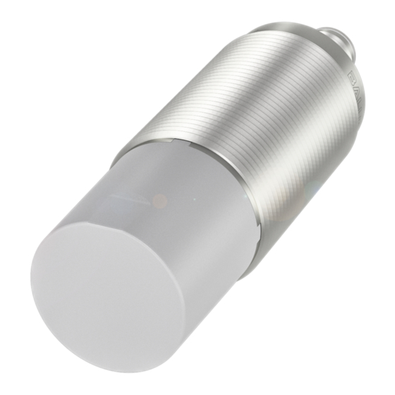
IO-Link-Devices Bild 4-1: Systemübersicht Aufbau Antennengehäuse IO-Link/Power 97.6 85.8 79.9 29.4 aktive Fläche 2 × Mutter M30 LED Status für Klemmmontage Bild 4-2: Aufbau und Funktion (am Beispiel BIS U-4A7-082-01C-07-S4) LED (4×90°) Anzugsdrehmoment ≤ 40 Nm Bild 4-3: Abmessungen BIS U-4A7-082-01C-07-S4 www.balluff.com deutsch... -
Seite 12: Funktion
BIS U-4A7-082- _1C-07-S4 Industrial RFID-System – Schreib-/Lesekopf Produktbeschreibung (Fortsetzung) Funktion Weitere Informationen zu UHF-Identifikations- systemen siehe Basishandbuch UHF unter www.balluff.com auf der Produktseite. 4.3.1 Funktionsprinzip Identifikationssysteme Der Schreib-/Lesekopf BIS U-4A7 gehört zur Kategorie der 4.3.2 Datensicherheit berührungslos arbeitenden Systeme mit Schreib- und Um Datensicherheit zu gewährleisten, wird der Datentrans-... -
Seite 13: Anzeigeelemente
Datenträgerzugriffe) Blau statisch Es muss eine Wartung durchge- führt werden. Blau blinkend 3 Hz Der Ping kann über ein System- Command aktiviert werden, um das Gerät wiederzufinden. Blau blinkend 5 Hz Reader aktiv Tab. 4-1: Bedeutung der LED-Zustände Balluff Standard www.balluff.com deutsch... -
Seite 14: Applikationsplanung
Kapitel 5.3 auf Seite 13). hen, da dieser die nötige Stabilität bietet (siehe Bild 5-3). Dazu können Halterungen aus dem Zubehörprogramm (siehe www.balluff.com auf der Produktseite) oder eigens angefertigte Träger verwendet werden. Wichtig ist dabei, Datenträger im Erfassungsbereich dass der Antennenbereich frei von leitfähigen Materialien (z. B. -
Seite 15: Multi-Reader-Umgebung
(länderabhängige Details zu Konformität und Zulassung siehe beiliegenden Informationen oder unter www.balluff.com auf der Produktseite), kann die Abschir- mung auch dadurch erreicht werden, dass benachbarte Geräte auf unterschiedlichen Kanälen (Frequenzen) arbei- ten (siehe Kapitel Kapitel 5.4 auf Seite 14). -
Seite 16: Kanalanwahl/Frequenzsprungverfahren
Auch die Umgebungstemperatur muss berücksichtigt werden. Vor allem, wenn Datenträger zum Beispiel innerhalb einer Fertigungslinie Hochtempera- turbereiche durchfahren und an der Lesestelle noch eine erhebliche Restwärme aufweisen. Für diesen Einsatzzweck können z. B. Balluff Hochtemperatur-Tags verwendet werden. deutsch... -
Seite 17: Orientierung Und Montage Von Datenträgern
Umständen nicht erreichen. Im Einzelfall muss die Reichweite des gewählten Datenträgers in der stärkere Applikation überprüft werden. Raumachse Datenträger zu den verschiedenen Anforderungen sowie Montagehalterungen siehe www.balluff.com. Datenträger vertikal orien- Datenträger horizontal orientiert: tiert: geringere Reichweite größere Reichweite Orientierung und Montage von Datenträgern Für den optimalen Betrieb des Identifikationssystems ist es... -
Seite 18: Applikation Mit Unbekannter Oder Wechselnder Datenträgerausrichtung
Wirkungsgrad als Datenträger mit träger ggf. mit einem Abstandshalter (siehe großen Abmessungen. Die oberen Leistungs- www.balluff.com) montiert werden. werte (12 dBmERP bzw. 14 dBmEIRP) sind Auch der Inhalt eines Trägers hat einen Einfluss auf die eher für kleine Datenträger gedacht und nicht, Funktion des Datenträgers. -
Seite 19: Ermitteln Der Optimalen Sendeleistung
Zuverlässigkeit abzuschätzen. werden muss, um auch Schreibvorgänge durchzuführen. Ist das AutoSetup nicht erfolgreich oder sollen viele Daten- träger erfasst werden, kann eine manuelle Einstellung mit der oben beschriebenen bottom-up-Vorgehensweise genutzt werden, um eine optimale Einstellung zu erreichen. www.balluff.com deutsch... -
Seite 20: Einfluss Der Umgebung
BIS U-4A7-082- _1C-07-S4 Industrial RFID-System – Schreib-/Lesekopf Applikationsplanung (Fortsetzung) 5.10 Einfluss der Umgebung Die Einstellung hat Einfluss auf die Dauer der Befehlsbear- beitung. Je höher der Wert des Parameters eingestellt ist, Die Umgebung hat generell einen starken Einfluss auf das desto länger ist die Antwortzeit im Fehlerfall. -
Seite 21: Funkprofile Und Deren Auswirkungen
Profil Nr. 4 (TX: 40 kbit/s, RX: 40 kBit/s, Miller-4 ) PROFINET IO-Link Initialer Q-Wert CIFX 50E-RE BNI PNT-508-105-Z015 BIS U-4A7-082-01C-07-S4 Der Q-Wert ist ein Wert, der zur internen Verar- Bild 5-14: Messaufbau Zugriffzeiten beitung verwendet wird, um Datenträger im Multi-Tag-Betrieb zeitlich gestaffelt anzuspre- Anzahl... -
Seite 22: Rx-Codierung [Fm0/Miller-N] Rx-Bitrate [Kbit/S]
Zur Verfügung stehende Funkprofile Die Verfügbarkeit der einzelnen Funkprofile ist abhängig von der verwendeten Ländervariante des BIS U-4A7, da durch nationale Bestim- mungen manche Funkprofile ausgeschlossen werden müssen. Länderabhängige Details zu Konformität und Zulassung siehe beiliegenden Informationen oder unter www.balluff.com auf der Produktseite. deutsch... -
Seite 23: Einbau Und Anschluss
Materialien ist. Kann dies nicht gewährleistet werden, kann Signale von Funktionen ausgegeben werden können (siehe Konfigurati- die optimale Funktionsweise des Schreib-/Lesekopfs onsanleitung). beeinträchtigt werden. ► Datenleitung zum IO-Link-Master anschließen (Anschlusskabel und Zubehör siehe www.balluff.com Einbau auf der Produktseite). VORSICHT Schirmung und Kabelverlegung Ultrahochfrequente elektromagnetische Wellen Für den Anschluss der Geräte können sowohl unge-... -
Seite 24: Inbetriebnahme Und Betrieb
Beschädigte Anschlüsse tauschen. Hauptfenster dargestellt (siehe Bild 7-1). 2. System einschalten. Konfigurationssoftware UHF-Manager Die Konfigurationssoftware Balluff UHF-Manager bietet die Möglichkeit, das RFID-System vor dem Einbau auf einfa- che Weise in Betrieb zu nehmen, Grundfunktionen zu testen und Parametereinstellungen vorzunehmen. Für die Inbetriebnahme mit dem UHF-Manager ist ein Balluff IO-Link-Master-Gerät mit UDP-Protokoll zu verwen-... -
Seite 25: Schnittstelleneinstellungen
Öffnet das Fenster für erweiterte Parameter (Bereich ist kennwortgeschützt, siehe Menüpunkt Benutzerebene wechseln wechseln auf Seite 23). – yStem etup Bereich ist nur für Balluff Servicemitarbeiter zugänglich. – eräte Zeigt eine Liste der unterstützten Geräte und ermögli- cht eine manuelle Auswahl. Je nach ausgewähltem Bild 7-3: Schnittstelleneinstellungen Gerät verändert sich die Benutzeroberfläche. -
Seite 26: Datenträger Erfassen/Erkennen
BIS U-4A7-082- _1C-07-S4 Industrial RFID-System – Schreib-/Lesekopf Inbetriebnahme und Betrieb (Fortsetzung) 7.2.4 Datenträger erfassen/erkennen 7.2.5 Datenträger lesen/schreiben Mit der Schaltfläche S … im Reiter e Der Reiter l stellt die Funktionen zum Ausle- uche rkennen eSen chreiBen Aktionsbereichs kann eine Datenträgerliste erstellt werden, sen sowie zum Beschreiben von Datenträgern zur Verfü- die die Datenträger auflistet, die sich im Erfassungsbereich gung. -
Seite 27: Parametereinstellung
Schmutz zu entfernen. können die Parameter auf den Schreib-/Lesekopf über- nommen werden. Um die Frontkappe des Schreib-/Lesekopfs beim Reini- gungsvorgang nicht zu beschädigen, ein weiches Tuch verwenden, jedoch keine raue Materialien. Wartung Das Produkt ist wartungsfrei. www.balluff.com deutsch... -
Seite 28: Systemintegration
BIS U-4A7-082- _1C-07-S4 Industrial RFID-System – Schreib-/Lesekopf Systemintegration IO-Link-Grundwissen Drei-Leiter-Physik IO-Link unterstützt sowohl den Kommunikationsmodus als auch den Standard-IO-Modus (SIO). Standard-IO bietet ein 8.1.1 Vorteile von IO-Link schaltendes Signal auf der Kommunikationsleitung, wie es IO-Link bietet folgende Vorteile: einfach schaltende Sensoren verwenden. Dieser Modus ist –... -
Seite 29: Identifikationsdaten Und Geräteinformation
0x06 Device ID 2 1 Byte STRING 0x03 Device ID 3 (LSB) 1 Byte STRING 0x01 Vendor Name 0x0010 (16) 7 Byte STRING “Balluff” Vendor Text 0x0011 (17) 15 Byte STRING “www.balluff.com” Product Name 0x0012 (18) 23 Byte STRING z. B. BIS U-4A7-082- 01C-07-S4 Product ID 0x0013 (19) 23 Byte... -
Seite 30: Bedarfsdaten
BIS U-4A7-082- _1C-07-S4 Industrial RFID-System – Schreib-/Lesekopf Systemintegration (Fortsetzung) Bedarfsdaten Die gerätespezifischen Parameter des Identifikationssys- tems sind über die ISDU parametrier- und auslesbar. Die Parameterdaten des BIS U-IO-Link-Device sind nach- folgend näher beschrieben. Über den Subindex 0 kann jeweils ein ganzer Index angesprochen werden. So erreicht man mit Index 0x0088 –... - Seite 31 0x00030602 0x00000902 62,5 0x00030902 62,5 0x00030C01 0x00030C02 0x00030C03 0x00060F02 Aufgrund der international unterschiedlichen Funkbestimmungen sind die verfügbaren Funkprofile abhängig von der verwendeten Ländervariante. Länderabhängige Details zu Konformität und Zulassung siehe beiliegenden Informationen oder unter www.balluff.com auf der Produktseite. www.balluff.com deutsch...
- Seite 32 BIS U-4A7-082- _1C-07-S4 Industrial RFID-System – Schreib-/Lesekopf Systemintegration (Fortsetzung) Initialer Q-Wert (erwartete Anzahl Tags) Max. EPC-Länge Parameter-ID: 0x0084 – Subindex 2 Parameter-ID: 0x0084 – Subindex 3 UHF-Manager: Menü: Geräte Einstellungen > Prame- UHF-Manager: Menü: Geräte Einstellungen > Parame- ter…> Basic UHF (Erwartete Anzahl ter…...
- Seite 33 1 (Pilotton ein) Präambel mit oder ohne Pilotton 0: Pilotton aus 1: Pilotton ein Aus Gründen der Prozesssicherheit ist es ratsam, den Pilotton eingeschaltet zu lassen. In sehr zeitkritischen Applikationen kann durch das Abschalten des Pilottones ein geringfügiger Zeitvorteil entstehen. www.balluff.com deutsch...
- Seite 34 BIS U-4A7-082- _1C-07-S4 Industrial RFID-System – Schreib-/Lesekopf Systemintegration (Fortsetzung) Automatische Erhöhung der Sendeleistung beim Schreiben Parameter-ID: 0x0084 – Subindex 9 UHF-Manager: Menü: Geräte Einstellungen > Parame- ter… > Sendeleistung Mit diesem Parameter kann festgelegt werden, ob für Schreib- und Leseoperationen dieselbe Sendeleistung verwendet wird oder ob die Sendeleistung für Schreibope- rationen um einen Offset-Wert angehoben wird.
-
Seite 35: Bedeutung
4 und 10 0x05 aktiviert, 7 und 13 deaktiviert Einstellbare Werte: Länge Zulässige Werks- Bedeutung [Bit] Werte einstellung 0x00… 0x0F Bit 0: Kanal 4 0x0F Alle Kanäle ein Bit 1: Kanal 7 Bit 2: Kanal 10 Bit 3: Kanal 13 www.balluff.com deutsch... - Seite 36 BIS U-4A7-082- _1C-07-S4 Industrial RFID-System – Schreib-/Lesekopf Systemintegration (Fortsetzung) BlockWrite aktivieren Max. Schreiblänge Parameter-ID: 0x0084 – Subindex 12 Parameter-ID: 0x0084 – Subindex 13 UHF-Manager: Menü: Geräte Einstellungen > Erwei- UHF-Manager: Menü: Geräte Einstellungen > Erwei- terte Parameter… > Luftschnittstelle terte Parameter… > Luftschnittstelle Bei gewöhnlichen Schreibzugriffen auf einen Datenträger, Die Max.
-
Seite 37: Länge Zulässige Werks
Dadurch reduziert sich die BUS-Last. Der Parameter wird als Zeitwert eingestellt, der angibt, nach welcher Zeit das Antennenfeld erneut nach Tags durchsucht wird. Die gewünschte Wiederholzeit setzt sich wie folgt zusam- men: Zeit = [Parameterwert 0x0084, Subindex 15] × [Parame- terwert 0x0084, Subindex 16] × 10 ms www.balluff.com deutsch... -
Seite 38: Temporäre Daten
BIS U-4A7-082- _1C-07-S4 Industrial RFID-System – Schreib-/Lesekopf Systemintegration (Fortsetzung) 8.3.2 Temporäre Daten Folgende Daten werden nicht auf dem EEPROM gespei- chert und werden daher nach einem Neustart/Reset wieder auf die Default-Werte gesetzt. ISDU – Temporäre Parameterdaten Name Index Subindex Zugriff Länge Datentyp Data... -
Seite 39: Auto Setup
– Tag enthält keine User-Daten. – Tags sind schreibgeschützt. – Die Maximalleistung des Geräts ist nicht ausrei- chend, um sicher zu schreiben. Die Sendeleistung 0x0084 – Subindex 8 und 0x0085 – Subindex 1 wurden gesetzt, um diesen Tag sicher erkennen und lesen zu können. www.balluff.com deutsch... -
Seite 40: Diagnose-Daten
BIS U-4A7-082- _1C-07-S4 Industrial RFID-System – Schreib-/Lesekopf Systemintegration (Fortsetzung) 8.3.3 Diagnose-Daten ISDU – Diagnos-Parameterdaten Name Index Subindex Zugriff Länge Datentyp Data Default Storage Diagnose-RFID-Parameter 0x0088 (136) 9 Byte Record – AutoSelect 1 Byte UINT8 Tag PC 6 Byte UINT8[ ] 0x0000 Temperatur Amplifier 2 Byte UINT16 AutoSelect... -
Seite 41: Speicherung Der Parameterdaten
Befehlsspezifische Werte oder Daten 0x04 Befehlsspezifische Werte oder Daten 0x05 Befehlsspezifische Werte oder Daten 0x06 Befehlsspezifische Werte oder Daten 0x07 Befehlsspezifische Werte oder Daten … … 0x1E /0x0E Befehlsspezifische Werte oder Daten 0x1F /0x0F – 2. Bitleiste Standardprofil CCM-Profil www.balluff.com deutsch... -
Seite 42: Funktionsbeschreibung
BIS U-4A7-082- _1C-07-S4 Industrial RFID-System – Schreib-/Lesekopf Systemintegration (Fortsetzung) Erklärungen zum Ausgangspuffer mit 32 Byte Prozessdaten Subadresse Bitname Bedeutung Funktionsbeschreibung 1. Bitleiste 0x00 Toggle-Bit Ein Zustandswechsel während eines Auftrags zeigt an, dass die Steue- rung bereit ist, weitere Daten zu empfangen, die der Schreib-/Lesekopf bereitgestellt hat. - Seite 43 Fehler-Code oder Daten 0x02 Daten 0x03 Daten 0x04 Daten 0x05 Daten 0x06 Daten 0x07 Daten 0x08 Daten 0x09 Daten 0x0A Daten … … 0x0E Daten 0x0F – 2. Bitleiste BB HF TO MT AF AE AA CP 0x10 CCM-Byte www.balluff.com deutsch...
- Seite 44 BIS U-4A7-082- _1C-07-S4 Industrial RFID-System – Schreib-/Lesekopf Systemintegration (Fortsetzung) Erklärungen zum Eingangspuffer mit 32 Byte Prozessdaten (Standard) Subadresse Bitname Bedeutung Funktionsbeschreibung 1. Bitleiste 0x00 betriebsbereit 1 = Gerät ist betriebsbereit 0 = Gerät ist im Grundzustand Head Failure 1 = Kopf ist abgeschaltet 0 = Kopf ist angeschaltet Toggle-Bit Ein Zustandswechsel während eines Auftrags zeigt an, dass der Schreib-/...
-
Seite 45: Protokollablauf
Der Zustand des Bit ist nur gültig, wenn die beiden Bitleis- ten den identischen Wert zeigen. Dann ist gewährleistet, dass auch die übrigen Dateninhalte aktuell sind. Auf diese Weise können alle Funktionen des Schreib-/ Lesekopfs genutzt werden (siehe Kapitel 8.7 auf Seite 44). www.balluff.com deutsch... -
Seite 46: Befehlsübersicht
BIS U-4A7-082- _1C-07-S4 Industrial RFID-System – Schreib-/Lesekopf Systemintegration (Fortsetzung) Befehlsübersicht Die Befehle werden mit dem Standardprofil (32 Byte Prozessdaten) erklärt. Wird das CCM- Profil eingestellt, verschiebt sich die 2. Bitleiste von Subadresse 0x1F auf die Subadresse 0x0F (siehe Aus-/Eingangspuffer in Kapitel 8.5). Funktion Befehlskennung Beschreibung Datenträger lesen... -
Seite 47: Befehlskennung 0X01: Datenträger Lesen
Start adresse gelesen werden (Low Byte) sollen. 0x05 Anzahl Anzahl der Bytes, die ab Bytes Start adresse gelesen werden (High Byte) sollen. 0x06… Keine Keine Bedeutung 0x1E 0x1F 2. Bitleiste Stimmen 1. und 2. Bitleiste überein, liegen gültige Daten vor. www.balluff.com deutsch... -
Seite 48: Befehlskennung 0X02: Datenträger Schreiben
BIS U-4A7-082- _1C-07-S4 Industrial RFID-System – Schreib-/Lesekopf Systemintegration (Fortsetzung) 8.7.3 Befehlskennung 0x02: Datenträger schreiben Daten werden erst entgegengenommen, wenn der Befehl quittiert wurde. Schreiben von User-Daten auf einen Datenträger, der sich Daten: im Erfassungsbereich der Antenne des Schreib-/Lesekopfs befindet. Sub- Bedeutung Funktionsbeschreibung Über Startadresse, Anzahl Bytes und Speicherbank wird... -
Seite 49: Befehlskennung 0X40: Datenträger Auswählen (Select)
1. Bitleiste 0x01 Daten 1. Byte der Datenträgerken- nung (EPC bzw. TID) … Daten Weitere Bytes der Datenträger- kennung (EPC bzw. TID) … Keine Keine Bedeutung 0x1F 2. Bitleiste Stimmen 1. und 2. Bitleiste überein, liegen gültige Daten vor. www.balluff.com deutsch... -
Seite 50: Befehlskennung 0X42: Epc Lesen
BIS U-4A7-082- _1C-07-S4 Industrial RFID-System – Schreib-/Lesekopf Systemintegration (Fortsetzung) 8.7.6 Befehlskennung 0x42: EPC lesen Liest den EPC eines Datenträgers, der sich im Erfassungs- bereich der Antenne des Schreib-/Lesekopfs befindet. Befinden sich mehrere Datenträger im Erfassungsbereich, muss der gewünschte Datenträger vor dem Lesen selek- tiert werden (Befehlskennung 0x40, siehe Kapitel 8.7.4 auf Seite 47). -
Seite 51: Befehlskennung 0X43: Epc Schreiben
Übertragung der EPC-Daten, die in den Datenträger geschrieben werden sollen. 0x02 EPC-Daten Übertragung der EPC-Daten, die in den Datenträger geschrieben werden sollen. … Keine Keine Bedeutung 0x1F 2. Bitleiste Stimmen 1. und 2. Bitleiste überein, liegen gültige Daten vor. www.balluff.com deutsch... -
Seite 52: Befehlskennung 0X44: Tid Lesen
BIS U-4A7-082- _1C-07-S4 Industrial RFID-System – Schreib-/Lesekopf Systemintegration (Fortsetzung) 8.7.8 Befehlskennung 0x44: TID lesen Liest die TID eines Datenträgers, der sich im Erfassungs- bereich der Antenne des Schreib-/Lesekopfs befindet. Die Länge der gelesenen TID-Daten wird über den Parameter 0x0084 – Subindex 4 festgelegt (TID-Länge siehe Seite 30). -
Seite 53: Befehlskennung 0X47: Datenträger Erfassen Und Lesen (Get Taglist)
12 Byte je EPC (Darstellung ohne Bit-Leisten): EPC 1 EPC 2 Daten 000000: 02 0c 27 01 03 e2 22 90 11 e2 00 00 ff e2 be c5 000010: 80 07 74 01 05 32 51 90 00 e2 www.balluff.com deutsch... - Seite 54 BIS U-4A7-082- _1C-07-S4 Industrial RFID-System – Schreib-/Lesekopf Systemintegration (Fortsetzung) Werden die EPC mit der Länge 64 Byte übertragen, sieht Beispiel die Antwort im Eingangspuffer wie folgt aus: Beispiel mit 32 Byte Prozessdaten eines empfangenen Datenrahmens mit zwei EPCs und 64 Byte je EPC (Dar- Sub- Bedeutung Funktionsbeschreibung...
-
Seite 55: 8.7.10 Befehlskennung 0X50: Kill
überein, liegen gültige Daten vor. Antwort: Sub- Bedeutung Funktionsbeschreibung adresse 0x00 1. Bitleiste 0x01 Statuscode Gibt Aufschluss über den Status einer Anfrage. … Keine Keine Bedeutung 0x1F 2. Bitleiste Stimmen 1. und 2. Bitleiste überein, liegen gültige Daten vor. www.balluff.com deutsch... -
Seite 56: Befehlskennung 0X53: Bulk Read
BIS U-4A7-082- _1C-07-S4 Industrial RFID-System – Schreib-/Lesekopf Systemintegration (Fortsetzung) 8.7.11 Befehlskennung 0x53: Bulk Read Sub- Bedeutung Funktionsbeschreibung adresse Auslesen der User-Daten von mehreren Datenträgern, die sich im Erfassungsbereich der Antenne befinden. Über die 0x04 Daten 1 [0] Übertragung des 1. Byte, das Datenträger auswahl können wahlweise alle Datenträger im vom 1. Datenträger gelesen Erfassungsbereich ausgelesen werden oder nur eine... -
Seite 57: 8.7.12 Befehlskennung 0X54: Bulk Write
Gibt Aufschluss über den … Keine Keine Bedeutung Status einer Anzeige 0x1F 2. Bitleiste Stimmen 1. und 2. Bitleiste … Keine Keine Bedeutung überein, liegen gültige Daten 0x1F 2. Bitleiste Stimmen 1. und 2. Bitleiste vor. überein, liegen gültige Daten vor. www.balluff.com deutsch... -
Seite 58: 8.7.13 Befehlskennung 0X55: Anzahl Datenträger
BIS U-4A7-082- _1C-07-S4 Industrial RFID-System – Schreib-/Lesekopf Systemintegration (Fortsetzung) 8.7.13 Befehlskennung 0x55: Anzahl Datenträger Erfasst die Datenträger, die sich im Erfassungsbereich der Antenne befinden und gibt die Anzahl der erkannten Datenträger zurück. Mit der Datenträger auswahl können wahlweise alle oder nur selektierte Datenträger erfasst werden. -
Seite 59: Befehlskennung 0X56: Auslesen Des Rssis (Receive Signal Strength Indicator)
überein, liegen gültige Daten vor. oder Eingangspuffer: Statusmeldung Sub- Bedeutung Funktionsbeschreibung adresse 0x00 1. Bitleiste 0x01 Statuscode Gibt Aufschluss über den Status einer Anfrage. … Keine Keine Bedeutung 0x1F 2. Bitleiste Stimmen 1. und 2. Bitleiste überein, liegen gültige Daten vor. www.balluff.com deutsch... -
Seite 60: Status Lesen
BIS U-4A7-082- _1C-07-S4 Industrial RFID-System – Schreib-/Lesekopf Systemintegration (Fortsetzung) Befehlskennung 0x57: Lock Lock-Status der Speicherbereiche EPC, TID, USER Mit dem l -Befehl können Speicherbereiche (Access- Der Speicherbereich TID ist unabhängig vom Password, Kill-Password, EPC, TID, USER) eines UHF- Lock-Status grundsätzlich schreibgeschützt Datenträgers für Schreib- oder Lesezugriffe sowie für und kann nur gelesen werden. -
Seite 61: Befehlskennung 0X59: Datenträger Erfassen Und Lesen, Erweitert (Tag List Extended)
PC (Low Byte) Protocol Control Word Low Byte … XPC1 (High Byte) XPC Word 1 High Byte … XPC1 (Low Byte) XPC Word 1 Low Byte … XPC2 (High Byte) XPC Word 2 High Byte … XPC2 (Low Byte) XPC Word 2 Low Byte www.balluff.com deutsch... -
Seite 62: Funktionsbeschreibung
BIS U-4A7-082- _1C-07-S4 Industrial RFID-System – Schreib-/Lesekopf Systemintegration (Fortsetzung) Sub- Bedeutung Funktionsbeschreibung adresse … EPC n Länge MSB EPC Länge (ASCII) … EPC n Länge LSB EPC Länge (ASCII) … EPC n EPC-Daten höchste Adresse … … … … EPC n EPC-Daten niedrigste Adresse …... -
Seite 63: Befehlskennung 0X60: Schnelle Tag-Identifikation
Antwort übergeben. Sub- Bedeutung Funktionsbeschreibung adresse 0x00 1. Bitleiste 0x01 Statuscode Gibt Aufschluss über den Status einer Anfrage. … Keine Keine Bedeutung 0x1F 2. Bitleiste Stimmen 1. und 2. Bitleiste überein, liegen gültige Daten vor. www.balluff.com deutsch... -
Seite 64: Fehlercodes
BIS U-4A7-082- _1C-07-S4 Industrial RFID-System – Schreib-/Lesekopf Systemintegration (Fortsetzung) Fehlercodes Status- Funktionsbeschreibung code 0x00 Alles in Ordnung. 0x01 Auftrag kann nicht ausgeführt werden, da kein Datenträger im Bereich des Schreib-/ Lesekopfs. 0x02 Lesen des Datenträgers nicht möglich. 0x03 Datenträger wurde während des Lesens aus dem Bereich des Schreib-/Lesekopfs ent- fernt. -
Seite 65: Beispiele
Weitere 30 Byte kopieren 0x00/0x1F AA-Bit setzen Ausgangspuffer bearbeiten: 0x01…0x02 Letzte 2 Byte eintragen 0x00/0x1F TI-Bit invertieren 0x00/0x1F TO-Bit invertieren 0x00/0x1F AE-Bit setzen Eingangspuffer bearbeiten: Eingangspuffer bearbeiten: 0x01…0x02 Letzte 2 Byte kopieren 0x00/0x1F AA-Bit rücksetzen Ausgangspuffer bearbeiten: 0x00/0x1F AE-Bit rücksetzen 0x00/0x1F AV-Bit rücksetzen www.balluff.com deutsch... - Seite 66 BIS U-4A7-082- _1C-07-S4 Industrial RFID-System – Schreib-/Lesekopf Systemintegration (Fortsetzung) Lesen von 62 Byte an Schreib-/Lesekopf, Startadresse 10, Problem beim Lesen Tritt ein Problem auf, wird das AF-Bit an Stelle des AE-Bit mit entsprechender Statusnummer zugestellt. Mit dem Setzen des AF-Bit wird der Auftrag unterbrochen und als beendet erklärt.
- Seite 67 Eingangspuffer bearbeiten: Wenn Problem eingetreten ist! 0x01…0x1E Erste 30 Byte kopieren 0x01 Statusnummer eintragen Ausgangspuffer bearbeiten: 0x00/0x1F AF-Bit setzen 0x00/0x1F TI-Bit invertieren Eingangspuffer bearbeiten: Eingangspuffer bearbeiten: 0x01 Statusnummer kopieren 0x00/0x1F AA und AF-Bit rücksetzen Ausgangspuffer bearbeiten: 0x00/0x1F AV-Bit rücksetzen www.balluff.com deutsch...
- Seite 68 BIS U-4A7-082- _1C-07-S4 Industrial RFID-System – Schreib-/Lesekopf Systemintegration (Fortsetzung) Schreiben von 62 Byte an Schreib-/Lesekopf, Startadresse 20 Steuerung Identifikationssystem Ausgangspuffer bearbeiten Eingangspuffer bearbeiten (Reihenfolge beachten): (Reihenfolge beachten): 0x01 Befehlskennung 0x02 0x00/0x1F AA-Bit setzen 0x02 Startadresse 0x14 0x00/0x1F TO-Bit invertieren 0x03 Startadresse 0x00 0x04 Anzahl Bytes 0x3E 0x05...
- Seite 69 ⇒ Schreib-/Lesekopf ist eingeschaltet Schreib-/Lesekopfantenne ausschalten Im Normalbetrieb sind alle Schreib-/Lesekopfantennen angeschaltet. Durch Setzen des KA-Bit kann die Antenne des jeweiligen Schreib-/Lesekopfs ausgeschaltet werden. Steuerung Ausgangspuffer bearbeiten: 0x00/0x1F KA-Bit setzen Durch Rücksetzen des KA-Bit wird die Antenne des Schreib-/Lesekopfs wieder angeschaltet. www.balluff.com deutsch...
- Seite 70 BIS U-4A7-082- _1C-07-S4 Industrial RFID-System – Schreib-/Lesekopf Systemintegration (Fortsetzung) Lesen der EPCs mehrerer Datenträger vor der Antenne (bei Konfiguration mit 32 Byte Puffergröße) Startparameter: – 5 Datenträger – 3 erkannt (wie beschrieben) Steuerung Identifikationssystem Ausgangspuffer bearbeiten Eingangspuffer bearbeiten (Reihenfolge beachten): (Reihenfolge beachten): 0x01 Befehlskennung 0x47 0x00/0x1F...
- Seite 71 Länge des EPC 0x0C 0x00/0x1F AV-Bit setzen Ausgangspuffer bearbeiten: Ausgangspuffer bearbeiten: 0x01…0x0C 12 Byte EPC eintragen 0x01…0x0C EPC abspeichern 0x00/0x1F TI-Bit invertieren Eingangspuffer bearbeiten: 0x00/0x1F AE-Bit setzen Ausgangspuffer bearbeiten: Eingangspuffer bearbeiten: 0x00/0x1F AV-Bit rücksetzen 0x00/0x1F AA- und AE-Bit rücksetzen www.balluff.com deutsch...
- Seite 72 BIS U-4A7-082- _1C-07-S4 Industrial RFID-System – Schreib-/Lesekopf Systemintegration (Fortsetzung) Unselect Aufheben einer Datenträger auswahl, die mit dem Select- Befehl getroffen wurde. Steuerung Identifikationssystem Ausgangspuffer bearbeiten Eingangspuffer bearbeiten (Reihenfolge beachten): (Reihenfolge beachten): 0x01 Befehlskennung 0x41 0x00/0x1F AA-Bit setzen 0x00/0x1F AV-Bit setzen 0x00/0x1F AE-Bit setzen Ausgangspuffer bearbeiten:...
- Seite 73 Anzahl gefundener Tags eintragen 0x02 Anzahl erfolgreich geschriebener Tags eintragen 0x00/0x1F AE-Bit setzen Eingangspuffer bearbeiten: Eingangspuffer bearbeiten: 0x01 Anzahl gefundener Tags kopieren 0x00/0x1F AA und AE-Bit rücksetzen 0x02 Anzahl erfolgreich geschriebener Tags kopieren Ausgangspuffer bearbeiten: 0x00/0x1F AV-Bit rücksetzen www.balluff.com deutsch...
- Seite 74 BIS U-4A7-082- _1C-07-S4 Industrial RFID-System – Schreib-/Lesekopf Systemintegration (Fortsetzung) 11. Bulk Read Lesen von allen Datenträgern, die sich vor der Antenne befinden. Lesen von 4 Byte ab Datenträgeradresse 3 für den Fall, dass 4 Datenträger gefunden werden. Steuerung Identifikationssystem Ausgangspuffer bearbeiten Eingangspuffer bearbeiten (Reihenfolge beachten): (Reihenfolge beachten): 0x01...
- Seite 75 AV setzen 0x06 0x1C: EPC-Daten … EPC-Daten 0x1C 0x06: EPC-Daten 0x1D 0x05: EPC-Daten 0x1E 0x04: EPC-Daten 0x00/0x1F AA und AE setzen Ausgangspuffer bearbeiten: Empfangene Daten kopieren, Subadressen des Eingangspuffers bearbeiten: 0x00/0x1F AV löschen 0x00/0x1F AA und AE löschen www.balluff.com deutsch...
- Seite 76 BIS U-4A7-082- _1C-07-S4 Industrial RFID-System – Schreib-/Lesekopf Systemintegration (Fortsetzung) 13. Schnelle Tag-Identifizierung – 28 höchstwertige EPC-Byte, alternative Reihenfolge Beispiel mit 32 Byte EPC: EPC: e0 01 02 03 04 05 06 07 08 09 0a 0b 0c 0d 0e 0f 10 11 12 13 14 15 16 17 18 19 1a 1b 1c 1d 1e 1f Höchstwertige 28 Byte: e0 01 02 03 04 05 06 07 08 09 0a 0b 0c 0d 0e 0f 10 11 12 13 14 15 16 17 18 19 1a 1b 1c 1d 1e 1f...
- Seite 77 AV setzen 0x06 0x18: EPC-Daten … EPC-Daten 0x1C 0x02: EPC-Daten 0x1D 0x01: EPC-Daten 0x1E 0xE0: EPC-Daten 0x00/0x1F AA und AE setzen Subadressen bearbeiten: Empfangene Daten kopieren, Subadressen des Eingangspuffers bearbeiten: 0x00/0x1F AV löschen 0x00/0x1F AA und AE löschen www.balluff.com deutsch...
-
Seite 78: Zeitlicher Ablauf Der Datenübertragung
BIS U-4A7-082- _1C-07-S4 Industrial RFID-System – Schreib-/Lesekopf Systemintegration (Fortsetzung) 8.10 Zeitlicher Ablauf der Datenübertragung In der folgenden Abbildung ist der zeitliche Ablauf der IO-Link Kommunikation zu sehen. Es werden immer abwechselnd Ein- und Ausgangspuffer ausgetauscht. Sobald aktuelle Daten in einem der Puffer anstehen, werden diese mit dem nächsten beginnenden In- bzw. - Seite 79 Auftrag gehörenden Bits in den Bitleisten im Eingangs- 5. Nach einer erneuten Synchronisationszeit t5 werden puffer. die ersten Daten mit dem nächsten In-Data-Cycle an den IO-Link-Master weitergegeben. Außerdem wird das AE-Bit in den Bitleisten gesetzt. Die Zeit hierfür ist t7 = 1 x Zykluszeit. www.balluff.com deutsch...
-
Seite 80: Störungen, Reparatur, Demontage Und Entsorgung
Systemintegrator nicht behoben werden können, muss Kontakt mit dem Balluff Service aufgenommen werden. Reparatur ► Reparaturen am Produkt dürfen nur von Balluff durch- geführt werden. ► Sollte das Produkt defekt sein, nehmen Sie Kontakt mit unserem Service-Center auf. -
Seite 81: Technische Daten
20 dBmEIRP Antennenpolarisation Zirkular Funkmerkmale (abgestrahlte Leistung, Anten- nengewinn, etc.) sind aufgrund unterschied- licher nationaler Bestimmungen länderspezifisch und hängen von der Gerätevariante ab. Länderabhängige Details zu Konformität und Zulassung siehe beiliegenden Informationen oder unter www.balluff.com auf der Pro- duktseite. www.balluff.com deutsch... -
Seite 82: Zulassungen Und Kennzeichnungen
BIS U-4A7-082- _1C-07-S4 Industrial RFID-System – Schreib-/Lesekopf Technische Daten (Fortsetzung) 10.7 Zulassungen und Kennzeichnungen Siehe beiliegendes Informationsblatt zu Konformität und Zulassung. Nähere Informationen zu Richtlinien, Zulas- sungen und Normen finden Sie unter www.balluff.com auf der Produktseite. deutsch... -
Seite 83: Typenschlüssel
BIS U-4A7-082- _1C-07-S4 Industrial RFID-System – Schreib-/Lesekopf Typenschlüssel BIS U-4A7-082-01C-07-S4 Typ: Schreib-/Lesekopf mit Auswertung Anforderungsprofil: Washdown Gehäuseform: M30-Gewinderohr Schnittstelle: 082 = IO-Link-Schnittstelle Ländervariante: Europa, Frequenzbereich 865,6…867,6 MHz USA/Kanada/Mexico, Frequenzbereich 902…928MHZ China, Frequenzbereich 920,5…924,5 MHZ Brasilien, Frequenzbereich 902…907,5 MHz und 915…928 MHz Rep. -
Seite 84: Anhang
BIS U-4A7-082- _1C-07-S4 Industrial RFID-System – Schreib-/Lesekopf Anhang Dezimal Hexa- Control ASCII Dezimal Hexa- ASCII Dezmal Hexa- ASCII dezimal Code dezimal dezimal Ctrl @ Ctrl A Ctrl B Ctrl C Ctrl D Ctrl E Ctrl F Ctrl G Ctrl H Ctrl I Ctrl J Ctrl K... - Seite 85 BIS U-4A7-082-01C-07-S4 BIS U-4A7-082-11C-07-S4 BIS U-4A7-082-21C-07-S4 User’s Guide english...
- Seite 86 www.balluff.com...
- Seite 87 Determining the optimum transmitting power 5.10 Influence of the environment 5.11 Setting the read and capture repetitions 5.12 Static and dynamic applications 5.13 Radio profiles and their effects Installation and connection Preparing for installation Installation Electrical connection Shielding and cable routing www.balluff.com english...
- Seite 88 BIS U-4A7-082- _1C-07-S4 Industrial RFID system - Read/write head Startup and operation Startup UHF Manager configuration software 7.2.1 Install and start configuration software 7.2.2 User interface 7.2.3 Interface settings 7.2.4 Detect data carriers 7.2.5 Read/write data carrier 7.2.6 Parameter setting Operation Operating notes Cleaning...
- Seite 89 BIS U-4A7-082- _1C-07-S4 Industrial RFID system - Read/write head Technical data 10.1 General features 10.2 Ambient conditions 10.3 Electrical data 10.4 Electrical connection 10.5 Output / Interface 10.6 Mechanical data 10.7 Approvals and designations Type code Appendix www.balluff.com english...
-
Seite 90: About This Guide
Other applicable documents word CAUTION indicates a hazard which can lead to slight or moderate injuries. Additional information about this product can be found at www.balluff.com on the product page, e.g. in the following documents: Technical terms and abbreviations used –... -
Seite 91: Safety Notes
Flawless function in accordance with the specifications in the technical data is ensured only when using suitable original Balluff accessories. Use of any other components will void the warranty. Non-approved use is not permitted and will result in the loss of warranty and liability claims against the manufacturer. -
Seite 92: Scope Of Delivery, Transport And Storage
Installation guide Accessories are not included in the scope of delivery and must be ordered separately. Recommended accessories can be found at www.balluff.com on the product page. Transport ► Transport product to location of use in original packaging. Storage conditions ►... -
Seite 93: Product Description
Antenna housing IO-Link / Power 97.6 85.8 79.9 29.4 Active surface 2 × nut M30 Status LED for clamp mounting Fig. 4-2: Design and function (using the example BIS U-4A7-082-01C-07-S4) LED (4×90°) Tightening torque ≤ 40 Nm Fig. 4-3: Dimensions BIS U-4A7-082-01C-07-S4 www.balluff.com english... -
Seite 94: Function
Industrial RFID system - Read/write head Product description (continued) Function For more information on UHF identification systems, see the UHF basic manual at www.balluff.com on the product page. 4.3.1 Functional principle of identification systems The BIS U-4A7 read/write head belongs to the category of 4.3.2 Data security non-contact systems with read/write function. -
Seite 95: Display Elements
Blue, static Maintenance must be performed. Blue, flashing, 3 Hz The ping can be activated via a system command to find the device again. Blue, flashing, 5 Hz Reader active Tab. 4-1: Meaning of the Balluff Standard LED states www.balluff.com english... -
Seite 96: Application Planning
Construction zones Only the M30 body is intended for mounting, as this provides the necessary stability (see Fig. 5-3). Brackets from the accessories range (see www.balluff.com on the Data carrier in detection range product page) or specially manufactured supports can be used for this purpose. -
Seite 97: Multi-Reader Environment
For BIS U-4A7 country variants that allow direct channel selection (for country-specific details on conformity and approval, see enclosed information or visit www.balluff.com on the product page), shielding can also be achieved by having adjacent devices operate on different channels (frequencies) (see chapter 5.4 on page 14). -
Seite 98: Channel Selection/Frequency Hopping
This is particularly important when data carriers pass through high-temperature areas within a production line, for example, and still have a considerable amount of residual heat at the reading point. Balluff high- temperature tags, for example, can be used for this application. -
Seite 99: Orientation And Mounting Of Data Carriers
Stronger spatial must be checked in the application. axis For data carriers that meet the various requirements and mounting brackets, see www.balluff.com. Data carrier vertically Data carrier horizontally oriented: Orientation and mounting of data carriers oriented: shorter range... -
Seite 100: Mounting Of Data Carriers
The upper the data carrier can be mounted with a spacer (see power values (12 dBmERP or 14 dBmEIRP) are www.balluff.com) if necessary. intended more for small data carriers and not to further increase the range of large data carriers. -
Seite 101: Determining The Optimum Transmitting Power
If the AutoSetup is unsuccessful or if a large number of data carriers are to be detected, manual setting with the bottom-up procedure described above can be used to achieve an optimum setting. www.balluff.com english... -
Seite 102: Influence Of The Environment
BIS U-4A7-082- _1C-07-S4 Industrial RFID system - Read/write head Application planning (continued) 5.10 Influence of the environment The setting depends on the application: – For dynamic and time-critical applications, a small The environment in general has a strong influence on the parameter value should be selected. -
Seite 103: Radio Profiles And Their Effects
IO-Link parameter can be found in chapter 8.3.1 on page 28. For details on radio profiles, see chapter 5.13 on page 19. CIFX 50E-RE BNI PNT-508-105-Z015 BIS U-4A7-082-01C-07-S4 Fig. 5-14: Access time measurement setup 5.13 Radio profiles and their effects Number Measured time Measured time... - Seite 104 The availability of the individual radio profiles depends on the country variant of the BIS U-4A7 used, as national regulations require some radio profiles to be excluded. For country-specific details on conformity and approval, see the enclosed information or www.balluff.com on the product page. english...
-
Seite 105: Installation And Connection
(see configuration guide). may be impaired. ► Connect data line to IO-Link master (for connection Installation cables and accessories, see www.balluff.com on the product page). CAUTION Shielding and cable routing Ultra high frequency electromagnetic waves... -
Seite 106: Startup And Operation
The Balluff UHF Manager configuration software provides an easy way to start up the RFID system, test basic functions and make parameter settings before installation. A Balluff IO-Link master device with UDP protocol must be used for commissioning with the UHF-Manager. 7.2.1... -
Seite 107: Program Settings
Switch user level on page 23). – yStem SetuP Area is only accessible to Balluff service staff. – evice tyPe Shows a list of supported devices and allows manual selection. Depending on the selected device, the user Fig. -
Seite 108: Detect Data Carriers
BIS U-4A7-082- _1C-07-S4 Industrial RFID system - Read/write head Startup and operation (continued) 7.2.4 Detect data carriers 7.2.5 Read/write data carrier The S button in the S tab of the action area can be The r tab provides the functions for reading out tart write used to create a data carrier list that lists the data carriers... -
Seite 109: Parameter Setting
All ECOLAB cleaning agents can be used to remove dirt. To avoid damaging the front cap of the read/write head during the cleaning process, use a soft cloth, but do not use rough materials. Maintenance The product is maintenance-free. www.balluff.com english... -
Seite 110: System Integration
BIS U-4A7-082- _1C-07-S4 Industrial RFID system - Read/write head System integration Basic knowledge about IO-Link Three-wire physics IO-Link supports both communication mode and standard IO (SIO) mode. Standard IO provides a switching signal on 8.1.1 Advantages of IO-Link the communication line, as used by simple switching IO-Link offers the following advantages: sensors. -
Seite 111: Identification Data And Device Information
0x06 Device ID 2 1 byte STRING 0x03 Device ID 3 (LSB) 1 byte STRING 0x01 Vendor Name 0x0010 (16) 7 bytes STRING “Balluff” Vendor Text 0x0011 (17) 15 bytes STRING “www.balluff.com” Product Name 0x0012 (18) 23 bytes STRING e.g. BIS U-4A7-082- 01C-07-S4 Product ID 0x0013 (19) 23 bytes... -
Seite 112: Requirement Data
BIS U-4A7-082- _1C-07-S4 Industrial RFID system - Read/write head System integration (continued) Requirement data The device-specific parameters of the identification system can be parameterized and read out via the ISDU. The parameter data of the BIS U-IO-Link device are described in more detail below. The subindex 0 can be used to address an entire index. - Seite 113 0x00030C02 0x00030C03 0x00060F02 Due to the different international radio regulations, the available radio profiles depend on the country variant used. For country- specific details on conformity and approval, see the enclosed information or www.balluff.com on the product page. www.balluff.com english...
- Seite 114 BIS U-4A7-082- _1C-07-S4 Industrial RFID system - Read/write head System integration (continued) Initial Q-value (expected number of tags) Max. EPC length Parameter-ID: 0x0084 – Subindex 2 Parameter-ID: 0x0084 – Subindex 3 UHF-Manager: Menu: Device Settings > UHF-Manager: Menu: Device settings > Parameters... Parameters...>...
- Seite 115 0: Pilot tone off 1: Pilot tone on For reasons of process reliability, it is advisable to leave the pilot tone switched on. In very time-critical applications, switching off the pilot tone may result in a slight time advantage. www.balluff.com english...
- Seite 116 BIS U-4A7-082- _1C-07-S4 Industrial RFID system - Read/write head System integration (continued) Automatic increase of transmitting power on write Parameter-ID: 0x0084 – Subindex 9 UHF-Manager: Menu: Device settings > Parameters... > Transmitting power This parameter can be used to specify whether the same transmitting power is used for write and read operations or whether the transmitting power is increased by an offset value for write operations.
- Seite 117 Bit 3 Bit 2 Bit 1 Bit 0 Byte assignment Bit 4 4 and 10 0x05 activated, 7 and 13 deactivated Adjustable values: Length Permissible Factory Meaning [bits] values setting 0x00…0x0F 0x0F Bit 0: All channels Channel 4 Bit 1: Channel 7 Bit 2: Channel 10 Bit 3: Channel 13 www.balluff.com english...
- Seite 118 BIS U-4A7-082- _1C-07-S4 Industrial RFID system - Read/write head System integration (continued) Activate BlockWrite Max. write length Parameter-ID: 0x0084 – Subindex 12 Parameter-ID: 0x0084 – Subindex 13 UHF-Manager: Menu: Device Settings > Advanced UHF-Manager: Menu: Device Settings > Advanced parameters... > Air interface parameters...
- Seite 119 The desired repetition time is composed as follows: Time = [Parameter value 0x0084, subindex 15] × [Parameter value 0x0084, subindex 16] × 10 ms Length Permissible Factory Meaning [bits] values setting 0x00 0: Automatic 1…255 scanning off 1...255: Parameter value × 0.5 s = (0.5...127.5 s) www.balluff.com english...
-
Seite 120: Temporary Data
BIS U-4A7-082- _1C-07-S4 Industrial RFID system - Read/write head System integration (continued) 8.3.2 Temporary data The following data are not stored on the EEPROM and are therefore reset to the default values after a restart/reset. ISDU – Temporary parameter data Name Index Subindex... - Seite 121 – Tag does not contain user data. – Tags are read-only. – The maximum power of the device is not sufficient to write reliably. The transmitting power 0x0084 – subindex 8 and 0x0085 – subindex 1 have been set to reliably detect and read this tag. www.balluff.com english...
-
Seite 122: Diagnostic Data
BIS U-4A7-082- _1C-07-S4 Industrial RFID system - Read/write head System integration (continued) 8.3.3 Diagnostic data ISDU – Diagnostic parameter data Name Index Subindex Access Length Data type Data Storage Default Diagnostic RFID parameters 0x0088 (136) 9 bytes Record – AutoSelect 1 byte UINT8 Tag PC 6 bytes... -
Seite 123: Storage Of The Parameter Data
Command-specific values or data 0x04 Command-specific values or data 0x05 Command-specific values or data 0x06 Command-specific values or data 0x07 Command-specific values or data … … 0x1E /0x0E Command-specific values or data 0x1F /0x0F – 2nd bit string Standard profile CCM profile www.balluff.com english... -
Seite 124: Functional Description
BIS U-4A7-082- _1C-07-S4 Industrial RFID system - Read/write head System integration (continued) Explanation of the output buffer with 32 bytes of process data Subaddress Bit name Meaning Functional description 1st bit string 0x00 Toggle bit A state change during an assignment indicates that the controller is ready to receive further data provided by the read/write head. - Seite 125 0x02 Data 0x03 Data 0x04 Data 0x05 Data 0x06 Data 0x07 Data 0x08 Data 0x09 Data 0x0A Data … … 0x0E Data 0x0F – 2nd bit BB HF TO MT AF AE AA CP string 0x10 CCM byte www.balluff.com english...
- Seite 126 BIS U-4A7-082- _1C-07-S4 Industrial RFID system - Read/write head System integration (continued) Explanation of the input buffer with 32 bytes of process data (standard) Subaddress Bit name Meaning Functional description 1st bit string 0x00 Operational 1 = Device is ready for operation 0 = Device is in default state Head failure 1 = Head is switched off...
-
Seite 127: Protocol Sequence
The status of the bit is only valid if the two bit strings show an identical value. Then it is guaranteed that the remaining data contents are also current. All of the functions of the read/write head can be used in this way (see chapter 8.7 on page 44). www.balluff.com english... -
Seite 128: Command Overview
BIS U-4A7-082- _1C-07-S4 Industrial RFID system - Read/write head System integration (continued) Command overview The commands are explained with the standard profile (32 bytes of process data). If the CCM profile is set, the 2nd bit string moves from subaddress 0x1F to subaddress 0x0F (see output/input buffer in chapter 8.5). -
Seite 129: Command Identifier 0X01: Read Data Carrier
(Low Byte) 0x05 Number of Number of bytes to be bytes read from start address. (High Byte) 0x06…0x1E None No meaning 0x1F 2nd bit If the 1st and 2nd bit string strings match, valid data is present. www.balluff.com english... -
Seite 130: Command Identifier 0X02: Write Data Carrier
BIS U-4A7-082- _1C-07-S4 Industrial RFID system - Read/write head System integration (continued) 8.7.3 Command identifier 0x02: Write data carrier Data is only accepted when the command has been acknowledged. Writing user data to a data carrier that is within the Data: detection range of the antenna of the read/write head. -
Seite 131: Command Identifier 0X40: Select Data Carrier (Select)
1st byte of the data carrier identifier (EPC or TID) … Data Other bytes of the data carrier identifier (EPC or TID) … None No meaning 0x1F 2nd bit If the 1st and 2nd bit string strings match, valid data is present. www.balluff.com english... -
Seite 132: Command Identifier 0X42: Read Epc
BIS U-4A7-082- _1C-07-S4 Industrial RFID system - Read/write head System integration (continued) 8.7.6 Command identifier 0x42: Read EPC Reads the EPC of a data carrier that is within the detection range of the antenna of the read/write head. If there are several data carriers in the detection range, the desired data carrier must be selected before reading (command identifier 0x40, see chapter 8.7.4 on page 47). -
Seite 133: Command Identifier 0X43: Write Epc
0x02 EPC data Transfer of the EPC data to be written to the data carrier. … None No meaning 0x1F 2nd bit If the 1st and 2nd bit string strings match, valid data is present. www.balluff.com english... -
Seite 134: Command Identifier 0X44: Read Tid
BIS U-4A7-082- _1C-07-S4 Industrial RFID system - Read/write head System integration (continued) 8.7.8 Command identifier 0x44: Read TID Reads the TID of a data carrier that is located in the detection range of the antenna of the read/write head. The length of the read TID data is defined via parameter 0x0084 – subindex 4 (TID length see page 30). -
Seite 135: Command Identifier 0X47: Detect And Read Data Carriers (Get Taglist)
12 bytes per EPC (display without bit strings): EPC 1 EPC 2 Data 000000: 02 0c 27 01 03 e2 22 90 11 e2 00 00 ff e2 be c5 000010: 80 07 74 01 05 32 51 90 00 e2 www.balluff.com english... - Seite 136 BIS U-4A7-082- _1C-07-S4 Industrial RFID system - Read/write head System integration (continued) If the EPCs are transmitted with the length 64 bytes, the Example response in the input buffer looks as follows: Example with 32 bytes of process data of a received data frame with two EPCs and 64 bytes per EPC (display Subaddress Meaning...
-
Seite 137: 8.7.10 Command Identifier 0X50: Kill
Meaning Functional description 0x00 1st bit string 0x01 Status code Provides information about the status of a request. … None No meaning 0x1F 2nd bit If the 1st and 2nd bit string strings match, valid data is present. www.balluff.com english... -
Seite 138: 8.7.11 Command Identifier 0X53: Bulk Read
BIS U-4A7-082- _1C-07-S4 Industrial RFID system - Read/write head System integration (continued) 8.7.11 Command identifier 0x53: Bulk Read Subaddress Meaning Functional description Read user data from several data carriers located in the 0x04 Data 1 [0] Transmission of the detection range of the antenna. Via the data carrier 1st byte read from the selection, all data carriers in the detection range can be 1st data carrier. -
Seite 139: 8.7.12 Command Identifier 0X54: Bulk Write
No meaning … None No meaning 0x1F 2nd bit If the 1st and 2nd bit 0x1F 2nd bit If the 1st and 2nd bit string strings match, valid data is string strings match, valid data present. is present. www.balluff.com english... -
Seite 140: Command Identifier 0X55: Number Of Data Carriers
BIS U-4A7-082- _1C-07-S4 Industrial RFID system - Read/write head System integration (continued) 8.7.13 Command identifier 0x55: Number of data carriers Detects the data carriers that are within the detection range of the antenna and returns the number of detected data carriers. With the data carrier selection, either all or only selected data carriers can be detected. -
Seite 141: Command Identifier 0X56: Read Rssi (Receive Signal Strength Indicator)
Subaddress Meaning Functional description 0x00 1st bit string 0x01 Status code Provides information about the status of a request. … None No meaning 0x1F 2nd bit string If the 1st and 2nd bit strings match, valid data is present. www.balluff.com english... - Seite 142 BIS U-4A7-082- _1C-07-S4 Industrial RFID system - Read/write head System integration (continued) Command identifier 0x57: Lock Lock status of the memory areas EPC, TID, USER The L command can be used to lock memory areas The TID memory area is always write-protected (access password, kill password, EPC, TID, USER) of a regardless of the lock status and can only be UHF data carrier against write or read accesses, as well as...
-
Seite 143: Command Identifier 0X59: Detect And Read Data Carriers, Extended (Tag List Extended)
EPC lowest address … RSSI EPC 1 Tag RSSI … Reserved Reserved … PC (High Byte) Protocol Control Word High Byte … PC (Low Byte) Protocol Control Word Low Byte … XPC1 (High Byte) XPC Word 1 High Byte www.balluff.com english... - Seite 144 BIS U-4A7-082- _1C-07-S4 Industrial RFID system - Read/write head System integration (continued) Subaddress Meaning Functional description … XPC1 (Low Byte) XPC Word 1 Low Byte … XPC2 (High Byte) XPC Word 2 High Byte … XPC2 (Low Byte) XPC Word 2 Low Byte …...
-
Seite 145: Command Identifier 0X60: Fast Tag Identification
Subaddress Meaning Functional description 0x00 1st bit string 0x01 Status code Provides information about the status of a request. … None No meaning 0x1F 2nd bit string If the 1st and 2nd bit strings match, valid data is present. www.balluff.com english... -
Seite 146: Error Codes
BIS U-4A7-082- _1C-07-S4 Industrial RFID system - Read/write head System integration (continued) Error codes Status Functional description code 0x00 Everything OK. 0x01 Assignment cannot be executed because there is no data carrier in the range of the read/write head. 0x02 Reading of data carrier not possible. -
Seite 147: Examples
Enter last 2 bytes 0x00/0x1F Invert TI bit 0x00/0x1F Invert TO bit 0x00/0x1F Set AE bit Process input buffer: Process input buffer: 0x01…0x02 Copy last 2 bytes 0x00/0x1F Reset AA bit Process output buffer: 0x00/0x1F Reset AE bit 0x00/0x1F Reset AV bit www.balluff.com english... - Seite 148 BIS U-4A7-082- _1C-07-S4 Industrial RFID system - Read/write head System integration (continued) Read 62 bytes at read/write head, start address 10, problem while reading If a problem occurs, the AF bit is set instead of the AE bit, together with a corresponding status number.
- Seite 149 0x01 Enter status number Process output buffer: 0x00/0x1F Set AF bit 0x00/0x1F Invert TI bit Process input buffer: Process input buffer: 0x01 Copy status number 0x00/0x1F Reset AA and AF bits Process output buffer: 0x00/0x1F Reset AV bit www.balluff.com english...
- Seite 150 BIS U-4A7-082- _1C-07-S4 Industrial RFID system - Read/write head System integration (continued) Writing 62 bytes to read/write head, start address 20 Controller Identification system Process output buffer Process input buffer (note sequence): (note sequence): 0x01 Command recognition 0x02 0x00/0x1F Set AA bit 0x02 Start address 0x14 0x00/0x1F...
- Seite 151 The antenna of the respective read/write head can be switched off by setting the KA bit. Controller Process output buffer: 0x00/0x1F Set KA bit By resetting the KA bit, the antenna of the read/write head is switched on again. www.balluff.com english...
- Seite 152 BIS U-4A7-082- _1C-07-S4 Industrial RFID system - Read/write head System integration (continued) Reading the EPCs of several data carriers in front of the antenna (for configuration with 32 byte buffer size) Start parameters: – 5 data carriers – 3 detected (as described) Controller Identification system Process output buffer...
- Seite 153 Process output buffer: Process output buffer: 0x01…0x0C Enter 12 byte EPC 0x01…0x0C Save EPC 0x00/0x1F Invert TI bit Process input buffer: 0x00/0x1F Set AE bit Process output buffer: Process input buffer: 0x00/0x1F Reset AV bit 0x00/0x1F Reset AA and AE bits www.balluff.com english...
- Seite 154 BIS U-4A7-082- _1C-07-S4 Industrial RFID system - Read/write head System integration (continued) Unselect Cancel a data carrier selection made with the Select command. Controller Identification system Process output buffer Process input buffer (note sequence): (note sequence): 0x01 Command recognition 0x41 0x00/0x1F Set AA bit 0x00/0x1F...
- Seite 155 Enter number of successfully written tags 0x00/0x1F Set AE bit Process input buffer: Process input buffer: 0x01 Copy number of tags found 0x00/0x1F Reset AA and AE bits 0x02 Copy number of successfully written tags Process output buffer: 0x00/0x1F Reset AV bit www.balluff.com english...
- Seite 156 BIS U-4A7-082- _1C-07-S4 Industrial RFID system - Read/write head System integration (continued) 11. Bulk Read Read from all data carriers located in front of the antenna. Read 4 bytes from data carrier address 3 in case 4 data carriers are found. Controller Identification system Process output buffer Process input buffer...
- Seite 157 … EPC data 0x1C 0x06: EPC data 0x1D 0x05: EPC data 0x1E 0x04: EPC data 0x00/0x1F Set AA and AE Process output buffer: Copy received data, process input buffer subaddresses: 0x00/0x1F Delete AV 0x00/0x1F Delete AA and AE www.balluff.com english...
- Seite 158 BIS U-4A7-082- _1C-07-S4 Industrial RFID system - Read/write head System integration (continued) 13. Fast tag identification – 28 highest value EPC bytes, alternative order Example with 32 byte EPC: EPC: e0 01 02 03 04 05 06 07 08 09 0a 0b 0c 0d 0e 0f 10 11 12 13 14 15 16 17 18 19 1a 1b 1c 1d 1e 1f Highest value 28 bytes: e0 01 02 03 04 05 06 07 08 09 0a 0b 0c 0d 0e 0f...
- Seite 159 0x18: EPC data … EPC data 0x1C 0x02: EPC data 0x1D 0x01: EPC data 0x1E 0xE0: EPC data 0x00/0x1F Set AA and AE Process subaddresses: Copy received data, process input buffer subaddresses: 0x00/0x1F Delete AV 0x00/0x1F Delete AA and AE www.balluff.com english...
-
Seite 160: Timing Of The Data Transmission
BIS U-4A7-082- _1C-07-S4 Industrial RFID system - Read/write head System integration (continued) 8.10 Timing of the data transmission The following figure shows the chronological sequence of IO-Link communication. Input and output buffers are always exchanged alternately. As soon as current data is present in one of the buffers, it is exchanged with the next starting in or out data cycle. - Seite 161 5. After a renewed synchronization time t5, the first data the input buffer. is passed on to the IO-Link master with the next in-data cycle. In addition, the AE bit is set in the bit strings. The time for this is t7 = 1 x cycle time. www.balluff.com english...
-
Seite 162: Malfunctions, Repair, Disassembly And Disposal
Malfunctions, repair, disassembly and disposal Troubleshooting In the event of malfunctions or incorrect behavior of the read/write head that cannot be rectified by the system integrator, Balluff Service must be contacted. Repair ► Repairs to the product may only be performed by Balluff. -
Seite 163: Technical Data
Circular Radio characteristics (radiated power, antenna gain, etc.) are country-specific due to different national regulations and depend on the device variant. For country-specific details on conformity and approval, see the enclosed information or www.balluff.com on the product page. www.balluff.com english... -
Seite 164: Approvals And Designations
BIS U-4A7-082- _1C-07-S4 Industrial RFID system - Read/write head Technical data (continued) 10.7 Approvals and designations See attached information sheet on conformity and approval. Additional information on directives, approvals and standards can be found at www.balluff.com on the product page. english... -
Seite 165: Type Code
BIS U-4A7-082- _1C-07-S4 Industrial RFID system - Read/write head Type code BIS U-4A7-082-01C-07-S4 Type: Read/write head with evaluation Requirements profile: Washdown Housing shape: M30 threaded pipe Interface: 082 = IO-Link interface Country version: Europe, frequency range 865.6...867.6 MHz USA/Canada/Mexico, frequency range 902...928MHZ China, frequency range 920.5...924.5 MHZ... -
Seite 166: Appendix
BIS U-4A7-082- _1C-07-S4 Industrial RFID system - Read/write head Appendix Decimal Hexa- Control ASCII Decimal Hexa- ASCII Decimal Hexa- ASCII decimal code decimal decimal Ctrl @ Ctrl A Ctrl B Ctrl C Ctrl D Ctrl E Ctrl F Ctrl G Ctrl H Ctrl I Ctrl J... - Seite 168 Americas Service Center Asia Pacific Service Center Poland Greater China Balluff Sp. z o.o. Balluff Inc. Balluff Automation (Shanghai) Co., Ltd. Ul. Graniczna 21A 8125 Holton Drive No. 800 Chengshan Rd, 8F, Building A, 54-516 Wrocław Florence, KY 41042 Yunding International Commercial Plaza...