Herunterladen Inhalt Inhalt Diese Seite drucken
Balluff BOS 21M-UUI-RP30-S4 Betriebsanleitung

Balluff BOS 21M-UUI-RP30-S4 Betriebsanleitung

Optoelektronische sensoren

Werbung

Verfügbare Sprachen

Verfügbare Sprachen

BOS 21M-UUI-RP30-S4
deutsch
Betriebsanleitung
english
User's guide
français
Notice d'utilisation

Werbung

Inhaltsverzeichnis
loading

Inhaltszusammenfassung für Balluff BOS 21M-UUI-RP30-S4

  • Seite 1 BOS 21M-UUI-RP30-S4 deutsch Betriebsanleitung english User’s guide français Notice d’utilisation...
  • Seite 2 www.balluff.com...
  • Seite 3 BOS 21M-UUI-RP30-S4 Betriebsanleitung deutsch...
  • Seite 4: Optoelektronische Sensoren Multifunktionssensor Mit Zusatzfunktionen

    In unserem EMV-Labor, das von der DATech für Prüfungen Zubehör für Montage der elektromagnetischen Verträglichkeit akkreditiert ist, wurde der Nachweis erbracht, dass die Balluff Produkte BOS 21-HW-1, BOS 21-HW-2 die EMV-Anforderungen der Norm IEC 60947-5-2 erfüllen. Montagewinkel, 2 Achsen einstellbar, Werkstoff Stahl...
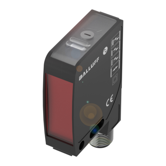
  • Seite 5: Anschlüsse

    Anschlüsse Anzeige- und Bedienelemente (Fortsetzung) Mehrfarbige LED (im Einsteller) LED blau: Lichttaster energetisch LED pink: Lichttaster mit Hintergrundausblendung LED weiß: Reflexions-Lichtschranke LED orange: Einweg-Lichtschranke Empfänger LED aus: Einweg-Lichtschranke Sender Blinkverhalten: Bild 2: Steckerbild, Anschluss-Schaltbild – LED blinkt rot (synchron zu LED 1 und LED 2): Lifetime Ende erreicht.
  • Seite 6: Einstellungen Am Sensor Im Sensorprinzip Reflexions-Lichtschranke

    Optoelektronische Sensoren Multifunktionssensor mit Zusatzfunktionen BOS 21M-UUI-RP30-S4 Einstellungen am Sensor im Sensorprinzip Prozessdaten Reflexions-Lichtschranke Ausgangsdaten Der Sensor überträgt 3 Byte Prozessdaten an den Master Standardeinstellung (M-Sequence TYPE_2_V). 1. Den Sensor und Reflektor auf die gewünschte Entfer- nung zum Objekt positionieren. Byte 0 2.
  • Seite 7: Werkseinstellung

    Prozessdaten (Fortsetzung) Werkseinstellung (Fortsetzung) Counter Reset Parameter Werks- Bemerkung einstellung Zählerstand auf Null zurücksetzen. Betriebsstundenzähler LED Off Operating Hours Sender und Objekterkennung inaktiv. Maintenance Der Sensor nimmt den folgenden Zustand an: Smart-Sensor-Funktionen Funktion Zustand BDC1 Pin 2 (SIO) hochohmig Pin 4 (SIO) hochohmig Zählerstand bleibt erhalten...
  • Seite 8 Optoelektronische Sensoren Multifunktionssensor mit Zusatzfunktionen BOS 21M-UUI-RP30-S4 Sensor-Funktionsprinzip Schaltmodus (Fortsetzung) Der Sensor unterstützt vier Sensor-Funktionsprinzipien. Zum Einlernen der Schaltpunkte SP1 und SP2 im IO-Link- Über den IO-Link-Parameter SensorPrinciple 0x00BB Betrieb können zwei statische Teach-In-Verfahren (Two kann zwischen Lichttaster energetisch, Lichttaster mit...
  • Seite 9 0x0002 (2) 0x00 (0) 0x44 (68) SP1 Two Value 0x003B 0x00 0x01 SP1 erfolg- Teach-In Teach TP2 (59) reich über- erfolg- nommen reich Teach State beendet = SP1 SUCCESS 0x07 Teach State Weiter zu = Error Schritt 3 www.balluff.com deutsch...
  • Seite 10 Optoelektronische Sensoren Multifunktionssensor mit Zusatzfunktionen BOS 21M-UUI-RP30-S4 Two Value Teach: Teach-In mit 2 Teach-Punkten Dynamic Teach: Dynamisches Teach-In (Fortsetzung) Prinzip Das dynamische Teach-In ermöglicht die Schaltpunktein- 7. Prüfen, ob SP1 erfolgreich eingelernt wurde: stellung, ohne den Prozess anzuhalten. Auslesen und Prüfen des Parameters Teach-In-Status Typische Anwendung: Schaltpunkteinstellung bei seitlich mit Index 0x003B.
  • Seite 11: Zählfunktion

    Hysterese einstellen Zählfunktion Die Hysterese (Parameter 0x003D) kann entsprechend der Im IO-Link-Betrieb kann über den Parameter 0x00B6 die Anwendung vergrößert oder verkleinert werden. Der Zählfunktion parametriert werden. Es wird ein Vorwahlwert Wertebereich für die Hysterese entspricht keiner Prozen- vorgegeben (Limit). Der Zähler beginnt mit dem Zähler- tangabe.
  • Seite 12: Frequenzwächter

    Optoelektronische Sensoren Multifunktionssensor mit Zusatzfunktionen BOS 21M-UUI-RP30-S4 Zählfunktion (Fortsetzung) Frequenzwächter (Fortsetzung) Counter Mode AUTO (automatischer Reset) Imp/min Überfrequenz Nach Erreichen des Vorwahlwerts beginnt der Zähler mit too high Einschaltwert = UpperLimitHigh der nächsten Objektdetektion automatisch wieder von Ausschaltwert = UpperLimitLow vorne mit dem Zählwert 1 und der Zählerausgang wird automatisch zurückgesetzt.
  • Seite 13 Datenhaltung und lokale Parametrierung Stresslevel Info Die Datenhaltung (Parameter 0x000C, Bit 1) dient zum Der Parameter 0x0500 Stresslevel liefert Informationen einfachen Sensortausch. Die Konfiguration eines Sensors über die elektrische und thermische Belastung des Sen- wird bei aktivierter Datenhaltung automatisch bei einem sors.
  • Seite 14: Io-Link-Interface

    Optoelektronische Sensoren Multifunktionssensor mit Zusatzfunktionen BOS 21M-UUI-RP30-S4 IO-Link-Interface Identifikations-Parameter Index Name Subindex Datenformat Zugriff Inhalt (dez) (dez) (Länge) 0x0010 Vendor Name 0x00 (0) StringT (7 Byte) Balluff (16) 0x0011 Vendor Text 0x00 (0) StringT (15 Byte) www.balluff.com (17) 0x0012 Product Name 0x00 (0) StringT (19 Byte)
  • Seite 15 IO-Link-Interface (Fortsetzung) Device-spezifische Parameter Index Name Subindex Name Daten - Zugriff Wertebereich Bemerkung (dez) (dez) format Sensorprinzip Auswahl 0x00BB Sensor 0x00 (0) UINT8 0x00 (0) = Lichttaster energetisch (187) Principle 0x01 (1) = Lichttaster mit Hintergrundausblendung 0x02 (2) = Reflexions-Licht- schranke 0x03 (3) = Einweglichtschranke Sender...
  • Seite 16 Optoelektronische Sensoren Multifunktionssensor mit Zusatzfunktionen BOS 21M-UUI-RP30-S4 IO-Link-Interface (Fortsetzung) Zeitfunktionen 0x00B8 Time delay 0x01 (1) Delay Function UINT8 0x00 (0) = Delay (184) function Mode 0x01 (1) = One shot 0x02 (2) Delay Time 1 UINT16 0x0000…0xFFFF (0…65535) Millisekunden (Pin 4)
  • Seite 17 IO-Link-Interface (Fortsetzung) Diagnose Parameter Index Name Subindex Name Datenformat Zugriff Wertebereich Bemerkung (dez) (dez) 0x0024 Device 0x00 (0) UINT8 0x00 (0) = Device OK (36) Status 0x01 (1) =  Maintenance-Required 0x02 (2) = Out-of-Specification 0x03 (3) = Functional- Nicht verwendet Check 0x04 (4) = Failure 0x0025 Detailed 0x00 (0)
  • Seite 18 Optoelektronische Sensoren Multifunktionssensor mit Zusatzfunktionen BOS 21M-UUI-RP30-S4 IO-Link-Interface (Fortsetzung) Events Event Bedeutung Mode Device Status Bemerkung Code 0x4210 Excess appears/ Warning Out-of-Specification Temperature disappears 0x5000 Device Hardware appears/ Error Failure Fault – Exchange disappears device 0x7710 Short Circuit appears/ Warning...
  • Seite 19 IO-Link-Interface (Fortsetzung) Systemkommandos Index Name Daten- Zugriff Wertebereich Bemerkung (dez) format 0x0002 System UINT8 0x01 (1) = Blockpara- Start Parameter Upload Command ParamUploadStart metrierung 0x02 (2) = Stopp Parameter Upload ParamUploadEnd 0x03 (3) = Start Parameter Download ParamDownloadStart 0x04 (4) = Stopp Parameter Download ParamDownloadEnd 0x05 (5) =...
  • Seite 20: Beschreibung

    Optoelektronische Sensoren Multifunktionssensor mit Zusatzfunktionen BOS 21M-UUI-RP30-S4 IO-Link-Interface (Fortsetzung) Error Codes Error Code Beschreibung 0x8011 Index not available 0x8012 Subindex not available 0x8020 Service temporarily not available 0x8021 Service temporarily not available – Local control 0x8022 Service temporarily not available – Device control...
  • Seite 21: Fehleranzeige

    Fehleranzeige Fehler Anzeige LEDs (blinkend) Priorität Anzeige Ausgänge Lifetime Gefahr (Rot) LED Grün Aktiv LED Gelb LED Mehrfarbig Defekt/Datenverlust LED Grün Aus (hochohmig) LED Gelb LED Mehrfarbig Kurzschluss am LED Grün Ausgang Q1 pulst bis Fehler Digitalausgang Q1 behoben LED Gelb LED Mehrfarbig Kurzschluss am LED Grün...
  • Seite 22 Optoelektronische Sensoren Multifunktionssensor mit Zusatzfunktionen BOS 21M-UUI-RP30-S4 Technische Daten Optisch allgemein Elektrisch Funktionsprinzip Betriebsspannung U 10…30 V DC – Lichttaster energetisch Bemessungsbetriebsspannung U 24 V DC – Lichttaster mit Hintergrundausblendung Restwelligkeit (% von U ≤ 10 % – Reflexions-Lichtschranke – Einweg-Lichtschranke Sender oder Empfänger Leerlaufstrom I bei U ≤ 20 mA...
  • Seite 23: Lichttaster Energetisch

    Technische Daten Lichttaster mit Hintergrundausblendung Lichttaster energetisch 90 % Rem. 20 % Rem. Schaltabstand in mm Schaltabstand in mm Bild 14: Schalthysterese Bild 18: Funktionsreserve Reflexions-Lichtschranke 90 % / 90 % 90 % / 20 % Schaltabstand in mm typ. max. Reichweite Bild 15: Schaltabstandsabweichung Abstand Reflektor in m Bild 19: Funktionsreserve Einweg-Lichtschranke...
  • Seite 24 US Service Center CN Service Center Germany Germany China Balluff GmbH Balluff GmbH Balluff Inc. Balluff (Shanghai) trading Co., ltd. Schurwaldstrasse 9 Schurwaldstrasse 9 8125 Holton Drive Room 1006, Pujian Rd. 145. 73765 Neuhausen a.d.F. 73765 Neuhausen a.d.F. Florence, KY 41042 Shanghai, 200127, P.R.
  • Seite 25 BOS 21M-UUI-RP30-S4 User’s guide english...
  • Seite 26 In our EMC laboratory, which is accredited by DATech for BOS 21-HW-1, BOS 21-HW-2 testing electromagnetic compatibility, evidence has been Mounting bracket, 2 axes adjustable, steel provided that the Balluff products satisfy the EMC requirements of IEC 60947-5-2. BOS 21-HW-4 Mounting bracket, 1 axis adjustable, steel...
  • Seite 27 Connections Display and operating elements (continued) Multi-color LED (in setter) LED blue: Diffuse energetic sensor LED pink: Diffuse sensor with background suppression LED white: Retro-reflective LED orange: Through-beam receiver LED off: Through-beam emitter Flashing: Fig. 2: Pinouts, connection diagram – LED flashes red (synchronous with LED 1 and LED 2): Lifetime end reached.
  • Seite 28: Settings On The Sensor In The Sensor Principle Retro-Reflective

    Photoelectric Sensors Multi-function sensor with additional functions BOS 21M-UUI-RP30-S4 Settings on the sensor in the sensor principle Process data Retro-reflective Output data The sensor sends 3 bytes of process data to the master Standard setting (M-Sequence TYPE_2_V). 1. Position the sensor and reflector to the desired distance from the object.
  • Seite 29: Factory Setting

    Process data (continued) Factory default setting (continued) Counter Reset Parameters Factory Comment setting Reset counter value to zero. Operating hours counter LED Off Operating hours Emitter and object detection inactive. maintenance The sensor assumes the following state: Smart sensor functions Function Status BDC1...
  • Seite 30 Photoelectric Sensors Multi-function sensor with additional functions BOS 21M-UUI-RP30-S4 Sensor function principle Switch mode (continued) The sensor supports four sensor function principles. The Two static teach-in procedures (Two Value Teach and IO-Link parameter SensorPrinciple 0x00BB can be used Single Value Teach) or a dynamic teach-in procedure...
  • Seite 31 Sub- Value Meaning index index 0x003B 0x00 0x01 Teach-in 0x0002 (2) 0x00 (0) 0x44 (68) SP1 Two (59) success fully completed Value Teach applied success- Teach State fully = SP1 SUCCESS 0x07 Teach State Go to = Error Step 3 www.balluff.com english...
  • Seite 32 Photoelectric Sensors Multi-function sensor with additional functions BOS 21M-UUI-RP30-S4 Two Value Teach: Teach-In with 2 Teach points Dynamic Teach-In (continued) Principle Dynamic teach-in allows you to set the switchpoint without 7. Verify whether SP1 has been taught successfully: stopping the process.
  • Seite 33: Counter Function

    Setting hysteresis Counter function The hysteresis (Parameter 0x003D) can be extended or In IO-Link mode parameter 0x00B6 can be used to reduced according to the application. The value range for configure the counter function. A preselected value is hysteresis is not expressed in percent. The value range is specified (Limit).
  • Seite 34: Operating Hours Counter

    Photoelectric Sensors Multi-function sensor with additional functions BOS 21M-UUI-RP30-S4 Counter function (continued) Frequency monitor (continued) Counter Mode AUTO (automatic Reset) Imp/min Over-frequency After the preselected value has been reached the counter too high Switch-on value = UpperLimitHigh starts counting at counter value 1 with the next detection of an object and the counter output is reset automatically.
  • Seite 35 Data storage and local parameter setting Stresslevel Info Data storage (parameter 0x000C, Bit 1) is used for ease of The parameter 0x0500 Stresslevel provides information sensor replacement. When data storage is enabled the about the electrical and thermal load on the sensor. This configuration of a sensor is automatically sent to the new enables the operator to check the ambient conditions and sensor when sensors are replaced.
  • Seite 36: Identification Parameters

    Photoelectric Sensors Multi-function sensor with additional functions BOS 21M-UUI-RP30-S4 IO-Link interface Identification parameters Index Name Subindex Data format Access Contents (dec) (dec.) (length) 0x0010 Vendor Name 0x00 (0) StringT (7 bytes) Balluff (16) 0x0011 Vendor text 0x00 (0) StringT (15 bytes) www.balluff.com...
  • Seite 37 IO-Link interface (continued) Device-specific parameters Index Name Sub- Name Data Access Value range Comment (dec) index format (dec.) Sensor principle selection 0x00BB Sensor 0x00 (0) UINT8 0x00 (0) = Diffuse energetic (187) Principle sensor 0x01 (1) = Diffuse sensor with background suppression 0x02 (2) = Retro-reflective 0x03 (3) = Through-beam emitter...
  • Seite 38 Photoelectric Sensors Multi-function sensor with additional functions BOS 21M-UUI-RP30-S4 IO-Link interface (continued) Time functions 0x00B8 Time delay 0x01 (1) Delay Function UINT8 0x00 (0) = Delay (184) function Mode 0x01 (1) = One shot 0x02 (2) Delay Time 1 UINT16 0x0000…0xFFFF (0…65535) Milliseconds (Pin 4) (On delay)
  • Seite 39 IO-Link interface (continued) Diagnosis parameters Index Name Sub- Name Data format Access Value range Comment (dec.) index (dec.) 0x0024 Device status 0x00 (0) UINT8 0x00 (0) = Device OK (36) 0x01 (1) = Maintenance- Required 0x02 (2) = Out-of- Specification 0x03 (3) = Functional- Not used Check 0x04 (4) = Failure...
  • Seite 40 Photoelectric Sensors Multi-function sensor with additional functions BOS 21M-UUI-RP30-S4 IO-Link interface (continued) Events Event code Meaning Mode Type Device status Comment 0x4210 Excess appears/ Warning Out-of-Specification Temperature disappears 0x5000 Device Hardware appears/ Error Failure Fault – Exchange disappears device 0x7710...
  • Seite 41 IO-Link interface (continued) System commands Index Name Data Access Value range Comment (dec.) format 0x0002 System UINT8 0x01 (1) = Block Start Parameter Upload Command ParamUploadStart parameterization 0x02 (2) = Stop Parameter Upload ParamUploadEnd 0x03 (3) = Start Parameter Download ParamDownloadStart 0x04 (4) = Stop Parameter Download...
  • Seite 42 Photoelectric Sensors Multi-function sensor with additional functions BOS 21M-UUI-RP30-S4 IO-Link interface (continued) Error codes Error Code Description 0x8011 Index not available 0x8012 Subindex not available 0x8020 Service temporarily not available 0x8021 Service temporarily not available – Local control 0x8022 Service temporarily not available – Device control...
  • Seite 43 Error display Error Display LEDs (flashing) Priority display Outputs Lifetime danger (red) LED green Active LED yellow LED multi-color Defective/data loss LED green Off (high-impedance) LED yellow LED multi-color Short circuit on LED green Output Q1 pulses until error digital output Q1 cleared LED yellow LED multi-color...
  • Seite 44 Photoelectric Sensors Multi-function sensor with additional functions BOS 21M-UUI-RP30-S4 Technical data General optics Electrical Functional principle Supply voltage U 10…30 V DC – Diffuse energetic sensor Rated operating voltage U 24 V DC – Diffuse sensor with background suppression Ripple (% of U ≤ 10% –...
  • Seite 45: Technical Data

    Technical data Diffuse sensor with background suppression Diffuse energetic sensor 90 % rem. 20 % rem. Switching distance in mm Switching distance in mm Fig. 14: Switching hysteresis Fig. 18: Excess Gain Retro-reflective 90 % / 90 % 90 % / 20 % Switching distance in mm Typ.
  • Seite 46 US Service Center CN Service Center Germany Germany China Balluff GmbH Balluff GmbH Balluff Inc. Balluff (Shanghai) trading Co., ltd. Schurwaldstrasse 9 Schurwaldstrasse 9 8125 Holton Drive Room 1006, Pujian Rd. 145. 73765 Neuhausen a.d.F. 73765 Neuhausen a.d.F. Florence, KY 41042 Shanghai, 200127, P.R.
  • Seite 47 BOS 21M-UUI-RP30-S4 Notice d’utilisation français...
  • Seite 48: Informations Produit

    Au sein de notre laboratoire CEM, accrédité par l’organisme DATech pour les contrôles de la compatibilité Accessoires de montage électromagnétique, nous avons démontré que les produits Balluff répondent aux exigences CEM de la norme BOS 21-HW-1, BOS 21-HW-2 CEI 60947-5-2. Equerre de montage, 2 axes réglables, matériau acier...
  • Seite 49 Connexions Eléments d’affichage et de commande (suite) LED multicolore (dans le dispositif de réglage) LED bleue : détecteur optique énergétique LED rose : détecteur optique avec suppression d’arrière plan LED blanche : barrage optique à réflexion LED orange : barrage optique unidirectionnel, récepteur LED éteinte : barrage optique unidirectionnel, émetteur Comportement de clignotement : Fig.
  • Seite 50 Capteurs optoélectroniques Capteur multifonction avec fonctions additionnelles BOS 21M-UUI-RP30-S4 Réglages sur le capteur selon le principe de capteur Données de processus Barrage optique à réflexion Données de sortie Le capteur transmet 3 octets de données de processus au Réglage standard module Master (M-Sequence TYPE_2_V).
  • Seite 51 Données de processus (suite) Réglage usine (suite) Counter Reset Paramètre Réglage Remarque d’usine Remise à zéro de la valeur du compteur. Compteur d’heures de service LED Off Operating Hours Emetteur et détection d’objets inactifs. Maintenance Le capteur adopte l’état suivant : Fonctions Smart Sensor Fonction Etat...
  • Seite 52 Capteurs optoélectroniques Capteur multifonction avec fonctions additionnelles BOS 21M-UUI-RP30-S4 Principe de fonctionnement du capteur Mode de commutation (Suite) Le capteur offre quatre principes de fonctionnement. Par le Pour l’apprentissage des points d’action SP1 et SP2 en biais du paramètre IO-Link SensorPrinciple 0x00BB, il est mode IO-Link, il est possible d’utiliser deux méthodes...
  • Seite 53 SP1 validé Apprentis- Accès Index Sub- Valeur Signification (59) avec succès sage index Teach State terminé 0x0002 (2) 0x00 (0) 0x44 (68) SP1 Two Value = SP1 avec Teach TP2 SUCCESS succès 0x07 Teach State Continuer = Error avec l’étape 3 www.balluff.com français...
  • Seite 54 Capteurs optoélectroniques Capteur multifonction avec fonctions additionnelles BOS 21M-UUI-RP30-S4 Two Value Teach : apprentissage avec 2 points Dynamic Teach : apprentissage dynamique (Suite) Principe L’apprentissage dynamique permet le réglage du point 7. Vérifier si le point SP1 a été appris avec succès : d’action sans arrêter le processus.
  • Seite 55: Régler L'hystérésis

    Régler l’hystérésis Fonction de comptage L’hystérésis (paramètre 0x003D) peut être élargie ou En mode IO-Link, la fonction de comptage peut être agrandie selon l’application. La plage de valeurs pour paramétrée par le biais du paramètre 0x00B6. Une valeur l’hystérésis ne correspond pas à un pourcentage. La plage de présélection (Limit) est définie.
  • Seite 56 Capteurs optoélectroniques Capteur multifonction avec fonctions additionnelles BOS 21M-UUI-RP30-S4 Fonction de comptage (suite) Contrôleur de fréquence (Suite) Counter Mode AUTO (Reset automatique) Imp/min fréquence trop haute Après avoir atteint la valeur de présélection, le compteur too high Valeur d’enclenchement = UpperLimitHigh recommence automatiquement lors de la prochaine Valeur de réinitialisation = UpperLimitLow...
  • Seite 57 Stockage des données et paramétrage local Infos Stresslevel Le stockage des données (paramètre 0x000C, bit 1) facilite Le paramètre 0x0500 Stresslevel fournit des informations le remplacement des capteurs. En cas de stockage des sur la charge électrique et thermique du capteur. données activé, la configuration d’un capteur est transmise L’exploitant est ainsi en mesure de contrôler les conditions automatiquement au nouveau capteur en cas de...
  • Seite 58 Capteurs optoélectroniques Capteur multifonction avec fonctions additionnelles BOS 21M-UUI-RP30-S4 Interface IO-Link Paramètre d’identification Index Subindex Format de données Accès Contenu (déc.) (Dec) (longueur) 0x0010 Vendor Name 0x00 (0) StringT (7 octets) Balluff (16) 0x0011 Vendor Text 0x00 (0) StringT (15 octets) www.balluff.com...
  • Seite 59 Interface IO-Link (suite) Paramètres spécifiques à l’appareil Index Subindex Format Accès Plage de valeurs Remarque (déc.) (Dec) données Choix du principe du capteur 0x00BB Sensor 0x00 (0) UINT8 0x00 (0) = Détecteur optique (187) Principle énergétique 0x01 (1) = Détecteur optique avec suppression d’arrière plan 0x02 (2) = Barrage optique à...
  • Seite 60 Capteurs optoélectroniques Capteur multifonction avec fonctions additionnelles BOS 21M-UUI-RP30-S4 Interface IO-Link (suite) Fonctions temps 0x00B8 Time delay 0x01 (1) Delay Function UINT8 0x00 (0) = Delay (184) function Mode 0x01 (1) = One shot 0x02 (2) Delay Time 1 UINT16 0x0000…0xFFFF (0…65535) Millisecondes (Broche 4) (On delay)
  • Seite 61 Interface IO-Link (suite) Paramètre de diagnostic Index Subindex Format de Accès Plage de valeurs Remarque (Dec) (Dec) données 0x0024 Device Status 0x00 (0) UINT8 0x00 (0) = Device OK (36) 0x01 (1) =  Maintenance-Required 0x02 (2) = Out-of-Specification 0x03 (3) = Functional- Inutilisé Check 0x04 (4) = Failure 0x0025 Detailed Device...
  • Seite 62 Capteurs optoélectroniques Capteur multifonction avec fonctions additionnelles BOS 21M-UUI-RP30-S4 Interface IO-Link (suite) Events Event Signification Mode Type Device Status Remarque Code 0x4210 Excess appears/ Warning Out-of-Specification Temperature disappears 0x5000 Device Hardware appears/ Error Failure Fault – Exchange disappears device 0x7710...
  • Seite 63 Interface IO-Link (suite) Commandes du système Index Format Accès Plage de valeurs Remarque (Dec) données 0x0002 System UINT8 0x01 (1) = Paramétrage de Démarrage du Parameter Upload Command ParamUploadStart blocs (Commande 0x02 (2) = Arrêt du Parameter Upload du système) ParamUploadEnd 0x03 (3) = Démarrage du Parameter...
  • Seite 64 Capteurs optoélectroniques Capteur multifonction avec fonctions additionnelles BOS 21M-UUI-RP30-S4 Interface IO-Link (suite) Codes d’erreur Code d’erreur Description 0x8011 Index not available 0x8012 Subindex not available 0x8020 Service temporarily not available 0x8021 Service temporarily not available – Local control 0x8022 Service temporarily not available – Device control...
  • Seite 65 Affichage d’erreur Erreur LED d’affichage (clignotantes) Affichage priorité Sorties Danger durée de vie (rouge) LED verte Actives LED jaune LED multicolore Défaut / perte de données LED verte Désactivées (haute impédance) LED jaune LED multicolore Court-circuit sur la LED verte La sortie Q1 pulse jusqu’à...
  • Seite 66: Caractéristiques Techniques

    Capteurs optoélectroniques Capteur multifonction avec fonctions additionnelles BOS 21M-UUI-RP30-S4 Caractéristiques techniques Optiques générales Electrique Principe de fonctionnement Tension d’emploi U 10…30 V DC – Détecteur optique énergétique Tension d’emploi nominale U 24 V CC – Détecteur optique avec suppression d’arrière plan Ondulation résiduelle (% de U ≤ 10 %...
  • Seite 67 Caractéristiques techniques Détecteur optique avec suppression d’arrière plan Détecteur optique énergétique Lum. réfl. 90 % Lum. réfl. 20 % Portée en mm Portée en mm Fig. 14 : Hystérésis de commutation Fig. 18 : Réserve de fonctionnement Barrage optique à réflexion 90 % / 90 % 90 % / 20 % Portée en mm...
  • Seite 68 US Service Center CN Service Center Germany Germany China Balluff GmbH Balluff GmbH Balluff Inc. Balluff (Shanghai) trading Co., ltd. Schurwaldstrasse 9 Schurwaldstrasse 9 8125 Holton Drive Room 1006, Pujian Rd. 145. 73765 Neuhausen a.d.F. 73765 Neuhausen a.d.F. Florence, KY 41042 Shanghai, 200127, P.R.
  • Seite 69 Notizen / to make notes / pour vos notes personelles www.balluff.com...
  • Seite 70 US Service Center CN Service Center Germany Germany China Balluff GmbH Balluff GmbH Balluff Inc. Balluff (Shanghai) trading Co., ltd. Schurwaldstrasse 9 Schurwaldstrasse 9 8125 Holton Drive Room 1006, Pujian Rd. 145. 73765 Neuhausen a.d.F. 73765 Neuhausen a.d.F. Florence, KY 41042 Shanghai, 200127, P.R.

Inhaltsverzeichnis