Ducati Performance ISTR-1011/00 Montageanleitung
ISTR - 1011 / 00
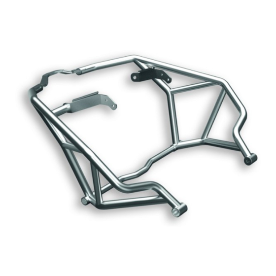
Kit barre laterali serbatoio
Tank side bar kit
- 96780861C
Simbologia
Per una lettura rapida e razionale sono stati impiegati simboli che
evidenziano situazioni di massima attenzione, consigli pratici o
semplici informazioni. Prestare molta attenzione al significato dei
simboli, in quanto la loro funzione è quella di non dovere ripete-
re concetti tecnici o avvertenze di sicurezza. Sono da considerare,
quindi, dei veri e propri "promemoria". Consultare questa pagina
ogni volta che sorgeranno dubbi sul loro significato.
Attenzione
La non osservanza delle istruzioni riportate può creare una situa-
zione di pericolo e causare gravi lesioni personali e anche la morte.
Importante
Indica la possibilità di arrecare danno al veicolo e/o ai suoi compo-
nenti se le istruzioni riportate non vengono eseguite.
Note
Fornisce utili informazioni sull'operazione in corso.
Riferimenti
I particolari evidenziati in grigio e riferimento numerico (Es.
rappresentano l'accessorio da installare e gli eventuali componenti
di montaggio forniti a kit.
I particolari con riferimento alfabetico (Es.
componenti originali presenti sul motoveicolo.
Tutte le indicazioni destro o sinistro si riferiscono al senso di marcia
del motociclo.
Avvertenze generali
Attenzione
Le operazioni riportate nelle pagine seguenti devono essere ese-
guite da un tecnico specializzato o da un'officina autorizzata Du-
cati.
Attenzione
Le operazioni riportate nelle pagine seguenti se non eseguite a re-
gola d'arte possono pregiudicare la sicurezza del pilota.
Note
Documentazione necessaria per eseguire il montaggio del Kit è il
Manuale Officina, relativo al modello di moto in vostro possesso.
Note
Nel caso fosse necessaria la sostituzione di un componente del kit
consultare la tavola ricambi allegata.
1
- 96780861C
1
A
) rappresentano i
Symbols
The symbols used in this manual are aimed at making reading di-
rect and easy. The symbols are used either to draw the reader's
attention on potentially hazardous conditions, or to give practical
advice or to supply general information. Pay the utmost attention
to these symbols as they are used to remind of technical principles
or safety measures which will not be repeated extensively. They
must therefore be considered as "reminders". Check with this page
in case of doubt about their meaning.
Warning
Failure to comply with these instructions may put you at risk and
lead to severe injury or death.
Important
It indicates the possibility of damaging the motorcycle and/or its
components if the instructions are not followed.
Notes
It supplies useful information about the operation in progress.
References
)
The parts highlighted in grey and with a reference number (e.g.
) represent the accessory to be installed and any assembly compo-
nents supplied with the kit.
The parts with alphabetic reference (e.g.
components present on the motorcycle.
All left and right indications are referred to the motorcycle direc-
tion of travel (forward riding position).
General notes
Warning
The operations listed in the following pages must be carried out by
a specialised technician or by a Ducati authorised service centre.
Warning
Carefully perform the operations on the following pages since they
might negatively affect rider safety.
Notes
The Workshop Manual of your motorcycle model is the documen-
tation required to assemble the Kit.
Notes
Should it be necessary to change any kit parts, please refer to the
attached spare part table.
Warning
Operating, servicing and maintaining a passenger vehicle or off-
highway motor vehicle can expose you to chemicals including en-
gine exhaust, carbon monoxide, phthalates, and lead, which are
known to the State of California to cause cancer and birth defects
or other reproductive harm. To minimize exposure, avoid breath-
ing exhaust, do not idle the engine except as necessary, service
your vehicle in a well-ventilated area and wear gloves or wash your
hands frequently when servicing your vehicle. For more informa-
tion go to www.P65Warnings.ca.gov/passenger-vehicle.
1
A
) represent the original
Inhaltsverzeichnis

Verwandte Anleitungen für Ducati Performance ISTR-1011/00


Inhaltszusammenfassung für Ducati Performance ISTR-1011/00
- Seite 1 Du- The operations listed in the following pages must be carried out by cati. a specialised technician or by a Ducati authorised service centre. Attenzione Warning Le operazioni riportate nelle pagine seguenti se non eseguite a re- Carefully perform the operations on the following pages since they gola d’arte possono pregiudicare la sicurezza del pilota.
- Seite 2 ISTR 1011 / 00 Importante Important I componenti del kit possono essere soggetti ad aggiornamenti; The parts of the kit can be updated; for information always up to consultare il DCS (Dealer Communication System) per avere infor- date, please refer to DCS (Dealer Communication System). mazioni sempre aggiornate.
- Seite 3 ISTR 1011 / 00 OPEN Smontaggio componenti originali Removing the original components Smontaggio sella Removing the seat Inserire la chiave (S) nella serratura sella e ruotarla in senso ora- Insert the key (S) into the seat lock and turn it clockwise until the rio fino a sentire lo scatto del gancio, come indicato in figura (Z1).
- Seite 4 ISTR 1011 / 00 Smontaggio convogliatori Conveyor disassembly Rimuovere la cover Hands free (A) tirandola verso l’alto e sgancian- Remove the Hands free cover (A) by pulling it upwards and releas- do i dentini (A1). Svitare le n.2 viti (B1) e rimuovere il convogliatore ing teeth (A1).
- Seite 5 ISTR 1011 / 00 Smontaggio ali laterali Side panel disassembly Operando sul lato destro del motoveicolo, svitare le n.2 viti speciali Working on motorcycle right hand side, loosen no.2 special screws (Z2) e la vite (Z1) di fissaggio dell’ala laterale destra (Z) alla cover (Z2) and screw (Z1) fastening RH side panel (Z) to RH tank cover serbatoio destra (D).
- Seite 6 ISTR 1011 / 00 Smontaggio cover laterale destra serbatoio Removing the tank RH side cover Operando sul lato destro del motoveicolo, svitare le n.3 viti (D1) con Working on motorcycle right hand side, loosen no.3 screws (D1) rondelle (D2), svitare le n.2 viti (D3) e le n.3 viti (D4). Rimuovere with washers (D2), loosen no.2 screws (D3) and no.3 screws (D4).
- Seite 7 ISTR 1011 / 00 Smontaggio cover laterale sinistra serbatoio Removing the tank LH side cover Operando sul lato sinistro del motoveicolo, svitare le n.3 viti (F1) Working on motorcycle left hand side, loosen no.3 screws (F1) with con rondelle (F2), svitare le n.2 viti (F3) e le n.3 viti (F4). Rimuovere washers (F2), loosen no.2 screws (F3) and no.3 screws (F4).
- Seite 8 ISTR 1011 / 00 Smontaggio cover centrale serbatoio Removing the central tank cover Svitare da entrambi i lati della cover serbatoio (G) le n.4 viti (G1) Loosen no.4 screws (G1) with washers (G2) on both sides of tank con rondelle (G2). Svitare le n.2 viti superiori (G3) con rondelle (G4). cover (G).
- Seite 9 ISTR 1011 / 00 Arretramento serbatoio Moving tank backward Operando sulla parte anteriore del serbatoio (E), chiudere i n.2 ru- Working on tank (E) front side, close no.2 taps (E3) rotating no.2 binetti (E3) ruotando in senso orario le n.2 ghiere (E4). Allentare le ring nuts (E4) clockwise.
- Seite 10 ISTR 1011 / 00...
- Seite 11 ISTR 1011 / 00 Operando sul lato destro del motoveicolo, svitare le n.2 viti (N1) e Working on motorcycle RH side, loosen no.2 screws (N1) and re- rimuovere il piastrino supporto serbatoio destro (N). Operando sul move RH tank support plate (N). Working on motorcycle LH side, lato sinistro del motoveicolo, svitare le n.2 viti (P1) e rimuovere il loosen no.2 screws (P1) and remove LH tank support plate (P).
- Seite 12 ISTR 1011 / 00 Smontaggio viti fissaggio radiatore acqua e staffe Removing water radiator fastening screws and en- paramotore gine protection brackets Note Notes Per comprendere meglio le restanti fasi di smontaggio, non viene To better understand the remaining steps for removal, the tank rappresentato il serbatoio precedentemente arretrato.
- Seite 13 ISTR 1011 / 00 Montaggio componenti kit Assembling the kit components Note Notes Per comprendere meglio alcune fasi di montaggio, non viene rap- To better understand some assembly steps, the tank is not shown. presentato il serbatoio. Important Importante Before assembling, check that all parts are clean and in good con- Verificare, prima del montaggio, che tutti i componenti risultino ditions.
- Seite 14 ISTR 1011 / 00 Per i possessori di motoveicoli dove la staffa (T2) di supporto radia- For the owners of motorcycles where bracket (T2) supporting wa- tore acqua è come quella rappresentata in figura (Y), occorre pro- ter radiator is as the one shown in figure (Y), proceed as follows. cedere come segue.
- Seite 15 ISTR 1011 / 00 Operando sul lato destro del motoveicolo, avvolgere in tubo di Working on motorcycle RH side, wrap oil cooler (T) breather tube sfiato (T1) del radiatore (T) con una porzione di guaina a spirale (T1) with a portion of spiral guard (19), as shown in the figure. (19), come mostrato in figura.
- Seite 16 ISTR 1011 / 00 50Nm ± 10% 50Nm ± 10%...
- Seite 17 ISTR 1011 / 00 Applicare grasso grafitato su stelo e sotto testa della vite speciale Apply graphite grease on the stem and underhead of special screw (4). Operando sul lato sinistro del motoveicolo, impuntare la vite (4). Working on motorcycle left hand side, start special screw (4) speciale (4) sulla staffa paramotore (S1).
- Seite 18 ISTR 1011 / 00 10 Nm ± 10% 25 Nm ± 10% Operando sull’anteriore del motoveicolo, portare in appoggio il Working on the front of the motorcycle, bring rubber block (12) tampone (12) al pannello inferiore (J), come mostrato in figura (V1). against lower panel (J), as shown in figure (V1).
- Seite 19 ISTR 1011 / 00 Dopo il serraggio delle n.2 viti (13) o (14), rimuovere le protezioni After tightening no.2 screws (13) or (14), remove side protections laterali (1) e (2) eseguendo la procedura inversa descritta in prece- (1) and (2) following the previously-described procedure in reverse denza.
- Seite 20 ISTR 1011 / 00 10 Nm ± 10% 10 Nm ± 10% 5 Nm ± 10% 5 Nm ± 10%...
- Seite 21 ISTR 1011 / 00 Rimontaggio serbatoio Refitting the tank Riposizionare il serbatoio (E) sul telaio. Assicurarsi che siano ancora Reposition the tank (E) on the frame. Make sure that the no.4 rub- presenti sul serbatoio (E) i n.4 tamponi (E6) e i n.2 distanziali (E7). ber blocks (E6) and the no.2 spacers (E7) are still present on tank Impuntare le n.2 viti (E5) e serrarle alla coppia indicata.
- Seite 22 ISTR 1011 / 00 Operando sulla parte anteriore del serbatoio (E), ricollegare il tubo Working on tank (E) front side, reconnect pipe (M) to the 2 taps (M) ai n.2 rubinetti (E3). Serrare le n.2 fascette (M1). Aprire com- (E3). Tighten no.2 clamps (M1). Open the 2 taps (E3) completely by pletamente i n.2 rubinetti (E3) ruotando in senso antiorario le n.2 rotating the 2 ring nuts (E4) counter clockwise.
- Seite 23 ISTR 1011 / 00 4 Nm ± 10% 4 Nm ± 10% 4 Nm ± 10% 4 Nm ± 10% 5 Nm ± 10% 5 Nm ± 10% Rimontaggio cover serbatoio Fuel tank cover reassembly Applicare lubrificante per gomma sulle superfici di contatto del- Apply lubricant on gasket surfaces (E9) in contact with tank plug.
- Seite 24 ISTR 1011 / 00 4 Nm ± 10% 2 Nm ± 10% 2 Nm ± 10% 4 Nm ± 10% 2 Nm ± 10% 4 Nm ± 10% 2 Nm ± 10% Rimontaggio cover laterali serbatoio Refitting the tank side covers Inserire le n.3 rondelle (D2) sulle n.3 viti (D1).
- Seite 25 ISTR 1011 / 00 6 Nm ± 10% 6 Nm ± 10% Rimontaggio ali laterali Side panel reassembly Operando sul lato destro del motoveicolo, posizionare l’ala laterale Working on motorcycle RH side, position RH side panel (Z) on RH destra (Z) sulla cover serbatoio destra (D), impuntare la vite (Z1) e tank cover (D), start screw (Z1) and no.2 special screws (Z2).
- Seite 26 ISTR 1011 / 00 2 Nm ± 10% 2 Nm ± 10% Rimontaggio convogliatori Conveyor reassembly Montare il convogliatore laterale destro (B) portandolo in posizio- Assemble RH side conveyor (B) bringing it to the correct position ne e traslandolo prima in avanti e poi indietro, in modo che l’aletta and moving it forward and backward so that tab (B2) fits in slot (X1) (B2) si inserisca nell’asola (X1) ed i cavallotti (B3) nei denti (X2).
- Seite 27 ISTR 1011 / 00 10 Nm ± 10% 10 Nm ± 10% Rimontaggio sella pilota Rider seat reassembly Posizionare la parte anteriore della sella pilota (S2), provvista di Position the front side of the rider seat (S2), provided with slots asole (S6), nelle guide (S3).
- Seite 28 ISTR 1011 / 00 Rimontaggio sella passeggero Passenger seat reassembly Lubrificare la sede (Y1) del perno (S7) con SHELL GADUS S2 V220 Lubricate the seat (Y1) of pin (S7) with SHELL GADUS S2 V220 AD 2. Posizionare la sella passeggero (S1) e inserire la linguetta AD 2.
- Seite 29 ISTR 1011 / 00 Montaggio protezioni laterali Side protection assembly Inserire la rosetta (18) sulla vite (8). Applicare grasso SHELL GA- Fit washer (18) on screw (8). Smear the thread of screw (8) with DUS S2 V100 3 sul filetto della vite (8). Inserire la vite (8) con roset- grease SHELL GADUS S2 V100 3.
- Seite 30 ISTR 1011 / 00...
- Seite 31 ISTR 1011 / 00 Inserire la parte anteriore della protezione laterale destra (2) sulla Fit RH side protection (2) front side on the projection of no.2 sporgenza delle n.2 viti quadre (15) e il foro centrale sull’estremità square head screws (15) and central hole on rubber block projection del tampone (12A), come mostrato in figura (V1).
- Seite 32 ISTR 1011 / 00 40 Nm ± 10% 40 Nm ± 10% 40 Nm ± 10% 10 Nm ± 10% 40 Nm ± 10% Serrare i n.2 dadi (7), le n.4 viti (8) e le n.2 viti (11) alla coppia indica- Tighten no.2 nuts (7), no.4 screws (8) and no.2 screws (11) to the ta seguendo la sequenza indicata in figura.
-
Seite 33: Avertissements Généraux
Ducati. Die auf den folgenden Seiten beschriebenen Arbeitsmaßnahmen Attention müssen von einem Fachtechniker oder einer Ducati Vertragswerk- Les opérations indiquées dans les pages suivantes, au cas où elles statt ausgeführt werden. ne seraient pas effectuées selon les règles de l'art pourraient com- Achtung promettre la sécurité... - Seite 34 ISTR 1011 / 00 Important Wichtig Les composants du kit peuvent être soumis à des mises à jour ; Die Bestandteile des Kits können Aktualisierungen unterliegen. veuillez consulter le DCS (Dealer Communication System) pour des Lesen Sie stets die Angaben im DCS (Dealer Communication Sys- informations toujours actualisées.
-
Seite 35: Abnahme Der Original-Bestandteile
ISTR 1011 / 00 OPEN Dépose des composants d'origine Abnahme der Original-Bestandteile Dépose de la selle Abnahme der Sitzbank Insérer la clé (S) dans la serrure de la selle et la tourner dans le sens Den Schlüssel (S) in das Sitzbankschloss einstecken und so lange des aiguilles d'une montre jusqu'à... - Seite 36 ISTR 1011 / 00 Dépose des déflecteurs Abnahme der Luftleitkanäle Déposer le cache Hands Free (A) en le tirant vers le haut et en Die Abdeckung des Hands Free (A) nach oben ziehen und nach décrochant les ergots (A1). Desserrer les 2 vis (B1) et déposer le dem Lösen der Zähne (A1) entfernen.
- Seite 37 ISTR 1011 / 00 Dépose des ailes latérales Abnahme der seitlichen Flügelteile En intervenant du côté droit du motocycle, desserrer les 2 vis spé- An der rechten Seite des Motorrads die 2 Spezialschrauben (Z2) ciales (Z2) et la vis (Z1) de fixation de l'aile latérale droite (Z) au und die Schraube (Z1) der Befestigung der rechten Seitenplatte cache réservoir droit (D).
- Seite 38 ISTR 1011 / 00 Dépose du cache latéral droit réservoir Abnahme der seitlichen rechten Tankabdeckung En intervenant du côté droit du motocycle, desserrer les 3 vis (D1) An der rechten Seite des Motorrads die 3 Schrauben (D1) mit Un- avec rondelles (D2), desserrer les 2 vis (D3) et les 3 vis (D4). Dépo- terlegscheiben (D2), dann die 2 Schrauben (D3) und die 3 Schrau- ser le cache réservoir droit (D) du réservoir (E) en décrochant le ben (D4) lösen.
- Seite 39 ISTR 1011 / 00 Dépose du cache latéral gauche réservoir Abnahme der seitlichen linken Tankabdeckung En intervenant du côté gauche du motocycle, desserrer les 3 vis An der linken Seite des Motorrads die 3 Schrauben (F1) mit Unter- (F1) avec rondelles (F2), desserrer les 2 vis (F3) et les 3 vis (F4). Dé- legscheiben (F2), dann die 2 Schrauben (F3) und die 3 Schrauben poser le cache réservoir gauche (F) du réservoir (E) en décrochant (F4) lösen.
- Seite 40 ISTR 1011 / 00 Dépose du cache central réservoir Abnahme der mittleren Tankabdeckung Desserrer des deux côtés du cache réservoir (G) les 4 vis (G1) avec Die 4 Schauben (G1) mit Unterlegscheiben (G2) an beiden Seiten rondelles (G2). Desserrer les 2 vis supérieures (G3) avec rondelles der Tankabdeckung (G) lösen.
- Seite 41 ISTR 1011 / 00 Recul réservoir Zurückziehen des Tanks En agissant sur la partie avant du réservoir (E), fermer les 2 robi- An der Front des Tanks (E) die 2 Hähne (E3) schließen, dazu die 2 nets (E3) en tournant dans le sens des aiguilles d'une montre les 2 Nutmuttern (E4) im Uhrzeigersinn drehen.
- Seite 42 ISTR 1011 / 00...
- Seite 43 ISTR 1011 / 00 En agissant du côté droit du motocycle, desserrer les 2 vis (N1) et An der rechten Seite des Motorrads die 2 Schrauben (N1) lösen, déposer la plaquette support réservoir droit (N). En agissant du dann das rechte Halteplättchen des Tanks (N) entfernen. An der côté...
- Seite 44 ISTR 1011 / 00 Dépose des vis de fixation du radiateur eau et des Lösen der Befestigungsschrauben des Wasserküh- brides pare-moteur lers und Abnahme der Motorschutzbügel Remarques Hinweise Afin de mieux comprendre les phases de dépose restantes, le ré- Zum besseren Verständnis der verbleibenden Abnahmeschritte servoir précédemment reculé...
-
Seite 45: Montage Der Kit-Bestandteile
ISTR 1011 / 00 Pose des composants kit Montage der Kit-Bestandteile Remarques Hinweise Afin de mieux comprendre certaines phases de pose, le réservoir Zum besseren Verständnis einiger Montageschritte wird der Tank n'est pas représenté. nicht dargestellt. Important Wichtig Avant la pose, vérifier que tous les composants sont propres et en Vor der Montage überprüfen, dass alle Bestandteile sauber sind bon état. - Seite 46 ISTR 1011 / 00 Les propriétaires de motocycles où la bride (T2) de support radia- An den Motorrädern, die einen Stützbügel (T2) des Wasserküh- teur eau résulte comme celle dans la figure (Y) sont priés de pro- lers wie auf Abbildung (Y) dargestellt, aufweisen, muss wie folgt céder comme indiqué...
- Seite 47 ISTR 1011 / 00 En agissant du côté droit du motocycle, enrouler une durite reni- An der rechten Seite des Motorrads arbeitend, den Entlüftungs- flard (T1) du radiateur (T) avec une partie de gaine à spirale (19), schlauch (T1) des Ölkühlers (T), wie abgebildet, mit einem Teil der comme la figure le montre.
- Seite 48 ISTR 1011 / 00 50Nm ± 10% 50Nm ± 10%...
- Seite 49 ISTR 1011 / 00 Appliquer de la graisse graphitée sur la tige et le dessous de tête Graphitfett auf das Schaft und unter den Kopf der Spezialschrau- de la vis spéciale (4). En agissant du côté gauche du motocycle, be (4) auftragen. An der linken Seite des Motorrads nun die Spe- présenter la vis spéciale (4) sur la bride pare-moteur (S1).
- Seite 50 ISTR 1011 / 00 10 Nm ± 10% 25 Nm ± 10% En agissant du côté avant du motocycle, présenter le tampon (12) An der Motorradfront nun den Stopfen (12) an der unteren Platte sur le panneau inférieur (J), comme la figure (V1) le montre. (J) zum Anliegen bringen;...
- Seite 51 ISTR 1011 / 00 Après le serrage des 2 vis (13) ou (14) déposer les protections laté- Nach dem Anzug der 2 Schrauben (13) oder (14), die seitlichen rales (1) ou (2) en suivant dans l'ordre inverse la procédure décrite Schutzplatten (1) und (2) abnehmen;...
- Seite 52 ISTR 1011 / 00 10 Nm ± 10% 10 Nm ± 10% 5 Nm ± 10% 5 Nm ± 10%...
- Seite 53 ISTR 1011 / 00 Repose du réservoir Montage des Tanks Repositionner le réservoir (E) sur le cadre. S'assurer de la présence Den Tank (E) erneut am Rahmen anordnen. Sicherstellen, dass die des 4 tampons (E6) et des 2 entretoises (E7) sur le réservoir (E). 4 Stopfen (E6) und die 2 Distanzstücke (E7) noch am Tank (E) vor- Présenter les 2 vis (E5) et les serrer au couple de serrage prescrit.
- Seite 54 ISTR 1011 / 00 En agissant sur la partie avant du réservoir (E), brancher de nou- An der Front des Tanks (E) nun den Schlauch (M) an den 2 Hähnen veau le tuyau (M) aux 2 robinets (E3). Serrer les 2 colliers (M1). (E3) anschließen.
- Seite 55 ISTR 1011 / 00 4 Nm ± 10% 4 Nm ± 10% 4 Nm ± 10% 4 Nm ± 10% 5 Nm ± 10% 5 Nm ± 10% Repose du cache réservoir Montage der Tankabdeckung Appliquer du lubrifiant pour caoutchouc sur les surfaces de contact Schmiermittel für Gummielemente auf die Kontaktfläche der du joint (E9) avec le bouchon de réservoir.
- Seite 56 ISTR 1011 / 00 4 Nm ± 10% 2 Nm ± 10% 2 Nm ± 10% 4 Nm ± 10% 2 Nm ± 10% 4 Nm ± 10% 2 Nm ± 10% Repose des caches latéraux réservoir Montage der seitlichen Tankabdeckungen Insérer les 3 rondelles (D2) sur les 3 vis (D1).
- Seite 57 ISTR 1011 / 00 6 Nm ± 10% 6 Nm ± 10% Repose des ailes latérales Montage der seitlichen Flügelteile En agissant du côté droit du motocycle, positionner l'aile latérale An der rechten Seite des Motorrads die rechte Seitenplatte (Z) droite (Z) sur le cache réservoir droit (D), présenter la vis (Z1) et les auf der rechten Tankabdeckung (D) anordnen, dazu die Schraube 2 vis spéciales (Z2).
- Seite 58 ISTR 1011 / 00 2 Nm ± 10% 2 Nm ± 10% Repose des déflecteurs Montage der Luftleitkanäle Poser le déflecteur latéral droit (B) en le portant dans la bonne po- Den rechten seitlichen Luftkanal (B) montieren, in seine Posi- sition et en le déplaçant avant tout en avant et ensuite en arrière, tion bringen, dann erst nach vorne, dann nach hinten verschie- afin que la patte (B2) s’insère dans la fente (X1) et les étriers de...
- Seite 59 ISTR 1011 / 00 10 Nm ± 10% 10 Nm ± 10% Repose de la selle pilote Montage der Fahrersitzbank Positionner la partie avant de la selle pilote (S2), dotée de crans Den vorderen, mit den Langlöchern (S6) versehenen Teil der Fah- (S6), dans les guides (S3).
- Seite 60 ISTR 1011 / 00 Repose selle passager Montage der Beifahrersitzbank Lubrifier le logement (Y1) du pivot (S7) avec SHELL GADUS S2 Den Sitz (Y1) des Bolzens (S7) mit SHELL GADUS S2 V220 AD 2 V220 AD 2. Positionner la selle passager (S1) et insérer la clavette schmieren.
- Seite 61 ISTR 1011 / 00 Pose des protections latérales Montage der seitlichen Schutzelemente Insérer la rondelle (18) sur la vis (8). Appliquer de la graisse SHELL Die Unterlegscheibe (18) auf die Schraube (8) fügen. Das Fett GADUS S2 V100 3 sur le filet de la vis (8). Insérer la vis (8) avec SHELL GADUS S2 V100 3 auf das Gewinde der Schraube (8) auf- rondelle (18) dans la fixation arrière (1B) de la protection latérale tragen.
- Seite 62 ISTR 1011 / 00...
- Seite 63 ISTR 1011 / 00 Insérer la partie avant de la protection latérale droite (2) dans la Den vorderen Teil des seitlichen rechten Schutzes (2) auf die vor- saillie des 2 vis tête carrée (15) et insérer le trou central dans l'ex- stehenden Teile der 2 Vierkantschrauben (15) und die mittlere trémité...
- Seite 64 ISTR 1011 / 00 40 Nm ± 10% 40 Nm ± 10% 40 Nm ± 10% 10 Nm ± 10% 40 Nm ± 10% Serrer les 2 écrous (7), les 4 vis (8) et les 2 vis (11) au couple prescrit, Die 2 Muttern (7), die 4 Schrauben (8) und die 2 Schrauben (11) mit en suivant la séquence représentée en figure.
-
Seite 65: Advertências Gerais
As operações mostradas nas páginas a seguir devem ser execu- The operations listed in the following pages must be carried out by tadas por um técnico especializado ou por uma oficina autorizada a specialised technician or by a Ducati authorised service centre. Ducati. Warning Atenção... - Seite 66 ISTR 1011 / 00 Importante Important Os componentes do conjunto podem sofrer atualizações; consulte The parts of the kit can be updated; for information always up to o DCS (Dealer Communication System) a fim de obter informações date, please refer to DCS (Dealer Communication System). sempre atualizadas.
- Seite 67 ISTR 1011 / 00 OPEN Desmontagem dos componentes originais Removing the original components Desmontagem do assento Removing the seat Insira a chave (S) na fechadura do assento e rode-a no sentido Insert the key (S) into the seat lock and turn it clockwise until the horário até...
- Seite 68 ISTR 1011 / 00 Desmontagem das condutas Conveyor disassembly Remova a cobertura Hands free (A) puxando-a para cima e desen- Remove the Hands free cover (A) by pulling it upwards and releas- gatando os dentes (A1). Desatarraxe os 2 parafusos (B1) e remova ing teeth (A1).
- Seite 69 ISTR 1011 / 00 Desmontagem dos painéis laterais Side panel disassembly Atuando no lado direito da moto, desatarraxe os 2 parafusos es- Working on motorcycle right hand side, loosen no.2 special screws peciais (Z2) e o parafuso (Z1) de fixação do painel lateral direito (Z) (Z2) and screw (Z1) fastening RH side panel (Z) to RH tank cover na cobertura do depósito direita (D).
- Seite 70 ISTR 1011 / 00 Desmontagem da cobertura lateral direita do depó- Removing the tank RH side cover sito Working on motorcycle right hand side, loosen no.3 screws (D1) Atuando no lado direito da moto, desatarraxe os 3 parafusos (D1) with washers (D2), loosen no.2 screws (D3) and no.3 screws (D4). com anilhas (D2), desatarraxe os 2 parafusos (D3) e os 3 parafusos Remove RH tank cover (D) from tank (E) by releasing pin (D5) from (D4).
- Seite 71 ISTR 1011 / 00 Desmontagem da cobertura lateral esquerda do de- Removing the tank LH side cover pósito Working on motorcycle left hand side, loosen no.3 screws (F1) with Atuando no lado esquerdo da moto, desatarraxe os 3 parafusos washers (F2), loosen no.2 screws (F3) and no.3 screws (F4). Remove (F1) com anilhas (F2), desatarraxe os 2 parafusos (F3) e os 3 para- LH tank cover (F) from tank (E) by releasing pin (F5) from rubber fusos (F4).
- Seite 72 ISTR 1011 / 00 Desmontagem da cobertura central do depósito Removing the central tank cover Desatarraxe, de ambos os lados da cobertura do depósito (G), os 4 Loosen no.4 screws (G1) with washers (G2) on both sides of tank parafusos (G1) com as anilhas (G2). Desatarraxe os 2 parafusos su- cover (G).
- Seite 73 ISTR 1011 / 00 Recuo do depósito Moving tank backward Atuando na parte dianteira do depósito (E), feche as 2 torneiras Working on tank (E) front side, close no.2 taps (E3) rotating no.2 (E2), rodando no sentido horário as 2 anilhas (E4). Alivie as 2 braça- ring nuts (E4) clockwise.
- Seite 74 ISTR 1011 / 00...
- Seite 75 ISTR 1011 / 00 Atuando no lado direito da moto, desatarraxe os 2 parafusos (N1) Working on motorcycle RH side, loosen no.2 screws (N1) and re- e remova a placa direita de suporte do depósito (N). Atuando no move RH tank support plate (N). Working on motorcycle LH side, lado esquerdo da moto, desatarraxe os 2 parafusos (P1) e remova a loosen no.2 screws (P1) and remove LH tank support plate (P).
- Seite 76 ISTR 1011 / 00 Desmontagem dos parafusos de fixação do radiador Removing water radiator fastening screws and en- de água e das braçadeiras do protetor de motor gine protection brackets Notas Notes Para entender melhor as restantes fases de desmontagem, o de- To better understand the remaining steps for removal, the tank pósito anteriormente recuado não é...
- Seite 77 ISTR 1011 / 00 Montagem dos componentes do conjunto Assembling the kit components Notas Notes Para entender melhor algumas fases de montagem, o depósito To better understand some assembly steps, the tank is not shown. não é representado. Important Importante Before assembling, check that all parts are clean and in good con- Verifique, antes da montagem, se todos os componentes estão ditions.
- Seite 78 ISTR 1011 / 00 Para os proprietários de motos onde a braçadeira (T2) de suporte For the owners of motorcycles where bracket (T2) supporting wa- do radiador de água for igual àquela representada na figura (Y), é ter radiator is as the one shown in figure (Y), proceed as follows. preciso proceder como mostrado a seguir.
- Seite 79 ISTR 1011 / 00 Atuando no lado direito da moto, enrole o tubo de purga (T1) do Working on motorcycle RH side, wrap oil cooler (T) breather tube radiador (T) com uma porção de bainha de espiral (19), como mos- (T1) with a portion of spiral guard (19), as shown in the figure.
- Seite 80 ISTR 1011 / 00 50Nm ± 10% 50Nm ± 10%...
- Seite 81 ISTR 1011 / 00 Aplique massa grafitada na haste e na parte inferior da cabeça Apply graphite grease on the stem and underhead of special screw do parafuso especial (4). Atuando no lado esquerdo da moto, en- (4). Working on motorcycle left hand side, start special screw (4) coste o parafuso especial (4) na braçadeira do protetor de motor on engine protection bracket (S1).
- Seite 82 ISTR 1011 / 00 10 Nm ± 10% 25 Nm ± 10% Atuando na parte dianteira da moto, apoie o tampão (12) no painel Working on the front of the motorcycle, bring rubber block (12) inferior (J), como mostrado na figura (V1). against lower panel (J), as shown in figure (V1).
- Seite 83 ISTR 1011 / 00 Após o aperto dos 2 parafusos (13) ou (14), remova as proteções After tightening no.2 screws (13) or (14), remove side protections laterias (1) e (2), realizando o procedimento inverso descrito ante- (1) and (2) following the previously-described procedure in reverse riormente.
- Seite 84 ISTR 1011 / 00 10 Nm ± 10% 10 Nm ± 10% 5 Nm ± 10% 5 Nm ± 10%...
- Seite 85 ISTR 1011 / 00 Remontagem do depósito Refitting the tank Reposicione o depósito (E) no chassi. Certifique-se de que os 4 Reposition the tank (E) on the frame. Make sure that the no.4 rub- tampões (E6) e os 2 espaçadores ainda estejam presentes no de- ber blocks (E6) and the no.2 spacers (E7) are still present on tank pósito (E).
- Seite 86 ISTR 1011 / 00 Atuando na parte dianteira do depósito (E), volte a ligar o tubo (M) Working on tank (E) front side, reconnect pipe (M) to the 2 taps às 2 torneiras (E3). Aperte as 2 braçadeiras (M1). Abra totalmente (E3).
- Seite 87 ISTR 1011 / 00 4 Nm ± 10% 4 Nm ± 10% 4 Nm ± 10% 4 Nm ± 10% 5 Nm ± 10% 5 Nm ± 10% Remontagem da cobertura do depósito Fuel tank cover reassembly Aplique lubrificante para borracha nas superfícies de contacto da Apply lubricant on gasket surfaces (E9) in contact with tank plug.
- Seite 88 ISTR 1011 / 00 4 Nm ± 10% 2 Nm ± 10% 2 Nm ± 10% 4 Nm ± 10% 2 Nm ± 10% 4 Nm ± 10% 2 Nm ± 10% Remontagem das coberturas laterais do depósito Refitting the tank side covers Insira as 3 anilhas (D2) nos 3 parafusos (D1).
- Seite 89 ISTR 1011 / 00 6 Nm ± 10% 6 Nm ± 10% Remontagem dos painéis laterais Side panel reassembly Atuando no lado direito da moto, posicione o painel lateral direito Working on motorcycle RH side, position RH side panel (Z) on RH (Z) na cobertura do depósito direita (D), encoste o parafuso (Z1) e tank cover (D), start screw (Z1) and no.2 special screws (Z2).
- Seite 90 ISTR 1011 / 00 2 Nm ± 10% 2 Nm ± 10% Remontagem das condutas Conveyor reassembly Monte a conduta lateral esquerda (B) colocando-a na posição e Assemble RH side conveyor (B) bringing it to the correct position deslocando-a primeiro para a frente e depois para trás, de modo a and moving it forward and backward so that tab (B2) fits in slot (X1) que a aleta (B2) seja inserida no olhal (X1) e as cavilhas (B3) sejam and U-bolts (B3) fit in retainers (X2).
- Seite 91 ISTR 1011 / 00 10 Nm ± 10% 10 Nm ± 10% Remontagem do assento do piloto Rider seat reassembly Posicione a parte dianteira do assento do condutor (S2), provida Position the front side of the rider seat (S2), provided with slots de olhais (S6), nas guias (S3).
- Seite 92 ISTR 1011 / 00 Remontagem do assento do passageiro Passenger seat reassembly Lubrifique a sede (Y1) do perno (S7) com SHELL GADUS S2 V220 Lubricate the seat (Y1) of pin (S7) with SHELL GADUS S2 V220 AD 2. Posicione o assento do passageiro (S1) e insira a lingueta (S8) AD 2.
- Seite 93 ISTR 1011 / 00 Montagem das proteções laterais Side protection assembly Insira a arruela (18) no parafuso (8). Aplique massa SHELL GADUS Fit washer (18) on screw (8). Smear the thread of screw (8) with S2 V100 3 na rosca do parafuso (8). Insira o parafuso (8) com ar- grease SHELL GADUS S2 V100 3.
- Seite 94 ISTR 1011 / 00...
- Seite 95 ISTR 1011 / 00 Insira a parte dianteira da proteção lateral direita (2) na saliência Fit RH side protection (2) front side on the projection of no.2 dos 2 parafusos quadrados (15) e o furo central na extremidade do square head screws (15) and central hole on rubber block projection tampão (12A), como mostrado na figura (V1).
- Seite 96 ISTR 1011 / 00 40 Nm ± 10% 40 Nm ± 10% 40 Nm ± 10% 10 Nm ± 10% 40 Nm ± 10% Aperte as 2 porcas (7), os 4 parafusos (8) e os 2 parafusos (11) ao Tighten no.2 nuts (7), no.4 screws (8) and no.2 screws (11) to the binário indicado, seguindo a sequência indicada na figura.
-
Seite 97: Advertencias Generales
Advertencias generales 一般警告事項 Atención 警告 Las operaciones indicadas en las páginas siguientes deben reali- 以下のページに記載されている作業は、専門の技術者、またはド zarlas un técnico especializado o un taller autorizado Ducati. ゥカティ正規サービスセンターが実施しなければなりません。 Atención 警告 Las operaciones descritas en las siguientes páginas deben realizar- 以下のページに記載されている作業が規定通りに実施されない se correctamente para no perjudicar la seguridad del piloto. - Seite 98 ISTR 1011 / 00 Importante 重要 Es posible que los componentes del kit sean actualizados; consul- キットの構成部品は更新されることがあります。DCS (Dealer tar el DCS (Dealer Communication System) para tener información Communication System) から常に最新の情報をチェックするよ siempre al día. うにしてください。 Pos. Denominación 名称 Protección lateral izquierda 左サイドプロテクション...
- Seite 99 ISTR 1011 / 00 OPEN Desmontaje componentes originales オリジナル構成部品の取り外し Desmontaje asiento シートの取り外し Introducir la llave (S) en la cerradura y girarla en el sentido de las シートロックにキー (S) を差し込み、図 (Z1) のようにカチっと agujas del reloj hasta oír el chasquido del gancho, como indica la 音がするまで時計方向に回します。図...
- Seite 100 ISTR 1011 / 00 Desmontaje encanaladores エアコンベヤーの取り外し Quitar el cover Hands Free (A) tirándolo hacia arriba, desengan- Hands Free カバー (A) を上に引きながらツメ (A1) を外して chando los dientes (A1). Desatornillar los 2 tornillos (B1) y quitar 取り外します。2 本のスクリュー (B1) を緩めて外します。右コ el encanalador derecho (B) empujándolo hacia adelante y después ンベヤー...
- Seite 101 ISTR 1011 / 00 Desmontaje alas laterales サイドウィングの取り外し Operando del lado derecho de la motocicleta, desatornillar los 2 車両の右側で作業を行います。右サイドウィング をフュー tornillos especiales (Z2) y el tornillo (Z1) de fijación del ala lateral エルタンク右カバー (D) に固定している 2 本の専用スクリュー derecha (Z) al cover depósito derecho (D). Quitar el ala derecha (Z). (Z2) とスクリュー...
- Seite 102 ISTR 1011 / 00 Desmontaje cover lateral derecho depósito フューエルタンク右サイドカバーの取り外し Operando en el lado derecho de la motocicleta, desatornillar los 3 車両の右側で作業を行います。ワッシャー (D2) を取り付けた 3 tornillos (D1) con arandelas (D2), desatornillar los 2 tornillos (D3) y 本のスクリュー (D1) を緩めて外し、2 本のスクリュー (D3) お los 3 tornillos (D4).
- Seite 103 ISTR 1011 / 00 Desmontaje cover lateral izquierdo depósito フューエルタンク左サイドカバーの取り外し Operando en el lado izquierdo de la motocicleta, desatornillar los 車両の左側で作業を行います。ワッシャー (F2) を取り付けた 3 3 tornillos (F1) con arandelas (F2), desatornillar los 2 tornillos (F3) y 本のスクリュー (F1) を緩めて外し、2 本のスクリュー (F3) お los 3 tornillos (F4).
- Seite 104 ISTR 1011 / 00 Desmontaje cover central depósito フューエルタンクセンターカバーの取り外し Desatornillar de ambos lados del cover depósito (G) los 4 tornillos フューエルタンクカバー の両側から、4 本のスクリュー (G1) con arandelas (G2). Desatornillar los 2 tornillos superiores (G3) (G1) をワッシャー (G2) と一緒に緩めて外します。2 本の上側 con arandelas (G4). Operando en el lado derecho de la motocicle- スクリュー...
- Seite 105 ISTR 1011 / 00 Retroceso depósito フューエルタンクの後退 Operando en la parte delantera del depósito (E), cerrar los 2 grifos フューエルタンク (E) の前側で作業します。2 個のリングナット (E3) girando las 2 virolas (E4) en el sentido de las agujas del reloj. (E4) を時計方向に回し、2 つのコック (E3) を閉じます。2 個の Aflojar las 2 abrazaderas (M1).
- Seite 106 ISTR 1011 / 00...
- Seite 107 ISTR 1011 / 00 Operando en el lado derecho de la motocicleta, desatornillar los 車両の右側で作業を行います。2 本のスクリュー (N1) を緩めて 2 tornillos (N1) y quitar la plaqueta soporte depósito derecho (N). 外し、右フューエルタンクマウントプレート (N) を取り外しま Operando en el lado izquierdo de la motocicleta, desatornillar los す。車両の左側で作業を行います。2 本のスクリュー...
- Seite 108 ISTR 1011 / 00 Desmontaje tornillos de fijación radiador agua y ラジエーター固定スクリューおよびエンジンガードブラケ sostenes protector motor ットの取り外し Notas 参考 Para entender mejor las fases de desmontaje restantes, no se re- 取り外しの残りの工程をわかりやすくするため、先ほど後退させ presenta el depósito previamente retrocedido. たフューエルタンクは省略しています。 De ambos lados de la motocicleta, desatornillar los 2 tornillos (R1) 車両の両側から、ラジエーター...
- Seite 109 ISTR 1011 / 00 Montaje componentes kit キット部品の取り付け Notas 参考 Para comprender mejor algunas fases de montaje, no se represen- 取り付けのいくつかの工程をわかりやすくするため、フューエル ta el depósito. タンクは省略しています Importante 重要 Antes del montaje, comprobar que todos los componentes se en- 取り付けの前に全ての部品に汚れがなく、完璧な状態であること cuentren limpios y en perfecto estado. Adoptar todas las precau- を確認してください。作業する部分が破損しないように、必要な...
- Seite 110 ISTR 1011 / 00 Para los propietarios de motocicletas donde el sostén (T2) de so- ラジエーターマウントブラケット (T2) が図 (Y) のようになって porte radiador agua es como el que está representado en la figura いる車両の場合には、以下の手順に従い作業を行ってください。 (Y), se debe proceder como se indica a continuación. Introducir la ワッシャー...
- Seite 111 ISTR 1011 / 00 En el lado derecho de la motocicleta, envolver el tubo de alivio (T1) 車両の右側で作業を行います。ラジエーター (T) のブリーザーホ del radiador (T) con una parte de vaina en espiral (19), como ilustra ース (T1) をスパイラルシース (19) の一部で図のように包みま la figura. す。...
- Seite 112 ISTR 1011 / 00 50Nm ± 10% 50Nm ± 10%...
- Seite 113 ISTR 1011 / 00 Aplicar grasa grafitada en la barra y debajo de la cabeza del tor- 専用スクリュー (4) の胴部と座面にグラファイトグリースを塗布 nillo especial (4). Operando del lado izquierdo de la motocicleta, します。車両の左側で作業を行います。専用スクリュー (4) をエ introducir el tornillo especial (4) en el sostén protector motor (S1). ンジンガードブラケット...
- Seite 114 ISTR 1011 / 00 10 Nm ± 10% 25 Nm ± 10% Operando en la parte delantera de la motocicleta, llevar en apoyo 車両の前側で作業を行います。図 (V1) のように、パッド (12) を el punzón (12) al panel inferior (J), como ilustra la figura (V1). ロアパネル...
- Seite 115 ISTR 1011 / 00 Después de haber apretado los 2 tornillos (13) o (14), quitar las pro- 2 本のスクリュー (13) または (14) を締め付けた後、前述の手 tecciones laterales (1) y (2) realizando el procedimiento arriba indi- 順と逆の手順でサイドプロテクション (1) および (2) を取り外 cado en modo inverso. します。...
- Seite 116 ISTR 1011 / 00 10 Nm ± 10% 10 Nm ± 10% 5 Nm ± 10% 5 Nm ± 10%...
- Seite 117 ISTR 1011 / 00 Montaje depósito フューエルタンクの取り付け Posicionar nuevamente el depósito (E) en el bastidor. Asegurarse フューエルタンク (E) をフレーム上に配置します。フューエルタ de que estén presentes en el depósito (E) los 4 punzones (E6) y los ンク (E) に 4 個のパッド (E6) と 2 個のスペーサー (E7) がま 2 separadores (E7).
- Seite 118 ISTR 1011 / 00 Operando en la parte delantera del depósito (E), volver a conectar フューエルタンク (E) の前側で作業します。ホース (M) を 2 つ el tubo (M) a los 2 grifos (E3). Ajustar las 2 abrazaderas (M1). Abrir のコック (E3) に再び接続します。2 個のクランプ (M1) を締め completamente los 2 grifos (E3) girando las 2 virolas (E4) en el sen- 付けます。2 個のリングナット...
- Seite 119 ISTR 1011 / 00 4 Nm ± 10% 4 Nm ± 10% 4 Nm ± 10% 4 Nm ± 10% 5 Nm ± 10% 5 Nm ± 10% Montaje cover depósito フューエルタンクカバーの取り付け Aplicar lubricante para goma en las superficies de contacto de la ガスケット...
- Seite 120 ISTR 1011 / 00 4 Nm ± 10% 2 Nm ± 10% 2 Nm ± 10% 4 Nm ± 10% 2 Nm ± 10% 4 Nm ± 10% 2 Nm ± 10% Montaje cover laterales depósito フューエルタンクサイドカバーの取り付け Introducir las 3 arandelas (D2) en los 3 tornillos (D1). Colocar el co- 3 個のワッシャー...
- Seite 121 ISTR 1011 / 00 6 Nm ± 10% 6 Nm ± 10% Montaje alas laterales サイドウィングの取り付け Operando del lado derecho de la motocicleta, colocar el ala lateral 車両の右側で作業を行います。右サイドウィング (Z) をフューエ derecha (Z) en el cover depósito derecho (D), introducir el tornillo ルタンク右カバー...
- Seite 122 ISTR 1011 / 00 2 Nm ± 10% 2 Nm ± 10% Montaje encanaladores エアコンベヤーの取り付け Montar el encanalador lateral derecho (F) colocándolo en posición 右サイドエアコンベヤー (B) を所定の位置に取り付けます。この y desplazándolo primero hacia adelante y luego hacia atrás, para とき、エアコンベヤーをまず前方にスライドしてから後方にスラ que la lengüeta (B2) entre en el ojal (X1) y los pernos en U (B3) en イドしてタブ...
- Seite 123 ISTR 1011 / 00 10 Nm ± 10% 10 Nm ± 10% Montaje asiento piloto ライダーシートの取り付け Colocar la parte delantera del asiento piloto (S2), con ojales (S6), en ライダーシート (S2) の溝 (S6) が設けられている前部をガイド las guías (S3). Presionar el asiento piloto (S2) hacia la parte delan- (S3) に配置します。ライダーシート...
- Seite 124 ISTR 1011 / 00 Montaje asiento pasajero パッセンジャーシートの取り付け Lubricar el alojamiento (Y1) del perno (S7) con SHELL GADUS S2 ピン (S7) の取り付け位置 (Y1) を SHELL GADUS S2 V220 AD V220 AD 2. Posicionar el asiento pasajero (S1) e introducir la len- 2 で潤滑します。パッセンジャーシート...
- Seite 125 ISTR 1011 / 00 Montaje protecciones laterales サイドプロテクションの取り付け Introducir la arandela (18) en el tornillo (8). Aplicar Grasa SHELL ワッシャー (18) をスクリュー (8) に取り付けます。スクリュー GADUS S2 V100 3 en la rosca del tornillo (8). Introducir el tornillo (8) のネジ山に SHELL GADUS S2 V100 3 を塗布します。ワッ (8) con arandela (18) en la conexión trasera (1B) en la protección la- シャー...
- Seite 126 ISTR 1011 / 00...
- Seite 127 ISTR 1011 / 00 Introducir la parte delantera de la protección lateral derecha (2) en 図 (V1) のように、右サイドプロテクション (2) の前部を 2 本の la parte sobresaliente de los 2 tornillos con el cuello cuadrado (15) y 四角スクリュー (15) の突出部に、中央の穴をパッド (12A) の先 el orificio central en la extremidad del punzón (12A), como ilustra la 端にそれぞれ挿入します。ワッシャー...
- Seite 128 ISTR 1011 / 00 40 Nm ± 10% 40 Nm ± 10% 40 Nm ± 10% 10 Nm ± 10% 40 Nm ± 10% Ajustar las 2 tuercas (7), los 4 tornillos (8) y los 2 tornillos (11) al par 2 個のナット...
- Seite 129 レース専用部品 ご注文書 ご注文商品 商品名 P/N 商品名 P/N 商品名 P/N 商品名 P/N 商品名 P/N お客様ご記入欄 私は上記レース専用部品を下記車両に装着し、サーキット走行のみに 利用し、一般公道には利用しません。 車台番号 ZDM モデル名 お客様署名 ご注文日 ドゥカティ正規ネットワーク店記入欄 お客様に上記レース専用部品を販売し、レース専用部品のご利用方法を 説明いたしました。 販売店署名 販売日 年 月 日 販売店様へお願い 1. 上記ご記入の上、弊社アフターセールス 部までFAX してください 。FAX : 03 - 6692 - 1317 1. 上記ご記入の上、弊社アフターセールス 部までFAX してください 。FAX : 03 - 6692 - 1317 2.