Ducati Performance ISTR-803/00 Montageanleitung
ISTR - 803 / 00
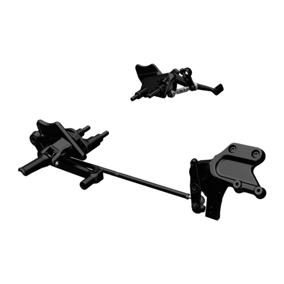
Kit pedane in posizione centrale
Footpeg kit in central position
Simbologia
Per una lettura rapida e razionale sono stati impiegati simboli che
evidenziano situazioni di massima attenzione, consigli pratici o
semplici informazioni.
Prestare molta attenzione al significato dei simboli, in quanto la
loro funzione è quella di non dovere ripetere concetti tecnici o
avvertenze di sicurezza. Sono da considerare, quindi, dei veri e
propri "promemoria" .
Consultare questa pagina ogni volta che sorgeranno dubbi sul loro
significato.
Attenzione
La non osservanza delle istruzioni riportate può creare una
situazione di pericolo e causare gravi lesioni personali e anche la
morte.
Importante
Indica la possibilità di arrecare danno al veicolo e/o ai suoi
componenti se le istruzioni riportate non vengono eseguite.
Note
Fornisce utili informazioni sull'operazione in corso.
Riferimenti
I particolari evidenziati in grigio e riferimento numerico (Es.
rappresentano l'accessorio da installare e gli eventuali componenti
di montaggio forniti a kit.
I particolari con riferimento alfabetico (Es.
componenti originali presenti sul motoveicolo.
Tutte le indicazioni destro o sinistro si riferiscono al senso di marcia
del motociclo.
Avvertenze generali
Attenzione
Le operazioni riportate nelle pagine seguenti devono essere
eseguite da un tecnico specializzato o da un'officina autorizzata
DUCATI.
Attenzione
Le operazioni riportate nelle pagine seguenti se non eseguite a
regola d'arte possono pregiudicare la sicurezza del pilota.
Note
Documentazione necessaria per eseguire il montaggio del Kit
è il MANUALE OFFICINA, relativo al modello di moto in vostro
possesso.
Note
Nel caso fosse necessaria la sostituzione di un componente del kit
consultare la tavola ricambi allegata.
1
)
A
) rappresentano i
Symbols
To allow quick and easy consultation, this manual uses graphic
symbols to highlight situations in which maximum care is required,
as well as practical advice or information.
Pay attention to the meaning of the symbols since they serve to
avoid repeating technical concepts or safety warnings throughout
the text. The symbols should therefore be seen as real reminders.
Please refer to this page whenever in doubt as to their meaning.
Warning
Failure to follow these instructions might give raise to a dangerous
situation and provoke severe personal injuries or even death.
Caution
Failure to follow these instructions might cause damages to the
vehicle and/or its components.
Notes
Useful information on the procedure being described.
References
Parts highlighted in grey and with a numeric reference
1
(Example
) are the accessory to be installed and any assembly
components supplied with the kit.
Parts with an alphabetic reference (Example
components fitted on the vehicle.
Any right- or left-hand indication refers to the vehicle direction of
travel.
General notes
Warning
Carefully perform the operations on the following pages since they
might negatively affect rider safety.
Warning
Carefully perform the operations on the following pages since they
might negatively affect rider safety.
Notes
The following documents are necessary for assembling the Kit:
WORKSHOP MANUAL of your bike model.
Notes
Should it be necessary to change any kit parts, please refer to the
attached spare part table.
96280411A
A
) are the original
1
Inhaltsverzeichnis

Verwandte Anleitungen für Ducati Performance ISTR-803/00


Inhaltszusammenfassung für Ducati Performance ISTR-803/00
- Seite 1 Le operazioni riportate nelle pagine seguenti devono essere Warning eseguite da un tecnico specializzato o da un’officina autorizzata Carefully perform the operations on the following pages since they DUCATI. might negatively affect rider safety. Attenzione Notes Le operazioni riportate nelle pagine seguenti se non eseguite a The following documents are necessary for assembling the Kit: regola d’arte possono pregiudicare la sicurezza del pilota.
- Seite 2 ISTR 803 / 00...
- Seite 3 Attenzione Warning Before using the motorcycle, check that the position of pedals Prima di utilizzare il motoveicolo, verificare che la posizione dei pedali e delle pedane permetta l'utilizzo corretto dei comandi in and footpegs allows control correct operation under all riding tutte le condizioni di guida.
- Seite 4 Smontaggio componenti originali Removing the original components Smontaggio cover puleggia Removing the pulley cover Operando sul lato sinistro del motoveicolo, svitare le n.2 viti (A1) Working on vehicle LH side, loosen no.2 screws (A1) and screw e la vite (A2) di fissaggio della cover puleggia (A) al coperchio (A2) fastening pulley cover (A) to generator cover (B).
- Seite 5 Smontaggio gruppo piastra portapedana sinistra LH footpeg holder plate unit removal Operando sul lato sinistro del motoveicolo, svitare la vite (D1) Working on vehicle LH side, loosen screw (D1) fastening LH di fissaggio del gruppo piastra portapedana sinistra (A) all'albero footpeg holder plate assembly (A) to splined shaft (I).
- Seite 6 Smontaggio gruppo piastra portapedana destra Removing RH footpeg holder plate unit Operando sul lato destro del motoveicolo, svitare le n.2 viti (G1) e By working on RH side of the motorcycle, loosen no.2 screws (G1) scostare la pompa freno posteriore (G) sfilando l’asta (G2). and move rear brake master cylinder (G) by sliding rod (G2) out.
- Seite 7 Notes Note To better understand how to disassemble the RH footpeg holder Per comprendere meglio lo smontaggio del gruppo piastra plate unit (L), the just-disassembled rear brake master cylinder unit portapedana destra (L) non viene rappresentato il gruppo pompa is not shown. freno posteriore appena smontato.
- Seite 8 RH footpeg holder plate unit disassembly Scomposizione gruppo piastra portapedana destra Loosen and remove pin (L3), no.2 O-rings (L2) and washer (L4). Svitare e rimuovere il perno (L3), i n.2 anelli OR (L2) e la rosetta (L4). Slide spring (S) out and remove rear brake lever (L1). Sfilare la molla (S) e rimuovere la leva freno posteriore (L1).
- Seite 9 5,5 Nm ± 10% 5 Nm ± 10% 72,3 mm 10 Nm ± 10% 10 Nm ± 10% Montaggio componenti kit Kit installation Caution Importante Verificare, prima del montaggio, che tutti i componenti risultino Check that all components are clean and in perfect condition before installation.
- Seite 10 18 Nm ± 10% 10 Nm ± 10% 42 Nm ± 10% 23 Nm ± 10% 42 Nm ± 10% 10 Nm ± 10% ISTR 803 / 00...
- Seite 11 Premontaggio gruppo piastra portapedana sinistra LH footpeg holder plate unit pre-assembly Inserire la molla (14), orientandola come mostrato in figura, Fit spring (14), positioning it as shown in the figure, inside footpeg all’interno della pedana (3). (3). Montare la pedana (3) sull’attacco pedana regolabile sinistro (2), Mount footpeg (3) on the LH adjustable footpeg mounting (2), avendo cura di introdurre l’estremità...
- Seite 12 6 Nm ± 10% 6 Nm ± 10% Rimontaggio cover puleggia Reassembling the pulley cover Applicare LOCTITE 243 sul filetto delle n.2 viti originali (A1) e della Apply LOCTITE 243 on the thread of no.2 original screws (A1) and viti originale (A2). original screw (A2).
- Seite 13 5 Nm ± 10% 7,5 Nm ± 10% 23 Nm ± 10% 47,5 mm Premontaggio gruppo supporto pompa freno posteriore Pre-assembling the rear brake master cylinder support assembly Montare la boccola (39) nel foro del rinvio (26), centrandola rispetto alla sede come mostrato nel riquadro. Fit bushing (39) in the hole of transmission (26), centring it with Applicare grasso bianco all'interno della boccola (39), sui n.2 OR respect to the seat as shown in the box.
- Seite 14 18 Nm ± 10% 2 Nm ± 10% 25 Nm ± 10% 10 Nm ± 10% ISTR 803 / 00...
- Seite 15 Montaggio gruppo supporto pompa freno posteriore Assembling the rear brake master cylinder support assembly Applicare Loctite 243 sul filetto delle n.2 viti originali (C). Posizionare il piastrino coprifori destro (5) sul supporto radiatori (F) Apply Loctite 243 on the thread of no.2 original screws (C). e impuntare le n.2 viti (C).
- Seite 16 10 Nm ± 10% 5 Nm ± 10% 23 Nm ± 10% 5 Nm ± 10% 373 mm ISTR 803 / 00...
- Seite 17 Premontaggio gruppo leva freno posteriore Pre-assembling the rear brake lever assembly Applicare grasso bianco all'interno del foro della leva freno Apply white grease inside rear brake lever hole (25), on no.2 posteriore (25), sui n.2 OR (12) e sul perno (15) escludendo la parte O-rings (12) and on pin (15), except on the threaded part.
- Seite 18 10 Nm ± 10% 42 Nm ± 10% 10 Nm ± 10% 4,5 mm 5 Nm ± 10% ISTR 803 / 00...
- Seite 19 Montaggio gruppo pedana destra Assembling RH footpeg assembly Applicare Loctite 601 sul filetto delle n.2 viti (37). Apply Loctite 601 on the thread of no.2 screws (37). Posizionare il gruppo piastra portapedana destra (23) sulla piastra Position RH footpeg holder plate assembly (23) on RH plate (R) destra (R) interponendo i n.2 distanziali (28) e impuntare le n.2 viti placing no.2 spacers (28) in-between, and start no.2 screws (37) in (37).
- Seite 20 NOTE / NOTES ISTR 803 / 00...
- Seite 21 ISTR - 803 / 00 96280411A Kit repose-pieds en position centrale Kit Fußrasten in mittlerer Position Symboles Symbole Pour faciliter la consultation de ce manuel, des symboles signalent Zum schnellen und übersichtlichen Lesen werden Symbole des situations exigeant le maximum d'attention, des conseils verwendet, die außerordentlich wichtige Situationen, praktische pratiques ou de simples informations.
- Seite 22 ISTR 803 / 00...
- Seite 23 Attention Achtung Avant de se mettre en route, vérifier que la position des pédales Vor dem Einsatz des Motorrads überprüfen, dass die Position der et des repose-pieds permet l'utilisation correcte des commandes Pedalen und der Fußrasten ihr korrektes Betätigen unter allen dans toutes les conditions de conduite.
-
Seite 24: Ausbau Der Original-Bestandteile
Dépose composants d'origine Ausbau der Original-Bestandteile Dépose du cache poulie Abnahme der Riemenscheibenabdeckung En agissant du côté gauche du motocycle, desserrer les 2 vis An der linken Seite des Motorrads die 2 Schrauben (A1) und die (A1) et la vis (A2) de fixation du cache poulie (A) au couvercle Schraube (A2) der Befestigung der Riemenscheibenabdeckung (A) d'alternateur (B). - Seite 25 Dépose ensemble platine de support repose-pied gauche Abnahme der Einheit der linken Fußrastenhalterplatte En intervenant du côté gauche du motocycle, desserrer la vis (D1) An der linken Motorradseite die Schraube (D1) der Befestigung der fixant l’ensemble platine de support repose-pied gauche (A) à Einheit der linken Fußrastenhalterplatte (A) an der verzahnten Welle l’arbre à...
- Seite 26 Dépose ensemble platine de support repose-pied droite Abnahme der Einheit der rechten Fußrastenhalterplatte En agissant du côté droit du motocycle, desserrer les 2 vis (G1) An der rechten Seite des Motorrads die 2 Schrauben (G1) lösen, et dégager le maître-cylindre de frein arrière (G) en sortant la tige dann den hinteren Bremszylinder (G) nach dem Herausziehen des (G2).
- Seite 27 Remarques Hinweis Pour mieux comprendre la dépose de l’ensemble platine de Zum besseren Verständnis des Ausbaus der Einheit der rechten support repose-pied droite (L), l’ensemble maître-cylindre de frein Fußrastenhalterplatte (L) wird hier die Einheit der soeben arrière que l’on vient de déposer n’est pas représenté. ausgebauten hinteren Bremspumpe nicht dargestellt.
- Seite 28 Désassemblage ensemble platine de support repose-pied Zerlegen der Einheit der rechten Fußrastenhalterplatte droite Den Bolzen (L3) lösen, dann gemeinsam mit den 2 O-Ringen (L2) Dévisser et déposer l'axe (L3), les 2 joints toriques (L2) et la und der Unterlegscheibe (L4) entfernen. rondelle (L4).
-
Seite 29: Montage Der Komponenten Des Kits
5,5 Nm ± 10% 5 Nm ± 10% 72,3 mm 10 Nm ± 10% 10 Nm ± 10% Pose composants kit Montage der Komponenten des Kits Important Wichtig Vérifier, avant la pose, que tous les composants sont propres et en Vor der Montage überprüfen, dass sich alle Komponenten im parfait état. - Seite 30 18 Nm ± 10% 10 Nm ± 10% 42 Nm ± 10% 23 Nm ± 10% 42 Nm ± 10% 10 Nm ± 10% ISTR 803 / 00...
- Seite 31 Pré-montage ensemble platine de support repose-pied Vormontage der Einheit der linken Fußrastenhalterplatte gauche Die Feder (14) einfügen und sie dabei wie abgebildet in der Insérer le ressort (14) à l’intérieur du repose-pieds (3), en Fußraste (3) ausrichten. l'orientant comme la figure le montre. Die Fußraste (3) am Anschluss der einstellbaren linken Fußraste (2) Poser le repose-pieds (3) sur la fixation repose-pied réglable montieren und dabei das Ende (14A) der Feder in die Bohrung (2A)
- Seite 32 6 Nm ± 10% 6 Nm ± 10% Repose du cache poulie Montage der Riemenscheibenabdeckung Enduire le filet des 2 vis d’origine (A1) et de la vis d’origine (A2) de LOCTITE 243 auf das Gewinde der 2 Original-Schrauben (A1) und LOCTITE 243.
- Seite 33 5 Nm ± 10% 7,5 Nm ± 10% 23 Nm ± 10% 47,5 mm Pré-montage ensemble support maître-cylindre de frein Vormontage des Halters des hinteren Bremszylinders arrière Die Buchse (39) in der Bohrung des Vorgeleges (26) montieren und Poser la bague (39) dans le trou du renvoi (26), en la centrant par dabei wie in der Detaildarstellung zum Sitz zentrieren.
- Seite 34 18 Nm ± 10% 2 Nm ± 10% 25 Nm ± 10% 10 Nm ± 10% ISTR 803 / 00...
- Seite 35 Montage ensemble support maître-cylindre de frein arrière Montage des Halters des hinteren Bremszylinders Enduire le filet des 2 vis d’origine (C) de Loctite 243. Loctite 243 auf das Gewinde der 2 Original-Schrauben (C) Positionner la plaquette couvre-trous droit (5) sur le support auftragen.
- Seite 36 10 Nm ± 10% 5 Nm ± 10% 23 Nm ± 10% 5 Nm ± 10% 373 mm ISTR 803 / 00...
- Seite 37 Pré-montage ensemble levier de frein arrière Vormontage der hinteren Bremshebeleinheit Appliquer de la graisse blanche dans le trou du levier de frein Weißes Fett in die Bohrung des Hinterradbremshebels (25), auf arrière (25), sur les 2 joints toriques (12) et sur l'axe (15) en die 2 O-Ringe (12) und auf den Bolzen (15), jedoch nicht auf den excluant la partie filetée.
- Seite 38 10 Nm ± 10% 42 Nm ± 10% 10 Nm ± 10% 4,5 mm 5 Nm ± 10% ISTR 803 / 00...
- Seite 39 Montage ensemble repose-pieds droit Montage der rechten Fußrasteneinheit Appliquer du Loctite 601 sur le filet des 2 vis (37). Loctite 601 auf das Gewinde der 2 Schrauben (37) auftragen. Positionner l’ensemble platine de support repose-pied droit (23) Die Einheit der rechten Fußrastenhalterplatte (23) an der rechten sur la plaque droite (R) en interposant les 2 entretoises (28) et Platte (R) anordnen und die 2 Distanzstücke (28) zwischensetzen und die 2 Schrauben (37) ansetzen.
- Seite 40 REMARQUES / HINWEIS ISTR 803 / 00...
-
Seite 41: Advertências Gerais
ISTR - 803 / 00 96280411A Conjunto de patins na posição central Footpeg kit in central position Símbolos Symbols Para uma leitura rápida e racional, foram utilizados símbolos que To allow quick and easy consultation, this manual uses graphic evidenciam situações de máxima atenção, conselhos práticos ou symbols to highlight situations in which maximum care is required, simples informações. - Seite 42 ISTR 803 / 00...
- Seite 43 Atenção Warning Antes de utilizar a moto, verifique se a posição dos pedais e dos Before using the motorcycle, check that the position of pedals patins permite utilizar corretamente os comandos em todas as and footpegs allows control correct operation under all riding condições de condução.
- Seite 44 Desmontagem dos componentes originais Removing the original components Desmontagem da cobertura da polia Removing the pulley cover Atuando no lado esquerdo da moto, desatarraxe os 2 parafusos Working on vehicle LH side, loosen no.2 screws (A1) and screw (A1) e o parafuso (A2) de fixação da tampa da polia (A) à tampa do (A2) fastening pulley cover (A) to generator cover (B).
- Seite 45 Desmontagem do grupo placa porta-patim esquerda LH footpeg holder plate unit removal Atuando no lado esquerdo da moto, desatarraxe o parafuso (D1) Working on vehicle LH side, loosen screw (D1) fastening LH de fixação do grupo placa porta-patim esquerda (A) ao veio do footpeg holder plate assembly (A) to splined shaft (I).
- Seite 46 Desmontagem do grupo placa porta-patim direita Removing RH footpeg holder plate unit Atuando pelo lado direito da moto, desatarraxe os 2 parafusos (G1) By working on RH side of the motorcycle, loosen no.2 screws (G1) e desvie a bomba do travão traseiro (G) retirando a haste (G2). and move rear brake master cylinder (G) by sliding rod (G2) out.
- Seite 47 Notas Notes Para compreender melhor a desmontagem do grupo placa To better understand how to disassemble the RH footpeg holder porta-patim direita (L), o grupo bomba do travão traseiro apenas plate unit (L), the just-disassembled rear brake master cylinder unit desmontado não é...
- Seite 48 Descomposição do grupo placa porta-patim direita RH footpeg holder plate unit disassembly Desatarraxe e remova o perno (L3), os 2 anéis OR (L2) e a anilha Loosen and remove pin (L3), no.2 O-rings (L2) and washer (L4). (L4). Slide spring (S) out and remove rear brake lever (L1). Retire a mola (S) e remova a alavanca do travão traseiro (L1).
-
Seite 49: Montagem Dos Componentes
5,5 Nm ± 10% 5 Nm ± 10% 72,3 mm 10 Nm ± 10% 10 Nm ± 10% Montagem dos componentes Kit installation Importante Caution Verifique, antes da montagem, se todos os componentes estão Check that all components are clean and in perfect condition limpos e em perfeito estado. - Seite 50 18 Nm ± 10% 10 Nm ± 10% 42 Nm ± 10% 23 Nm ± 10% 42 Nm ± 10% 10 Nm ± 10% ISTR 803 / 00...
- Seite 51 Pré-montagem do grupo placa porta-patim esquerda LH footpeg holder plate unit pre-assembly Insira a mola (14), direcionando-a como mostrado na figura, no Fit spring (14), positioning it as shown in the figure, inside footpeg interior do patim (3). (3). Monte o patim (3) no engate do patim regulável esquerdo (2), Mount footpeg (3) on the LH adjustable footpeg mounting (2), tendo o cuidado de introduzir a extremidade (14A) da mola no paying attention to insert end (14A) of the spring inside hole (2A).
- Seite 52 6 Nm ± 10% 6 Nm ± 10% Remontagem da cobertura da polia Reassembling the pulley cover Aplique LOCTITE 243 na rosca dos 2 parafusos originais (A1) e dos Apply LOCTITE 243 on the thread of no.2 original screws (A1) and parafusos originais (A2).
- Seite 53 5 Nm ± 10% 7,5 Nm ± 10% 23 Nm ± 10% 47,5 mm Pré-montagem do grupo de suporte da bomba do travão Pre-assembling the rear brake master cylinder support esquerdo assembly Monte o casquilho (39) no furo do reenvio (26), centrando-o em Fit bushing (39) in the hole of transmission (26), centring it with relação à...
- Seite 54 18 Nm ± 10% 2 Nm ± 10% 25 Nm ± 10% 10 Nm ± 10% ISTR 803 / 00...
- Seite 55 Montagem do grupo de suporte da bomba do travão traseiro Assembling the rear brake master cylinder support assembly Aplique Loctite 243 na rosca dos 2 parafusos originais (C). Posicione a placa de cobertura dos furos direita (5) no suporte dos Apply Loctite 243 on the thread of no.2 original screws (C).
- Seite 56 10 Nm ± 10% 5 Nm ± 10% 23 Nm ± 10% 5 Nm ± 10% 373 mm ISTR 803 / 00...
- Seite 57 Pré-montagem do grupo alavanca do travão traseiro Pre-assembling the rear brake lever assembly Aplique massa lubrificante branca no interior do furo da alavanca Apply white grease inside rear brake lever hole (25), on no.2 de travão traseira (25), nos 2 OR (12) e no perno (15) excluindo a O-rings (12) and on pin (15), except on the threaded part.
- Seite 58 10 Nm ± 10% 42 Nm ± 10% 10 Nm ± 10% 4,5 mm 5 Nm ± 10% ISTR 803 / 00...
- Seite 59 Montagem do grupo patim direito Assembling RH footpeg assembly Aplique Loctite 601 na rosca dos 2 parafusos (37). Apply Loctite 601 on the thread of no.2 screws (37). Posicione o grupo placa porta-patim direita (23) na placa direita (R) Position RH footpeg holder plate assembly (23) on RH plate (R) entrepondo os 2 espaçadores (28) e encoste os 2 parafusos (37).
- Seite 60 NOTAS / NOTES ISTR 803 / 00...
-
Seite 61: Advertencias Generales
ISTR - 803 / 00 96280411A Kit estribos en posición central センターポジションフットペグキット Símbolos シンボル Para una lectura rápida y racional se han empleado símbolos que 素早くかつ合理的に読み進めることができるように、本マニュア evidencian situaciones de máxima atención, consejos prácticos o ルではいくつかのシンボルを導入し、最大限の注意を払う必要が simples informaciones. Prestar mucha atención al significado de ある状況や、推奨事項、または一般情報を明確にしてあります。... - Seite 62 ISTR 803 / 00...
- Seite 63 Atención 注記 Antes de utilizar la motocicleta, controlar que la posición de los 車両をご使用になる前に、ペダルとフットペグがあらゆる運転状 pedales y de los estribos permita el uso correcto de los mandos en 況において運転操作の可能な位置にあることを確認してくださ todas las condiciones de conducción. い。 Pos. Denominacion 説明 Anillo de seguridad 安全リング...
- Seite 64 Desmontaje componentes originales オリジナル部品の取り外し Desmontaje cover polea プーリーカバーの取り外し Operando en el lado izquierdo de la motocicleta, desatornillar los 2 車両の左側で作業します。ジェネレーターカバー (B) にプーリー tornillos (A1) y el tornillo (A2) que fijan el cover polea (A) a la tapa カバー (A) を固定している 2 本のスクリュー (A1) およびスク alternador (B).
- Seite 65 Desmontaje grupo placa porta estribo izquierda 左フットペグホルダープレートユニットの取り外し Operando en el lado izquierdo de la motocicleta, desatornillar el 車両の左側で作業します。左フットペグホルダープレートユニッ tornillo (D1) que fija el grupo placa porta estribo izquierda (A) al eje ト (A) をスプラインシャフト (I) に固定しているスクリュー acanalado (I). (D1) を緩めて外します。 Desatornillar los 2 tornillos (D2) que fijan el grupo placa porta 左フットペグホルダープレートユニット...
- Seite 66 右フットペグホルダープレートユニットの取り外し Desmontaje grupo placa porta estribo derecha 車両の右側で作業します。2 本のスクリュー (G1) を緩めて外し Actuando del lado derecho de la motocicleta, desatornillar los 2 ます。ロッド (G2) を抜き取り、リアブレーキマスターシリンダ tornillos (G1) y desplazar la bomba freno trasero (G) extrayendo el vástago (G2). ー (G) を動かします。 重要...
- Seite 67 Notas 参考 Para comprender mejor el desmontaje del grupo placa porta 右フットペグホルダープレートユニット (L) の取り外し作業を分 estribo derecha (L), no se representa el grupo bomba freno trasero かりやすくするために、取り外したリアブレーキマスターシリン que se acaba de desmontar. ダーユニットは省略しています。 Operando en el lado derecho de la motocicleta, desatornillar los 車両の右側で作業します。右フットペグホルダープレートユニッ...
- Seite 68 Desmontaje grupo placa porta estribo derecha 右フットペグホルダープレートユニットの分解 Desatornillar y quitar el perno (L3), los 2 anillos tóricos (L2) y la ピン (L3)、2 個の Oリング (L2)、ワッシャー (L4) を緩めて取 arandela (L4). り外します。 Extraer el muelle (S) y quitar la leva freno trasero (L1). スプリング...
- Seite 69 5,5 Nm ± 10% 5 Nm ± 10% 72,3 mm 10 Nm ± 10% 10 Nm ± 10% Montaje componentes kit キット部品の取り付け Importante 重要 Controlar, antes del montaje, que todos los componentes se 取り付け前にすべての部品に汚れがなく、完璧な状態であること encuentren limpios y en perfecto estado. を確認します。作業する部品の外側表面を傷つけないために、必...
- Seite 70 18 Nm ± 10% 10 Nm ± 10% 42 Nm ± 10% 23 Nm ± 10% 42 Nm ± 10% 10 Nm ± 10% ISTR 803 / 00...
- Seite 71 Pre-montaje grupo placa porta estribo izquierda 左フットペグホルダープレートユニットの仮取り付け Introducir el muelle (14), orientándolo como ilustra la figura, en el スプリング (14) を図のように向け、フットペグ (3) の内側に挿 estribo (3). 入します。 Montar el estribo (3) en la conexión estribo regulable izquierda (2), フットペグ (3) を左アジャスタブルフットペグコネクター (2) prestando atención a introducir el extremo (14A) del muelle dentro に取り付けます。この時、スプリングの先端...
- Seite 72 6 Nm ± 10% 6 Nm ± 10% Montaje cover polea プーリーカバーの取り付け Aplicar LOCTITE 243 en la rosca de los 2 tornillos originales (A1) y 2 本のオリジナルスクリュー (A1) およびオリジナルスクリュー del tornillo original (A2). (A2) のネジ山に LOCTITE 243 を塗布します。 Colocar el cover polea original (A) en la tapa alternador (B) e 図のように、オリジナルプーリーカバー...
- Seite 73 5 Nm ± 10% 7,5 Nm ± 10% 23 Nm ± 10% 47,5 mm Pre-montaje grupo soporte bomba freno trasero リアブレーキシリンダーマウントユニットの仮取り付け Montar el casquillo (39) en el orificio del reenvío (26), centrándolo ブッシュ (39) をトランスミッション (26) の穴に取り付け、枠 en su alojamiento, como se muestra en el recuadro. 内に示す通り、取り付け位置に対して中心にくるようにします。...
- Seite 74 18 Nm ± 10% 2 Nm ± 10% 25 Nm ± 10% 10 Nm ± 10% ISTR 803 / 00...
- Seite 75 Montaje grupo soporte bomba freno trasero リアブレーキシリンダーマウントユニットの取り付け Aplicar Loctite 243 en la rosca de los 2 tornillos originales (C). 2 本のオリジナルスクリュー (C) のネジ山に LOCTITE 243 を塗 Posicionar la plaqueta cubre orificios derecha (5) en el soporte 布します。 radiadores (F) e introducir los 2 tornillos (C). 右ホールカバープレート...
- Seite 76 10 Nm ± 10% 5 Nm ± 10% 23 Nm ± 10% 5 Nm ± 10% 373 mm ISTR 803 / 00...
- Seite 77 Pre-montaje grupo leva freno trasero リアブレーキペダルユニットの仮取り付け Aplicar grasa blanca dentro del orificio de la leva freno trasero (25), リアブレーキペダル (25) の穴の内側、2 個の Oリング (12)、ピ en las 2 juntas tóricas (12) y en el perno (15), excluyendo la parte ン (15) のネジ山以外の部分にホワイトグリースを塗布します。 roscada.
- Seite 78 10 Nm ± 10% 42 Nm ± 10% 10 Nm ± 10% 4,5 mm 5 Nm ± 10% ISTR 803 / 00...
- Seite 79 Montaje grupo estribo derecho 右フットペグユニットの取り付け Aplicar Loctite 601 en la rosca de los 2 tornillos (37). 2 本のスクリュー (37) のネジ山に LOCTITE 601 を塗布します。 Posicionar el grupo placa porta estribo derecha (23) en la placa 2 個のスペーサー (28) を間にはさみ、右フットペグホルダープ derecha (R), interponiendo los 2 separadores (28) e introducir los 2 レートユニット...
- Seite 80 NOTAS / 参考 ISTR 803 / 00...
- Seite 81 DUCATI PERFORMANCE レース専用部品 ご注文書 ご注文商品 商品名 P/N P/N 商品名 商品名 P/N P/N 商品名 P/N 商品名 お客様ご記入欄 私は上記レース専用部品を下記車両に装着し、サーキット走行のみに 利用し、一般公道には利用しません。 車台番号 ZDM モデル名 お客様署名 ご注文日 ドゥカティ正規ネットワーク店記入欄 お客様に上記レース専用部品を販売し、レース専用部品のご利用方法を 説明いたしました。 販売店署名 販売日 年 月 日 販売店様へお願い 1. 上記ご記入の上、弊社アフターセールス部までFAXしてください。FAX:03-6692-1317 1. 上記ご記入の上、弊社アフターセールス部までFAXしてください。FAX:03-6692-1317 2. 取り付け車両1台に1枚でご使用ください。...