Ducati Performance ISTR-913/01 Montageanleitung
ISTR - 913 / 01
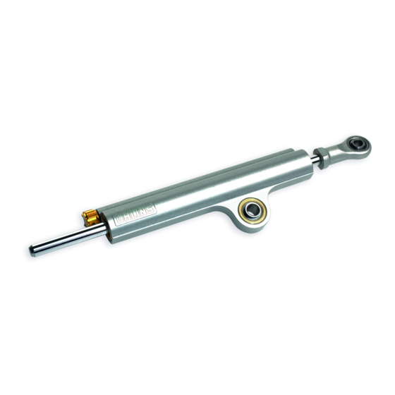
Kit ammortizzatore di sterzo
Steering damper kit
Simbologia
Per una lettura rapida e razionale sono stati impiegati simboli che
evidenziano situazioni di massima attenzione, consigli pratici o
semplici informazioni. Prestare molta attenzione al significato dei
simboli, in quanto la loro funzione è quella di non dovere ripete-
re concetti tecnici o avvertenze di sicurezza. Sono da considerare,
quindi, dei veri e propri "promemoria". Consultare questa pagina
ogni volta che sorgeranno dubbi sul loro significato.
Attenzione
La non osservanza delle istruzioni riportate può creare una situa-
zione di pericolo e causare gravi lesioni personali e anche la morte.
Importante
Indica la possibilità di arrecare danno al veicolo e/o ai suoi compo-
nenti se le istruzioni riportate non vengono eseguite.
Note
Fornisce utili informazioni sull'operazione in corso.
Riferimenti
I particolari evidenziati in grigio e riferimento numerico (Es.
rappresentano l'accessorio da installare e gli eventuali componenti
di montaggio forniti a kit.
I particolari con riferimento alfabetico (Es.
componenti originali presenti sul motoveicolo.
Tutte le indicazioni destro o sinistro si riferiscono al senso di marcia
del motociclo.
Avvertenze generali
Attenzione
Le operazioni riportate nelle pagine seguenti devono essere ese-
guite da un tecnico specializzato o da un'officina autorizzata Du-
cati.
Attenzione
Le operazioni riportate nelle pagine seguenti se non eseguite a re-
gola d'arte possono pregiudicare la sicurezza del pilota.
Note
Documentazione necessaria per eseguire il montaggio del Kit è il
Manuale Officina, relativo al modello di moto in vostro possesso.
Note
Nel caso fosse necessaria la sostituzione di un componente del kit
consultare la tavola ricambi allegata.
1
- 96280541A
- 96280541A
A
) rappresentano i
Symbols
The symbols used in this manual are aimed at making reading di-
rect and easy. The symbols are used either to draw the reader's
attention on potentially hazardous conditions, or to give practical
advice or to supply general information. Pay the utmost attention
to these symbols as they are used to remind of technical principles
or safety measures which will not be repeated extensively. They
must therefore be considered as "reminders". Check with this page
in case of doubt about their meaning.
Warning
Failure to comply with these instructions may put you at risk and
lead to severe injury or death.
Important
It indicates the possibility of damaging the motorcycle and/or its
components if the instructions are not followed.
Notes
It supplies useful information about the operation in progress.
References
1
)
The parts highlighted in grey and with a reference number (e.g.
) represent the accessory to be installed and any assembly compo-
nents supplied with the kit.
The parts with alphabetic reference (e.g.
components present on the motorcycle.
All left and right indications are referred to the motorcycle direc-
tion of travel (forward riding position).
General notes
Warning
The operations listed in the following pages must be carried out by
a specialised technician or by a Ducati authorised service centre.
Warning
Carefully perform the operations on the following pages since they
might negatively affect rider safety.
Notes
The Workshop Manual of your motorcycle model is the documen-
tation required to assemble the Kit.
Notes
Should it be necessary to change any kit parts, please refer to the
attached spare part table.
Warning
Operating, servicing and maintaining a passenger vehicle or off-
highway motor vehicle can expose you to chemicals including en-
gine exhaust, carbon monoxide, phthalates, and lead, which are
known to the State of California to cause cancer and birth defects
or other reproductive harm. To minimize exposure, avoid breath-
ing exhaust, do not idle the engine except as necessary, service
your vehicle in a well-ventilated area and wear gloves or wash your
hands frequently when servicing your vehicle. For more informa-
tion go to www.P65Warnings.ca.gov/passenger-vehicle.
1
A
) represent the original
Inhaltsverzeichnis

Verwandte Anleitungen für Ducati Performance ISTR-913/01


Inhaltszusammenfassung für Ducati Performance ISTR-913/01
- Seite 1 Du- The operations listed in the following pages must be carried out by cati. a specialised technician or by a Ducati authorised service centre. Attenzione Warning Le operazioni riportate nelle pagine seguenti se non eseguite a re- Carefully perform the operations on the following pages since they gola d’arte possono pregiudicare la sicurezza del pilota.
- Seite 2 ISTR 913 / 01 Importante Important I componenti del kit possono essere soggetti ad aggiornamenti; The parts of the kit can be updated; for information always up to consultare il DCS (Dealer Communication System) per avere infor- date, please refer to DCS (Dealer Communication System). mazioni sempre aggiornate.
- Seite 3 ISTR 913 / 01 Smontaggio componenti originali Original components disassembly Svitare i n.2 dadi speciali (B) dalla cover commutatore (A). Loosen no.2 special nuts (B) from switch cover (A).
- Seite 4 ISTR 913 / 01 Note Notes Per comprendere meglio lo smontaggio del semi manubrio destro, To better understand how to remove RH handlebar, the headlight non vengono rappresentati il cupolino e lo specchietto destro. fairing and the RH rear-view mirror are not shown. Svitare le n.2 viti (C).
- Seite 5 ISTR 913 / 01 Svitare le n.2 viti (E). Rimuovere e conservare le n.2 viti originali Undo the no.2 screws (E). Remove and keep the no.2 original (E). Rimuovere il supporto semi manubrio (F), sfilandolo dal fodero screws (E). Remove handlebar support (F), sliding it out of RH front forcella anteriore destro (G).
- Seite 6 ISTR 913 / 01 8Nm ± 10% 8 Nm ± 10% 10 Nm ± 10% 10 Nm ± 10% Montaggio componenti kit Kit part assembly Importante Important Verificare, prima del montaggio, che tutti i componenti risultino Before assembling, check that all parts are clean and in good con- puliti e in perfetto stato.
- Seite 7 ISTR 913 / 01 35Nm ± 5% 35 Nm ± 5% Montaggio supporto semi manubrio destro (solo Fitting the RH handlebar support per Supersport versione S) (Supersport, S version only) Posizionare il supporto semi manubrio destro (3) sul fodero for- Position RH handlebar support (3) on RH front fork sleeve (G), cella anteriore destro (G), appoggiandolo sulla testa di sterzo (H).
- Seite 8 ISTR 913 / 01 35Nm ± 5% 35 Nm ± 5% Montaggio supporto semi manubrio destro (solo Fitting the RH handlebar support (Supersport only) per Supersport) Warning Attenzione For Supersport models, it is necessary to use reducing bushing (4) Per i modelli Supersport, è necessario l'utilizzo della boccola di ri- because of the smaller diameter of front fork sleeve (G).
- Seite 9 ISTR 913 / 01 10Nm ± 5% Rimontaggio semi manubrio Refitting the handlebar Montare il semi manubrio destro (D) nella relativa sede sul suppor- Fit the RH handlebar (D) in its seat in the RH handlebar support to semi manubrio destro (3), posizionando il semi manubrio con lo (3), aiming the handlebar with recess (D1) facing ahead and the scasso (D1) rivolto in avanti e la bulinatura (D2) rivolta verso l'alto, engraving (D2) facing upward, matching the recess (D1) with the...
- Seite 10 ISTR 913 / 01 10Nm ± 10% 10Nm ± 10% Montaggio ammortizzatore di sterzo Steering damper assembly Premontare le n.2 guarnizioni OR (6), il distanziale (12) e il distan- Pre-assemble no.2 O-rings (6), spacer (12) and spacer (11) on damp- ziale (11) sull'ammortizzatore (1).
-
Seite 11: Avertissements Généraux
Ducati. Die auf den folgenden Seiten beschriebenen Arbeitsmaßnahmen müssen von einem Fachtechniker oder einer autorisierten Ducati- Attention Werkstatt ausgeführt werden. Les opérations indiquées dans les pages suivantes, au cas où elles Achtung ne seraient pas effectuées selon les règles de l'art pourraient com-... - Seite 12 ISTR 913 / 01 Important Wichtig Les composants du kit peuvent être soumis à des mises à jour ; Die Bestandteile des Kits können Aktualisierungen unterliegen. veuillez consulter le DCS (Dealer Communication System) pour des Lesen Sie stets die Angaben im DCS (Dealer Communication Sys- informations toujours actualisées.
-
Seite 13: Ausbau Der Original-Bestandteile
ISTR 913 / 01 Dépose des composants d'origine Ausbau der Original-Bestandteile Desserrer les 2 écrous spéciaux (B) du cache commutateur (A). Die 2 Spezialmuttern (B) von der Abdeckung der Umschalterein- heit (A) lösen. - Seite 14 ISTR 913 / 01 Remarques Hinweis Pour mieux comprendre la dépose du demi-guidon droit, la bulle et Zum besseren Verständnis der Abnahme des rechten Lenkerstum- le rétroviseur droit ne sont pas représentés. mels werden die Cockpitverkleidung und der rechte Spiegel nicht dargestellt.
- Seite 15 ISTR 913 / 01 Desserrer les 2 vis (E). Retirer et mettre de côté les 2 vis d’origine Die 2 Schrauben (E) lösen. Die 2 Original-Schrauben (E) entfernen (E). Déposer le support demi-guidon (F), en le sortant du fourreau und aufbewahren. Den Halter des Lenkerstummels (F) entfernen, fourche avant droit (G).
-
Seite 16: Montage Der Bestandteile Des Kits
ISTR 913 / 01 8Nm ± 10% 8 Nm ± 10% 10 Nm ± 10% 10 Nm ± 10% Pose des composants kit Montage der Bestandteile des Kits Important Wichtig Avant la pose, vérifier que tous les composants sont propres et en Vor der Montage überprüfen, dass alle Bestandteile sauber sind bon état. - Seite 17 ISTR 913 / 01 35Nm ± 5% 35 Nm ± 5% Pose du support demi-guidon droit (seulement pour Montage des Halters des rechten Lenkerstummels Supersport version S) (nur bei Supersport Version S) Positionner le support demi-guidon droit (3) sur le fourreau fourche Den Halter des rechten Lenkerstummels (3) am rechten Stan- avant droit (G), en l’appuyant sur le té...
- Seite 18 ISTR 913 / 01 35Nm ± 5% 35 Nm ± 5% Pose du support demi-guidon droit (seulement pour Montage des Halters des rechten Lenkerstummels Supersport) (nur bei Supersport) Attention Achtung Pour les modèles Supersport, il est nécessaire d'utiliser la bague Bei den Modellen Supersport ist es aufgrund des kleineren Durch- de réduction (4) à...
- Seite 19 ISTR 913 / 01 10Nm ± 5% Repose du demi-guidon Montage des Lenkerstummels Poser le demi-guidon droit (D) dans son logement sur le support Den rechten Lenkerstummel (D) wie abgebildet in seinem Sitz demi-guidon droit (3), en positionnant le demi-guidon avec le cran am Halter des rechten Lenkerstummels (3) montieren, dabei den (D1) tourné...
- Seite 20 ISTR 913 / 01 10Nm ± 10% 10Nm ± 10% Pose amortisseur de direction Montage des Lenkungsdämpfers Pré-monter les 2 joints toriques (6), l’entretoise (12) et l’entretoise Die 2 O-Ringe (6), das Distanzstück (12) und das Distanzstück (11) (11) sur l’amortisseur (1). Positionner l'ensemble amortisseur (1) am Schwingungsdämpfer (1) vormontieren.
-
Seite 21: Advertências Gerais
As operações mostradas nas páginas a seguir devem ser execu- The operations listed in the following pages must be carried out by tadas por um técnico especializado ou por uma oficina autorizada a specialised technician or by a Ducati authorised service centre. Ducati. Warning Atenção... - Seite 22 ISTR 913 / 01 Importante Important Os componentes do conjunto podem sofrer atualizações; consulte The parts of the kit can be updated; for information always up to o DCS (Dealer Communication System) a fim de obter informações date, please refer to DCS (Dealer Communication System). sempre atualizadas.
- Seite 23 ISTR 913 / 01 Desmontagem dos componentes originais Original components disassembly Desatarraxe as 2 porcas especiais (B) da cobertura do comutador Loosen no.2 special nuts (B) from switch cover (A). (A).
- Seite 24 ISTR 913 / 01 Notas Notes Para compreender melhor a desmontagem do semi-guiador direi- To better understand how to remove RH handlebar, the headlight to, a cúpula e o espelho direito não estão representados. fairing and the RH rear-view mirror are not shown. Desatarraxe os 2 parafusos (C).
- Seite 25 ISTR 913 / 01 Desatarraxe os 2 parafusos (E). Remova e guarde os 2 parafusos Undo the no.2 screws (E). Remove and keep the no.2 original originais (E). Remova o suporte semi-guiador (F), removendo-o da screws (E). Remove handlebar support (F), sliding it out of RH front manga da forquilha dianteira direita (G).
- Seite 26 ISTR 913 / 01 8Nm ± 10% 8 Nm ± 10% 10 Nm ± 10% 10 Nm ± 10% Montagem dos componentes do conjunto Kit part assembly Importante Important Verifique, antes da montagem, se todos os componentes estão Before assembling, check that all parts are clean and in good con- limpos e em perfeito estado.
- Seite 27 ISTR 913 / 01 35Nm ± 5% 35 Nm ± 5% Montagem do suporte do semi-guiador direito Fitting the RH handlebar support (apenas para Supersport versão S) (Supersport, S version only) Posicione o suporte do semi-guiador direito (3) na manga da for- Position RH handlebar support (3) on RH front fork sleeve (G), quilha dianteira direita (G), apoiando na cabeça de direção (H).
- Seite 28 ISTR 913 / 01 35Nm ± 5% 35 Nm ± 5% Montagem do suporte do semi-guiador direito Fitting the RH handlebar support (Supersport only) (apenas para Supersport) Warning Atenção For Supersport models, it is necessary to use reducing bushing (4) Para os modelos Supersport, é...
- Seite 29 ISTR 913 / 01 10Nm ± 5% Remontagem do semi-guiador Refitting the handlebar Monte o semi-guiador direito (D) na sede correspondente no su- Fit the RH handlebar (D) in its seat in the RH handlebar support porte do semi-guiador direito (3), posicionando o semi-guiador (3), aiming the handlebar with recess (D1) facing ahead and the com a cavidade (D1) virada para a frente e o punção (D2) virado engraving (D2) facing upward, matching the recess (D1) with the...
- Seite 30 ISTR 913 / 01 10Nm ± 10% 10Nm ± 10% Montagem do amortecedor de direção Steering damper assembly Monte previamente os dois anéis OR (6) e os espaçadores (11 e Pre-assemble no.2 O-rings (6), spacer (12) and spacer (11) on damp- 12) no amortecedor (1).
-
Seite 31: Advertencias Generales
Advertencias generales 警告 Atención 以下のページに記載されている作業は、専門の技術者、またはド Las operaciones indicadas en las páginas siguientes debe realizar- ゥカティ正規サービスセンターが実施しなければなりません。 las un técnico especializado o un taller autorizado Ducati. 警告 Atención 以下のページに記載されている作業が規定通りに実施されない Las operaciones descritas en las siguientes páginas deben realizar- と、ライダーの安全性を脅かすおそれがあります。 se correctamente para no perjudicar la seguridad del piloto. - Seite 32 ISTR 913 / 01 Importante 重要 Es posible que los componentes del kit sean actualizados; consul- キットの構成部品は更新されることがあります。DCS (Dealer tar el DCS (Dealer Communication System) para tener información Communication System) から常に最新の情報をチェックするよ siempre al día. うにしてください。 Pos. Denominación 名称 Amortiguador de dirección ステアリングダンパー...
- Seite 33 ISTR 913 / 01 Desmontaje componentes originales オリジナル構成部品の取り外し Desatornillar las 2 tuercas especiales (B) del cover conmutador (C). イグニッションスイッチカバー (A) から 2 個の専用ナット (B) を緩めて外します。...
- Seite 34 ISTR 913 / 01 Notas 参考 Para comprender mejor el desmontaje del semimanillar derecho, 右ハンドルバーの取り外しを分かりやすくするために、図中では no se muestran la cúpula ni el espejo derecho. ヘッドライトフェアリングと右リアビューミラーは省略されてい ます。 Desatornillar los 2 tornillos (C). Quitar y conservar los 2 tornillos originales (C). Quitar el grupo semimanillar derecho (D), apoyán- 2 本のスクリュー...
- Seite 35 ISTR 913 / 01 Desatornillar los 2 tornillos (E). Quitar y conservar los 2 tornillos 2 本のスクリュー (E) を緩めて外します。2 本のオリジナルス originales (E). Quitar el soporte semimanillar (F), quitándolo del クリュー (E) を外し、保管しておきます。ハンドルバーマウント tubo externo horquilla delantera derecha (G). (F) を右フロントフォークのアウターチューブ (G) から抜いて取 り外します。...
- Seite 36 ISTR 913 / 01 8Nm ± 10% 8 Nm ± 10% 10 Nm ± 10% 10 Nm ± 10% Montaje componentes kit キット部品の取り付け Importante 重要 Antes del montaje, comprobar que todos los componentes se en- 取り付けの前に全ての部品に汚れがなく、完璧な状態であること cuentren limpios y en perfecto estado. Adoptar todas las precau- を確認してください。作業する部分が破損しないように、必要な...
- Seite 37 ISTR 913 / 01 35Nm ± 5% 35 Nm ± 5% Montaje soporte semimanillar derecho (solo para 右ハンドルバーの取り付け Supersport versión S) (Supersport バージョン S のみ) Colocar el soporte semimanillar derecho (3) en el tubo externo 右ハンドルバーマウント (3) を右フロントフォークのアウターチ horquilla delantera derecha (G), apoyándolo en la tija superior (H). ューブ...
- Seite 38 ISTR 913 / 01 35Nm ± 5% 35 Nm ± 5% Montaje soporte semimanillar derecho (solo para 右ハンドルバーの取り付け (Supersport のみ) Supersport) 警告 Atención Supersport モデルについては、フロントフォークのアウターチュ Para los modelos Supersport, es necesario el uso del casquillo de ーブ (G) の直径が小さいためリダクションブッシュ (4) を使用 reducción (4) debido al diámetro menor del tubo externo horquilla する必要があります。...
- Seite 39 ISTR 913 / 01 10Nm ± 5% Montaje semimanillar ハンドルバーの取り付け Montar el semimanillar derecho (D) en el alojamiento relativo en el 右ハンドルバー (D) を右ハンドルバーマウント (3) の所定の位 soporte semimanillar derecho (3), colocando el semimanillar con la 置に取り付けます。このとき、枠図内に示すようにハンドルバー muesca (D1) dirigida hacia adelante y la parte burilada (D2) dirigida の溝...
- Seite 40 ISTR 913 / 01 10Nm ± 10% 10Nm ± 10% Montaje amortiguador de dirección ステアリングダンパーの取り付け Premontar las 2 juntas tóricas (6), el separador (12) y el separador 2 個の Oリング (6)、スペーサー (12)、スペーサー (11) をダ (11) en el amortiguador (1). Colocar el grupo amortiguador (1) en el ンパー...
- Seite 41 レース専用部品 ご注文書 ご注文商品 商品名 P/N 商品名 P/N 商品名 P/N 商品名 P/N 商品名 P/N お客様ご記入欄 私は上記レース専用部品を下記車両に装着し、サーキット走行のみに 利用し、一般公道には利用しません。 車台番号 ZDM モデル名 お客様署名 ご注文日 ドゥカティ正規ネットワーク店記入欄 お客様に上記レース専用部品を販売し、レース専用部品のご利用方法を 説明いたしました。 販売店署名 販売日 年 月 日 販売店様へお願い 1. 上記ご記入の上、弊社アフターセールス 部までFAX してください 。FAX : 03 - 6692 - 1317 1. 上記ご記入の上、弊社アフターセールス 部までFAX してください 。FAX : 03 - 6692 - 1317 2.