Inhaltsverzeichnis
-
-
-
-
Description of the Appliance
10
-
Eligible Patient Group
10
-
Patient Selection Criteria
10
-
-
-
-
-
-
-
-
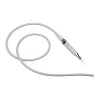
Scaler Handpiece Identification Data
15
-
Inserts Identification Data
15
-
-
-
-
Safety Requirements During Installation
20
-
Mechanical Installation
21
-
Electrical Connections
21
-
Alternate 24V Power Supply
23
-
Direct 32V Power Supply
23
-
-
Power Regulation with 2.2 Kohm Potentiometer
23
-
Power Regulation with 10 Kohm Potentiometer
24
-
Power Regulation with 4.7 Kohm Potentiometer
24
-
-
-
Solenoid Valve Control
25
-
-
Enabling of Pedal with Negative Signal
25
-
Enabling of Pedal with Positive Signal
26
-
-
Connecting the Cord of the Scaler Handpiece
27
-
-
-
-
-
-
-
-
-
-
-
Methods and Precautions for Disposal
33
-
-
Guide and Manufacturer's Declaration - Electromagnetic Emissions
35
-
Accessible Parts of the Casing
36
-
Guide and the Manufacturer's Declaration - Electromagnetic Immunity
37
-
Power Connection BC Input
37
-
Points of Contact with the Patient
39
-
Parts Accessible to the Input / Output Signals
40
-
Specifications of the Tests for the Immunity of the Accessible Parts of the Casing to the Wireless RF Communications Device
41
-
-
-
Shipping to an Authorised Mectron Service Centre
45
-
-
-
-
Descrizione Dell'apparecchio
56
-
Gruppo DI Pazienti Previsto
56
-
Criteri DI Selezione Dei Pazienti
56
-
-
-
Declinazione DI Responsabilità
57
-
Prescrizioni DI Sicurezza
58
-
-
Dati DI Identificazione
60
-
Targa DI Identificazione Apparecchio
60
-
Dati DI Identificazione del Manipolo Ablatore
61
-
Dati DI Identificazione Inserti
61
-
-
-
-
Prescrizioni DI Sicurezza Durante L'installazione
66
-
Installazione Meccanica
67
-
Collegamenti Elettrici
67
-
Alimentazione 24V Alternata
69
-
Alimentazione 32V Continua
69
-
Regolazione Della Potenza 0-5 V
69
-
Regolazione Della Potenza con Potenziometro da 2,2 Kohm
69
-
Regolazione Della Potenza con Potenziometro da 10 Kohm
69
-
Regolazione Della Potenza 0-10 V
71
-
Controllo Elettrovalvola
71
-
-
Abilitazione del Pedale con Segnale Negativo
71
-
Abilitazione del Pedale con Segnale Positivo
72
-
-
Collegamento del Cordone del Manipolo Ablatore
73
-
-
-
-
-
-
-
-
-
-
Collegamento Idraulico
78
-
Modalità E Precauzioni Per lo Smaltimento
79
-
-
Guida E Dichiarazione Elettromagnetiche
81
-
Parti Accessibili Dell'involucro
82
-
Connessione Potenza A.C. D'ingresso
83
-
Punti DI Contatto con Il Paziente
85
-
Parti Accessibili Ai Segnali DI Ingresso / Uscita
86
-
Specifiche Dei Test Per L'immunità Delle Parti Accessibili Dell'involucro All'apparecchiatura DI Comunicazioni RF Wireless
87
-
Risoluzione Dei Problemi
88
-
-
Risoluzione Rapida Dei Problemi
89
-
Invio a un Centro Assistenza Autorizzato Mectron
91
-
-
-
-
-
-
-
-
-
-
-
-
-
-
-
-
-
-
-
-
-
-
-
-
-
-
-
-
-
-
-
-
-
-
-
-
-
-
-
-
-
-
-
-
-
-
-
-
-
-
-
-
-
-
-
-
-
-
-
-
Description de L'appareil
148
-
Groupe de Patients Prévu
148
-
Critères de Sélection des Patients
148
-
Indications pour L'utilisation
148
-
-
Avis de Non-Responsabilité
149
-
Consignes de Sécurité
149
-
-
Données D'identification
152
-
Plaque D'identification de L'appareil
152
-
Données D'identification de la Pièce à Main Détartreur
153
-
Données D'identification des Inserts
153
-
-
La Liste des Composants
154
-
-
Consignes de Sécurité Durant L'installation
158
-
Installation Mécanique
159
-
Branchements Électriques
159
-
Alimentation 24V Alternative
161
-
Alimentation 32V Continue
161
-
Réglage de la Puissance
161
-
Réglage de la Puissance Avec Potentiomètre de 2,2 Kohm
161
-
Réglage de la Puissance Avec Potentiomètre de 10 Kohm
162
-
Réglage de la Puissance Avec Potentiomètre de 4,7 Kohm
162
-
Contrôle de L'électrovanne
163
-
-
Activation de la Pédale Avec Signal Positif
164
-
-
Branchement du Cordon de la Pièce à Main Détartreur
164
-
-
-
-
-
-
-
-
-
-
Connexion Hydraulique
170
-
Méthodes et Précautions pour L'élimination
171
-
-
Guide et Déclaration du Constructeur - Émissions Électromagnétiques
173
-
Parties de la Coque Accessibles
174
-
Guide et Déclaration du Constructeur - Immunité Électromagnétique
175
-
Raccordement Puissance C.A. D'entrée
175
-
Points de Contact Avec le Patient
177
-
Décharge Électrostatique
177
-
Pièces Accessibles aux Signaux D'entrée/Sortie
178
-
Spécifications de Test pour L'immunité des Parties de la Coque Qui Sont Accessibles aux Équipements de Communication Radioélectrique Sans Fil
179
-
Résolution des Problèmes
180
-
-
Résolution Rapide des Problèmes
181
-
Envoi Vers un Centre D'assistance Agréé Mectron
183
-
-
-
-
Descripción del Dispositivo
194
-
Grupo de Pacientes a Los que Se Destina
194
-
Criterios de Selección de Pacientes
194
-
-
-
Declinación de Responsabilidad
195
-
Prescripciones de Seguridad
196
-
-
Datos de Identificación
198
-
Placa de Identificación del Aparato
198
-
Datos de Identificación de la Pieza de Mano Escariador
199
-
Datos de Identificación de Los Insertos
199
-
-
Lista de Los Componentes
200
-
-
Precauciones de Seguridad Durante la Instalación
204
-
-
Conexiones Eléctricas
205
-
Alimentación 24V Alterna
207
-
Alimentación 32V Continua
207
-
Regulación de la Potencia
207
-
Regulación de la Potencia con Potenciómetro de 2,2 Kohm
207
-
Regulación de la Potencia con Potenciómetro de 10 Kohm
208
-
Regulación de la Potencia con Potenciómetro de 4,7 Kohm
208
-
Control Electroválvula
209
-
-
Habilitación del Pedal con Señal Positiva
210
-
-
Conexión del Cordón de la Pieza de Mano Escariador
211
-
-
-
-
-
-
-
-
-
-
-
Modalidad y Precauciones para la Eliminación
217
-
-
Guía y Declaración del Fabricante - Emisiones Electromagnéticas
219
-
Partes Accesibles de la Envoltura
220
-
Guía y Declaración del Fabricante - Inmunidad Electromagnética
221
-
Conexión Potencia A.C. de Entrada
221
-
Puntos de Contacto con el Paciente
223
-
Partes Accesibles a las Señales de Entrada / Salida
224
-
Especificaciones de las Pruebas para la Inmunidad de las Partes Accesibles de la Envoltura en Los Aparatos de Comunicaciones RF Wireless
225
-
Solución de Problemas
226
-
-
Solución Rápida de Los Problemas
227
-
Envío a un Centro de Asistencia Autorizado Mectron
229
-
-
-
-
Beskrivning Av Anordningen
240
-
Förutsedd Patientgrupp
240
-
Kriterier För Val Av Patienterna
240
-
Anvisningar För Användningen
240
-
-
-
Säkerhetsföreskrifter
242
-
-
Identifieringsuppgifter
244
-
Anordningens Identifikationsskylt
244
-
Identifieringsuppgifter För Scalerns Handstycke
245
-
-
Spetsarnas Identifikationsuppgifter
245
-
-
Lista Över Komponenter
246
-
-
Säkerhetsföreskrifter under Installationen
250
-
Mekanisk Installation
251
-
-
Matning 24V VäxelströM
253
-
-
Justering Av Effekten
253
-
Justering Av Effekt Med Potentiometer På 2,2 Kohm
253
-
Justering Av Effekt Med Potentiometer På 10 Kohm
254
-
Justering Av Effekt Med Potentiometer På 4,7 Kohm
254
-
Kontroll Av Magnetventil
255
-
-
Aktivering Av Pedalen Med Positiv Signal
256
-
-
Anslutning Av Scaler Handstyckets Sladd
257
-
-
-
-
-
-
-
-
-
-
-
Tillvägagångssätt För Bortskaffande
263
-
-
Riktlinjer Och Tillverkarens Förklaring Om Elektromagnetiska Störningar
265
-
Höljets Åtkomliga Delar
266
-
Riktlinjer Och Tillverkarens Förklaring Om Elektromagnetiska Störningar
267
-
Strömanslutning Ingång
267
-
Kontaktpunkter Med Patienten
269
-
Delar Som Är Tillgängliga För in / Utgångssignaler
270
-
Specifikationer För Immunitetstestet Av de Tillgängliga Delarna Av Kapslingen Till RF-Trådlös Kommunikationsutrustning
271
-
-
-
Snabbt Åtgärdande Av Fel
273
-
Försändelse Till en Kundtjänst Auktoriserad Av Mectron
275
-