Herunterladen Inhalt Inhalt Diese Seite drucken
Grundfos Control MPC-Serie Installationsanleitung
Vorschau ausblenden Andere Handbücher für Control MPC-Serie:
Inhaltsverzeichnis

Werbung

Verfügbare Sprachen
  • DE

Verfügbare Sprachen

  • DEUTSCH, seite 75
GRUNDFOS INSTRUCTIONS
Control MPC
Installation and operating instructions

Werbung

Inhaltsverzeichnis
loading

Inhaltszusammenfassung für Grundfos Control MPC-Serie

  • Seite 1 GRUNDFOS INSTRUCTIONS Control MPC Installation and operating instructions...
  • Seite 3 Control MPC English (GB) Installation and operating instructions ............4 Deutsch (DE) Montage- und Betriebsanleitung .
  • Seite 4 Buttons and indicator lights - Action to avoid the hazard. Functions 1.2 Notes Tree of functions The symbols and notes below may appear in Grundfos Overview installation and operating instructions, safety instructions and Description of functions service instructions. Status (1)
  • Seite 5: Electrical Installation

    8. The system is now ready for operation. Fig. 1 Correct lifting of control cabinet Grundfos can supply hydraulic data for CR, CRI, CRN, CRE, CRIE and CRNE pumps where GSC files Use suitable lifting equipment that is in good condition and can be downloaded to CU 352.
  • Seite 6: Product Introduction

    Control 5.1 Product description Description variant Grundfos Control MPC is mainly used for control and monitoring of booster and circulation systems. Two to six pumps with integrated frequency converter (0.37 - 22 kW). Control MPC consists of a control cabinet with a built-in controller, CU 352.
  • Seite 7 * Applies only to booster systems. Fig. 2 Nameplate ** Applies only to CR, CRI, CRN, CRE and CRIE pumps. Pos. Description A GSC (Grundfos Standard Configuration) file is a Product type configuration data file. Code for model Main supply Order No.
  • Seite 8 5.3.3 Type key Code Example Control MPC 000A DOL Type range System type All pumps with E motor All pumps with CUE Fixed-speed pumps, 1 CUE All VFD non CUE Fixed-speed pumps 2000 series Number of main pumps Main pump current Start method Electronic Direct-on-line starter...
  • Seite 9 • CIM 110 LonWorks module • CIM 150 PROFIBUS DP Module • CIM 200 Modbus RTU Module In the control 3G/4G GRM Grundfos Remote cabinet • CIM 260 Management 3G/4G GRM Grundfos Remote • CIM 280 Management • CIM 300 BACnet MS/TP Module •...
  • Seite 10 Included in pre- Operating-panel options defined Control MPC standard Options (type key Option Description Location for Control MPC) The inlet-pressure sensor is visible on Dry-running In the the wiring diagram. protection - inlet control ● ● Note: inlet-pressure switch not pressure sensor cabinet included.
  • Seite 11 Included in pre- Operating-panel options defined Control MPC standard Options (type key Option Description Location for Control MPC) The booster system can be protected against strokes of lightning. The lightning protection is in accordance In the Lightning protection with IEC 61024-1:1992-10, class B & C. control Note: Additional earthing facilities must cabinet...
  • Seite 12 • A pump connected to the Grundfos CUE • Pump changeover is automatic and frequency converter always starts first. If • Pump changeover is automatic and...
  • Seite 13: Operating Panel

    The example below is based on a circulation system. 7. Operating panel The operating panel in the front cover of the control cabinet Control MPC Series 2000 features a display, a number of buttons and two indicator lights. Control MPC with three E-pumps. The operating panel enables manual setting and monitoring of the performance of the system.
  • Seite 14: Buttons And Indicator Lights

    7.1 Display 7.2 Buttons and indicator lights The buttons (2 to 10 in fig. 4) on CU 352 are active when they are 7.2.1 Arrow to the right (2) Press [Right] to go to the next menu in the menu structure. If you press Right] when the menu "Settings"...
  • Seite 15: Operation

    8. Functions 8.1 Tree of functions The functions depend on the configuration of the system. 1. Status 2. Operation 3. Alarm Continued on page 1. Status 2. Operation 3. Alarm status Actual alarms Further settings 3.1 Actual alarms 1.2 System 2.1.1 System operating mode 3.2 Alarm log 1.2.1 Operating mode...
  • Seite 16 Continued from page 4. Settings 1 -> Primary controller 4.1.1 PI controller 4.1.2 Alternative setpoints 4.1.2.1 Alternative setpoints 2-7 4.1.3 External setpoint influence 4.1.3.1 Input value to be influenced by 4.1.3.2 Setting of influence function 4.1.4 Primary sensor 4.1.5 Secondary sensor 4.1.6 Clock program 4.1.7...
  • Seite 17 8.2 Overview Section Display and display number Page 8.4 Status (1) 8.4.1 8.4.1 Actual alarms (3.1) 8.4.2 8.4.2 System (1.2) 8.4.3 8.4.3 Operating mode (1.2.1) 8.4.4 8.4.4 Setpoint (1.2.2) 8.4.5 8.4.5 Setpoint influence (1.2.3) 8.4.6 8.4.6 Measured values (1.2.4) 8.4.7 8.4.7 Analog inputs (1.2.5) 8.4.8 8.4.8 Log graph (1.2.6)
  • Seite 18 Section Display and display number Page 8.7.32 8.7.32 Analog inputs and measured value (4.3.8.1.1 - 4.3.8.7.1) 8.7.33 8.7.33 Digital outputs (4.3.9) 8.7.34 8.7.34 Function of digital outputs (4.3.9.1 - 4.3.9.16) 8.7.35 8.7.35 Analog outputs (4.3.10) 8.7.36 8.7.36 Output signal (4.3.10.1 - 4.3.10.3) 8.7.38 8.7.38 Min., max.
  • Seite 19: Description Of Functions

    8.3 Description of functions In the middle of the display, an information field (I) is shown if any of the following events occurs: The description of functions is based on the four main menus of • Limited operation due to standby pump the CU 352 control unit: •...
  • Seite 20 8.4.1 Actual alarms (3.1) 8.4.3 Operating mode (1.2.1) Fig. 7 Actual alarms Fig. 9 Operating mode Description Description The display shows active unreset alarms and warnings. The display shows the operating mode of the system and from where it is controlled. For further information, see sections 8.6.2 Actual alarms (3.1) 8.6.3 Alarm log...
  • Seite 21 8.4.4 Setpoint (1.2.2) 8.4.6 Measured values (1.2.4) Fig. 10 Setpoint Fig. 12 Measured values Description Description The display shows the selected setpoint and whether it comes The display gives a general status of all measured and calculated from CU 352 or an external bus. parameters.
  • Seite 22 8.4.8 Log graph (1.2.6) 8.4.10 Pump 1-6, Pilot pump (1.3 - 1.10) Fig. 14 Log graph Fig. 16 Pump 1 Description Description The display shows logged data stored in the controller. Select log The display shows the operational state of the individual pumps. values in the display 8.7.62 Log values (4.4.9).
  • Seite 23 8.5 Operation (2) 8.5.2 System operating mode (2.1.1) In this menu, you can set the basic parameters, such as setpoint, operating mode, control mode and individual pump control. 8.5.1 Operation (2) Fig. 18 System operating mode Description The system can be set to six different operating modes. "Normal" Fig.
  • Seite 24 8.5.3 Control mode (2.1.2) Setting via the operating panel • Operation > Further settings > Control mode > Closed loop. Set the setpoint. See sections 8.5.4 Alternative setpoints (2.1.3) 8.5.1 Operation (2). Open loop In open-loop control mode, the pumps run at a fixed speed. The pump speed is calculated from the performance set by the user (0-100 %).
  • Seite 25 Setting via the operating panel Flow rate [m Proceed as follows to set an external control source to control the system: • Operation > Further settings > Control mode. • Select: Open loop. 1. Press [Back] x 2. Flow rate 2.
  • Seite 26 8.5.4 Alternative setpoints (2.1.3) 8.5.5 Individual pump control (2.1.4) Fig. 27 Alternative setpoints Fig. 28 Individual pump control Description Description In addition to the primary setpoint 1 shown in display 2 in menu You can change the operating mode from automatic operation to "Operation", you can set six alternative setpoints for closed-loop one of the manual operating modes.
  • Seite 27 8.5.6 Pump 1-6 (2.1.4.1 - 2.1.4.6) 8.5.7 Operation, pilot pump (2.1.4.7) Fig. 29 Pump 1-6 Fig. 30 Operation, pilot pump Description Description The display is shown for the individual pumps and it allows you to The display is only shown in systems that have been configured set an operating mode.
  • Seite 28 8.6 Alarm (3) This menu gives an overview of alarms and warnings. You can reset alarms. 8.6.1 Alarm status (3) 48, 50, Overload, pump Warning Auto 51, 54 Motor 64, 65, temperature too Warning Auto 67, 70 high Other fault, pump Warning Auto 76, 83...
  • Seite 29 8.6.2 Actual alarms (3.1) 8.6.3 Alarm log (3.2) The alarm log can store up to 24 warnings and alarms. Fig. 32 Actual alarms Fig. 33 Alarm log Description The submenu in the display "Alarm" shows the following: Description • Warnings caused by faults that still exist. The display shows warnings and alarms.
  • Seite 30 8.7 Settings (4) 8.7.1 Primary controller (4.1) Fig. 36 Primary controller Fig. 35 Settings Description In the "Settings" menu, you can set the following functions: In the menu, you can set the functions related to the primary • Primary controllerPI controller, Alternative setpoints, External controller.
  • Seite 31 8.7.2 PI controller (4.1.1) PI controller settings for heating and cooling If another application than pressure boosting has been selected in the startup wizard, the values of Kp and Ti are set automatically according to the table below. As the system does not know the pipe length, the default parameters are set according to the table to a pipe length (L1 or L2) of 5 metres.
  • Seite 32 8.7.3 Alternative setpoints (4.1.2) 8.7.4 Alternative setpoints 2-7 (4.1.2.1 - 4.1.2.7) Fig. 38 Alternative setpoints Fig. 39 Alternative setpoints 2-7 Description For each alternative setpoint, select the digital input to activate the setpoint. The function allows you to select up to six setpoints (2 to 7) as alternatives to the primary setpoint (1).
  • Seite 33 8.7.5 External setpoint influence (4.1.3) Setting via the operating panel • Settings > Primary controller > External setpoint influence > Input value to be influenced by. A list of available parameters appears. 1. Select the parameter which is to influence the setpoint. 2.
  • Seite 34 8.7.6 Setting of influence function (4.1.3.2) 8.7.7 Primary sensor (4.1.4) Fig. 43 Primary sensor Fig. 41 Setting of influence function Description Description You can select the control parameter of the system and set the You can select the relation between the measuring parameter sensor to measure the value.
  • Seite 35 8.7.8 Secondary sensor (4.1.5) Description With the function, you can set setpoints and day and time for their activation. You can also set day and time for stop of the system. If the clock program is disabled, the setpoint of the program will remain active.
  • Seite 36 8.7.10 Proportional pressure (4.1.7) Setting range • Selection of control mode • Influence at 0 flow • Estimated flow rate • Filter factor. Setting via the operating panel • Settings > Primary controller > Proportional pressure. 1. Select: Enabled. 2. Select: •...
  • Seite 37 8.7.11 S-system configuration (4.1.8) 8.7.12 Setpoint ramp (4.1.9) Fig. 49 S-system configuration Fig. 51 Setpoint ramp Description Description The function allows you to invert the control of mains-operated When the function is enabled, setpoint changes are affected by pumps (MPC-S). That is, to set whether pumps are to be started the setpoint ramp, and the setpoint changes gradually over a or stopped depending on the actual value.
  • Seite 38 8.7.13 Pump cascade control (4.2) 8.7.15 Max. number of starts/hour (4.2.1) Fig. 52 Pump cascade control Fig. 54 Max. number of starts/hour In the menu, you can set the functions connected to pump Description cascade control. The function limits the number of pump starts and stops per hour The following menus can be selected: for the complete system.
  • Seite 39 8.7.16 Standby pumps (4.2.3) 8.7.17 Forced pump changeover (4.2.4) Fig. 55 Standby pumps Fig. 56 Forced pump changeover Description Description The function allows you to limit the maximum performance of the The function ensures that the pumps run for the same number of system, by selecting one or more pumps as standby pumps.
  • Seite 40 8.7.18 Pump test run (4.2.5) 8.7.19 Pump stop attempt (4.2.7) Fig. 57 Pump test run Fig. 58 Pump stop attempt Description Description The function is primarily used in situations where the forced pump The function allows you to set automatic stop attempts of a pump changeover is disabled, and/or if the system is set to operating when several pumps are running.
  • Seite 41 8.7.20 Pump start and stop speed (4.2.8) Setting via the operating panel • Settings > Pump cascade control > Pump start and stop Description speed. The function controls the starting and stopping of pumps. There • Select: Use fixed speed. are two options: •...
  • Seite 42 8.7.22 Compensation for pump start-up time (4.2.10) 8.7.23 Secondary functions (4.3) Fig. 62 Compensation for pump start-up time Fig. 63 Secondary functions Description Description The function is used for MPC-F systems only. In the display, you can set functions that are secondary in relation to the normal operation of the system.
  • Seite 43 8.7.24 Stop function (4.3.1) A: Normal operation B: Pressure boosting C: Stop Stop: Hset + 0.5 x start/stop band Start: Hset - 0.5 x start/stop band Fig. 66 On/off operation Fig. 64 Stop function The flow rate is estimated by CU 352 when the pump is in the stop period.
  • Seite 44 Setting range Example 1: Increasing the stop limit, Qmin (high flow limit) • Increase "Delta pressure for gradient". Start/stop band: 5-30 % • Reduce "Delta time for gradient (pump stopped)". 2-50 % of the rated flow rate (Qnom) of • Reduce "Delta time for gradient (pump running)".
  • Seite 45 System with flow switch Factory setting Make the following additional settings: The function is enabled in pressure-boosting applications with the settings in the table. 1. Select: Go to setting of digital input. Display 8.7.28 Digital inputs (4.3.7) appears. Start/stop band: 25 % 2.
  • Seite 46 Setting via the operating panel Setting range • Settings > Secondary functions > Pilot pump. • Pump speed 1. Enable pilot pump • Number of pumps – Set: Changeover to pilot pump • Filling pressure – Set: Time hysteresis • Maximum filling time –...
  • Seite 47 8.7.27 Emergency run (4.3.5) 8.7.28 Digital inputs (4.3.7) Fig. 75 Emergency run Fig. 76 Digital inputs Description Description The function is used in booster applications. When this function In the menu, you can set the digital inputs of CU 352. Each input, has been enabled, the pumps will keep running regardless of except DI1, can be activated and related to a certain function.
  • Seite 48 8.7.29 Functions of digital inputs (4.3.7.1) Factory setting Digital input Function External start/stop. Open contact = stop. DI1 (CU 352) [10] Note: Input No 1 cannot be changed. Monitoring of water shortage (dry-running DI2 (CU 352) [12] protection). Open contact = water shortage (if the system is supplied with this option).
  • Seite 49 8.7.31 Analog inputs (4.3.8.1 - 4.3.8.7) 8.7.32 Analog inputs and measured value (4.3.8.1.1 - 4.3.8.7.1) Fig. 79 Analog inputs Fig. 80 Analog inputs and measured value Description Description In the menu, you can set "Analog inputs". Each display is divided into three parts: A function can be related to the individual analog inputs.
  • Seite 50 8.7.33 Digital outputs (4.3.9) Setting range You can select one function in each display: • No function • Operation, system • Alarm, system • Warning, system • Ready, system • Water shortage • Min. pressure • Max. pressure • Emergency run •...
  • Seite 51 8.7.36 Output signal (4.3.10.1 - 4.3.10.3) 8.7.37 Counter inputs (4.3.11) Fig. 84 Output signal Fig. 85 Counter inputs Description Description You can select the parameters below. You can set CU 352 to accumulate a pumped volume from a digital water meter. Setting range Setting via the operating panel •...
  • Seite 52 8.7.39 Min. duty (4.3.14.1) 8.7.40 Max. duty (4.3.14.2) Fig. 87 Min. duty Fig. 88 Max. duty Description Description In all systems, apart from MPC-S systems, minimum duty is only The function allows you to set a number of pumps to run at possible for variable-speed pumps.
  • Seite 53 91. Number of pumps in operation during user-defined duty: If Grundfos Product Center is not accessible, try to bring a pump into the three duty points: • Power, Q0, 100 % speed • Power, Q0, 50 % speed •...
  • Seite 54 Rated duty point Hmax Hnom Qnom Qmax Fig. 92 Reading of Qnom, Hnom, Hmax and Qmax (Grundfos Fig. 91 Pump curve data Product Center) Description CU 352 has a number of functions using these pump data: • Rated flow rate Qnom •...
  • Seite 55 Duty point, Q0, 50 % speed Power, Q0, 50 % speed Fig. 96 Control source Fig. 94 Reading of power, Q0, 50 % speed (Grundfos Product Center) Description The system can be remote-controlled via an external bus connection (option). See section 7.
  • Seite 56 8.7.47 Flow estimation (4.3.23) 8.7.48 Reduced operation (4.3.24) Fig. 98 Flow estimation Fig. 99 Reduced operation Description Description As described in section 8.7.43 Pump curve data (4.3.19), CU 352 The function allows you to limit the number of pumps in operation, can optimise operation according to performance curves and or for MPC-E systems, to limit power consumption.
  • Seite 57 8.7.49 Multisensor settings (4.3.25) 8.7.50 Multisensor settings (4.3.25.1) Fig. 100Multisensor settings Fig. 101Multisensor settings Description Description The function is designed for controlling up to six different zones in Each "Multisensor" needs to be defined in order for the function to a HVAC system with a defined differential-pressure band.
  • Seite 58 8.7.51 Monitoring functions (4.4) 8.7.52 Dry-running protection (4.4.1) Fig. 102Monitoring functions Fig. 103Dry-running protection Description Description The system has a series of functions that constantly monitor the Dry-running protection is one of the most important monitoring operation of the system. functions, as the bearings and the shaft seal may be damaged if the pumps run dry.
  • Seite 59 8.7.53 Pressure/level switch (4.4.1.1) 8.7.54 Measurement, inlet pressure (4.4.1.2) Fig. 104Pressure/level switch Fig. 105Measurement, inlet pressure Description Description The function is primarily used in booster applications. Dry-running Dry-running protection can take place by means of a pressure protection can take place by means of a pressure switch on the transmitter measuring the inlet pressure.
  • Seite 60 8.7.55 Measurement, tank level (4.4.1.3) 8.7.56 Min. pressure (4.4.2) Fig. 106Measurement, tank level Fig. 107Min. pressure Description Description Dry-running protection can take place by means of a level The outlet pressure will be monitored if the application is pressure transmitter measuring the level in a tank on the inlet side. boosting.
  • Seite 61 8.7.57 Max. pressure (4.4.3) 8.7.58 External fault (4.4.4) Fig. 108Max. pressure Fig. 109External fault Description Description The outlet pressure will be monitored if the application is pressure The function is used when CU 352 is to be able to receive a fault boosting.
  • Seite 62 8.7.59 Limit 1 exceeded (4.4.5 - 4.4.6) Setting via the operating panel Analog inputs must be correctly set before the function is enabled. See section 8.7.30 Analog inputs (4.3.8). • Settings > Monitoring functions > Limit 1 exceeded / Limit 2 exceeded >...
  • Seite 63 8.7.60 Pumps outside duty range (4.4.7) 8.7.61 Pressure relief (4.4.8) Fig. 111 Pumps outside duty range Fig. 112Pressure relief Description Description The function gives a warning if the duty point of the pumps moves The purpose of the function is to reduce the pressure in the pipes outside the defined range.
  • Seite 64 Setting via the operating panel 8.7.63 Fault, primary sensor (4.4.10) • Settings > Monitoring functions > Pressure relief > Go to setting of digital output. 1. Select digital output. 2. Select: Pressure relief valve. 3. Press [Back] x 2. 4. Select: Pressure to be monitored •...
  • Seite 65 8.7.64 Non-return valve (4.4.11) 8.7.65 Functions, CU 352 (4.5) Fig. 116Non-return valve Fig. 117Functions, CU 352 Description Description The function enables CU 352 to detect if a "Non-return valve" is Make the basic settings of CU 352 in this submenu. leaking or faulty.
  • Seite 66 8.7.66 Display language (4.5.1) 8.7.67 Units (4.5.2) Fig. 118Display language Fig. 119Units Description Description Here you select the language for the CU 352 display. Here you can select units for the various parameters. Select between SI and imperial units. You can also select other Setting range units for the individual parameters.
  • Seite 67 Setting via the operating panel 8.7.68 Date and time (4.5.3) • Settings > Functions, CU 352 > Units. Set unit standard, measuring parameter and specific unit. See the example in fig. 120. Fig. 121Date and time Description You can set date and time as well as how they are to be shown in Fig.
  • Seite 68 (option). For further information, see fig. section 7. Click [Apply]. Communication is carried out according to the Grundfos bus protocol, GENIbus, and enables connection to a building management system or another external control system. Operating parameters, such as setpoint and operating mode, can be set via the bus signal.
  • Seite 69 (GSC) read into the unit are shown. You can • Settings > Status display menu also upgrade the software version. Contact Grundfos for further 1. Select display 1, 2 or 3, press [OK]. information. 2. Define a name for display.
  • Seite 70: Data Communication

    8.8 Data communication CU 352 is equipped with a hardware enabling communication with external units, such as a computer, via an external GENIbus or ethernet connection. Grundfos CIU Third- communication party Internet interface gateway Intranet External External GENIbus GENIbus module...
  • Seite 71 See examples in fig. 128. For further information, contact Grundfos. The gateway may be a Grundfos CIU communication interface or a third-party gateway. For further information on CIU, see Grundfos Product Center, or contact Grundfos.
  • Seite 72: Fault Finding

    Repair or replace the cable. The power supply is disconnected. Connect the power supply. The system has stopped and CU 352 is defective. Contact Grundfos. cannot restart. The power supply is disconnected. Connect the power supply. The main switch is switched off.
  • Seite 73: Taking The Product Out Of Operation

    11. Taking the product out of operation Inputs for PTC sensor/thermal switch For PTC sensors to DIN 44082. Thermal switches can also be Switch off the main switch to take the system out of operation. connected. WARNING Open-circuit voltage: 12 VDC ± 15 % Electric shock Closed-circuit current: 2.6 mA, DC Death or serious personal injury...
  • Seite 74: Related Documents

    This product or parts of it must be disposed of in an environmentally sound way: 1. Use the public or private waste collection service. 2. If this is not possible, contact the nearest Grundfos company or service workshop. Fig. 134Pressure boosting...
  • Seite 75 Deutsch (DE) Montage- und Betriebsanleitung 1. Allgemeine Informationen Übersetzung des englischen Originaldokuments Diese Montage- und Betriebsanleitung betrifft die Grundfos 1.1 Sicherheitshinweise Control MPC. Die folgenden Symbole und Sicherheitshinweise werden ggf. in INHALTSVERZEICHNIS den Montage- und Betriebsanleitungen, Sicherheitsanweisungen und Serviceanleitungen von Grundfos verwendet.
  • Seite 76: Elektrischer Anschluss

    Korrektes Anheben des Schaltschranks 8. Die Anlage ist jetzt betriebsbereit. Verwenden Sie eine geeignete, für das Gewicht zugelassene Grundfos kann Hydraulikdaten für CR-, CRI-, CRN-, Hebeausrüstung, die in ordnungsgemäßem Zustand ist. Das CRE-, CRIE- und CRNE-Pumpen in Form einer Gewicht ist auf dem Verpackungsaufkleber des Schaltschranks GSC-Datei liefern, die direkt auf die CU 352 aufge- angegeben.
  • Seite 77: Produkteinführung

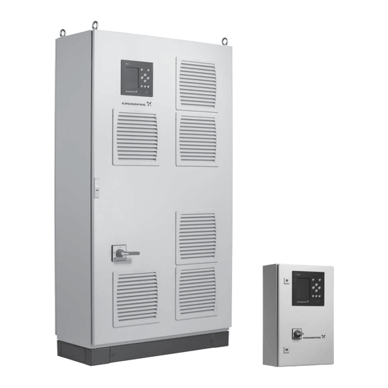
    Die Control MPC lässt sich entsprechend der Steuerungsvariante Abb. 1 Control MPC in fünf Gruppen einteilen: 5.1 Produktbeschreibung Steuerung- Die Grundfos Control MPC wird hauptsächlich zur Steuerung und Beschreibung svariante Überwachung von Druckerhöhungsanlagen und Umwälzsyste- men eingesetzt. 2 bis 6 Pumpen mit integriertem Frequenzumrich- ter (0,37-22 kW).
  • Seite 78: Produktidentifikation

    DK - 8850 - Bjerringbro - Denmark * Gilt nur für Druckerhöhungsanlagen Abb. 2 Typenschild ** Gilt nur für CR-, CRI-, CRN-, CRE- und CRIE-Pumpen Pos. Beschreibung Eine GSC-Datei (Grundfos Standard Configuration) Produkttyp ist eine Datei mit Konfigurationsdaten. Modellcode Netzversorgung Bestell-Nr. Bemessungsstrom [A] Bedingter Bemessungskurzschlussstrom [kA] Maximale Umgebungstemperatur [°C]...
  • Seite 79 5.3.3 Typenschlüssel Code Beispiel Control MPC 000A direkt Baureihe Anlagenart Alle Pumpen mit E-Motor Alle Pumpen mit CUE-Frequenzumrichter Pumpe mit fester Drehzahl, 1 CUE Alle Frequenzumrichter, außer CUE Pumpen mit fester Drehzahl Serie 2000 Anzahl der Hauptpumpen Hauptpumpenstrom Anlaufmethode Elektronisch direkt Direktanlasser Sterndreiecksanlasser...
  • Seite 80 • CIM 110 LonWorks-Modul • CIM 150 PROFIBUS DP-Modul • CIM 200 Modbus RTU-Modul Im Schalt- schrank 3G/4G GRM Grundfos Remote Manage- • CIM 260 ment 3G/4G GRM Grundfos Remote Manage- • CIM 280 ment • CIM 300 BACnet MS/TP-Modul •...
  • Seite 81 Im vordefinierten Control MPC- Bedienfeldoptionen Standard enthalten Optionen (Typen- Aufstel- optional Beschreibung schlüssel lungsort für Con- trol MPC) Im Schaltschrank montiertes Elektroden- Trockenlauf- relais. Im Schalt- schutz - Elektro- ● Hinweis: Elektroden müssen separat schrank denrelais bestellt werden. Der Vibrationsgrenzschalter ist im Schalt- Trockenlauf- bild sichtbar.
  • Seite 82 Im vordefinierten Control MPC- Bedienfeldoptionen Standard enthalten Optionen (Typen- Aufstel- optional Beschreibung schlüssel lungsort für Con- trol MPC) Die Schaltschrankbeleuchtung leuchtet, wenn die Schaltschranktür geöffnet ist. Die Schaltschrankbeleuchtungen für 50 Schaltschrankbe- Hz entsprechen den Anforderungen nach Im Schalt- leuchtung und EN 60529/10.91.
  • Seite 83: Übersicht Über Die Steuerungsvarianten

    Control MPC mit drei Pumpen, die an EC: Control MPC mit drei Pumpen, die einen gemeinsamen CUE-Frequenzum- Control MPC mit drei ungeregelten Pum- jeweils an einen eigenen CUE-Frequenz- richter von Grundfos angeschlossen sind. pen. umrichter von Grundfos angeschlossen Die Pumpen werden abwechselnd dreh- sind.
  • Seite 84 Das nachfolgend aufgeführte Beispiel gilt für Umwälzsysteme. 7. Bedienfeld Das Bedienfeld an der Vorderseite des Schaltschranks besteht Control MPC Serie 2000 aus einem Display, mehreren Tasten und zwei Meldeleuchten. Control MPC mit drei E-Pumpen. Das Bedienfeld ermöglicht das manuelle Einstellen und das Überwachen der Leistung der Anlage.
  • Seite 85: Bedientasten Und Meldeleuchten

    7.1 Anzeige 7.2 Bedientasten und Meldeleuchten Die Bedientasten (2 bis 10 in Abb. 4) an der CU 352 sind dann aktiv, wenn sie beleuchtet sind. 7.2.1 Pfeil nach rechts (2) Drücken Sie auf [Pfeil nach rechts], um innerhalb der Menüstruk- tur zum nächsten Menü...
  • Seite 86: Betrieb

    8. Funktionen 8.1 Funktionsverzeichnis Die verfügbaren Funktionen sind von der Anlagenkonfiguration abhängig. 1. Status 2. Betrieb 3. Alarm Fortsetzung auf Seite 1. Status 2. Betrieb 3. Alarmstatus Aktuelle Alarme Weitere Einstellungen 3.1 Aktuelle Alarme Anlage 2.1.1 Anlagenbetriebsart 3.2 Alarmspeicher 1.2.1 Betriebsart 2.1.2 Regelungsart 3.3 Service Kontaktinformationen 1.2.2 Sollwert...
  • Seite 87 Fortsetzung von Seite 4. Einstellung 1 -> Primärsteuerung 4.1.1 PI-Regler 4.1.2 Alternative Sollwerte 4.1.2.1 Alternative Sollwerte 2-7 4.1.3 Externe Sollwertführung 4.1.3.1 Messgröße geführt durch 4.1.3.2 Einstellen des ext. Sollwerteinflusses 4.1.4 Sensor, druckseitig 4.1.5 Sekundärsensor 4.1.6 Zeitprogramm 4.1.7 Proportionaldruck 4.1.8 Konfiguration S-Anlage 4.1.9 Sollwertrampe Pumpenkaskadensteuerung...
  • Seite 88 8.2 Übersicht Abschnitt Bildschirmseite und Bildschirmnummer Seite 8.4 Status (1) 8.4.1 8.4.1 Aktuelle Alarme (3.1) 8.4.2 8.4.2 Anlage (1.2) 8.4.3 8.4.3 Betriebsart (1.2.1) 8.4.4 8.4.4 Sollwert (1.2.2) 8.4.5 8.4.5 Sollwertverschiebung (1.2.3) 8.4.6 8.4.6 Messwerte (1.2.4) 8.4.7 8.4.7 Analogeingänge (1.2.5) 8.4.8 8.4.8 Kurve aufzeichnen (1.2.6) 8.4.9 Batteriezustand (1.2.7)
  • Seite 89 Abschnitt Bildschirmseite und Bildschirmnummer Seite 8.7.32 8.7.32 Messgrößen Analogeingänge (4.3.8.1.1 - 4.3.8.7.1) 8.7.33 8.7.33 Digitalausgänge (4.3.9) 8.7.34 8.7.34 Funktionen Digitalausgänge (4.3.9.1 - 4.3.9.16) 8.7.35 8.7.35 Analogausgänge (4.3.10) 8.7.36 8.7.36 Ausgangssignal (4.3.10.1 - 4.3.10.3) 8.7.38 8.7.38 Min.-, Max.- und benutzerdefinierter Betrieb (4.3.14) 8.7.39 8.7.39 Min.-Betrieb (4.3.14.1) 8.7.40...
  • Seite 90: Beschreibung Der Funktionen

    8.3 Beschreibung der Funktionen In der Mitte des Bildschirms wird ein Informationsfeld (I) ange- zeigt, falls eines der folgenden Ereignisse eintritt: Die Beschreibung der Funktionen bezieht sich auf die vier Haupt- • Eingeschr. Betr. wg. Reservepumpe menüs der Steuereinheit CU 352: •...
  • Seite 91 8.4.1 Aktuelle Alarme (3.1) 8.4.3 Betriebsart (1.2.1) Abb. 7 Aktuelle Alarme Abb. 9 Betriebsart Beschreibung Beschreibung Auf dieser Bildschirmseite werden aktive, noch nicht quittierte Auf dieser Bildschirmseite wird angezeigt, auf welche Betriebsart Alarm- und Warnmeldungen angezeigt. die Anlage eingestellt ist und von wo aus die Anlage gesteuert wird.
  • Seite 92 8.4.4 Sollwert (1.2.2) Zuletzt wird der aus der Sollwertverschiebung resultierende aktu- elle Sollwert (SOLL) angezeigt. 8.4.6 Messwerte (1.2.4) Abb. 10 Sollwert Beschreibung Abb. 12 Messwerte Auf dieser Bildschirmseite wird der ausgewählte Sollwert ange- zeigt und angegeben, ob dieser von der CU 352 oder einem Beschreibung externen Bus vorgegeben wird.
  • Seite 93 8.4.8 Kurve aufzeichnen (1.2.6) 8.4.10 Pumpe 1-6, Pilotpumpe (1.3 - 1.10) Abb. 14 Kurve aufzeichnen Abb. 16 Pumpe 1 Beschreibung Beschreibung Auf dieser Bildschirmseite werden die von der Steuerung erfass- Auf dieser Bildschirmseite wird der Betriebszustand der einzel- ten Daten angezeigt. Die aufzuzeichnenden Werte können Sie nen Pumpen angezeigt.
  • Seite 94 8.5 Betrieb (2) Werkseinstellung Der Sollwert ist auf einen für die vorliegende Anlage typischen In diesem Menü können die grundlegenden Parameter wie Soll- Wert eingestellt. Die Werkseinstellung kann über das Inbetrieb- wert, Betriebsart, Regelungsart und Parameter zur Regelung von nahmemenü geändert worden sein. einzelnen Pumpen eingestellt werden.
  • Seite 95 8.5.3 Regelungsart (2.1.2) Einstellungen über das Bedienfeld • Betrieb > Weitere Einstellungen > Regelungsart > Geregelt. Stellen Sie den Sollwert ein. Siehe Abschnitte 8.5.4 Alternative Sollwerte (2.1.3) 8.5.1 Betrieb (2). Ungeregelt Im ungeregelten Betrieb laufen die Pumpen mit einer festen Drehzahl.
  • Seite 96 Einstellungen über das Bedienfeld Förderstrom [m Um eine externe Steuerquelle zum Steuern der Anlage auszu- wählen, gehen Sie wie folgt vor: • Betrieb > Weitere Einstellungen > Regelungsart. • Wählen Sie Folgendes aus: Ungeregelt. 1. Drücken Sie 2 x die Taste [Zurück]. Durchfluss- menge 2.
  • Seite 97 8.5.4 Alternative Sollwerte (2.1.3) 8.5.5 Steuerung einzelner Pumpen (2.1.4) Abb. 27 Alternative Sollwerte Abb. 28 Steuerung einzelner Pumpen Beschreibung Beschreibung Neben dem Hauptsollwert 1 (im Menü "Betrieb" auf der Bild- Die Betriebsart kann vom automatischen Betrieb auf eine der schirmseite 2 angezeigt) können sechs alternative Sollwerte für manuellen Betriebsarten geändert werden.
  • Seite 98 8.5.6 Pumpe 1-6 (2.1.4.1 - 2.1.4.6) 8.5.7 Steuerung Pilotpumpe (2.1.4.7) Abb. 29 Pumpe 1-6 Abb. 30 Steuerung Pilotpumpe Beschreibung Beschreibung Diese Bildschirmseite wird für jede einzelne Pumpe angezeigt. Diese Bildschirmseite wird nur angezeigt, wenn die Anlage mit Sie ermöglicht das Einstellen der Betriebsart für die einzelnen einer Pilotpumpe ausgerüstet ist und entsprechend konfiguriert Pumpen.
  • Seite 99 8.6 Alarm (3) In diesem Menü werden alle Alarm- und Warnmeldungen ange- zeigt. Hier können auch Alarme quittiert werden. 8.6.1 Alarmstatus (3) Abweichende Sen- automa- Warnung sorsignale tisch Störung, druckseiti- automa- Alarm Stopp ger Sensor tisch automa- Sensorstörung Warnung tisch Kommunikations- automa- Warnung...
  • Seite 100 8.6.2 Aktuelle Alarme (3.1) 8.6.3 Alarmspeicher (3.2) Im Alarmspeicher können bis zu 24 Warnungen und Alarme gespeichert werden. Abb. 32 Aktuelle Alarme Beschreibung Abb. 33 Alarmspeicher Das Untermenü auf der Bildschirmseite "Alarm" zeigt Folgendes Beschreibung • Warnungen , die durch Störungen ausgelöst wurden, die noch Auf dieser Bildschirmseite werden die Warnungen und Alarme akut sind.
  • Seite 101 8.7 Einstellung (4) 8.7.1 Primärsteuerung (4.1) Abb. 36 Primärsteuerung Abb. 35 Einstellung Beschreibung Im Menü "Einstellungen" können die folgenden Funktionen einge- stellt werden: In diesem Menü können die Funktionen für den primären Regler eingestellt werden. Einstellungen in diesem Menü sind nur erfor- •...
  • Seite 102 8.7.2 PI-Regler (4.1.1) Einstellung des PI-Reglers für Heizung und Kühlung Wurde beim Durchlaufen des Inbetriebnahmeassistenten eine andere Anwendung als Druckerhöhung gewählt, werden Kp und Ti automatisch auf die in der nachfolgenden Tabelle aufgeführten Werte gesetzt. Da der Anlage die Rohrleitungslänge nicht bekannt ist, werden die Werte standardmäßig für eine Rohrlei- tungslänge (L1 oder L2) von 5 m ausgewählt.
  • Seite 103 8.7.3 Alternative Sollwerte (4.1.2) 8.7.4 Alternative Sollwerte 2-7 (4.1.2.1 - 4.1.2.7) Abb. 38 Alternative Sollwerte Abb. 39 Alternative Sollwerte 2-7 Beschreibung Wählen Sie für jeden alternativen Sollwert den Digitaleingang für die Aktivierung des Sollwerts aus. Mithilfe dieser Funktion können bis zu sechs Sollwerte (Sollwert 2 bis 7) als Alternative zum Hauptsollwert (Sollwert 1) ausgewählt Für den geregelten und den ungeregelten Betrieb kann jeweils werden.
  • Seite 104 8.7.5 Externe Sollwertführung (4.1.3) Einstellungen über das Bedienfeld • Einstellung > Primärsteuerung > Externe Sollwertführung > Messgröße geführt durch. Es wird eine Liste der verfügbaren Parameter angezeigt. 1. Wählen Sie den Parameter aus, der den Sollwert verschieben soll. 2. Drücken Sie auf die Taste [Zurück]. 3.
  • Seite 105 8.7.6 Einstellen des ext. Sollwerteinflusses (4.1.3.2) 8.7.7 Sensor, druckseitig (4.1.4) Abb. 43 Sensor, druckseitig Abb. 41 Einstellen des ext. Sollwerteinflusses Beschreibung Beschreibung Auf dieser Bildschirmseite werden der Regelparameter der Hier kann das Verhältnis zwischen dem Messparameter, über den Anlage ausgewählt und der Sensor zum Messen des Parameters der Sollwert angepasst werden soll, und der erforderlichen Füh- eingestellt.
  • Seite 106 8.7.8 Sekundärsensor (4.1.5) Beschreibung Mithilfe dieser Funktion können Sollwerte eingestellt sowie Zeit und Datum für ihre Aktivierung vorgeben werden. Darüber hinaus können Sie Zeit und Datum für die Abschaltung der Anlage einge- ben. Der vom Programm vorgegebene Sollwert bleibt aktiv, wenn das Zeitprogramm deaktiviert wird.
  • Seite 107 8.7.10 Proportionaldruck (4.1.7) Einstellbereich • Auswählen der Regelungsart • Verschiebung bei Nullförderung • Abgeschätzter Volumenstrom • Filterfaktor. Einstellungen über das Bedienfeld • Einstellung > Primärsteuerung > Proportionaldruck. 1. Wählen Sie Folgendes aus: Aktiviert. 2. Wählen Sie Folgendes aus: • Anpassung •...
  • Seite 108 8.7.11 Konfiguration S-Anlage (4.1.8) 8.7.12 Sollwertrampe (4.1.9) Abb. 49 Konfiguration S-Anlage Abb. 51 Sollwertrampe Beschreibung Beschreibung Diese Funktion ermöglicht es, die Regelung von ungeregelten Ist diese Funktion aktiviert, erfolgt die Änderung des Sollwerts Pumpen (MPC-S) umzukehren. Das bedeutet, Sie können ein- schrittweise über einen gewissen Zeitraum entlang einer Soll- stellen, ob Pumpen in Abhängigkeit vom aktuellen Wert einge- wertrampe.
  • Seite 109 8.7.13 Pumpenkaskadensteuerung (4.2) 8.7.15 Max. Anzahl Einschaltungen/Stunde (4.2.1) Abb. 52 Pumpenkaskadensteuerung Abb. 54 Max. Anzahl Einschaltungen/Stunde In diesem Menü können die Funktionen in Bezug auf die Pum- Beschreibung penkaskadensteuerung eingestellt werden. Durch diese Funktion wird die Anzahl der Pumpeneinschaltungen Folgende Untermenüs können ausgewählt werden: und -abschaltungen pro Stunde für die gesamte Anlage begrenzt.
  • Seite 110 8.7.16 Reservepumpen (4.2.3) 8.7.17 Erzwungener Pumpentausch (4.2.4) Abb. 55 Reservepumpen Abb. 56 Erzwungener Pumpentausch Beschreibung Beschreibung Mithilfe dieser Funktion kann die maximale Anlagenleistung Diese Funktion sorgt dafür, dass alle Pumpen die gleiche Anzahl begrenzt werden, indem eine oder mehrere Pumpen als Reserve- an Betriebsstunden laufen.
  • Seite 111 8.7.18 Testlauf (4.2.5) 8.7.19 Pumpenabschaltversuch (4.2.7) Abb. 57 Testlauf Abb. 58 Pumpenabschaltversuch Beschreibung Beschreibung Diese Funktion wird hauptsächlich verwendet, wenn der erzwun- Diese Funktion ermöglicht das Festlegen von automatischen gene Pumpenwechsel deaktiviert ist und/oder wenn die Anlage Abschaltversuchen einer Pumpe, wenn mehrere Pumpen gleich- auf die Betriebsart "Stopp"...
  • Seite 112 8.7.20 Ein- und Abschaltdrehzahl der Pumpen (4.2.8) Einstellungen über das Bedienfeld • Einstellung > Pumpenkaskadensteuerung > Ein- und Beschreibung Abschaltdrehzahl der Pumpen. Mithilfe dieser Funktion wird das Ein- und Ausschalten von Pum- • Wählen Sie Folgendes aus: Feste Drehzahl verwenden. pen geregelt.
  • Seite 113 8.7.22 Kompensation der Pumpenanlaufzeit (4.2.10) 8.7.23 Weitere Funktionen (4.3) Abb. 62 Kompensation der Pumpenanlaufzeit Abb. 63 Weitere Funktionen Beschreibung Beschreibung Diese Funktion wird nur in Verbindung mit MPC-F-Anlagen ver- Auf dieser Bildschirmseite können Funktionen eingestellt werden, wendet. die für den normalen Betrieb der Anlage sekundär sind. "Weitere Funktionen"...
  • Seite 114 8.7.24 Stoppfunktion (4.3.1) A: Normalbetrieb B: Druckerhöhung C: Stopp Stopp: HSoll + 0,5 x EIN/AUS-Druckband Einschalten: HSoll - 0,5 x EIN/AUS-Druckband Abb. 66 EIN/AUS-Betrieb Abb. 64 Stoppfunktion Der Förderstrom wird von der Steuerung CU 352 geschätzt, wenn sich die Pumpe in der Ausschaltphase befindet. Solange der För- Beschreibung derstrom niedriger als Qmin ist, läuft die Pumpe im EIN/AUS- Diese Funktion wird in der Regel bei Konstantdruckanwendungen...
  • Seite 115 Sind sowohl ein Durchflussmesser als auch ein Strömungsschal- Beispiel 1: Erhöhen des Abschaltgrenzwerts Qmin (hoher ter angeschlossen, wird der Wechsel auf EIN/AUS-Betrieb durch Förderstromgrenzwert) das Gerät aktiviert, das zuerst einen geringen Förderstrom • Erhöhen Sie "Druckbereich für den Gradienten". anzeigt. •...
  • Seite 116 Anlage mit Strömungsschalter Werkseinstellung Nehmen Sie die folgenden zusätzlichen Einstellungen vor: Diese Funktion ist bei Druckerhöhungsanwendungen aktiviert. Werkseitig sind die in der Tabelle aufgeführten Werte eingestellt. 1. Wählen Sie Folgendes aus: Digitaleingang parametrieren. Die Bildschirmseite 8.7.28 Digitaleingänge (4.3.7) wird aufgeru- EIN/AUS-Druckband: 25 % fen.
  • Seite 117 Einstellungen über das Bedienfeld Einstellbereich • Einstellung > Weitere Funktionen > Pilotpumpe. • Pumpendrehzahl 1. Pilotpumpe aktivieren • Anzahl der Pumpen – Stellen Sie Folgendes ein: Wechsel zu Pilotpumpe • Fülldruck – Stellen Sie Folgendes ein: Zeit Hysterese • Maximale Füllzeit –...
  • Seite 118 8.7.27 Notbetrieb (4.3.5) 8.7.28 Digitaleingänge (4.3.7) Abb. 75 Notbetrieb Abb. 76 Digitaleingänge Beschreibung Beschreibung Diese Funktion wird bei Druckerhöhungsanwendungen verwen- In diesem Menü können die Digitaleingänge der CU 352 einge- det. Ist diese Funktion aktiviert, laufen die Pumpen weiter, auch stellt werden.
  • Seite 119: Kontaktaktivierung

    8.7.29 Funktionen Digitaleingänge (4.3.7.1) Werkseinstellung Digitaleingang Funktion Externes Ein-/Ausschalten. Offener Kontakt DI1 (CU 352) [10] = AUS. Hinweis: Eingang Nr. 1 kann nicht geändert werden. Überwachung des Wassermangels (Tro- ckenlaufschutz). Offener Kontakt = Wasser- DI2 (CU 352) [12] mangel (falls die Anlage mit dieser Option ausgestattet ist).
  • Seite 120 8.7.31 Analogeingänge (4.3.8.1 - 4.3.8.7) 8.7.32 Messgrößen Analogeingänge (4.3.8.1.1 - 4.3.8.7.1) Abb. 79 Analogeingänge Abb. 80 Messgrößen Analogeingänge Beschreibung Beschreibung In diesem Menü können Sie Einstellungen für "Analogeingänge" Auf diesen Bildschirmseiten kann den einzelnen Analogeingän- festlegen. Jede Bildschirmseite ist in drei Bereiche unterteilt: gen eine Funktion zugeordnet werden.
  • Seite 121 8.7.33 Digitalausgänge (4.3.9) Einstellbereich Sie können je Bildschirmseite eine Funktion auswählen: • Nicht aktiviert • Betrieb, Anlage • Alarm, Anlage • Warnung, Anlage • Bereit, Anlage • Wassermangel • Min. Druck • Max. Druck • Notbetrieb • Steuerung Pilotpumpe • Druckentlastungsventil •...
  • Seite 122 8.7.36 Ausgangssignal (4.3.10.1 - 4.3.10.3) 8.7.37 Zählereingänge (4.3.11) Abb. 84 Ausgangssignal Abb. 85 Zählereingänge Beschreibung Beschreibung Auf dieser Bildschirmseite können die nachfolgenden Parameter Hier kann eingestellt werden, dass die CU 352 die von einem ausgewählt werden. digitalen Wasserzähler gemessene Fördermenge aufsummiert. Einstellbereich Einstellungen über das Bedienfeld •...
  • Seite 123 8.7.39 Min.-Betrieb (4.3.14.1) 8.7.40 Max.-Betrieb (4.3.14.2) Abb. 87 Min.-Betrieb Abb. 88 Max.-Betrieb Beschreibung Beschreibung Bei allen Anlagen, mit Ausnahme von MPC-S-Anlagen, können Bei Aktivierung der Funktion kann eine festzulegende Anzahl an nur die drehzahlgeregelten Pumpen in der Betriebsart "Min.- Pumpen mit maximaler Leistung laufen. Betrieb"...
  • Seite 124 (P1) eingegeben werden. • Anlagendrehzahl. Die erforderlichen Daten können den Pumpenkennlinien entnom- Werkseinstellung men werden. Diese finden Sie im Grundfos Product Center auf Die Funktion ist deaktiviert, da Folgendes eingestellt wurde: der Grundfos-Website www.grundfos.com. Siehe die Beispiele in Abb. bis 91.
  • Seite 125 CRIE) manuell ein. Für E-Pumpen von Grundfos muss auch die Aufnah- meleistung (P1) eingegeben werden. Die erforderlichen Daten können den Pumpenkennlinien entnom- men werden. Diese finden Sie im Grundfos Product Center auf der Grundfos-Website www.grundfos.com. Siehe die Beispiele in Abb. bis 95.
  • Seite 126 Werkseinstellung Als Steuerquelle ist die CU 352 eingestellt. 8.7.46 Konstanter Vordruck (4.3.22) Bemessungsleistung PBem Abb. 95 Ablesen der Bemessungsleistung PBem (Grundfos Product Center) QBem und HBem bilden den Bemessungsbetriebs- punkt der Pumpen. Dies ist in der Regel der Betriebspunkt mit dem besten Wirkungsgrad.
  • Seite 127 8.7.47 Förderstromabschätzung (4.3.23) 8.7.48 Reduzierter Betrieb (4.3.24) Abb. 98 Förderstromabschätzung Abb. 99 Reduzierter Betrieb Beschreibung Beschreibung Wie in Abschnitt 8.7.43 Pumpenkennliniendaten (4.3.19) Mithilfe dieser Funktion kann die Anzahl der Pumpen in Betrieb beschrieben kann die CU 352 den Betrieb entsprechend den oder, bei MPC-E-Anlagen, die Leistungsaufnahme begrenzt wer- Kennlinien- und Motordaten optimieren.
  • Seite 128 8.7.49 Einstellungen Mehrzwecksensor (4.3.25) Einstellungen über das Bedienfeld • Einstellung > Weitere Funktionen > Einstellungen Mehrzweck- sensor. 1. Wählen Sie Folgendes aus: Aktivieren. 2. Stellen Sie Folgendes ein: Anzahl an Sensoren 3. Stellen Sie Folgendes ein: Sollwert-Grenzwerte (Wählen Sie Folgendes aus: Minimum und Maximum). 4.
  • Seite 129 8.7.51 Überwachungsfunktionen (4.4) 8.7.52 Trockenlaufschutz (4.4.1) Abb. 102Überwachungsfunktionen Abb. 103Trockenlaufschutz Beschreibung Beschreibung Die Anlage verfügt über eine Reihe von Funktionen, die den Der Trockenlaufschutz gehört zu den wichtigsten Überwachungs- Betrieb der Anlage kontinuierlich überwachen. funktionen, da die Lager und die Wellendichtung beschädigt wer- den können, wenn die Pumpen trocken laufen.
  • Seite 130 8.7.53 Druck-/Niveauschalter (digital) (4.4.1.1) 8.7.54 Messung, Vordruck (analog) (4.4.1.2) Abb. 104Druck-/Niveauschalter (digital) Abb. 105Messung, Vordruck (analog) Beschreibung Beschreibung Diese Funktion wird hauptsächlich bei Druckerhöhungsanwen- Der Trockenlaufschutz kann über einen Druckgeber realisiert dungen verwendet. Der Trockenlaufschutz kann über einen werden, der den Eingangsdruck misst. Druckschalter am Sammelrohr auf der Zulaufseite oder über Es können zwei Füllstände eingegeben werden: einen Niveauschalter in einem Behälter auf der Zulaufseite reali-...
  • Seite 131 8.7.55 Messung, Füllstand Vorlaufbehälter (analog) (4.4.1.3) 8.7.56 Min. Druck (4.4.2) Abb. 106Messung, Füllstand Vorlaufbehälter (analog) Abb. 107Min. Druck Beschreibung Beschreibung Der Trockenlaufschutz kann über einen Niveaugeber realisiert Bei Druckerhöhungsanwendungen wird der Ausgangsdruck über- werden, der den Füllstand in einem Behälter auf der Zulaufseite wacht.
  • Seite 132 8.7.57 Max. Druck (4.4.3) 8.7.58 Externe Störung (4.4.4) Abb. 108Max. Druck Abb. 109Externe Störung Beschreibung Beschreibung Bei Druckerhöhungsanwendungen wird der Ausgangsdruck über- Diese Funktion wird verwendet, damit die CU 352 eine Störmel- wacht. Bei allen anderen Anwendungen wird der Systemdruck dung von einem externen Kontakt erhalten kann.
  • Seite 133 8.7.59 Überschreitung Grenzwert 1 (4.4.5 - 4.4.6) Einstellungen über das Bedienfeld Die Analogeingänge müssen korrekt eingestellt sein, bevor die Funktion aktiviert wird. Siehe Abschnitt 8.7.30 Analogeingänge (4.3.8). • Einstellung > Überwachungsfunktionen > Überschreitung Grenzwert 1 / Überschreitung Grenzwert 2 > Analogeingang parametrieren.
  • Seite 134 8.7.60 Pumpen außerhalb des Betriebsbereichs (4.4.7) 8.7.61 Druckentlastung (4.4.8) Abb. 111Pumpen außerhalb des Betriebsbereichs Abb. 112Druckentlastung Beschreibung Beschreibung Die Funktion gibt eine Warnmeldung aus, wenn der Betriebspunkt Die Funktion dient dazu, den Druck in den Rohrleitungen durch außerhalb des vorgegebenen Bereichs liegt, z. B. wenn der Ein- Öffnen eines Magnetventils zu reduzieren, wenn ein voreinge- gangsdruck unter einen zulässigen Mindestwert absinkt und stellter Grenzwert überschritten wird.
  • Seite 135 Einstellungen über das Bedienfeld 8.7.63 Störung, Hauptsensor (4.4.10) • Einstellung > Überwachungsfunktionen > Druckentlastung > Digitalausgang parametrieren. 1. Wählen Sie den Digitalausgang aus. 2. Wählen Sie Folgendes aus: Druckentlastungsventil. 3. Drücken Sie 2 x die Taste [Zurück]. 4. Wählen Sie Folgendes aus: Zu überwachender Druck •...
  • Seite 136 8.7.64 Rückschlagventil (4.4.11) 8.7.65 Funktionen CU 352 (4.5) Abb. 116Rückschlagventil Abb. 117Funktionen CU 352 Beschreibung Beschreibung Mithilfe dieser Funktion kann die CU 352 erkennen, ob eine In diesem Untermenü können Sie die grundlegenden Einstellun- Leckage oder eine Störung an einem "Rückschlagventil" vorliegt. gen für die CU 352 vornehmen.
  • Seite 137 8.7.66 Displaysprache (4.5.1) 8.7.67 Maßeinheiten (4.5.2) Abb. 118Displaysprache Abb. 119Maßeinheiten Beschreibung Beschreibung Hier können Sie die Displaysprache für die CU 352 auswählen. Auf dieser Bildschirmseite können die Maßeinheiten für die ver- schiedenen Parameter ausgewählt werden. Einstellbereich Sie können zwischen SI- und imperialen Einheiten auswählen. •...
  • Seite 138 Einstellungen über das Bedienfeld 8.7.68 Datum und Uhrzeit (4.5.3) • Einstellung > Funktionen CU 352 > Maßeinheiten. Wählen Sie das Einheitensystem aus und ändern Sie ggf. für die einzelnen Messparameter die Maßeinheit. Siehe Beispiel in Abb. 120. Abb. 121Datum und Uhrzeit Beschreibung Auf dieser Bildschirmseite können die Uhrzeit und das Datum ein- gestellt sowie das Anzeigeformat festgelegt werden.
  • Seite 139 Bussignal eingestellt werden. Außerdem können der Status wich- tiger Parameter, wie z. B. der aktuelle Wert und die Leistungsauf- nahme, sowie Störmeldungen an der CU 352 abgelesen werden. Wenden Sie sich bitte an Grundfos, um weitere Informationen zu erhalten. Einstellbereich Die GENIbus-Adresse kann auf eine Zahl zwischen 1 und 64 ein- gestellt werden.
  • Seite 140 1. Wählen Sie Anzeige 1, 2 oder 3 aus und drücken Sie die Taste kann die Softwareversion aktualisiert werden. Wenden Sie sich [OK]. bitte an Grundfos, um weitere Informationen zu erhalten. 2. Legen Sie eine Bezeichnung für die Anzeige fest. 8.7.73 Statusanzeigemenü (4.6) 3.
  • Seite 141 Die CU 352 ist mit einer Hardware ausgestattet, die die Kommunikation mit externen Geräten, wie z. B. einem Computer, über eine externe GENIbus- oder Ethernet-Verbindung ermöglicht. CIU- Gateway Kommunikation Internet sschnittstelle anderen Intranet von Grundfos Anbietern Außendurchmesser Externe GENIbus- GENIbus-Modul Verbindung (optional) Ethernet-Anschluss Abb. 128Datenkommunikation über externe GENIbus- und Ethernet-Verbindung 8.8.1 Ethernet...
  • Seite 142 Siehe Beispiele in Abb. 128. Für weitere Informationen wenden Sie sich bitte an Grundfos. Als Gateway kann ein CIU-Kommunikationsschnittstellengerät von Grundfos oder ein Gateway eines anderen Anbieters verwendet werden. Weitere Informationen zum CIU finden Sie im Grundfos Product Center oder erhalten Sie direkt bei Grundfos.
  • Seite 143: Servicearbeiten Am Produkt

    Die Stromversorgung ist unterbrochen. Stellen Sie die Stromversorgung her. Ein Neustart ist nicht möglich. Die CU 352 ist defekt. Bitte wenden Sie sich an Grundfos. Die Stromversorgung ist unterbrochen. Stellen Sie die Stromversorgung her. Der Hauptschalter ist ausgeschaltet. Schalten Sie den Hauptschalter ein.
  • Seite 144: Außerbetriebnahme Des Produkts

    11. Außerbetriebnahme des Produkts Eingänge für PTC-Sensor/Thermoschalter Für Kaltleiter nach DIN 44082. Es können auch Thermoschalter Schalten Sie den Hauptschalter aus, um die Anlage außer angeschlossen werden. Betrieb zu nehmen. Leerlaufspannung: 12 V DC ±15 % WARNUNG Ruhestrom: 2,6 mA, DC Stromschlag Tod oder ernsthafte Personenschäden - Berühren Sie nicht die Leiter vor dem Hauptschal-...
  • Seite 145: Mitgeltende Dokumentation

    1. Nutzen Sie die öffentlichen oder privaten Entsorgungs- gesellschaften. Abb. 134Druckerhöhung 2. Ist das nicht möglich, wenden Sie sich bitte an eine Grundfos- Niederlassung oder eine von Grundfos anerkannte Service- werkstatt in Ihrer Nähe. Das Symbol mit einer durchgestrichenen Mülltonne weist darauf hin, dass das jeweilige Produkt nicht im Haushaltsmüll entsorgt werden darf.
  • Seite 146 Estas instrucciones de instalación y funcionamiento describen la 1.1 Indicaciones de peligro gama Control MPC de Grundfos. Las instrucciones de instalación y funcionamiento, instrucciones CONTENIDO de seguridad e instrucciones de mantenimiento de Grundfos pue- den contener los siguientes símbolos e indicaciones de peligro. Página Información general PELIGRO Indicaciones de peligro Indica una situación peligrosa que, de no reme-...
  • Seite 147: Recepción Del Producto

    8. Ahora, el sistema estará preparado para funcionar. Fig. 1 Izado correcto del cuadro de control Grundfos puede suministrar datos hidráulicos para Use un equipo de izado adecuado que se encuentre en buen las bombas CR, CRI, CRN, CRE y CRIE, y los archi- estado y esté...
  • Seite 148: Introducción De Producto

    El cuadro Control MPC se divide en cinco grupos en función de la variante de control: 5.1 Descripción del producto El cuadro Control MPC de Grundfos se utiliza principalmente Variante de para controlar y monitorizar sistemas de aumento de presión y de Descripción...
  • Seite 149 ** Se aplica únicamente a las bombas CR, CRI, CRN, CRE y Pos. Descripción CRIE. Tipo de producto Código de modelo Los archivos de configuración estándar de Grundfos Alimentación principal (GSC, por las siglas en inglés) son archivos de datos de configuración. N.º de pedido Corriente nominal [A] Corriente nominal de cortocircuito [kA] Temperatura ambiente máxima [°C]...
  • Seite 150 5.3.3 Nomenclatura Cód. Ejemplo Control MPC 000A DOL Gama Tipo de sistema Todas las bombas con motor E Todas las bombas con variador de frecuencia CUE Bombas de velocidad fija y un variador de frecuencia CUE Todas las bombas con variador de frecuencia (que no sea un variador CUE) Bombas de velocidad fija Serie 2000...
  • Seite 151 Módulo LonWorks • CIM 150 Módulo PROFIBUS DP • CIM 200 Módulo Modbus RTU Interior del cuadro de Sistema de gestión remota de Grundfos control • CIM 260 (GRM) 3G/4G Sistema de gestión remota de Grundfos • CIM 280 (GRM) 3G/4G •...
  • Seite 152 Incluida de serie en las versiones Opciones del panel de control estándar del cua- dro Control MPC Opciones (código del Opción Descripción Ubicación cuadro Control MPC) Protección contra El panel incorpora un relé de electrodo. Interior del marcha en seco, relé Nota: Los electrodos deben pedirse por cuadro de ●...
  • Seite 153 Incluida de serie en las versiones Opciones del panel de control estándar del cua- dro Control MPC Opciones (código del Opción Descripción Ubicación cuadro Control MPC) La luz del panel se enciende cuando la puerta del cuadro de control está abierta.
  • Seite 154 CUE • La conmutación de las bombas es auto- de Grundfos. Si la bomba no puede man- • La conmutación de las bombas es auto- mática y depende de la carga, las horas tener la presión, se activarán una o dos...
  • Seite 155: Panel De Control

    El ejemplo mostrado a continuación está basado en un sistema 7. Panel de control de circulación. El panel de control de la cubierta delantera del cuadro de control presenta una pantalla, una serie de botones y dos indicadores Cuadro Control MPC Serie 2000 luminosos.
  • Seite 156 7.1 Pantalla 7.2 Botones e indicadores luminosos Los botones (pos. 2-10 en la fig. 4) de la unidad CU 352 se encuentran activos cuando están iluminados. 7.2.1 Intro (2) Pulse [Intro] para acceder al siguiente menú en la estructura de menús.
  • Seite 157 8. Funciones 8.1 Árbol de funciones Las funciones dependen de la configuración del sistema. 1. Estado 2. Funcionam. 3. Alarma Continúa en la página 1. Estado 2. Funcionam. 3. Estado de alarma Alarmas actuales Ajustes adicionales 3.1 Alarmas actuales Sistema 2.1.1 Modo de funcionamiento del 3.2 Registro de 1.2.1 Modo funcionam.
  • Seite 158 Continúa de la página 4. Ajustes 1 -> Controlador principal 4.1.1 Controlador PI 4.1.2 Puntos de ajuste alternativos 4.1.2.1 Puntos de ajuste alternativos 2-7 4.1.3 Influencia punto ajus. ext. 4.1.3.1 Valor de entrada que influirá 4.1.3.2 Ajuste de la función de influencia 4.1.4 Sensor principal 4.1.5...
  • Seite 159 8.2 Resumen Sección Pantalla y número de pantalla Página 8.4 Estado (1) 8.4.1 8.4.1 Alarmas actuales (3.1) 8.4.2 8.4.2 Sistema (1.2) 8.4.3 8.4.3 Modo funcionam. (1.2.1) 8.4.4 8.4.4 Punto de ajuste (1.2.2) 8.4.5 8.4.5 Influencia del punto de ajuste (1.2.3) 8.4.6 8.4.6 Valores medidos (1.2.4) 8.4.7...
  • Seite 160 Sección Pantalla y número de pantalla Página 8.7.32 8.7.32 Entradas analógicas y valor medido (4.3.8.1.1 - 4.3.8.7.1) 8.7.33 8.7.33 Salidas digitales (4.3.9) 8.7.34 8.7.34 Función de salidas digitales (4.3.9.1 - 4.3.9.16) 8.7.35 8.7.35 Salidas analógicas (4.3.10) 8.7.36 8.7.36 Señal de salida (4.3.10.1 - 4.3.10.3) 8.7.38 8.7.38 Trabajo mín., máx.
  • Seite 161: Descripción De Las Funciones

    8.3 Descripción de las funciones En la parte central de la pantalla se mostrará un campo de infor- mación (I) si se produce alguna de las siguientes situaciones: La descripción de las funciones se basa en los cuatro menús • Func.limit.debido bomba standby principales de la unidad de control CU 352: •...
  • Seite 162 8.4.1 Alarmas actuales (3.1) 8.4.3 Modo funcionam. (1.2.1) Fig. 7 Alarmas actuales Fig. 9 Modo funcionam. Descripción Descripción Esta pantalla muestra las alarmas y los avisos activos que no se Esta pantalla muestra el modo de funcionamiento del sistema y han restablecido.
  • Seite 163 8.4.4 Punto de ajuste (1.2.2) 8.4.6 Valores medidos (1.2.4) Fig. 10 Punto de ajuste Fig. 12 Valores medidos Descripción Descripción Esta pantalla muestra el punto de ajuste seleccionado y si este Esta pantalla muestra el estado general de todos los parámetros proviene de la unidad de control CU 352 o de un bus externo.
  • Seite 164 8.4.8 Gráfica de registro (1.2.6) 8.4.10 Bomba 1-6, Bomba piloto (1.3 - 1.10) Fig. 14 Gráfica de registro Fig. 16 Bomba 1 Descripción Descripción En esta pantalla se muestran los datos registrados y almacena- Esta pantalla muestra el estado de funcionamiento de cada dos en el controlador.
  • Seite 165 8.5 Funcionam. (2) Ajuste de fábrica El punto de ajuste es un valor adecuado para el sistema en cues- En este menú puede ajustar los parámetros básicos, como el tión. El ajuste de fábrica se puede haber modificado en el menú punto de ajuste, el modo de funcionamiento, el modo de control y de puesta en marcha.
  • Seite 166 8.5.3 Modo de control (2.1.2) Ajuste a través del panel de control • Funcionam. > Ajustes adicionales > Modo de control > Bucle cerrado. Establezca el punto de ajuste. Consulte las secciones 8.5.4 Puntos de ajuste alternativos (2.1.3) 8.5.1 Funcionam. (2).
  • Seite 167 Ajuste a través del panel de control Caudal [m Para ajustar una fuente de control externa que controle el sis- tema, proceda de la siguiente manera: • Funcionam. > Ajustes adicionales > Modo de control. • Seleccione: Bucle abierto. 1. Pulse [Atrás] 2 veces. Caudal 2.
  • Seite 168 8.5.4 Puntos de ajuste alternativos (2.1.3) 8.5.5 Control de bomba individual (2.1.4) Fig. 27 Puntos de ajuste alternativos Fig. 28 Control de bomba individual Descripción Descripción Además del punto de ajuste principal 1 (mostrado en la pantalla 2 Puede cambiar el modo de funcionamiento automático por uno del menú...
  • Seite 169 8.5.6 Bomba 1-6 (2.1.4.1 - 2.1.4.6) 8.5.7 Control de bomba piloto (2.1.4.7) Fig. 29 Bomba 1-6 Fig. 30 Control de bomba piloto Descripción Descripción Esta pantalla se muestra para las bombas individuales y permite Esta pantalla se muestra únicamente para los sistemas que se seleccionar el modo de funcionamiento.
  • Seite 170 8.6 Alarma (3) Este menú ofrece un resumen de las alarmas y los avisos. Si lo desea, aquí puede restablecer las alarmas. 8.6.1 Estado de alarma (3) Señales diferen- tes de los senso- Aviso Aut. Avería, sensor Alarma Parada Aut. principal Avería, sensor Aviso...
  • Seite 171 8.6.2 Alarmas actuales (3.1) 8.6.3 Registro de alarmas (3.2) El registro de alarmas puede almacenar hasta 24 avisos y alar- mas. Fig. 32 Alarmas actuales Descripción Fig. 33 Registro de alarmas Este submenú del menú "Alarma" muestra la siguiente informa- ción: Descripción •...
  • Seite 172 8.7 Ajustes (4) 8.7.1 Controlador principal (4.1) Fig. 36 Controlador principal Fig. 35 Ajustes Descripción En el menú "Ajustes" puede configurar las siguientes funciones: En este menú puede ajustar las funciones relacionadas con el • Controlador principalControlador PI, Puntos de ajuste alternati- controlador principal.
  • Seite 173 8.7.2 Controlador PI (4.1.1) Ajustes del controlador PI para aplicaciones de calefacción y refrigeración Si se ha seleccionado una aplicación que no sea de aumento de presión en el asistente de puesta en marcha, los valores de Kp y Ti se configurarán automáticamente según la tabla incluida a continuación.
  • Seite 174 8.7.3 Puntos de ajuste alternativos (4.1.2) 8.7.4 Puntos de ajuste alternativos 2-7 (4.1.2.1 - 4.1.2.7) Fig. 38 Puntos de ajuste alternativos Fig. 39 Puntos de ajuste alternativos 2-7 Descripción Para cada punto de ajuste alternativo, seleccione la entrada digi- tal de activación del punto de ajuste. Esta función permite seleccionar hasta seis puntos de ajuste (2-7) como alternativas al punto de ajuste principal (1).
  • Seite 175 8.7.5 Influencia punto ajus. ext. (4.1.3) Ajuste a través del panel de control • Ajustes > Controlador principal > Influencia punto ajus. ext. > Valor de entrada que influirá. Aparecerá una lista con los pará- metros disponibles. 1. Seleccione el parámetro que deba influir en el punto de ajuste.
  • Seite 176 8.7.6 Ajuste de la función de influencia (4.1.3.2) 8.7.7 Sensor principal (4.1.4) Fig. 43 Sensor principal Fig. 41 Ajuste de la función de influencia Descripción Descripción Puede seleccionar el parámetro de control del sistema y ajustar Puede seleccionar la relación entre el parámetro de medida que el sensor para medir el valor.
  • Seite 177 8.7.8 Sensor secundario (4.1.5) Descripción Con esta función, puede configurar puntos de ajuste y la fecha y la hora de su activación. También puede definir la fecha y la hora de parada del sistema. Si el programa de reloj está desactivado, el punto de ajuste del programa permanecerá...
  • Seite 178 8.7.10 Presión proporcional (4.1.7) Rango de ajustes • Selección del modo de control. • Influencia a caudal 0 • Caudal estimado • Factor de filtro. Ajuste a través del panel de control • Ajustes > Controlador principal > Presión proporcional. 1.
  • Seite 179 8.7.11 Configuración de S-system (4.1.8) 8.7.12 Rampa del punto de ajuste (4.1.9) Fig. 49 Configuración de S-system Fig. 51 Rampa del punto de ajuste Descripción Descripción Esta función permite invertir el control de las bombas alimenta- Al activar esta función, los cambios del punto de ajuste se verán das por red (sistemas MPC-S).
  • Seite 180 8.7.13 Control en cascada de la bomba (4.2) 8.7.15 Número máx. de arranques/hora (4.2.1) Fig. 52 Control en cascada de la bomba Fig. 54 Número máx. de arranques/hora En este menú puede ajustar las funciones relacionadas con el Descripción control en cascada de la bomba. Esta función limita el número de arranques y paradas de la Puede seleccionar los submenús siguientes: bomba por hora para todo el sistema.
  • Seite 181 8.7.16 Bombas en standby (4.2.3) 8.7.17 Cambio forzado entre bombas (4.2.4) Fig. 55 Bombas en standby Fig. 56 Cambio forzado entre bombas Descripción Descripción Esta función permite limitar el rendimiento máximo del sistema Esta función garantiza que las bombas funcionen durante el mediante la selección de una o varias bombas como bombas de mismo número de horas.
  • Seite 182 8.7.18 Prueba de funcionamiento de bomba (4.2.5) 8.7.19 Intento de parada de bomba (4.2.7) Fig. 57 Prueba de funcionamiento de bomba Fig. 58 Intento de parada de bomba Descripción Descripción Esta función se utiliza principalmente en situaciones en las que la Esta función permite configurar intentos automáticos de parada conmutación forzada de bombas está...
  • Seite 183 8.7.20 Velocidad de arranque y parada de la bomba (4.2.8) Ajuste a través del panel de control • Ajustes > Control en cascada de la bomba > Velocidad de Descripción arranque y parada de la bomba. Esta función controla el arranque y la parada de las bombas. Hay •...
  • Seite 184 8.7.22 Compensac. arranque de bomba (4.2.10) 8.7.23 Funciones secundarias (4.3) Fig. 62 Compensac. arranque de bomba Fig. 63 Funciones secundarias Descripción Descripción Esta función solo se utiliza en los sistemas MPC-F. En esta pantalla puede ajustar funciones que son secundarias en relación con el funcionamiento normal del sistema.
  • Seite 185 8.7.24 Función de parada (4.3.1) A: Funcionamiento normal B: Aumento de presión C: Parada Parada: Hajuste + 0,5 x banda de arranque/parada Arranque: Hajuste - 0,5 x banda de arranque/parada Fig. 66 Funcionamiento en el modo ON/OFF Fig. 64 Función de parada La unidad de control CU 352 calcula el caudal cuando la bomba está...
  • Seite 186 Rango de ajustes Ejemplo 1: Incremento del límite de parada, Qmín (límite de caudal alto) Banda de arranque/parada: 5-30 % • Incremente "Presión delta para gradiente". 2-50 % del caudal nominal • Reduzca "Tiempo delta para gradiente (bomba parada)". (Qnom) de una de las bombas •...
  • Seite 187 Sistema con interruptor de caudal Ajuste de fábrica Realice los siguientes ajustes adicionales: Esta función está activada en aplicaciones de aumento de pre- sión con los ajustes indicados en la tabla. 1. Seleccione: Ir a ajustes de entrada digital. Aparecerá la pan- talla 8.7.28 Entradas digitales (4.3.7).
  • Seite 188 6. Banda de presión activada H [m] Ajuste la banda de presión en forma de porcentaje del punto 2. Fase de aumento de 1. Fase de llenado de ajuste. La banda de presión se usa para la conexión y la presión desconexión de las bombas: –...
  • Seite 189 8.7.27 Funcionamiento de emergencia (4.3.5) 8.7.28 Entradas digitales (4.3.7) Fig. 75 Funcionamiento de emergencia Fig. 76 Entradas digitales Descripción Descripción Esta función se utiliza en aplicaciones de aumento de presión. Si En este menú puede configurar las entradas digitales de la uni- se activa esta función, las bombas seguirán funcionando inde- dad de control CU 352.
  • Seite 190 8.7.29 Funciones de las entradas digitales (4.3.7.1) Ajuste de fábrica entrada digital Función Arranque y parada externos. Contacto DI1 (CU 352) [10] abierto = parada. Nota: La entrada n.º 1 no puede cambiarse. Monitorización de la falta de agua (protec- ción contra la marcha en seco).
  • Seite 191 8.7.31 Entradas analógicas (4.3.8.1 - 4.3.8.7) 8.7.32 Entradas analógicas y valor medido (4.3.8.1.1 - 4.3.8.7.1) Fig. 79 Entradas analógicas Fig. 80 Entradas analógicas y valor medido Descripción Descripción En este menú puede configurar "Entradas analógicas". Cada pantalla está dividida en tres partes: Una función puede vincularse con entradas analógicas individua- les.
  • Seite 192 8.7.33 Salidas digitales (4.3.9) Rango de ajustes Puede seleccionar una función en cada pantalla: • Sin función • Funcionamiento, sistema • Alarma, sistema • Aviso, sistema • Preparado, sistema • Falta de agua • Presión mín. • Presión máx. • Funcionamiento de emergencia •...
  • Seite 193 8.7.36 Señal de salida (4.3.10.1 - 4.3.10.3) 8.7.37 Entradas de contador (4.3.11) Fig. 84 Señal de salida Fig. 85 Entradas de contador Descripción Descripción Puede seleccionar los siguientes parámetros. Puede configurar la unidad de control CU 352 para acumular el volumen bombeado medido por un contador digital de agua.
  • Seite 194 8.7.39 Trabajo mín. (4.3.14.1) 8.7.40 Trabajo máx. (4.3.14.2) Fig. 87 Trabajo mín. Fig. 88 Trabajo máx. Descripción Descripción En todos los sistemas, excepto los sistemas MPC-S, solo se Esta función permite configurar un número de bombas para que puede usar un punto de trabajo mínimo para las bombas de velo- funcionen a máximo rendimiento cuando la función esté...
  • Seite 195 La función está desactivada debido a este ajuste: (www.grundfos.com). Consulte los ejemplos de las figs. 88-91. Si no puede acceder a Grundfos Product Center, intente hacer Número de bombas en funcionamiento en el punto de tra- funcionar la bomba en los tres puntos de trabajo siguientes: bajo definido por el usuario: •...
  • Seite 196 El resto de los tipos de bombas requiere introducir de forma manual los datos hidráulicos. Debe introducir los datos eléctricos ("Potencia, Q0, Fig. 93 Lectura de potencia, Q0, velocidad = 100 % (Grundfos 100% velocidad" y "Potencia, Q0, 50% velocidad") Product Center) de forma manual para todos los tipos de bombas, incluidas las bombas CR, CRI, CRE y CRIE.
  • Seite 197 Punto de trabajo, Q0, velocidad = 50 % Potencia, Q0, velocidad = 50 % Fig. 96 Fuente de control Fig. 94 Lectura de potencia, Q0, velocidad = 50 % (Grundfos Product Center) Descripción El sistema puede controlarse de forma remota mediante la conexión de un bus externo (opcional).
  • Seite 198 8.7.47 Estimación de caudal (4.3.23) 8.7.48 Funcionamiento reducido (4.3.24) Fig. 98 Estimación de caudal Fig. 99 Funcionamiento reducido Descripción Descripción Tal como se describe en la sección 8.7.43 Datos curva bomba Esta función permite limitar el número de bombas en funciona- (4.3.19), la unidad de control CU 352 puede optimizar el funcio- miento o, para los sistemas MPC-E, limitar el consumo de ener- namiento del sistema de acuerdo con las curvas de rendimiento y...
  • Seite 199 8.7.49 Configuración de multisensor (4.3.25) Ajuste a través del panel de control • Ajustes > Funciones secundarias > Configuración de multi- sensor. 1. Seleccione: Activar. 2. Ajuste: Número de sensores 3. Ajuste: Límites del punto de ajuste (seleccione: límites inferior y superior).
  • Seite 200 8.7.51 Funciones de monitorización (4.4) 8.7.52 Protección contra marcha en seco (4.4.1) Fig. 102Funciones de monitorización Fig. 103Protección contra marcha en seco Descripción Descripción El sistema tiene una serie de funciones que monitorizan constan- La protección contra la marcha en seco es una de las funciones temente su funcionamiento.
  • Seite 201 8.7.53 Presostato/interruptor de nivel (4.4.1.1) 8.7.54 Medición, presión de entrada (4.4.1.2) Fig. 104Presostato/interruptor de nivel Fig. 105Medición, presión de entrada Descripción Descripción Esta función se utiliza principalmente en aplicaciones de La protección contra la marcha en seco puede realizarse aumento de presión. La protección contra la marcha en seco mediante un sensor de presión que mida la presión de aspira- puede realizarse mediante un presostato en el colector de aspira- ción.
  • Seite 202 8.7.55 Medición, nivel del tanque (4.4.1.3) 8.7.56 Presión mín. (4.4.2) Fig. 106Medición, nivel del tanque Fig. 107Presión mín. Descripción Descripción La protección contra la marcha en seco puede realizarse La presión de descarga se monitorizará si la aplicación es de mediante un sensor de nivel que mida el nivel en un depósito en aumento de presión.
  • Seite 203 8.7.57 Presión máx. (4.4.3) 8.7.58 Fallo externo (4.4.4) Fig. 108Presión máx. Fig. 109Fallo externo Descripción Descripción La presión de descarga se monitorizará si la aplicación es de Esta función se utiliza cuando la unidad de control CU 352 puede aumento de presión. En el resto de las aplicaciones, se monitori- recibir una señal de avería de un contacto externo.
  • Seite 204 8.7.59 Límite 1 sobrepasado (4.4.5 - 4.4.6) Ajuste a través del panel de control Las entradas analógicas deben configurarse correc- tamente antes de activar la función. Consulte la sec- ción 8.7.30 Entradas analógicas (4.3.8). • Ajustes > Funciones de monitorización > Límite 1 sobrepa- sado / Límite 2 sobrepasado >...
  • Seite 205 8.7.60 Bombas fuera de la gama de trabajo (4.4.7) 8.7.61 Alivio de presión (4.4.8) Fig. 111 Bombas fuera de la gama de trabajo Fig. 112Alivio de presión Descripción Descripción Esta función genera un aviso si el punto de trabajo de las bom- La finalidad de esta función es reducir la presión en las tuberías bas se sale del rango definido.
  • Seite 206 Ajuste a través del panel de control 8.7.63 Avería, sensor principal (4.4.10) • Ajustes > Funciones de monitorización > Alivio de presión > Ir a ajustes de salida digital. 1. Seleccione la salida digital. 2. Seleccione: Válvula liberac. presión. 3. Pulse [Atrás] 2 veces. 4.
  • Seite 207 8.7.64 Válvula de retención (4.4.11) 8.7.65 Funciones, CU 352 (4.5) Fig. 116Válvula de retención Fig. 117Funciones, CU 352 Descripción Descripción Esta función permite a la unidad de control CU 352 detectar si Este submenú permite hacer los ajustes básicos de la unidad de una "Válvula de retención"...
  • Seite 208 8.7.66 Idioma de la pantalla (4.5.1) 8.7.67 Unidades (4.5.2) Fig. 118Idioma de la pantalla Fig. 119Unidades Descripción Descripción Aquí puede seleccionar el idioma de la pantalla de la unidad de En esta pantalla puede seleccionar las unidades para los diver- control CU 352.
  • Seite 209 Ajuste a través del panel de control 8.7.68 Fecha y hora (4.5.3) • Ajustes > Funciones, CU 352 > Unidades. Ajuste el tipo de unidad, el parámetro de medida y la unidad específica. Consulte el ejemplo de la fig. 120. Fig.
  • Seite 210 [Aplicar].. La comunicación se realiza de acuerdo con el protocolo de bus de Grundfos (GENIbus) y permite la conexión a un sistema de gestión de edificios o a otro sistema de control externo. Los parámetros de funcionamiento, como el punto de ajuste y el modo de funcionamiento, pueden regularse mediante la señal del...
  • Seite 211 Ajustes de fábrica actualizar la versión del software. Póngase en contacto con Pantalla 1: PV, sensor principal. Grundfos si desea obtener más información. Pantalla 2: SP, punto de ajuste real. 8.7.73 Menú de pantalla de estado (4.6) Fig. 126Menú de pantalla de estado Descripción...
  • Seite 212 La unidad de control CU 352 cuenta con hardware que permite la comunicación con unidades externas, como un ordenador, mediante una conexión GENIbus o Ethernet externa. Interfaz de Puerta de comunicaciones enlace de Internet CIU de Grundfos terceros Intranet Módulo GENIbus Conexión GENIbus externo (opcional) externa Conexión Ethernet...
  • Seite 213 Grundfos. La puerta de enlace puede ser una interfaz de comunicaciones CIU de Grundfos o una puerta de enlace de terceros. Para obte- ner más información sobre la interfaz CIU, consulte Grundfos Product Center o póngase en contacto con Grundfos.
  • Seite 214: Localización De Averías

    El suministro eléctrico está desconectado. Conecte el suministro eléctrico. El sistema se ha parado y no La unidad de control CU 352 está defectuosa. Póngase en contacto con Grundfos. puede volver a arrancar. El suministro eléctrico está desconectado. Conecte el suministro eléctrico.
  • Seite 215: Puesta Del Producto Fuera De Servicio

    11. Puesta del producto fuera de servicio Entradas para sensores PTC o interruptores térmicos Para sensores PTC según la norma DIN 44082. También pueden Desconecte el interruptor principal para poner fuera de servicio el conectarse interruptores térmicos. sistema. Tensión de circuito abierto: 12 V c.c.
  • Seite 216: Documentos Relacionados

    13. Documentos relacionados Puede encontrar más información sobre el cuadro Control MPC y las bombas que este puede controlar en Grundfos Product Center o en la página web de Grundfos (www.grundfos.com). 14. Eliminación del producto La eliminación de este producto o partes de él debe realizarse de forma respetuosa con el medio ambiente: 1.
  • Seite 217 Les symboles et les remarques ci-dessous peuvent être mention- Etat (1) nés dans la notice d'installation et de fonctionnement, dans les Fonction. (2) consignes de sécurité et les instructions de service Grundfos. Alarme(s) (3) Réglages (4) Communication des données Observer ces instructions pour les pompes antidéfla- Maintenance grantes.
  • Seite 218: Réception Du Produit

    8. Le système est maintenant prêt à fonctionner. Utiliser uniquement un équipement de levage adapté en bon état Grundfos peut fournir les données hydrauliques pour et approuvé pour le poids du coffret. Le poids est mentionné sur les pompes CR, CRI, CRN, CRE, CRIE et CRNE via l'étiquette d'emballage du coffret de commande.
  • Seite 219: Introduction Au Produit

    Le Control MPC est divisé en cinq groupes basés sur la variante de commande : 5.1 Description du produit Le Grundfos Control MPC est utilisé pour la commande et la sur- Variante de veillance de groupes de surpression et de circulateurs.
  • Seite 220 Plaque signalétique ** S'applique uniquement aux pompes CR, CRI, CRN, CRE et CRIE. Pos. Description Type de produit Un fichier GSC (Configuration Standard Grundfos) Code du modèle est un fichier de données de configuration. Alimentation Réf. Intensité nominale [A] Intensité nominale du circuit [kA] Température ambiante maxi [°C]...
  • Seite 221 5.3.3 Désignation Code Exemple Control MPC 000A Direct Gamme Type d'installation Toutes les pompes avec moteur E Toutes les pompes avec CUE Pompes à vitesse fixe, 1 CUE Tous les variateurs de fréquance hors CUE Pompes à vitesse fixe Série 2000 Nombre de pompes principales Intensité...
  • Seite 222 Module LonWorks • CIM 150 Module PROFIBUS DP • CIM 200 Module Modbus RTU Dans le cof- fret de com- 3G/4G GRM Grundfos Remote Mana- mande • CIM 260 gement 3G/4G GRM Grundfos Remote Mana- • CIM 280 gement • CIM 300 Module BACnet MS/TP •...
  • Seite 223 Inclus dans la version Options du panneau de commande standard Control MPC prédéfinie Options (désigna- Emplace- Option Description tion ment Control MPC) Relais électrode monté dans le pan- Protection contre la Dans le cof- neau. marche à sec - relais fret de com- ●...
  • Seite 224 Inclus dans la version Options du panneau de commande standard Control MPC prédéfinie Options (désigna- Emplace- Option Description tion ment Control MPC) Le voyant du panneau est allumé lorsque la porte du coffret est ouverte. Les voyants lumineux pour 50 Hz sont Dans le cof- Voyant du panneau conformes à...
  • Seite 225 à un convertisseur de fréquence Control MPC avec trois pompes fonction- EC: Control MPC avec trois pompes, cha- Grundfos CUE. La régulation de vitesse nant sur le réseau. cune étant raccordée à un convertisseur alterne entre les pompes.
  • Seite 226: Panneau De Commande

    L'exemple ci-dessous se base sur un circulateur. 7. Panneau de commande Le panneau de commande sur la façade du coffret de commande Control MPC Série 2000 est composé d'un écran, de plusieurs touches et de deux Control MPC avec trois pompes électroniques. voyants.
  • Seite 227 7.1 Écran 7.2 Touches et voyants Les touches (pos. 2 à 10, fig. 4) sur le CU 352 sont actives quand elles sont allumées. 7.2.1 Flèche vers la droite (2) Appuyer sur [Droite] pour passer au menu suivant dans la struc- ture du menu.
  • Seite 228 8. Fonctions 8.1 Arborescence des fonctions Les fonctions dépendent de la configuration du groupe. 1. Etat 2. Fonction. 3. Alarme(s) Suite à la page 1. Etat 2. Fonction. 3. Alarme(s) Alarme(s) actuelle(s) Réglages complémen- 3.1 Alarme(s) actuelle(s) Système 2.1.1 Mode fonctionnement sys- 3.2 Historique des 1.2.1 Mode de fonction.
  • Seite 229 Suite de la page 4. Réglages 1 -> Fonctions, régulateur primaire 4.1.1 Régulateur PI 4.1.2 Autres points de consigne 4.1.2.1 Autres points de consigne 2-7 4.1.3 Influence ext. du point de cons. 4.1.3.1 Paramètre d'influence 4.1.3.2 Réglage de la fonction influence ext. 4.1.4 Capteur primaire 4.1.5...
  • Seite 230: Vue D'ensemble

    8.2 Vue d'ensemble Paragraphe Écran et numéro d'écran Page 8.4 Etat (1) 8.4.1 8.4.1 Alarme(s) actuelle(s) (3.1) 8.4.2 8.4.2 Système (1.2) 8.4.3 8.4.3 Mode de fonction. (1.2.1) 8.4.4 8.4.4 Points de consigne (1.2.2) 8.4.5 8.4.5 Influence du point de consigne (1.2.3) 8.4.6 8.4.6 Valeurs mesurées (1.2.4) 8.4.7...
  • Seite 231 Paragraphe Écran et numéro d'écran Page 8.7.32 8.7.32 Entrées analogiques et valeurs mesurées (4.3.8.1.1 - 4.3.8.7.1) 8.7.33 8.7.33 Sorties digitales (4.3.9) 8.7.34 8.7.34 Fonction des sorties digitales (4.3.9.1 - 4.3.9.16) 8.7.35 8.7.35 Sorties analogiques (4.3.10) 8.7.36 8.7.36 Signal de sortie (4.3.10.1 - 4.3.10.3) 8.7.38 8.7.38 Fonctionnement Min., Max.
  • Seite 232: Description Des Fonctions

    8.3 Description des fonctions Au milieu de l'écran, un champ d'information (I) s'affiche si l'un des événements suivants survient : La description des fonctions est basée sur les quatre menus prin- • Fonct. limité du système par pompe secours cipaux du coffret de commande CU 352 : •...
  • Seite 233 8.4.1 Alarme(s) actuelle(s) (3.1) 8.4.3 Mode de fonction. (1.2.1) Fig. 7 Alarme(s) actuelle(s) Fig. 9 Mode de fonction. Description Description L'écran affiche les alarmes et les avertissements actifs non réini- L'écran affiche le mode de fonctionnement du groupe et la source tialisés.
  • Seite 234 8.4.4 Points de consigne (1.2.2) 8.4.6 Valeurs mesurées (1.2.4) Fig. 10 Points de consigne Fig. 12 Valeurs mesurées Description Description L'écran affiche le point de consigne sélectionné et indique s'il L'écran donne un état général de tous les paramètres mesurés et vient du CU 352 ou d'un bus externe.
  • Seite 235 8.4.8 Consigner graphique (1.2.6) 8.4.10 Pompe 1-6, Pompe jockey (1.3 - 1.10) Fig. 14 Consigner graphique Fig. 16 Pompe 1 Description Description L'écran affiche les données sauvegardées dans le coffret de com- L'écran affiche l'état de fonctionnement de chaque pompe. mande.
  • Seite 236 8.5 Fonction. (2) Réglage par défaut Le point de consigne est une valeur qui convient à l'installation en Dans ce menu, vous pouvez régler les paramètres de base, tels question. Le réglage par défaut peut avoir été modifié à partir du que le point de consigne, le mode de fonctionnement, le mode de menu de démarrage.
  • Seite 237 8.5.3 Mode de régulation (2.1.2) Réglage via le panneau de commande • Fonction. > Réglages complémentaires > Mode de régulation > Boucle fermée. Régler le point de consigne. Voir paragraphes 8.5.4 Points de consigne alternatifs (2.1.3) 8.5.1 Fonction. (2). Boucle ouverte En mode de régulation en boucle ouverte, les pompes tournent à...
  • Seite 238 Réglage via le panneau de commande Débit [m Pour régler une source de commande externe, procéder comme suit : • Fonction. > Réglages complémentaires > Mode de régulation. • Sélectionner : Boucle ouverte. 1. Appuyer sur [Retour] x 2. Débit 2.
  • Seite 239 8.5.4 Points de consigne alternatifs (2.1.3) 8.5.5 Mode régulation pompe(s) (2.1.4) Fig. 27 Points de consigne alternatifs Fig. 28 Mode régulation pompe(s) Description Description Outre le point de consigne primaire 1 (affiché dans l'écran 2 dans Vous pouvez passer du mode de fonctionnement automatique à le menu "Fonction."), six autres points de consigne peuvent être l'un des modes de fonctionnement manuel.
  • Seite 240 8.5.6 Pompe 1-6 (2.1.4.1 - 2.1.4.6) 8.5.7 Régulation pompe jockey (2.1.4.7) Fig. 29 Pompe 1-6 Fig. 30 Régulation pompe jockey Description Description L'écran apparaît pour les pompes individuelles et permet de L'écran s'affiche uniquement dans les groupes qui ont été confi- régler un mode de fonctionnement.
  • Seite 241 8.6 Alarme(s) (3) Ce menu donne un aperçu des alarmes et avertissements. Vous pouvez réinitialiser les alarmes. 8.6.1 Alarme(s) (3) Avertis- Défaut, capteur Auto sement Défaut de com- Avertis- Auto munication sement Avertis- Défaut de phase Auto sement Sous-tension, Avertis- 7, 40, Auto pompe...
  • Seite 242 8.6.2 Alarme(s) actuelle(s) (3.1) 8.6.3 Historique des alarmes (3.2) Le journal des alarmes peut stocker jusqu'à 24 avertissements et alarmes. Fig. 32 Alarme(s) actuelle(s) Description Fig. 33 Historique des alarmes Le sous-menu dans l'affichage ''Alarme'' affiche ce qui suit : Description •...
  • Seite 243 8.7 Réglages (4) 8.7.1 Fonctions, régulateur primaire (4.1) Fig. 36 Fonctions, régulateur primaire Fig. 35 Réglages Description Dans le menu "Réglages", vous pouvez régler les fonctions sui- vantes : Dans le menu, vous pouvez régler les fonctions liées au régula- teur primaire.
  • Seite 244: Installation

    8.7.2 Régulateur PI (4.1.1) Réglages du régulateur PI pour le chauffage et le refroidisse- ment Si une autre application que la surpression a été sélectionnée dans l'assistant de démarrage, les valeurs de Kp et Ti sont auto- matiquement réglées selon le tableau figurant ci-dessous. Étant donné...
  • Seite 245 8.7.3 Autres points de consigne (4.1.2) 8.7.4 Autres points de consigne 2-7 (4.1.2.1 - 4.1.2.7) Fig. 38 Autres points de consigne Fig. 39 Autres points de consigne 2-7 Description Pour chaque autre point de consigne, sélectionner l'entrée digi- tale pour activer le point de consigne. La fonction permet de sélectionner jusqu'à...
  • Seite 246 8.7.5 Influence ext. du point de cons. (4.1.3) Réglage via le panneau de commande • Réglages > Fonctions, régulateur primaire > Influence ext. du point de cons. > Paramètre d'influence. Une liste des para- mètres disponibles apparaît. 1. Sélectionner le paramètre qui va influencer le point de consigne.
  • Seite 247 8.7.6 Réglage de la fonction influence ext. (4.1.3.2) 8.7.7 Capteur primaire (4.1.4) Fig. 43 Capteur primaire Fig. 41 Réglage de la fonction influence ext. Description Description Vous pouvez sélectionner le paramètre de régulation et régler le Vous pouvez sélectionner la relation entre le paramètre de capteur pour mesurer la valeur.
  • Seite 248 8.7.8 Capteur secondaire (4.1.5) Description Grâce à la fonction, vous pouvez régler les points de consigne ainsi que le jour et l'heure de leur activation. Il est également pos- sible de régler le jour et l'heure d'arrêt. Si la programmation horaire est désactivée, le point de consigne du programme restera actif.
  • Seite 249 8.7.10 Pression proportionnelle (4.1.7) Plage de réglage • Sélection du mode de régulation • Influence à débit nul • Débit estimé • Facteur du filtre. Réglage via le panneau de commande • Réglages > Fonctions, régulateur primaire > Pression propor- tionnelle.
  • Seite 250 8.7.11 Configuration du système MPC-S (4.1.8) 8.7.12 Rampe du point de consigne (4.1.9) Fig. 49 Configuration du système MPC-S Fig. 51 Rampe du point de consigne Description Description La fonction permet d'inverser la régulation des pompes fonction- Lorsque la fonction est activée, les changements du point de nant sur le réseau (MPC-S).
  • Seite 251 8.7.13 Fonctions, mise en cascade des pompes (4.2) 8.7.15 Nbre max. de démarrages/heure du système (4.2.1) Fig. 52 Fonctions, mise en cascade des pompes Fig. 54 Nbre max. de démarrages/heure du système Dans le menu, vous pouvez régler les fonctions rattachées à la Description commande en cascade des pompes.
  • Seite 252 8.7.16 Pompes de secours (4.2.3) 8.7.17 Permutation forcée des pompes (4.2.4) Fig. 55 Pompes de secours Fig. 56 Permutation forcée des pompes Description Description La fonction vous permet de limiter la performance maximum du La fonction permet aux pompes d'avoir toujours le même nombre groupe en sélectionnant une ou plusieurs pompes de secours.
  • Seite 253 8.7.18 Test fonctionnement pompe(s) (4.2.5) 8.7.19 Tentative Arrêt pompe (4.2.7) Fig. 57 Test fonctionnement pompe(s) Fig. 58 Tentative Arrêt pompe Description Description Cette fonction est d'abord utilisée dans les cas où la permutation La fonction permet de régler les tentatives d'arrêt automatiques forcée de la pompe est désactivée, et/ou si le groupe est réglé...
  • Seite 254 8.7.20 Vitesse démarrage et d'arrêt pompe(s) (4.2.8) Réglage via le panneau de commande • Réglages > Fonctions, mise en cascade des pompes > Description Vitesse démarrage et d'arrêt pompe(s). La fonction commande le démarrage et l'arrêt des pompes. Il y a •...
  • Seite 255 8.7.22 Compensation temps démarrage pompe (4.2.10) 8.7.23 Fonctions, secondaires (4.3) Fig. 62 Compensation temps démarrage pompe Fig. 63 Fonctions, secondaires Description Description La fonction est utilisée pour les groupes MPC-F uniquement. Dans cet écran, vous pouvez régler les fonctions secondaires relatives au fonctionnement normal du groupe.
  • Seite 256 8.7.24 Fonction Arrêt (4.3.1) A: Fonctionnement normal B: Surpression C: Arrêt Arrêt : Hconsigne + 0,5 x bande marche/arrêt Démarrage : Hconsigne - 0,5 x bande marche/arrêt Fig. 66 Fonctionnement marche/arrêt Fig. 64 Fonction Arrêt Le débit est estimé par le CU 352 lorsque la pompe est à l'arrêt. Tant que le débit est inférieur à...
  • Seite 257 Plage de réglage Exemple 1 : Augmenter la limite d'arrêt, Qmin (limite de débit élevé) Bande marche/arrêt : 5-30 % • Augmenter "Delta pressure for gradient". 2 à 50 % du débit nominal (Qnom) de • Réduire "Delta time for gradient (pump stopped)". l'une des pompes.
  • Seite 258 Groupe équipé d'un capteur de débit Réglage par défaut Effectuer les réglages complémentaires suivants : La fonction est activée dans les applications de surpression avec les réglages dans le tableau. 1. Sélectionner : Aller au réglage de l'entrée digitale. L'écran 8.7.28 Entrées digitales (4.3.7) apparaît.
  • Seite 259 Réglage via le panneau de commande Plage de réglage • Réglages > Fonctions, secondaires > Pompe pilote. • Vitesse de la pompe 1. Activer la pompe pilote • Nombre de pompes – Régler : Passage à la pompe pilote • Pression de remplissage –...
  • Seite 260 8.7.27 Fonctionnement Urgence (4.3.5) 8.7.28 Entrées digitales (4.3.7) Fig. 75 Fonctionnement Urgence Fig. 76 Entrées digitales Description Description La fonction est utilisée dans les applications de surpression. Dans le menu, vous pouvez régler les entrées digitales du CU Lorsque cette fonction est activée, les pompes continuent de 352.
  • Seite 261 8.7.29 Fonctions des entrées digitales (4.3.7.1) Réglage par défaut Entrée digitale Fonction Marche/arrêt externe. Contact ouvert = DI1 (CU 352) [10] arrêt. Remarque : L'entrée n°1 ne peut pas être modifiée. Surveillance du manque d'eau (protection contre la marche à sec). Contact ouvert = DI2 (CU 352) [12] manque d'eau (si le groupe est fourni avec cette option).
  • Seite 262 8.7.31 Entrées analogiques (4.3.8.1 - 4.3.8.7) 8.7.32 Entrées analogiques et valeurs mesurées (4.3.8.1.1 - 4.3.8.7.1) Fig. 79 Entrées analogiques Fig. 80 Entrées analogiques et valeurs mesurées Description Description Dans ce menu, vous pouvez régler les "Entrées analogiques". Chaque écran est divisé en trois parties : Une fonction peut être reliée à...
  • Seite 263 8.7.33 Sorties digitales (4.3.9) Plage de réglage Vous pouvez sélectionner une fonction dans chaque écran : • Aucune fonction • Fonctionnement, système • Alarme, système • Avertissement, système • Prêt, système • Manque d'eau • Pression min. • Pression max. •...
  • Seite 264 8.7.36 Signal de sortie (4.3.10.1 - 4.3.10.3) 8.7.37 Entrées du compteur (4.3.11) Fig. 84 Signal de sortie Fig. 85 Entrées du compteur Description Description Vous pouvez sélectionner les paramètres ci-dessous. Vous pouvez régler le CU 352 de sorte qu'il accumule le volume pompé...
  • Seite 265 8.7.39 Fonctionnement Min. (4.3.14.1) 8.7.40 Fonctionnement Max. (4.3.14.2) Fig. 87 Fonctionnement Min. Fig. 88 Fonctionnement Max. Description Description Dans tous les groupes, sauf à partir des groupes MPC-S, un ser- La fonction permet à un nombre défini de pompes de fonctionner vice minimum est uniquement disponible pour les pompes à...
  • Seite 266 Réglage par défaut Lire les données au moyen des courbes de performance de la La fonction est désactivée, puisque les critères suivants ont été pompe disponibles dans le Grundfos Product Center à l'adresse www.grundfos.com. Voir les exemples dans les fig. à 91.
  • Seite 267 Hmax Hnom Qnom Qmax Fig. 91 Données courbe pompe Fig. 92 Lecture de Qnom, Hnom, Hmax et Qmax (Grundfos Product Center) Description Le CU 352 possède un nombre de fonctions qui utilisent ces don- nées de pompe : • Débit nominal Qnom.
  • Seite 268 Point de consigne, Q0, vitesse 50 % Puissance, Q0, vitesse 50 % Fig. 96 Source de régulation Fig. 94 Lecture de puissance, Q0, vitesse 50 % (Grundfos Product Center) Description L'installation peut être commandée à distance via une connexion bus externe (option). Voir paragraphe 7.
  • Seite 269 8.7.47 Estimation du débit (4.3.23) 8.7.48 Fonctionnement réduit (4.3.24) Fig. 98 Estimation du débit Fig. 99 Fonctionnement réduit Description Description Comme décrit dans le paragraphe 8.7.43 Données courbe pompe La fonction permet de limiter le nombre de pompes en fonction- (4.3.19), le CU 352 peut optimiser le fonctionnement selon les nement ou, pour les installations MPC-E, de limiter la consomma- courbes de performance et les données du moteur.
  • Seite 270 8.7.49 Réglages du capteur multiple (4.3.25) 6. Régler : Mode régulation (Sélectionner : Mode priorité ou Mode minimal). 7. Appuyer sur "Réglages du capteur multiple" pour définir les réglages individuels de chaque multicapteur. 8.7.50 Réglages du capteur multiple (4.3.25.1) Fig. 100Réglages du capteur multiple Description Cette fonction est conçue pour commander six zones d'une ins- tallation de chauffage et de refroidissement via une bande de...
  • Seite 271 8.7.51 Fonctions, surveillance (4.4) 8.7.52 Protection marche à sec (4.4.1) Fig. 102Fonctions, surveillance Fig. 103Protection marche à sec Description Description L'installation possède une série de fonctions qui surveillent en La protection contre la marche à sec est l'une des fonctions de permanence le fonctionnement.
  • Seite 272 8.7.53 Contacteur mano./Inter. à flotteur (4.4.1.1) 8.7.54 Mesure, pression d'entrée (4.4.1.2) Fig. 104Contacteur mano./Inter. à flotteur Fig. 105Mesure, pression d'entrée Description Description Cette fonction est d'abord utilisée dans les applications de sur- La protection contre la marche à sec peut s'effectuer au moyen pression.
  • Seite 273 8.7.55 Mesure, niveau du réservoir (4.4.1.3) 8.7.56 Pression Min. (4.4.2) Fig. 106Mesure, niveau du réservoir Fig. 107Pression Min. Description Description La protection contre la marche à sec peut s'effectuer au moyen En cas de surpression, la pression de refoulement est surveillée. d'un transducteur de niveau mesurant le niveau dans le réservoir Dans toutes les autres applications, la pression de l'installation du côté...
  • Seite 274 8.7.57 Pression Max. (4.4.3) 8.7.58 Défaut externe (4.4.4) Fig. 108Pression Max. Fig. 109Défaut externe Description Description En cas de surpression, la pression de refoulement est surveillée. La fonction est utilisée lorsque le CU 352 peut recevoir un signal Dans toutes les autres applications, la pression de l'installation de défaut à...
  • Seite 275 8.7.59 Limite 1 dépassée (4.4.5 - 4.4.6) Réglage via le panneau de commande Les entrées analogiques doivent être correctement réglées avant que la fonction soit activée. Voir para- graphe 8.7.30 Entrées analogiques (4.3.8). • Réglages > Fonctions, surveillance > Limite 1 dépassée / Limite 2 dépassée >...
  • Seite 276 8.7.60 Pompe(s) en dehors de la plage de fonct. (4.4.7) 8.7.61 Décharge pression (4.4.8) Fig. 111 Pompe(s) en dehors de la plage de fonct. Fig. 112Décharge pression Description Description Cette fonction déclenche un avertissement si le point de consigne Cette fonction a pour but de réduire la pression dans la tuyauterie des pompes passe en dehors de la plage définie.
  • Seite 277 Réglage via le panneau de commande 8.7.63 Erreur, capteur primaire (4.4.10) • Réglages > Fonctions, surveillance > Décharge pression > Aller au réglage de la sortie digitale. 1. Sélectionner la sortie digitale. 2. Sélectionner : Vanne de décharge. 3. Appuyer sur [Retour] x 2. 4.
  • Seite 278 8.7.64 Clapet anti-retour (4.4.11) 8.7.65 Fonctions, CU 352 (4.5) Fig. 116Clapet anti-retour Fig. 117Fonctions, CU 352 Description Description Cette fonction permet au CU 352 de détecter si un "Clapet anti- Effectuer les réglages de base du CU 352 dans ce sous-menu. retour"...
  • Seite 279 8.7.66 Langue d'affichage (4.5.1) 8.7.67 Unités (4.5.2) Fig. 118Langue d'affichage Fig. 119Unités Description Description Sélectionner à cet endroit la langue d'affichage du CU 352. Vous pouvez sélectionner ici les unités pour les divers para- mètres. Plage de réglage Choisir les unités SI ou les unités anglo-saxonnes. Vous pouvez •...
  • Seite 280 Réglage via le panneau de commande 8.7.68 Date et heure (4.5.3) • Réglages > Fonctions, CU 352 > Unités. Régler l'unité standard, le paramètre de mesure et l'unité spéci- fique. Voir l'exemple à la fig. 120. Fig. 121Date et heure Description Vous pouvez régler la date et l'heure ainsi que leur mode d'affi- Fig.
  • Seite 281 7. Cliquer sur [Apply].. La communication est effectuée suivant le protocole bus de Grundfos, GENIbus et permet de se raccorder à un système GTB ou à un autre système de commande externe. Les paramètres de fonctionnement, tels que le point de consigne et le mode de fonctionnement peuvent être réglés via le signal...
  • Seite 282 3. Sélectionner la valeur pour l'écran 1, 2 ou 3. également mettre à niveau la version logicielle. Contacter Réglages par défaut Grundfos pour plus d'informations. Écran 1 : PV, Capteur primaire 8.7.73 Menu d'affichage de l'état (4.6) Écran 2 : SP, Point de consigne Fig.
  • Seite 283: Communication Des Données

    Si vous souhaitez utiliser l'attribution dynamique, vous devez activer cette fonction en sélectionnant "Utiliser DHCP" et en cli- Grundfos recommande de protéger la connexion au quant sur [OK]. L'activation de la fonction est indiquée par une CU 352 selon les consignes de l'administrateur sys- case cochée.
  • Seite 284 Voir exemples à la fig. 128. Pour plus d'informations, contacter Grundfos. La passerelle peut être une interface de communication Grundfos CIU ou une passerelle tierce. Pour plus d'informations sur l'inter- face CIU, consulter le Grundfos Product Center ou contacter...
  • Seite 285: Maintenance

    Le câble est coupé ou court-circuité. Réparer ou remplacer le câble. L'alimentation est coupée. Activer l'alimentation électrique. L'installation s'arrête et ne peut Le CU 352 est défectueux. Contacter Grundfos. pas redémarrer. L'alimentation est coupée. Activer l'alimentation électrique. L'interrupteur principal est désactivé. Activer l'interrupteur principal.
  • Seite 286: Mise Hors Service Du Produit

    11. Mise hors service du produit Entrées pour capteur PTC/thermorupteur Pour capteurs PTC conformes à la norme DIN 44082. Les ther- Mettre l'interrupteur principal en position d'arrêt pour arrêter l'ins- morupteurs peuvent aussi être connectés. tallation. Tension circuit ouvert : 12 V CC ±...
  • Seite 287: Documents Associés

    1. Utiliser le service local public ou privé de collecte des déchets. Fig. 134Surpression 2. Si ce n'est pas possible, envoyer ce produit à Grundfos ou au réparateur agréé Grundfos le plus proche. Le pictogramme représentant une poubelle à roulettes barrée apposé...
  • Seite 288 Türkçe (TR) Montaj ve kullanım kılavuzu 1. Genel bilgiler İngilizce orijinal metnin çevirisi Bu kurulum ve çalıştırma talimatlarında Grundfos Control MPC 1.1 Tehlike ifadeleri açıklanmaktadır. Aşağıdaki sembol ve uyarı ifadeleri, Grundfos kurulum ve işletim İÇINDEKILER talimatlarında görülebilir. Sayfa TEHLİKE Genel bilgiler Kaçınılmaması...
  • Seite 289: Elektrik Kurulumu

    Kontrol panelinin doğru kaldırma şekli GSC dosyalarının CU 352'ye indirilebildiği Ürünün ağırlığına uygun ve iyi durumda bir kaldırma ekipmanı durumlarda Grundfos; CR, CRI, CRE, CRIE ve kullanın. Ağırlık, kontrol panelinin paket etiketinde belirtilmiştir. CRNE pompalarıyla ilgili hidrolik bilgiler sağlayabilir. Elektrik verileri elle girilmelidir. Tüm diğer pompanın pompanın hidrolik ve elektrik verilerinin elle girilmesi...
  • Seite 290: Ürün Bilgisi

    Dahili frekans konvertörlü iki ila altı arasında kullanılır. pompa içerir (0.37 - 22 kW). Control MPC, dahili bir CU 352 kontrolörü içeren bir kontrol Her pompa için bir adet olmak üzere Grundfos panelinden oluşur. CUE frekans dönüştürücüye bağlı iki ila altı arasında pompa içerir.
  • Seite 291 * Yalnızca hidrofor sistemleri için geçerlidir. DK - 8850 - Bjerringbro - Denmark ** Sadece CR, CRI, CRN, CRE ve CRIE pompalar için geçerlidir. Şekil 2 Etiket GSC (Grundfos Standart Yapılandırma) dosyası, bir Konum Açıklama veri yapılandırma dosyasıdır. Ürün tipi...
  • Seite 292 5.3.3 Tip anahtarı Örnek Control MPC 000A DOL Tip aralığı Sistem tipi E motorlu tüm pompalar CUE'li tüm pompalar Sabit hızlı pompalar, 1 CUE CUE dışı tüm VFD Sabit hızlı pompalar 2000 serisi Ana pompa sayısı Ana pompa akımı Yol verme yöntemi Elektronik Direkt yol verme Yıldız-üçgen yol verme...
  • Seite 293 • CIM 110 LonWorks modülü • CIM 150 PROFIBUS DP Modülü • CIM 200 Modbus RTU Modülü Kontrol panelinde 3G/4G GRM Grundfos Remote • CIM 260 Management 3G/4G GRM Grundfos Remote • CIM 280 Management • CIM 300 BACnet MS/TP Modülü...
  • Seite 294 Önceden tanımlanmış İşletim paneli seçenekleri Control MPC standardına dahil Seçenekler (Control Kurulum Opsiyon Açıklama MPC için yeri anahtarı) Kuru çalışma Giriş basıncı sensörü, kablo şemasında Kontrol koruması - giriş görülebilir. ● ● panelinde basıncı sensörü Not: Giriş basıncı sensörü dahil değildir. Kuru çalışma Kontrol Dijital giriş, kablo şemasında görülebilir.
  • Seite 295 Önceden tanımlanmış İşletim paneli seçenekleri Control MPC standardına dahil Seçenekler (Control Kurulum Opsiyon Açıklama MPC için yeri anahtarı) Batarya, güç kaynağındaki kesintilere Kontrol Yedek batarya karşı yedekleme amacıyla CU352'ye panelinde bağlanır. Ethernet girişi, kolay bağlantı için panelin dışındadır. Ethernet bağlantısı, Panelin Ethernet uzak bir bilgisayardan Hydro MPC'yi...
  • Seite 296 Control MPC-S Tek bir Grundfos CUE frekans E: Üç adet E-pompa içeren Control MPC. dönüştürücüye bağlı üç pompa EC: Her biri farklı Grundfos CUE frekans Ana şebekeden beslenen üç adet bulunduran Control MPC. Hız kontrollü dönüştürücüye bağlı üç adet pompa pompanın bulunduğu Control MPC.
  • Seite 297 Aşağıdaki örnek bir sirkülasyon sistemine dayanmaktadır. 7. İşletim paneli İşletim panelinin ön kapağındaki işletim panelinde bir ekran, Control MPC 2000 Serisi birkaç düğme ve iki adet gösterge ışığı bulunur. İşletim paneli, Üç adet E-pompa içeren Control MPC. elle ayarlama yapmayı ve sistem performansını izlemeyi sağlar. CU 352 Çalışan bir E-pompa.
  • Seite 298 7.1 Ekran 7.2 Düğmeler ve gösterge ışıkları CU 352 üzerindeki düğmeler (şekil 4'teki 2 -10 arası) yandıkları zaman etkindir. 7.2.1 Sağ yönlü ok (2) Menü yapısında bir sonraki menüye geçmek için [Sağ] düğmesine basın. "Ayarlar" menüsü vurgulanmış olarak görüntülendiğinde [Sağ] düğmesine basarsanız "Durum" menüsüne geçersiniz.
  • Seite 299 8. İşlevler 8.1 İşlev ağacı İşlevler, sistemin yapılandırılmasına bağlıdır. 1. Durum 2. Çalıştırma 3. Alarm 300. sayfada devam ediyor 1. Durum 2. Çalıştırma 3. Alarm durumu Mevcut alarmlar Diğer ayarlar 3.1 Mevcut alarmlar Sistem 2.1.1 Sistemin çalışma modu 3.2 Alarm kaydı 1.2.1 Çalışma modu 2.1.2 Kontrol modu 3.3 Servis için iletişim bilgileri...
  • Seite 300 299. sayfadan devam ediyor 4. Ayarlar 1 -> Ana kontrolör 4.1.1 PI kontrolörü 4.1.2 Alternatif ayar noktaları 4.1.2.1 Alternatif ayar noktaları 2-7 4.1.3 Harici ayar noktası etkisi 4.1.3.1 Giriş değerini etkileyenler: 4.1.3.2 Etki işlevini ayarlama 4.1.4 Ana sensör 4.1.5 İkincil sensör 4.1.6 Saat programı...
  • Seite 301: Genel Bilgi

    8.2 Genel Bilgi Bölüm Ekran adı ve numarası Sayfa 8.4 Durum (1) 8.4.1 8.4.1 Mevcut alarmlar (3.1) 8.4.2 8.4.2 Sistem (1.2) 8.4.3 8.4.3 Çalışma modu (1.2.1) 8.4.4 8.4.4 Ayar noktası (1.2.2) 8.4.5 8.4.5 Ayar noktası etkisi (1.2.3) 8.4.6 8.4.6 Ölçülen değerler (1.2.4) 8.4.7 8.4.7 Analog girişler (1.2.5) 8.4.8...
  • Seite 302 Bölüm Ekran adı ve numarası Sayfa 8.7.32 8.7.32 Analog girişler ve ölçülen değer (4.3.8.1.1 - 4.3.8.7.1) 8.7.33 8.7.33 Dijital çıkışlar (4.3.9) 8.7.34 8.7.34 Dijital çıkışların işlevi (4.3.9.1 - 4.3.9.16) 8.7.35 8.7.35 Analog çıkışlar (4.3.10) 8.7.36 8.7.36 Çıkış sinyali (4.3.10.1 - 4.3.10.3) 8.7.38 8.7.38 Min., maks.
  • Seite 303 8.3 İşlevlerin açıklaması Ekranın ortasında, aşağıdaki olaylardan herhangi biri meydana gelirse bir bilgi alanı (I) gösterilir: İşlevlerin açıklaması, CU 352 kontrol ünitesinin dört ana • Yedek pompadan dolayı sınırlı çalışma menüsüne dayanmaktadır: • Aktif oransal-basınç etkisi • Durum • Aktif harici ayar noktası etkisi •...
  • Seite 304 8.4.1 Mevcut alarmlar (3.1) 8.4.3 Çalışma modu (1.2.1) Şekil 7 Mevcut alarmlar Şekil 9 Çalışma modu Açıklama Açıklama Bu ekranda, etkin haldeki sıfırlanmamış alarmlar ve uyarılar yer Bu ekranda, sistemin çalışma modu ve kontrol kaynağı yer alır. alır. Çalışma modları Daha fazla bilgi için 8.6.2 Mevcut alarmlar (3.1) 8.6.3 Alarm...
  • Seite 305 8.4.4 Ayar noktası (1.2.2) 8.4.6 Ölçülen değerler (1.2.4) Şekil 10 Ayar noktası Şekil 12 Ölçülen değerler Açıklama Açıklama Ekran, belirlenen ayar noktasını ve bu noktanın CU 352'den mi Bu ekranda, ölçülen ve hesaplanan tüm parametrelerin genel yoksa harici veri yolundan mı geldiğini gösterir. durumu yer alır.
  • Seite 306 8.4.8 Kayıt grafiği (1.2.6) 8.4.10 Pompa 1-6, Pilot Pompa (1.3 - 1.10) Şekil 14 Kayıt grafiği Şekil 16 Pompa 1 Açıklama Açıklama Bu ekranda, kontrolörde saklanan kayıtlı veriler gösterilir. Bu ekranda, pompaların ayrı ayrı çalışma durumu yer alır. 8.7.62 Kayıt değerleri (4.4.9) ekranında kayıt değerlerini seçin.
  • Seite 307 8.5 Çalıştırma (2) 8.5.2 Sistemin çalışma modu (2.1.1) Bu menüde; ayar noktası, çalışma modu, kontrol modu ve tek tek pompaların kontrolü gibi temel parametreleri ayarlayabilirsiniz. 8.5.1 Çalıştırma (2) Şekil 18 Sistemin çalışma modu Açıklama Sistem, altı farklı çalışma moduna ayarlanabilir. "Normal" modu Şekil 17 Çalıştırma sık kullanılan bir ayardır.
  • Seite 308 8.5.3 Kontrol modu (2.1.2) İşletim panelinden ayarlama • Çalıştırma > Diğer ayarlar > Kontrol modu > Kapalı döngü. Ayar noktasını belirleyin. Bkz. bölüm 8.5.4 Alternatif ayar noktaları (2.1.3) 8.5.1 Çalıştırma (2). Açık döngü Açık döngü kontrol modunda, pompa sabit hızda çalışır. Pompa hızı, kullanıcı...
  • Seite 309 İşletim panelinden ayarlama Debi [m /sa.] Sistemi kontrol etmek üzere harici bir kontrol kaynağı ayarlamak için aşağıdakileri uygulayın: • Çalıştırma > Diğer ayarlar > Kontrol modu. • Seçim yapın: Açık döngü. 1. [Geri] tuşuna 2 kez basın. Debi 2. Seçim yapın: Durdur 1.
  • Seite 310 8.5.4 Alternatif ayar noktaları (2.1.3) 8.5.5 Bağımsız pompa kontrolü (2.1.4) Şekil 27 Alternatif ayar noktaları Şekil 28 Bağımsız pompa kontrolü Açıklama Açıklama "Çalıştırma" menüsündeki 2. ekranda gösterilen ana ayar noktası Çalışma modunu, otomatik çalışmadan elle çalışma modlarından 1'e ek olarak, kapalı döngü kontrol modu için altı adet alternatif birine değiştirebilirsiniz.
  • Seite 311 8.5.6 Pompa 1-6 (2.1.4.1 - 2.1.4.6) 8.5.7 Pilot pompa kontrolü (2.1.4.7) Şekil 29 Pompa 1-6 Şekil 30 Pilot pompa kontrolü Açıklama Açıklama Bu ekran, her bir pompa için ayrı ayrı gösterilir ve bir çalışma Bu ekran yalnızca bir pilot pompayla yapılandırılmış sistemlerde modu ayarlamanıza olanak tanır.
  • Seite 312 8.6 Alarm (3) Bu menüde, alarmlar ve uyarılar hakkında genel bilgiler yer alır. Alarmları sıfırlayabilirsiniz. 8.6.1 Alarm durumu (3) Arıza, sensör Uyarı Otomatik İletişim hatası Uyarı Otomatik Faz arızası Uyarı Otomatik Düşük voltaj, 7, 40, Uyarı Otomatik pompa 42, 73 Yüksek voltaj, Uyarı...
  • Seite 313 8.6.2 Mevcut alarmlar (3.1) 8.6.3 Alarm kaydı (3.2) Alarm günlüğü, en fazla 24 uyarı ve alarmı kaydedebilir. Şekil 32 Mevcut alarmlar Şekil 33 Alarm kaydı Açıklama "Alarm" ekranındaki bu alt menüde aşağıdakiler yer alır: Açıklama • Giderilmemiş arızaların neden olduğu uyarılar. Bu ekranda uyarılar ve alarmlar gösterilir.
  • Seite 314 8.7 Ayarlar (4) 8.7.1 Ana kontrolör (4.1) Şekil 36 Ana kontrolör Şekil 35 Ayarlar Açıklama "Ayarlar" menüsünden aşağıdaki işlevleri ayarlayabilirsiniz: Bu menüde, ana kontrolörle ilgili işlevleri ayarlayabilirsiniz. • Ana kontrolörPI kontrolörü, Alternatif ayar noktaları, Harici ayar Aşağıdaki işlevlerden birini kullanarak işlevsellik genişletilecekse noktası...
  • Seite 315 8.7.2 PI kontrolörü (4.1.1) Isıtma ve soğutma uygulamaları için PI kontrolör ayarları Başlangıç sihirbazında basınçlandırmadan farklı bir uygulama seçildiyse Kp ve Ti değerleri otomatik olarak aşağıdaki tabloya göre belirlenir. Sistem tarafından boru uzunluğu bilinmediği için varsayılan parametreler tabloya göre 5 metrelik bir boru uzunluğuna (L1 veya L2) ayarlanır.
  • Seite 316 8.7.3 Alternatif ayar noktaları (4.1.2) 8.7.4 Alternatif ayar noktaları 2-7 (4.1.2.1 - 4.1.2.7) Şekil 38 Alternatif ayar noktaları Şekil 39 Alternatif ayar noktaları 2-7 Açıklama Her alternatif ayar noktası için dijital girişi seçerek ayar noktasını etkinleştirin. Bu işlev, ana ayar noktasına (1) alternatif olarak en fazla altı adet ayar noktasını...
  • Seite 317 8.7.5 Harici ayar noktası etkisi (4.1.3) İşletim panelinden ayarlama • Ayarlar > Ana kontrolör > Harici ayar noktası etkisi > Giriş değerini etkileyenler:. Etkin parametrelerin bir listesi görünür. 1. Ayar noktasını etkileyecek parametreyi seçin. 2. [Geri] tuşuna basın. 3. Etki işlevini belirleyin. Bkz. bölüm 8.7.6 Etki işlevini ayarlama (4.1.3.2).
  • Seite 318 8.7.6 Etki işlevini ayarlama (4.1.3.2) 8.7.7 Ana sensör (4.1.4) Şekil 43 Ana sensör Şekil 41 Etki işlevini ayarlama Açıklama Açıklama Bu ekranda, sistemin kontrol parametresini seçebilir ve değeri Ayar noktasını etkileyecek ölçüm parametresiyle istenilen etki ölçmek için sensör ayarlarını yapabilirsiniz. arasındaki ilişkiyi yüzde cinsinden seçebilirsiniz.
  • Seite 319 8.7.8 İkincil sensör (4.1.5) Açıklama Bu işlevi kullanarak, ayar noktaları ile bu noktaların etkinleştirileceği günü ve saati belirleyebilirsiniz. Sistemin durdurulacağı günü ve saati de ayarlayabilirsiniz. Saat programı devre dışı bırakılmışsa programın ayar noktası etkin kalacaktır. Multisensör işlevi etkinleştiğinde, bu işlev Saat programına göre daha yüksek önceliğe sahip olur ve program geçersiz hale gelir.
  • Seite 320 8.7.10 Oransal basınç (4.1.7) Ayar aralığı • Kontrol modunun seçilmesi • 0 debide etki • Tahmini debi • Filtre katsayısı. İşletim panelinden ayarlama • Ayarlar > Ana kontrolör > Oransal basınç. 1. Seçim yapın: Etkinleştirildi. 2. Seçim yapın: • Adaptasyon •...
  • Seite 321 8.7.11 S-sistem yapılandırması (4.1.8) 8.7.12 Ayar noktası yükselmesi (4.1.9) Şekil 49 S-sistem yapılandırması Şekil 51 Ayar noktası yükselmesi Açıklama Açıklama Bu işlev, ana şebekeden beslenen pompaların (MPC-S) Bu işlev etkinleştirildiğinde, ayar noktası değişiklikleri ayar kontrolünü tersine çevirmenize olanak tanır. Yani, pompaların noktasındaki artışlardan etkilenir ve ayar noktası...
  • Seite 322 8.7.13 Pompanın kaskad kontrolü (4.2) 8.7.15 Maks. başlatma sayısı/saat (4.2.1) Şekil 52 Pompanın kaskad kontrolü Şekil 54 Maks. başlatma sayısı/saat Bu menüde, pompa kaskad kontrolüne bağlı işlevleri Açıklama ayarlayabilirsiniz. Bu işlev, tüm sistem için bir saatteki pompa başlatma ve Aşağıdaki menüler seçilebilir: durdurma sayısını...
  • Seite 323 8.7.16 Yedek pompalar (4.2.3) 8.7.17 Zorunlu pompa değişimi (4.2.4) Şekil 55 Yedek pompalar Şekil 56 Zorunlu pompa değişimi Açıklama Açıklama Bu işlev, bir veya daha fazla pompanın yedek pompa olarak Bu işlev, pompaların aynı çalışma saati süresince çalışmasını seçilmesiyle sistemin maksimum performansını sınırlandırır. sağlar.
  • Seite 324 8.7.18 Pompa periyodik çalışt. (4.2.5) 8.7.19 Pompayı durdurma denemesi (4.2.7) Şekil 57 Pompa periyodik çalışt. Şekil 58 Pompayı durdurma denemesi Açıklama Açıklama Bu işlev öncelikli olarak zorunlu pompa değişimi devre dışı Bu işlev, birden fazla pompa çalışırken bir pompanın otomatik bırakıldığında ve/veya sistemin ihtiyaç...
  • Seite 325 8.7.20 Pompa çalıştırma ve durdurma hızı (4.2.8) İşletim panelinden ayarlama • Ayarlar > Pompanın kaskad kontrolü > Pompa çalıştırma ve Açıklama durdurma hızı. Bu işlev, pompaların başlatılmasını ve durdurulmasını kontrol • Seçim yapın: Sabit hız kullanın. eder. İki seçenek vardır: •...
  • Seite 326 8.7.22 Filtreleme süresi (4.2.10) 8.7.23 Ek işlevler (4.3) Şekil 62 Filtreleme süresi Şekil 63 Ek işlevler Açıklama Açıklama Bu işlev, yalnızca MPC-F sistemleri için kullanılır. Bu ekranda, sistemin normal modda çalışmasına göre ikincil olan işlevleri ayarlayabilirsiniz. İkincil işlevler, ilave işlevsellik sunan Bu işlevin amacı, ana şebekeden beslenen bir pompa sabit hızla işlevlerdir.
  • Seite 327 8.7.24 Durdurma işlevi (4.3.1) A: Normal çalışma B: Basınçlandırma C: Durdurma Durdur: H-ayar + 0.5 x başlatma/durdurma bandı Başlat: H-ayar - 0.5 x başlatma/durdurma bandı Şekil 66 Açma/kapama çalışması Şekil 64 Durdurma işlevi Pompa durdurma modundayken, debi miktarı CU 352 tarafından tahmin edilir.
  • Seite 328 Ayar aralığı Örnek 1: Durdurma limiti Qmin'in (yüksek debi limiti) arttırılması Başlatma/durdurma • "Eğim için delta basıncı" değerini artırın. % 5-30 bandı: • "Eğim için delta süresi (pompa durdurulur)" değerini azaltın. pompalardan birinde görülen nominal • "Eğim için delta süresi (pompa çalışır)" değerini azaltın. debinin (Qnom) % 2 ila 50'si arasında.
  • Seite 329 Debi şalterli sistem Fabrika ayarı Aşağıdaki ek ayarları yapın: Bu işlev, tablodaki ayarları içeren basınçlandırma uygulamaları için etkindir. 1. Seçim yapın: Dijital giriş ayarına git. 8.7.28 Dijital girişler (4.3.7) ekranı görülür. Başlatma-durdurma bandı: % 25 2. Debi şalterinin bağlanacağı dijital girişi seçin. Minimum debi: bir pompada görünen nominal 3.
  • Seite 330 İşletim panelinden ayarlama Ayar aralığı • Ayarlar > Ek işlevler > Pilot pompa. • Pompa hızı 1. Pilot pompanın etkinleştirilmesi • Pompa sayısı – Ayarlayın: Pilot pompaya geçiş • Doldurma basıncı – Ayarlayın: Gecikme süresi • Maksimum doldurma süresi – Ayarlayın: Ana pompaya geçiş •...
  • Seite 331 8.7.27 Acil durum çalışması (4.3.5) 8.7.28 Dijital girişler (4.3.7) Şekil 75 Acil durum çalışması Şekil 76 Dijital girişler Açıklama Açıklama Bu işlev hidrofor uygulamalarında kullanılır. Bu işlev Bu menüde, CU 352'nin dijital girişlerini ayarlayabilirsiniz. DI1 etkinleştirildiğinde, pompalar uyarıları ve alarmları dikkate dışında her giriş...
  • Seite 332 8.7.29 Dijital giriş işlevleri (4.3.7.1) Fabrika ayarı Dijital giriş İşlev Harici başlatma/durdurma. Açık kontak = DI1 (CU 352) [10] durdurma. Not: Giriş No 1 değiştirilemez. Su azlığının izlenmesi (kuru çalıştırma DI2 (CU 352) [12] koruması). Açık kontak = su azlığı (sistemde bu seçenek destekleniyorsa).
  • Seite 333 8.7.31 Analog girişler (4.3.8.1 - 4.3.8.7) 8.7.32 Analog girişler ve ölçülen değer (4.3.8.1.1 - 4.3.8.7.1) Şekil 79 Analog girişler Şekil 80 Analog girişler ve ölçülen değer Açıklama Açıklama Bu menüden "Analog girişler" ayarlanabilir. Her ekran üç kısma Bir işlev, ayrı ayrı analog girişlerle bağlantılı olabilir. ayrılmıştır: Ayar aralığı...
  • Seite 334 8.7.33 Dijital çıkışlar (4.3.9) Ayar aralığı Her ekranda bir işlev seçebilirsiniz: • İşlev yok • Çalıştırma, sistem • Alarm, sistem • Uyarı, sistem • Hazır, sistem • Su azlığı • Min. basınç • Maks. basınç • Acil durum çalışması • Pilot pompa kontrolü...
  • Seite 335 8.7.36 Çıkış sinyali (4.3.10.1 - 4.3.10.3) 8.7.37 Sayaç girişleri (4.3.11) Şekil 84 Çıkış sinyali Şekil 85 Sayaç girişleri Açıklama Açıklama Aşağıdaki parametreleri seçebilirsiniz. CU 352'yi dijital bir su sayacından transfer edilen hacim miktarını toplamak için ayarlayabilirsiniz. Ayar aralığı İşletim panelinden ayarlama •...
  • Seite 336 8.7.39 Min. çalışma (4.3.14.1) 8.7.40 Maks. çalışma (4.3.14.2) Şekil 87 Min. çalışma Şekil 88 Maks. çalışma Açıklama Açıklama MPC-S sistemlerinin dışındaki tüm sistemlerde, minimum çalışma Bu işlev etkinleştirildiğinde, çok sayıda pompayı maksimum noktası yalnızca değişken devirli pompalar için kullanılabilir. performansta çalıştırmanızı sağlar. MPC-S sistemlerinde sadece % 100 hızda çalışan pompa Ayar aralığı...
  • Seite 337 Yalnızca değişken devirli pompa bulunduran sistemlerde hız % GSC dosyalarının CU 352'ye indirilebildiği 25 ile 100 arasında belirlenebilir; değişken devirli pompa ve durumlarda Grundfos; CR, CRI, CRE ve CRIE şebekeden beslenen pompaların ikisini de bulunduran pompalarla ilgili hidrolik bilgiler sağlayabilir.
  • Seite 338 CR, CRI, CRE ve CRIE dahil olmak üzere tüm pompa tipleri için elektrik bilgilerini, Güç, Q0, %100 Şekil 93 Güç, Q0, % 100 hız değerleri (Grundfos Product devir ve Güç, Q0, % 50 devir bilgilerini elle girin. Center) Grundfos E-pompalar için giriş...
  • Seite 339 8.7.45 Kontrol kaynağı (4.3.20) Çalışma noktası, Q0, % 50 hız Güç, Q0, % 50 hız Şekil 96 Kontrol kaynağı Şekil 94 Güç, Q0, % 50 hız değerleri (Grundfos Product Center) Açıklama Sistem, harici bir veri yolu bağlantısıyla uzaktan kontrol edilebilir (opsiyonel). Bkz. bölüm 7.
  • Seite 340 8.7.47 Debi hesabı (4.3.23) 8.7.48 Kısıtlı çalışma (4.3.24) Şekil 98 Debi hesabı Şekil 99 Kısıtlı çalışma Açıklama Açıklama 8.7.43 Pompa eğrisi verileri (4.3.19) bölümünde açıklandığı gibi Bu işlevle, çalışan pompa sayısı veya MPC-E sistemlerindeki güç CU 352 performans eğrilerine ve motor verilerine göre çalışmayı tüketimi sınırlanabilir.
  • Seite 341 8.7.49 Çoklu sensör ayarları (4.3.25) İşletim panelinden ayarlama • Ayarlar > Ek işlevler > Çoklu sensör ayarları. 1. Seçim yapın: Etkinleştir. 2. Ayarlayın: Sensör sayısı 3. Ayarlayın: Ayar noktası limitleri (Seçim yapın: minimum ve maksimum). 4. Ayarlayın: Ayar noktası değiştirme (Kp ve Integral Ti artışı) 5.
  • Seite 342 8.7.51 İzleme işlevleri (4.4) 8.7.52 Kuru çalışma koruması (4.4.1) Şekil 102 İzleme işlevleri Şekil 103 Kuru çalışma koruması Açıklama Açıklama Sistemde, pompaların çalışmasını düzenli olarak izleyen bir seri Pompalar kuru çalıştırılırsa yataklar ve salmastra zarar işlev bulunur. görebileceği için kuru çalışma koruması en önemli izleme işlevlerinden biridir.
  • Seite 343 8.7.53 Basınç/seviye şalteri (4.4.1.1) 8.7.54 Ölçüm, giriş basıncı (4.4.1.2) Şekil 104 Basınç/seviye şalteri Şekil 105 Ölçüm, giriş basıncı Açıklama Açıklama Bu işlev öncelikli olarak hidrofor uygulamalarında kullanılır. Kuru Kuru çalıştırma koruması, giriş basıncını ölçen bir basınç çalışma koruması, emme kolektöründeki bir basınç şalteriyle transmitteriyle etkinleştirilebilir.
  • Seite 344 8.7.55 Ölçüm, tank seviyesi (4.4.1.3) 8.7.56 Min. basınç (4.4.2) Şekil 106 Ölçüm, tank seviyesi Şekil 107 Min. basınç Açıklama Açıklama Kuru çalıştırma koruması, emme tarafındaki bir tankın seviyesini Basınçlandırma uygulaması yapılıyorsa basma basıncı izlenir. ölçen bir seviye transmitteri vasıtasıyla yapılabilir. Tüm diğer uygulamalarda sistem basıncı...
  • Seite 345 8.7.57 Maks. basınç (4.4.3) 8.7.58 Harici hata (4.4.4) Şekil 108 Maks. basınç Şekil 109 Harici hata Açıklama Açıklama Basınçlandırma uygulaması yapılıyorsa basma basıncı izlenir. CU 352, harici bir kontaktan arıza sinyali alabildiğinde bu işlev Tüm diğer uygulamalarda sistem basıncı izlenir. Basınç kullanılır.
  • Seite 346 8.7.59 Sınır 1 aşıldı (4.4.5 - 4.4.6) İşletim panelinden ayarlama İşlev etkinleştirilmeden önce analog girişler doğru bir şekilde belirlenmelidir. Bkz. bölüm 8.7.30 Analog girişler (4.3.8). • Ayarlar > İzleme işlevleri > Sınır 1 aşıldı / Sınır 2 aşıldı > Analog giriş ayarlarına git. 1.
  • Seite 347 8.7.60 Pompalar çalışma aralığının dışında (4.4.7) 8.7.61 Basınç düşürme (4.4.8) Şekil 111 Pompalar çalışma aralığının dışında Şekil 112 Basınç düşürme Açıklama Açıklama Pompalar tanımlanan aralığın dışında çalışırsa bu işlev bir uyarı Bu işlevin amacı, basıncın belirlenen değeri aştığı durumlarda bir verir.
  • Seite 348 İşletim panelinden ayarlama 8.7.63 Arıza, ana sensör (4.4.10) • Ayarlar > İzleme işlevleri > Basınç düşürme > Dijital çıkış ayarına git. 1. Dijital çıkış seçin. 2. Seçim yapın: Basınç giderme valfi. 3. [Geri] tuşuna 2 kez basın. 4. Seçim yapın: İzlenen basınç •...
  • Seite 349 8.7.64 Çek valf (4.4.11) 8.7.65 İşlevler, CU 352 (4.5) Şekil 116 Çek valf Şekil 117 İşlevler, CU 352 Açıklama Açıklama Bu işlev, CU 352'nin bir "Çek valf" sızıntısını veya arızasını tespit CU 352'nin temel ayarlarını bu alt menüden yapın. etmesini sağlar. Toplam beş olay gerçekleştikten sonra küçük bir Bu ayarların çoğu, CU 352'ye önceden yüklenir veya başlatma sızıntı, bir uyarıya neden olur.
  • Seite 350 8.7.66 Ekran dili (4.5.1) 8.7.67 Birimler (4.5.2) Şekil 118 Ekran dili Şekil 119 Birimler Açıklama Açıklama Burada, CU 352'nin ekran dilini seçebilirsiniz. Bu ekranda çeşitli parametrelerin birimlerini seçebilirsiniz. SI ve İngiliz ölçü birimleri arasında seçim yapın. Ayrı ayrı Ayar aralığı parametreler için diğer birimler de seçilebilir.
  • Seite 351 İşletim panelinden ayarlama 8.7.68 Tarih ve saat (4.5.3) • Ayarlar > İşlevler, CU 352 > Birimler. Birim standardını, ölçüm parametresini ve istediğiniz birimi seçin. Şek. 120'deki örneğe bakınız. Şekil 121 Tarih ve saat Açıklama Tarihi, zamanı ve bunların ekranda gösterilme biçimini Şekil 120 Birim seçimi örneği belirleyebilirsiniz.
  • Seite 352 Ayrıca, gerçek değer ve giriş gücü gibi önemli parametrelerin durumu ve arıza göstergeleri CU 352'den takip edilebilir. Daha fazla bilgi için Grundfos ile irtibata geçin. Ayar aralığı 1 ile 64 arasında bir sayı ayarlanabilir. İşletim panelinden ayarlama •...
  • Seite 353 2. Ekran için bir isim belirleyin. kodu ve ürün numaraları gösterilir. Yazılım sürümünü de 3. 1., 2. veya 3. ekran için değer seçin. yükseltebilirsiniz. Daha fazla bilgi için Grundfos ile irtibata geçin. Fabrika ayarları 8.7.73 Durum ekranı menüsü (4.6) Ekran 1: PV, Ana sensör Ekran 2: SP, mevcut ayar noktası...
  • Seite 354 8.8 Veri iletişimi CU 352, harici bir GENIbus veya ethernet bağlantısı vasıtasıyla bir bilgisayar gibi harici ünitelerle iletişim sağlayan bir donanıma sahiptir. Grundfos CUI Üçüncü işletim arayüzü taraf ağ İnternet geçidi İntranet Harici Harici GENIbus bağlantısı GENIbus modülü (opsiyonel) Ethernet bağlantısı...
  • Seite 355 CU 352'ye GENIbus modülünü kurarak sistem harici bir ağa bağlayabilirsiniz. Bağlantı, GENIbus tabanlı bir ağla veya ağ geçidi üzerinden başka bir protokole dayanan ağla yapılabilir. Şek. 128'deki örneklere bakınız. Daha fazla bilgi için Grundfos ile irtibata geçin. Ağ geçidi olarak Grundfos CIU iletişim arayüzü veya üçüncü taraf ağ...
  • Seite 356: Ürün Servisi

    Kablo kopuk veya kısa devre yapmıştır. Kabloyu tamir edin veya değiştirin. Güç kaynağı bağlantısı kesilmiştir. Elektrik beslemesini bağlayın. Sistem durdu ve yeniden CU 352 arızalıdır. Grundfos ile irtibata geçin. başlatılamıyor. Güç kaynağı bağlantısı kesilmiştir. Elektrik beslemesini bağlayın. Ana şalter kapalıdır. Ana şalteri açın.
  • Seite 357: Teknik Bilgiler

    11. Ürünün devreden çıkarılması PTC sensör/termik şalteri için girişler DIN 44082’ye uygun PTC sensörleri içindir. Termik şalterler de Sistemi devre dışı bırakmak için ana şalteri kapalı konuma bağlanabilir. getirin. Açık devre voltajı: 12 VDC ± % 15 UYARI Kapalı devre akımı: 2.6 mA, DC Elektrik çarpması...
  • Seite 358: İlgili Belgeler

    Bu ürünün ve parçalarının hurdaya çıkartılmasında aşağıdaki kurallara dikkat edilmelidir: 1. Yerel veya özel atık toplama servisini kullanın. 2. Eğer bu mümkün değilse, en yakın Grundfos şirketi veya servisini arayın. Şekil 134 Basınçlandırma Bir ürün üzerindeki çarpı işaretli çöp kutusu sembolü, ürünün evsel atıklardan ayrı...
  • Seite 359 YETKİLİ GRUNDFOS SERVİSLERİ Telefon İlgili Kişi Firma Adres Cep telefonu Eposta Faks 0262 679 79 79 GRUNDFOS POMPA Gebze Organize Sanayi Bölgesi İhsan Dede ALPER BAŞARAN 0530 402 84 86 KOCAELİ Cad 2 Yol 200 Sokak No: 204 Gebze / Kocaeli abasaran@grundfos.com...
  • Seite 360 . 1 3 ‫ﻭﺍﻟﻣﺿ ﺧﺎﺕ ﺍﻟ ﺗﻲ ﻳﻣﻛ ﻥ‬ Control MPC ‫ﺗﺗﻭﻓ ﺭ ﺍﻟﻣﺯﻳ ﺩ ﻣ ﻥ ﺍﻟﻣﻌﻠﻭﻣ ﺎﺕ ﻋ ﻥ‬ ‫ﻋﻠ ﻰ‬ Grundfos Product Center ‫ﻓ ﻲ‬ Control MPC ‫ﺍﻟﺗﺣﻛ ﻡ ﺑﻬ ﺎ ﺑﻭﺍﺳ ﻁﺔ‬ Grundfos، www.grundfos.com ‫ﻳﺔ ﻟـ‬...
  • Seite 361 ‫ﻣﻌ ﺎﻣﻼﺕ ﺍﻟﻘﻳ ﺎﺱ‬ 12.4 ‫ﺔ‬ ‫ﺎﺕ ﺍﻟﺗﻘﻧﻳ‬ ‫ﺍﻟﺑﻳﺎﻧ‬ 1 2 . 4 . 1 2 ‫ﺃﻧ ﻭﺍﻉ ﺍﻟﻣﺣ ﻭﻝ‬ 12.4.1 ‫ﺩﺭﺟ ﺔ ﺍﻟﺣ ﺭﺍﺭﺓ‬ 12.1 1 2 . 4 . 1 1 2 . 1 ‫.ﻳﻣﻛ ﻥ ﺍﺳ ﺗﺧﺩﺍﻡ ﺃﻧ ﻭﺍﻉ ﺍﻟﻣﺣ ﻭﻝ ﻓ ﻲ ﺍﻟﺟ ﺩﻭﻝ ﺃﺩﻧ ﺎﻩ ﻟﻘﻳ ﺎﺱ ﺍﻟﻘﻳ ﻡ ﻓ ﻲ ﺍﻟﻧﻅ ﺎﻡ‬ .‫ﺩﺭﺟ...
  • Seite 362 ‫ﺻ ﻳﺎﻧﺔ ﺍﻟﻣﻧﺗ ﺞ‬ ‫ﺗﻐﻳ ﻳﺭ ﺇﻋ ﺩﺍﺩ ﺍﻟﺷ ﺑﻛﺔ‬ .‫،ﻳﻣﻛﻧ ﻙ ﺗﻐﻳ ﻳﺭ ﺇﻋ ﺩﺍﺩ ﺍﻟﺷ ﺑﻛﺔ‬ CU 352 ‫ﻋﻧ ﺩ ﺇﻧﺷ ﺎء ﺍﺗﺻ ﺎﻝ ﺑﺧ ﺎﺩﻡ ﺍﻟﻭﻳ ﺏ‬ ‫ﺻ ﻳﺎﻧﺔ ﺍﻟﻣﻧﺗ ﺞ‬ 9 . 1 ‫ﺗﺣ ﺫﻳﺭ‬ ‫ﺻ ﺩﻣﺔ ﻛﻬﺭﺑﺎﺋﻳ ﺔ‬ ‫ﺍﻟﻭﻓ...
  • Seite 363 ‫ﺕ‬ ‫ﺇﻳﺛﺭﻧ‬ 8.8.1 8 . 8 . 1 ‫(. ﻟﻘ ﺩ‬ LAN) ‫ﺍﻹﻳﺛﺭﻧ ﺕ ﻫ ﻭ ﺍﻟﻣﻌﻳ ﺎﺭ ﺍﻷﻛ ﺛﺭ ﺍﺳ ﺗﺧﺩﺍ ﻣ ً ﺎ ﻓ ﻲ ﺍﻟﺷ ﺑﻛﺎﺕ ﺍﻟﻣﺣﻠﻳ ﺔ‬ ‫ﺻ ﻧﻊ ﺗﻭﺣﻳ ﺩ ﻫ ﺫﻩ ﺍﻟﺗﻘﻧﻳ ﺔ ﺑﻌ ﺿ ً ﺎ ﻣ ﻥ ﺃﺳ ﻬﻝ ﻭﺃﺭﺧ ﺹ ﺍﻟﻁ ﺭﻕ ﻹﻧﺷ ﺎء ﺍﺗﺻ ﺎﻝ‬ ‫ﺑﻳ...
  • Seite 364 ‫ﺑﺟﻬ ﺎﺯ ﻳﺗﻳ ﺢ ﺍﻻﺗﺻ ﺎﻝ ﺑﺎﻟﻭﺣ ﺩﺍﺕ ﺍﻟﺧﺎﺭﺟﻳ ﺔ، ﻣﺛ ﻝ‬ CU 352 ‫ﺗ ﻡ ﺗﺯﻭﻳ ﺩ‬ .‫ﺧ ﺎﺭﺟﻲ ﺃﻭ ﺇﻳﺛﺭﻧ ﺕ ﺧ ﺎﺭﺟﻲ‬ GENIbus ‫ﺎﻝ‬ ‫ﺑﺭ ﺍﺗﺻ‬ ‫ﺭ، ﻋ‬ ‫ﺍﻟﻛﻣﺑﻳﻭﺗ‬ Grundfos CIU ‫ﺑﻭﺍﺑ ﺔ‬ ‫ﻭﺍﺟﻬ ﺔ ﺍﺗﺻ ﺎﻻﺕ‬ ‫ﺍﻟﻁ ﺭﻑ‬ ‫ﺕ‬ ‫ﺍﻹﻧﺗﺭﻧ‬ ‫ﺙ‬ ‫ﺍﻟﺛﺎﻟ‬ ‫ﺑﻛﺔ‬...
  • Seite 365 Software status (4.5.9) 8.7.72 8 . 7 . 7 2 Status display menu (4.6.1) 127 ‫ﺷ ﻛﻝ‬ 1 2 7 ‫ﻙ ﺵ‬ ‫ﻝ‬ Software status 125 ‫ﺷ ﻛﻝ‬ ‫ﺍﻹﻋ ﺩﺍﺩ ﻓ ﻲ ﻟﻭﺣ ﺔ ﺍﻟﺗﺷ ﻐﻳﻝ‬ 1 2 5 ‫ﻙ ﺵ‬ ‫ﻝ‬...
  • Seite 366 ‫ﻳﺟ ﺏ ﺃﻥ ﺗﺗﻛ ﻭﻥ ﻛﻠﻣ ﺔ ﺍﻟﻣ ﺭﻭﺭ ﻣ ﻥ ﺃﺭﺑﻌ ﺔ ﺃﺭﻗ ﺎﻡ ﻭﻳﻣﻛ ﻥ ﺍﺳ ﺗﺧﺩﺍﻣﻬﺎ ﻟﻛﻠﺗ ﺎ‬ .‫ﺎﺋﻣﺗﻳﻥ‬ ‫ﺍﻟﻘ‬ Grundfos ‫ﺇﺫﺍ ﻧﺳ ﻳﺕ ﻛﻠﻣ ﺔ ﺍﻟﻣ ﺭﻭﺭ، ﻓﺎﺗﺻ ﻝ ﺑـ‬ ‫ﺍﻹﻋ ﺩﺍﺩ ﻋ ﺑﺭ ﻟﻭﺣ ﺔ ﺍﻟﺗﺷ ﻐﻳﻝ‬...
  • Seite 367 Date and time (4.5.3) 8.7.68 ‫ﺍﻹﻋ ﺩﺍﺩ ﻋ ﺑﺭ ﻟﻭﺣ ﺔ ﺍﻟﺗﺷ ﻐﻳﻝ‬ 8 . 7 . 6 8 Settings > Functions, CU 352 > Units. • • ‫ﺿ ﺑﻁ ﺍﻟﻭﺣ ﺩﺓ ﺍﻟﻘﻳﺎﺳ ﻳﺔ، ﻗﻳ ﺎﺱ ﺍﻟﻣﻌﻠﻣ ﺔ ﻭﺣ ﺩﺓ ﻣﺣ ﺩﺩﺓ ﺍﻧﻅ ﺭ ﺍﻟﻣﺛ ﺎﻝ ﻓ ﻲ ﺍﻟﺷ ﻛﻝ‬ .
  • Seite 368 Units (4.5.2) 8.7.67 Display language (4.5.1) 8.7.66 8 . 7 . 6 7 8 . 7 . 6 6 Units 119 ‫ﺷ ﻛﻝ‬ Display language 118 ‫ﺷ ﻛﻝ‬ 1 1 9 ‫ﻙ ﺵ‬ ‫ﻝ‬ 1 1 8 ‫ﻙ ﺵ‬ ‫ﻝ‬ ‫ﺍﻟﻭﺻ...
  • Seite 369: Operation

    Functions, CU 352 (4.5) 8.7.65 Non-return valve (4.4.11) 8.7.64 8 . 7 . 6 5 8 . 7 . 6 4 Functions, CU 352 117 ‫ﺷ ﻛﻝ‬ Non-return valve 116 ‫ﺷ ﻛﻝ‬ 1 1 7 ‫ﻙ ﺵ‬ ‫ﻝ‬ 1 1 6 ‫ﻙ ﺵ‬ ‫ﻝ‬...
  • Seite 370 Fault, primary sensor (4.4.10) 8.7.63 ‫ﺍﻹﻋ ﺩﺍﺩ ﻋ ﺑﺭ ﻟﻭﺣ ﺔ ﺍﻟﺗﺷ ﻐﻳﻝ‬ 8 . 7 . 6 3 Settings > Monitoring functions > Pressure relief > Go to • setting of digital output. • .‫ﺍﺧ ﺗﺭ ﻣﺧ ﺭﺝ ﺭﻗﻣ ﻲ‬ Pressure relief valve :‫ﺍﺧﺗﻳ...
  • Seite 371 Pressure relief (4.4.8) 8.7.61 Pumps outside duty range (4.4.7) 8.7.60 8 . 7 . 6 1 8 . 7 . 6 0 Pressure relief 112 ‫ﺷ ﻛﻝ‬ Pumps outside duty range 111 ‫ﺷ ﻛﻝ‬ 1 1 2 ‫ﻙ ﺵ‬ ‫ﻝ‬ 1 1 1 ‫ﻙ...
  • Seite 372 ‫ﺍﻹﻋ ﺩﺍﺩ ﻋ ﺑﺭ ﻟﻭﺣ ﺔ ﺍﻟﺗﺷ ﻐﻳﻝ‬ Limit 1 exceeded (4.4.5 - 4.4.6) 8.7.59 8 . 7 . 5 9 ‫ﻳﺟ ﺏ ﺃﻥ ﻳﺗ ﻡ ﺗﻌﻳﻳ ﻥ ﺍﻟﻣ ﺩﺧﻼﺕ ﺍﻟﺗﻧﺎﻅﺭﻳ ﺔ ﺑﺷ ﻛﻝ ﺻ ﺣﻳﺢ‬ Analog 8.7.30 ‫ﻗﺑ ﻝ ﺃﻥ ﻳﺗ ﻡ ﺗﻔﻌﻳ ﻝ ﺍﻟﻭﻅﻳﻔ ﺔ. ﺍﻧﻅ ﺭ ﺍﻟﻘﺳ ﻡ‬ .(4.3.8) inputs Settings >...
  • Seite 373 External fault (4.4.4) 8.7.58 Max. pressure (4.4.3) 8.7.57 8 . 7 . 5 8 8 . 7 . 5 7 External fault 109 ‫ﺷ ﻛﻝ‬ Max. pressure 108 ‫ﺷ ﻛﻝ‬ 1 0 9 ‫ﻙ ﺵ‬ ‫ﻝ‬ 1 0 8 ‫ﻙ ﺵ‬ ‫ﻝ‬...
  • Seite 374 Min. pressure (4.4.2) 8.7.56 Measurement, tank level (4.4.1.3) 8.7.55 8 . 7 . 5 6 8 . 7 . 5 5 Min. pressure 107 ‫ﺷ ﻛﻝ‬ Measurement, tank level 106 ‫ﺷ ﻛﻝ‬ 1 0 7 ‫ﻙ ﺵ‬ ‫ﻝ‬ 1 0 6 ‫ﻙ ﺵ‬ ‫ﻝ‬...
  • Seite 375 Measurement, inlet pressure (4.4.1.2) 8.7.54 Pressure/level switch (4.4.1.1) 8.7.53 8 . 7 . 5 4 8 . 7 . 5 3 Measurement, inlet pressure 105 ‫ﺷ ﻛﻝ‬ Pressure/level switch 104 ‫ﺷ ﻛﻝ‬ 1 0 5 ‫ﻙ ﺵ‬ ‫ﻝ‬ 1 0 4 ‫ﻙ ﺵ‬ ‫ﻝ‬...
  • Seite 376 Dry-running protection (4.4.1) 8.7.52 Monitoring functions (4.4) 8.7.51 8 . 7 . 5 2 8 . 7 . 5 1 Dry-running protection 103 ‫ﺷ ﻛﻝ‬ Monitoring functions 102 ‫ﺷ ﻛﻝ‬ 1 0 3 ‫ﻙ ﺵ‬ ‫ﻝ‬ 1 0 2 ‫ﻙ ﺵ‬ ‫ﻝ‬...
  • Seite 377 Multisensor settings (4.3.25.1) 8.7.50 Multisensor settings (4.3.25) 8.7.49 8 . 7 . 5 0 8 . 7 . 4 9 Multisensor settings 101 ‫ﺷ ﻛﻝ‬ Multisensor settings 100 ‫ﺷ ﻛﻝ‬ 1 0 1 ‫ﻙ ﺵ‬ ‫ﻝ‬ 1 0 0 ‫ﻙ ﺵ‬ ‫ﻝ‬...
  • Seite 378 Reduced operation (4.3.24) 8.7.48 Flow estimation (4.3.23) 8.7.47 8 . 7 . 4 8 8 . 7 . 4 7 Reduced operation 99 ‫ﺷ ﻛﻝ‬ Flow estimation 98 ‫ﺷ ﻛﻝ‬ 9 9 ‫ﻝ ﻙ ﺵ‬ 9 8 ‫ﻝ ﻙ ﺵ‬ ‫ﺍﻟﻭﺻ...
  • Seite 379 Control source (4.3.20) 8.7.45 8 . 7 . 4 5 ،‫ﻐﻳﻝ‬ ‫ﺔ ﺍﻟﺗﺷ‬ ‫ﻧﻘﻁ‬ % 50 ‫، ﺍﻟﺳ ﺭﻋﺔ‬ % 50 ‫، ﺍﻟﺳ ﺭﻋﺔ‬ ،‫ﺍﻟﻁﺎﻗ ﺔ‬ Control source 96 ‫ﺷ ﻛﻝ‬ (‫)ﻣ ﺭﻛﺯ ﻣﻧﺗﺟ ﺎﺕ ﺟﺭﻭﻧ ﺩﻓﻭﺱ‬ % 50 ‫، ﺍﻟﺳ ﺭﻋﺔ‬ ،‫ﻗ...
  • Seite 380 ‫ﺇﻟ ﻰ‬ ‫. ﺍﻧﻅ ﺭ ﺍﻷﻣﺛﻠ ﺔ ﻓ ﻲ ﺍﻷﺷ ﻛﺎﻝ ﻣ ﻥ‬ www.grundfos.com ‫ﺇﺫﺍ ﻟ ﻡ ﺗﺗﻣﻛ ﻥ ﻣ ﻥ ﺍﻟﻭﺻ ﻭﻝ ﺇﻟ ﻰ ﻣ ﺭﻛﺯ ﻣﻧﺗﺟ ﺎﺕ ﺟﺭﻭﻧ ﺩﻓﻭﺱ، ﻓﺣ ﺎﻭﻝ ﺇﺩﺧ ﺎﻝ‬ :‫ﻣﺿ ﺧﺔ ﺇﻟ ﻰ ﻧﻘ ﺎﻁ ﺍﻟﺗﺷ ﻐﻳﻝ ﺍﻟﺛﻼﺛ ﺔ‬...
  • Seite 381 ‫ﺇﻟ ﻰ‬ ‫. ﺍﻧﻅ ﺭ ﺍﻷﻣﺛﻠ ﺔ ﻓ ﻲ ﺍﻟﺷ ﻛﻝ‬ www.grundfos.com ‫ﻋ ﺩﺩ ﺍﻟﻣﺿ ﺧﺎﺕ ﻗﻳ ﺩ ﺍﻟﺗﺷ ﻐﻳﻝ ﺃﺛﻧ ﺎء ﺍﻟﻣﻬ ﺎﻡ ﺍﻟﻘﺎﺑﻠ ﺔ ﻟﻠﺗﺣﺩﻳ ﺩ ﻣ ﻥ ﻗﺑ ﻝ‬ ‫ﺇﺫﺍ ﻟ ﻡ ﺗﺗﻣﻛ ﻥ ﻣ ﻥ ﺍﻟ ﺩﺧﻭﻝ ﺇﻟ ﻰ ﻣ ﺭﻛﺯ ﻣﻧﺗﺟ ﺎﺕ ﺟﺭﻭﻧ ﺩﻓﻭﺱ، ﻓﺣ ﺎﻭﻝ ﺇﺣﺿ ﺎﺭ‬...
  • Seite 382 Max. duty (4.3.14.2) 8.7.40 Min. duty (4.3.14.1) 8.7.39 8 . 7 . 4 0 8 . 7 . 3 9 Max. duty 88 ‫ﺷ ﻛﻝ‬ Min. duty 87 ‫ﺷ ﻛﻝ‬ 8 8 ‫ﻝ ﻙ ﺵ‬ 8 7 ‫ﻝ ﻙ ﺵ‬ ‫ﺍﻟﻭﺻ...
  • Seite 383 ‫ﺍﻹﻋ ﺩﺍﺩ ﻋ ﺑﺭ ﻟﻭﺣ ﺔ ﺍﻟﺗﺷ ﻐﻳﻝ‬ Output signal (4.3.10.1 - 4.3.10.3) 8.7.36 8 . 7 . 3 6 Settings > Secondary functions > Go to setting of analog • input. • .‫ﺍﺧ ﺗﺭ ﺍﻟﻣﺧ ﺭﺝ ﺍﻟﺗﻧ ﺎﻅﺭﻱ ﻭﺍﻟﻧﻁ ﺎﻕ‬ .4.3.10.2 ‫.
  • Seite 384 ‫ﻧﻁ ﺎﻕ ﺍﻹﻋ ﺩﺍﺩ‬ Settings > Secondary functions > Go to setting of analog • :‫ﻳﻣﻛﻧ ﻙ ﺍﺧﺗﻳ ﺎﺭ ﻭﻅﻳﻔ ﺔ ﻭﺍﺣ ﺩﺓ ﻓ ﻲ ﻛ ﻝ ﺷﺎﺷ ﺔ‬ input. • .‫ﺍﺧ ﺗﺭ ﺇﺩﺧ ﺎﻝ ﺗﻧ ﺎﻅﺭﻱ‬ No function • •...
  • Seite 385 Analog inputs and measured value (4.3.8.1.1 - 8.7.32 Analog inputs (4.3.8.1 - 4.3.8.7) 8.7.31 8 . 7 . 3 1 4.3.8.7.1) 8 . 7 . 3 2 Analog inputs 79 ‫ﺷ ﻛﻝ‬ 7 9 ‫ﻝ ﻙ ﺵ‬ Analog inputs and measured value 80 ‫ﺷ...
  • Seite 386 ‫ﺇﻋ ﺩﺍﺩ ﺍﻟﻣﺻ ﻧﻊ‬ Functions of digital inputs (4.3.7.1) 8.7.29 8 . 7 . 2 9 ‫ﺔ‬ ‫ﺍﻟﻭﻅﻳﻔ‬ ‫ﺍﻟﻣ ﺩﺧﻝ ﺍﻟ ﺭﻗﻣﻲ‬ .‫ﺑ ﺩء / ﺗﻭﻗ ﻑ ﺧ ﺎﺭﺟﻲ. ﻓﺗ ﺢ ﺍﻻﺗﺻ ﺎﻝ = ﺗﻭﻗ ﻑ‬ DI1 (CU 352) [10] ‫ﻣﻼﺣﻅ...
  • Seite 387 Digital inputs (4.3.7) 8.7.28 Emergency run (4.3.5) 8.7.27 8 . 7 . 2 8 8 . 7 . 2 7 Digital inputs 76 ‫ﺷ ﻛﻝ‬ Emergency run 75 ‫ﺷ ﻛﻝ‬ 7 6 ‫ﻝ ﻙ ﺵ‬ 7 5 ‫ﻝ ﻙ ﺵ‬ ‫ﺍﻟﻭﺻ...
  • Seite 388 ‫ﻧﻁ ﺎﻕ ﺍﻹﻋ ﺩﺍﺩ‬ ‫ﺍﻹﻋ ﺩﺍﺩ ﻋ ﺑﺭ ﻟﻭﺣ ﺔ ﺍﻟﺗﺷ ﻐﻳﻝ‬ ‫ﺳ ﺭﻋﺔ ﺍﻟﻣﺿ ﺧﺔ‬ • Settings > Secondary functions > Pilot pump. • • • Number of pumps • ‫ﺔ‬ ‫ﺧﺔ ﺍﻟﺑﺩﻳﻠ‬ ‫ﻥ ﺍﻟﻣﺿ‬ ‫ﺗﻣﻛﻳ‬ • Filling pressure •...
  • Seite 389 ‫ﺇﻋ ﺩﺍﺩ ﺍﻟﻣﺻ ﻧﻊ‬ ‫ﻧﻅ ﺎﻡ ﻣ ﻊ ﻣﻔﺗ ﺎﺡ ﻟﻠﺗ ﺩﻓﻖ‬ ‫ﻳﺗ ﻡ ﺗﻣﻛﻳ ﻥ ﺍﻟﻭﻅﻳﻔ ﺔ ﻓ ﻲ ﺗﻁﺑﻳﻘ ﺎﺕ ﻣﻌ ﺯﺯﺓ ﻟﻠﺿ ﻐﻁ ﻣ ﻊ ﺍﻹﻋ ﺩﺍﺩﺍﺕ ﺍﻟﻣﻭﺟ ﻭﺩﺓ‬ :‫ﻗ ﻡ ﺑ ﺈﺟﺭﺍء ﺍﻹﻋ ﺩﺍﺩﺍﺕ ﺍﻹﺿ ﺎﻓﻳﺔ ﺍﻟﺗﺎﻟﻳ ﺔ‬ .‫ﻓ...
  • Seite 390 (‫)ﺣ ﺩ ﺗ ﺩﻓﻖ ﻣ ﺭﺗﻔﻊ‬ ‫: ﺯﻳ ﺎﺩﺓ ﺣ ﺩ ﺍﻟﺗﻭﻗ ﻑ، ﺍﻟﺣ ﺩ ﺍﻷﺩﻧ ﻰ ﻟﻠﺗ ﺩﻓﻖ‬ ‫ﺍﻟﻣﺛ ﺎﻝ‬ ‫ﻧﻁ ﺎﻕ ﺍﻹﻋ ﺩﺍﺩ‬ ." Delta pressure for gradient " ‫ﻗ ﻡ ﺑﺯﻳ ﺎﺩﺓ‬ • • 5-30 % :‫ﺩء/ﺍﻟﺗﻭﻗﻑ‬ ‫ﺎﻕ...
  • Seite 391 Stop function (4.3.1) 8.7.24 8 . 7 . 2 4 ‫ﺎﺩﻱ‬ ‫ﻐﻳﻝ ﺍﻟﻌ‬ ‫: ﺍﻟﺗﺷ‬ .‫: ﺗﻘﻭﻳ ﺔ ﺍﻟﺿ ﻐﻁ‬ ‫: ﺍﻹﻳﻘ ﺎﻑ‬ ‫ﺣﺯﻣ ﺔ ﺍﻟﺑ ﺩء/ﺍﻹﻳﻘﺎﻑ‬ Hset + 0,5 x :‫ﺍﻹﻳﻘ ﺎﻑ‬ ‫ﺣﺯﻣ ﺔ ﺍﻟﺑ ﺩء/ﺍﻹﻳﻘﺎﻑ‬ Hset - 0,5 x :‫ﻐﻳﻝ‬...
  • Seite 392 Secondary functions (4.3) 8.7.23 Compensation for pump start-up time (4.2.10) 8.7.22 8 . 7 . 2 3 8 . 7 . 2 2 Secondary functions 63 ‫ﺷ ﻛﻝ‬ Compensation for pump start-up time 62 ‫ﺷ ﻛﻝ‬ 6 3 ‫ﻝ ﻙ ﺵ‬ 6 2 ‫ﻝ...
  • Seite 393 ‫ﺍﻹﻋ ﺩﺍﺩ ﻋ ﺑﺭ ﻟﻭﺣ ﺔ ﺍﻟﺗﺷ ﻐﻳﻝ‬ Pump start and stop speed (4.2.8) 8.7.20 8 . 7 . 2 0 Settings > Pump cascade control > Pump start and stop • ‫ﺍﻟﻭﺻ ﻑ‬ speed. :‫ﺗﺗﺣﻛ ﻡ ﺍﻟﻭﻅﻳﻔ ﺔ ﻓ ﻲ ﺑ ﺩء ﻭﺇﻳﻘ ﺎﻑ ﺍﻟﻣﺿ ﺧﺎﺕ. ﻫﻧ ﺎﻙ ﺧﻳ ﺎﺭﺍﻥ‬ •...
  • Seite 394 Pump stop attempt (4.2.7) 8.7.19 Pump test run (4.2.5) 8.7.18 8 . 7 . 1 9 8 . 7 . 1 8 Pump stop attempt 58 ‫ﺷ ﻛﻝ‬ Pump test run 57 ‫ﺷ ﻛﻝ‬ 5 8 ‫ﻝ ﻙ ﺵ‬ 5 7 ‫ﻝ ﻙ ﺵ‬ ‫ﺍﻟﻭﺻ...
  • Seite 395 Forced pump changeover (4.2.4) 8.7.17 Standby pumps (4.2.3) 8.7.16 8 . 7 . 1 7 8 . 7 . 1 6 Forced pump changeover 56 ‫ﺷ ﻛﻝ‬ Standby pumps 55 ‫ﺷ ﻛﻝ‬ 5 6 ‫ﻝ ﻙ ﺵ‬ 5 5 ‫ﻝ ﻙ ﺵ‬ ‫ﺍﻟﻭﺻ...
  • Seite 396 Max. number of starts/hour (4.2.1) 8.7.15 Pump cascade control (4.2) 8.7.13 8 . 7 . 1 5 8 . 7 . 1 3 Max. number of starts/hour 54 ‫ﺷ ﻛﻝ‬ Pump cascade control 52 ‫ﺷ ﻛﻝ‬ 5 4 ‫ﻝ ﻙ ﺵ‬ 5 2 ‫ﻝ...
  • Seite 397 Setpoint ramp (4.1.9) 8.7.12 S-system configuration (4.1.8) 8.7.11 8 . 7 . 1 2 8 . 7 . 1 1 S-system configuration 49 ‫ﺷ ﻛﻝ‬ Setpoint ramp 51 ‫ﺷ ﻛﻝ‬ 4 9 ‫ﻝ ﻙ ﺵ‬ 5 1 ‫ﻝ ﻙ ﺵ‬ ‫ﺍﻟﻭﺻ...
  • Seite 398 ‫ﻧﻁ ﺎﻕ ﺍﻹﻋ ﺩﺍﺩ‬ Proportional pressure (4.1.7) 8.7.10 8 . 7 . 1 0 ‫ﺍﺧﺗﻳ ﺎﺭ ﻧﻣ ﻁ ﺍﻟﺗﺣﻛ ﻡ‬ • • Influence at 0 flow • • Estimated flow rate • • Filter factor. • • ‫ﺍﻹﻋ ﺩﺍﺩ ﻋ ﺑﺭ ﻟﻭﺣ ﺔ ﺍﻟﺗﺷ ﻐﻳﻝ‬ Settings >...
  • Seite 399 ‫ﺍﻟﻭﺻ ﻑ‬ Secondary sensor (4.1.5) 8.7.8 8 . 7 . 8 ‫ﻣ ﻥ ﺧ ﻼﻝ ﺍﻟﻭﻅﻳﻔ ﺔ، ﺑﺈﻣﻛﺎﻧ ﻙ ﺿ ﺑﻁ ﻧﻘ ﺎﻁ ﺍﻟﺿ ﺑﻁ ﻭﺍﻟﻳ ﻭﻡ ﻭﺍﻟﻭﻗ ﺕ‬ .‫ﻟﺗﻧﺷ ﻳﻁﻬﺎ. ﻳﻣﻛﻧ ﻙ ﺃﻳ ﺿ ً ﺎ ﺗﺣﺩﻳ ﺩ ﻳ ﻭﻡ ﻭﻭﻗ ﺕ ﺇﻳﻘ ﺎﻑ ﺍﻟﻧﻅ ﺎﻡ‬ .‫ﺇﺫﺍ...
  • Seite 400 Primary sensor (4.1.4) 8.7.7 Setting of influence function (4.1.3.2) 8.7.6 8 . 7 . 7 8 . 7 . 6 Primary sensor 43 ‫ﺷ ﻛﻝ‬ Setting of influence function 41 ‫ﺷ ﻛﻝ‬ 4 3 ‫ﻝ ﻙ ﺵ‬ 4 1 ‫ﻝ ﻙ ﺵ‬ ‫ﺍﻟﻭﺻ...
  • Seite 401 ‫ﺍﻹﻋ ﺩﺍﺩ ﻋ ﺑﺭ ﻟﻭﺣ ﺔ ﺍﻟﺗﺷ ﻐﻳﻝ‬ External setpoint influence (4.1.3) 8.7.5 8 . 7 . 5 < Settings > Primary controller > External setpoint influence • .‫. ﺗﻅﻬ ﺭ ﻗﺎﺋﻣ ﺔ ﺍﻟﻣﻌﻠﻣ ﺎﺕ ﺍﻟﻣﺗﻭﻓ ﺭﺓ‬ Input value to be influenced by •...
  • Seite 402 Alternative setpoints 2-7 (4.1.2.1 - 4.1.2.7) 8.7.4 Alternative setpoints (4.1.2) 8.7.3 8 . 7 . 4 8 . 7 . 3 Alternative setpoints 2-7 39 ‫ﺷ ﻛﻝ‬ Alternative setpoints 38 ‫ﺷ ﻛﻝ‬ 3 9 ‫ﻝ ﻙ ﺵ‬ 3 8 ‫ﻝ ﻙ ﺵ‬ .‫ﻟﻛ...
  • Seite 403 ‫ﺩ‬ ‫ﺔ ﻭﺍﻟﺗﺑﺭﻳ‬ ‫ﺩ ﻟﻠﺗﺩﻓﺋ‬ ‫ﺭﺍﺭﺓ ﻭﺍﻟﺗﺑﺭﻳ‬ ‫ﻟﻠﺣ‬ ‫ﺇﻋ ﺩﺍﺩﺍﺕ ﻭﺣ ﺩﺓ ﺍﻟﺗﺣﻛ ﻡ‬ PI controller (4.1.1) 8.7.2 8 . 7 . 2 ،‫ﺇﺫﺍ ﺗ ﻡ ﺍﺧﺗﻳ ﺎﺭ ﺗﻁﺑﻳ ﻖ ﺁﺧ ﺭ ﺑﺧ ﻼﻑ ﺯﻳ ﺎﺩﺓ ﺍﻟﺿ ﻐﻁ ﻓ ﻲ ﻣﻌ ﺎﻟﺞ ﺍﻟﺑ ﺩء‬ ‫ﺗﻠﻘﺎﺋ...
  • Seite 404 Primary controller (4.1) 8.7.1 Settings (4) 8 . 7 . 1 8 . 7 Primary controller 36 ‫ﺷ ﻛﻝ‬ Settings 35 ‫ﺷ ﻛﻝ‬ 3 6 ‫ﻝ ﻙ ﺵ‬ 3 5 ‫ﻝ ﻙ ﺵ‬ :‫ﻓ ﻲ ﻗﺎﺋﻣ ﺔ "ﺍﻹﻋ ﺩﺍﺩﺍﺕ"، ﻳﻣﻛﻧ ﻙ ﺿ ﺑﻁ ﺍﻟﻭﻅ ﺎﺋﻑ ﺍﻟﺗﺎﻟﻳ ﺔ‬ ‫ﺍﻟﻭﺻ...
  • Seite 405 Alarm log (3.2) 8.6.3 Actual alarms (3.1) 8.6.2 8 . 6 . 3 8 . 6 . 2 .‫ﺗﺣ ﺫﻳﺭ ً ﺍ ﻭﺇﻧ ﺫﺍﺭ ً ﺍ‬ ‫ﻳﻣﻛ ﻥ ﻟﺳ ﺟﻝ ﺍﻹﻧ ﺫﺍﺭ ﺗﺧ ﺯﻳﻥ ﻣ ﺎ ﻳﺻ ﻝ ﺇﻟ ﻰ‬ Actual alarms 32 ‫ﺷ...
  • Seite 406 Alarm (3) 8 . 6 .‫ﺗﻘ ﺩﻡ ﻫ ﺫﻩ ﺍﻟﻘﺎﺋﻣ ﺔ ﻧﻅ ﺭﺓ ﻋﺎﻣ ﺔ ﻋﻠ ﻰ ﺍﻹﻧ ﺫﺍﺭﺍﺕ ﻭﺍﻟﺗﺣ ﺫﻳﺭﺍﺕ‬ .‫ﻳﻣﻛﻧ ﻙ ﺇﻋ ﺎﺩﺓ ﺿ ﺑﻁ ﺍﻹﻧ ﺫﺍﺭﺍﺕ‬ Alarm status (3) 8.6.1 8 . 6 . 1 ‫ﺎﺗﻳﻛﻲ‬ ‫ﺃﻭﺗﻭﻣ‬ ‫ﺗﺣ...
  • Seite 407 Operation, pilot pump (2.1.4.7) 8.5.7 Pump 1-6 (2.1.4.1 - 2.1.4.6) 8.5.6 8 . 5 . 7 8 . 5 . 6 Operation, pilot pump 30 ‫ﺷ ﻛﻝ‬ Pump 1-6 29 ‫ﺷ ﻛﻝ‬ 3 0 ‫ﻝ ﻙ ﺵ‬ 2 9 ‫ﻝ ﻙ ﺵ‬ ‫ﺍﻟﻭﺻ...
  • Seite 408: Operation

    Individual pump control (2.1.4) 8.5.5 Alternative setpoints (2.1.3) 8.5.4 8 . 5 . 5 8 . 5 . 4 Individual pump control 28 ‫ﺷ ﻛﻝ‬ Alternative setpoints 27 ‫ﺷ ﻛﻝ‬ 2 8 ‫ﻝ ﻙ ﺵ‬ 2 7 ‫ﻝ ﻙ ﺵ‬ ‫ﺍﻟﻭﺻ...
  • Seite 409 ‫ﺍﻹﻋ ﺩﺍﺩ ﻋ ﺑﺭ ﻟﻭﺣ ﺔ ﺍﻟﺗﺷ ﻐﻳﻝ‬ [‫/ ﺳ ﺎﻋﺔ‬ ‫]ﻣ ﺗﺭ‬ ‫ﻣﻌ ﺩﻝ ﺍﻟﺗ ﺩﻓﻖ‬ :‫ﺗ ﺎﺑﻊ ﻋﻠ ﻰ ﺍﻟﻧﺣ ﻭ ﺍﻟﺗ ﺎﻟﻲ ﻟﺿ ﺑﻁ ﻣﺻ ﺩﺭ ﺗﺣﻛ ﻡ ﺧ ﺎﺭﺟﻲ ﻟﻠﺗﺣﻛ ﻡ ﻓ ﻲ ﺍﻟﻧﻅ ﺎﻡ‬ Operation > Further settings > Control mode. •...
  • Seite 410 ‫ﺍﻹﻋ ﺩﺍﺩ ﻋ ﺑﺭ ﻟﻭﺣ ﺔ ﺍﻟﺗﺷ ﻐﻳﻝ‬ Control mode (2.1.2) 8.5.3 8 . 5 . 3 Operation > Further settings > Control mode > Closed loop. • • ‫( ﻭ‬ 2.1.3) Alternative setpoints 8.5.4 ‫ﻋﻳ ﻥ ﻧﻘﻁ ﺔ ﺍﻟﺿ ﺑﻁ ﺍﻧﻅ ﺭ ﺍﻟﻘﺳ ﻣﻳﻥ‬ .
  • Seite 411 Further settings Operation (2) 8 . 5 Operation > Further settings. • ‫ﻓ ﻲ ﻫ ﺫﻩ ﺍﻟﻘﺎﺋﻣ ﺔ، ﻳﻣﻛﻧ ﻙ ﺿ ﺑﻁ ﺍﻟﻣﻌﻠﻣ ﺎﺕ ﺍﻷﺳﺎﺳ ﻳﺔ ﻣﺛ ﻝ ﺍﻟﻘﻳﻣ ﺔ ﺍﻟﻣﺣ ﺩﺩﺓ‬ • :‫ﺍﺧ ﺗﺭ ﺃﺣ ﺩ ﺍﻹﻋ ﺩﺍﺩﺍﺕ ﺃﺩﻧ ﺎﻩ‬ .‫ﻭﻭﺿ...
  • Seite 412 Pump 1-6, Pilot pump (1.3 - 1.10) 8.4.10 Log graph (1.2.6) 8.4.8 8 . 4 . 1 0 8 . 4 . 8 Pump 1 16 ‫ﺷ ﻛﻝ‬ Log graph 14 ‫ﺷ ﻛﻝ‬ 1 6 ‫ﻝ ﻙ ﺵ‬ 1 4 ‫ﻝ ﻙ ﺵ‬ ‫ﺍﻟﻭﺻ...
  • Seite 413 Measured values (1.2.4) 8.4.6 Setpoint (1.2.2) 8.4.4 8 . 4 . 6 8 . 4 . 4 Measured values 12 ‫ﺷ ﻛﻝ‬ Setpoint 10 ‫ﺷ ﻛﻝ‬ 1 2 ‫ﻝ ﻙ ﺵ‬ 1 0 ‫ﻝ ﻙ ﺵ‬ ‫ﺍﻟﻭﺻ ﻑ‬ ‫ﺍﻟﻭﺻ ﻑ‬ ‫ﺗﻌﻁ...
  • Seite 414 Actual alarms (3.1) 8.4.1 Operating mode • 8 . 4 . 1 • Setpoint • • Setpoint influence • • Measured values • • Analog inputs • • Log graph • • Battery status. • • Operating mode (1.2.1) 8.4.3 8 .
  • Seite 415 ‫ﻓ ﻲ ﻣﻧﺗﺻ ﻑ ﺍﻟﺷﺎﺷ ﺔ ﻓ ﻲ ﺣ ﺎﻝ ﺣ ﺩﻭﺙ ﺃﻱ ﻣ ﻥ ﺍﻷﺣ ﺩﺍﺙ‬ ‫ﻳﻅﻬ ﺭ ﻣﺟ ﺎﻝ ﻣﻌﻠﻭﻣ ﺎﺕ‬ ‫ﻭﺻ ﻑ ﺍﻟﻭﻅ ﺎﺋﻑ‬ 8 . 3 :‫ﺔ‬ ‫ﺍﻟﺗﺎﻟﻳ‬ ‫ﻳﺳ ﺗﻧﺩ ﻭﺻ ﻑ ﺍﻟﻭﻅ ﺎﺋﻑ ﺇﻟ ﻰ ﺍﻟﻘ ﻭﺍﺋﻡ ﺍﻟﺭﺋﻳﺳ ﻳﺔ ﺍﻷﺭﺑ ﻊ ﻟﻭﺣ ﺩﺓ ﺍﻟﺗﺣﻛ ﻡ‬ Limited operation due to standby pump •...
  • Seite 416 ‫ﺻ ﻔﺣﺔ‬ ‫ﺍﻟﺷﺎﺷ ﺔ ﻭﺭﻗ ﻡ ﺍﻟﺷﺎﺷ ﺔ‬ ‫ﺍﻟﻘﺳ ﻡ‬ 8.7.32 Analog inputs and measured value (4.3.8.1.1 - 4.3.8.7.1) 8.7.32 8.7.33 Digital outputs (4.3.9) 8.7.33 8.7.34 Function of digital outputs (4.3.9.1 - 4.3.9.16) 8.7.34 8.7.35 Analog outputs (4.3.10) 8.7.35 8.7.36 Output signal (4.3.10.1 - 4.3.10.3) 8.7.36 8.7.38 Min., max.
  • Seite 417 ‫ﻧﻅ ﺭﺓ ﻋﺎﻣ ﺔ‬ 8 . 2 ‫ﺻ ﻔﺣﺔ‬ ‫ﺍﻟﺷﺎﺷ ﺔ ﻭﺭﻗ ﻡ ﺍﻟﺷﺎﺷ ﺔ‬ ‫ﺍﻟﻘﺳ ﻡ‬ 8.4 Status (1) 8.4.1 Actual alarms (3.1) 8.4.1 8.4.2 System (1.2) 8.4.2 8.4.3 Operating mode (1.2.1) 8.4.3 8.4.4 Setpoint (1.2.2) 8.4.4 8.4.5 Setpoint influence (1.2.3) 8.4.5 8.4.6 Measured values (1.2.4) 8.4.6...
  • Seite 418 ‫ﻳ ُﺗﺑ ﻊ ﻣ ﻥ ﺻ ﻔﺣﺔ‬ 4. Settings 1 -> Primary controller PI controller 4.1.1 Alternative setpoints 4.1.2 Alternative setpoints 2-7 4.1.2.1 External setpoint influence 4.1.3 Input value to be influenced by 4.1.3.1 Setting of influence function 4.1.3.2 Primary sensor 4.1.4 Secondary sensor 4.1.5...
  • Seite 419 ‫ﺍﻟﻭﻅ ﺎﺋﻑ‬ ‫ﺎﺋﻑ‬ ‫ﻲ ﻟﻠﻭﻅ‬ ‫ﺏ ﺍﻟﻬﻳﻛﻠ‬ ‫ﺍﻟﺗﺭﻛﻳ‬ 8 . 1 .‫ﺗﻌﺗﻣ ﺩ ﺍﻟﻭﻅ ﺎﺋﻑ ﻋﻠ ﻰ ﺇﻋ ﺩﺍﺩ ﺍﻟﻧﻅ ﺎﻡ‬ ‫ﻳ ُ ﺗﺑ ﻊ ﻓ ﻲ ﺻ ﻔﺣﺔ‬ 3. Alarm 2. Operation 1. Status 3. Alarm status 2. Operation 1.
  • Seite 420 ‫ﺃﺯﺭﺍﺭ ﻭﺃﺿ ﻭﺍء ﺍﻟﻣﺅﺷ ﺭ‬ ‫ﺍﻟﺷﺎﺷ ﺔ‬ 7 . 2 7 . 1 ‫ﺗﻛ ﻭﻥ ﻧﺷ ﻁﺔ ﻋﻧ ﺩﻣﺎ ﺗﻛ ﻭﻥ‬ CU 352 ‫( ﻋﻠ ﻰ‬ ‫ﻓ ﻲ ﺍﻟﺷ ﻛﻝ‬ ‫ﺇﻟ ﻰ‬ ‫)ﻣﻥ‬ ‫ﺍﻷﺯﺭﺍﺭ‬ .‫ﻐﻳﻝ‬ ‫ﺩ ﺍﻟﺗﺷ‬ ‫ﻗﻳ‬ ‫ﺍﻟﺳ ﻬﻡ ﺇﻟ ﻰ ﺍﻟﻳﻣﻳ ﻥ‬ 7.2.1 7 .
  • Seite 421 ‫ﻟﻭﺣ ﺔ ﺍﻟﺗﺷ ﻐﻳﻝ‬ .‫ﻳﻌﺗﻣ ﺩ ﺍﻟﻧﻅ ﺎﻡ ﺃﺩﻧ ﺎﻩ ﻋﻠ ﻰ ﻧﻅ ﺎﻡ ﺗ ﺩﻭﻳﺭ‬ ‫ﺗﺗﻣ ﻳﺯ ﻟﻭﺣ ﺔ ﺍﻟﺗﺷ ﻐﻳﻝ ﺍﻟﻣﻭﺟ ﻭﺩﺓ ﺑﺎﻟﻐﻁ ﺎء ﺍﻷﻣ ﺎﻣﻲ ﺑﺷﺎﺷ ﺔ ﻭﻋ ﺩﺩ ﻣ ﻥ ﺍﻷﺯﺭﺍﺭ‬ ‫ﺍﻟﻣﺟﻣﻭﻋ ﺔ‬ ‫ﻋﻧﺻ ﺭ ﺍﻟﺗﺣﻛ ﻡ‬ ‫ﻭﻣﺻ...
  • Seite 422 ‫ﻧﻅ ﺭﺓ ﻋﺎﻣ ﺔ ﻋﻠ ﻰ ﻣﺗﻐ ﻳﺭﺍﺕ ﺍﻟﺗﺣﻛ ﻡ‬ .‫ﺗﺳ ﺗﻧﺩ ﺍﻷﻣﺛﻠ ﺔ ﺃﺩﻧ ﺎﻩ ﺇﻟ ﻰ ﺃﻧﻅﻣ ﺔ ﺍﻟﺗﻌ ﺯﻳﺯ‬ ‫ﺃﻧﻅﻣ ﺔ ﺑﻬ ﺎ ﻣﺿ ﺧﺎﺕ ﺗﻌﻣ ﻝ ﺑﻭﺍﺳ ﻁﺔ ﺗﻳ ﺎﺭ‬ ‫ﺃﻧﻅﻣ ﺔ ﺑﻬ ﺎ ﻣﺿ ﺧﺎﺕ ﻣﻭﺻ ﻠﺔ ﺑﻣﺣ ﻭﻝ ﺗ ﺭﺩﺩ‬ ‫ﺃﻧﻅﻣ...
  • Seite 423 ‫ﻣ ُ ﺩﻣﺟ ﺔ ﻓ ﻲ ﺇﺻ ﺩﺍﺭ‬ ‫ﺍﻟﻣﺣ ﺩﺩ‬ Control MPC ‫ﺧﻳ ﺎﺭﺍﺕ ﻟﻭﺣ ﺔ ﺍﻟﺗﺷ ﻐﻳﻝ‬ ‫ﻣﺳ ﺑ ﻘ ً ﺎ‬ ‫)ﺍﻛﺗ ﺏ‬ ‫ﺧﻳ ﺎﺭﺍﺕ‬ ‫ﺍﻟﻣﻔﺗ ﺎﺡ‬ ‫ﺍﻟﺧ ﺎﺹ‬ ‫ﺍﻟﻣﻭﻗ ﻊ‬ ‫ﺍﻟﻭﺻ ﻑ‬ ‫ﺧﻳ ﺎﺭ‬ Control ‫ﺑـ‬ ‫ﺃﻋﻠ ﻰ ﺧﺯﺍﻧ ﺔ‬ ‫ﻳﺗ...
  • Seite 424 ‫ﻣ ُ ﺩﻣﺟ ﺔ ﻓ ﻲ ﺇﺻ ﺩﺍﺭ‬ ‫ﺍﻟﻣﺣ ﺩﺩ‬ Control MPC ‫ﺧﻳ ﺎﺭﺍﺕ ﻟﻭﺣ ﺔ ﺍﻟﺗﺷ ﻐﻳﻝ‬ ‫ﻣﺳ ﺑ ﻘ ً ﺎ‬ ‫)ﺍﻛﺗ ﺏ‬ ‫ﺧﻳ ﺎﺭﺍﺕ‬ ‫ﺍﻟﻣﻔﺗ ﺎﺡ‬ ‫ﺍﻟﺧ ﺎﺹ‬ ‫ﺍﻟﻣﻭﻗ ﻊ‬ ‫ﺍﻟﻭﺻ ﻑ‬ ‫ﺧﻳ ﺎﺭ‬ Control ‫ﺑـ‬ ‫ﻳﻛ ﻭﻥ ﺿ ﻭء ﺍﻟﻌﻁ ﻝ ﻣﻔﻌ ﻼ ً ﺇﺫﺍ ﺣ ﺩﺙ ﻋﻁ ﻝ ﻓ ﻲ‬ ‫ﺧﺯﺍﻧ...
  • Seite 425 ‫ﺍﻟﻣﻌ ﺩﺍﺕ ﺍﻻﺧﺗﻳﺎﺭﻳ ﺔ‬ 5.3.4 5 . 3 . 4 ‫ﻣ ُ ﺩﻣﺟ ﺔ ﻓ ﻲ ﺇﺻ ﺩﺍﺭ‬ ‫ﺍﻟﻣﺣ ﺩﺩ‬ Control MPC ‫ﺧﻳ ﺎﺭﺍﺕ ﻟﻭﺣ ﺔ ﺍﻟﺗﺷ ﻐﻳﻝ‬ ‫ﻣﺳ ﺑ ﻘ ً ﺎ‬ ‫)ﺍﻛﺗ ﺏ‬ ‫ﺧﻳ ﺎﺭﺍﺕ‬ ‫ﺍﻟﻣﻔﺗ ﺎﺡ‬ ‫ﺍﻟﺧ ﺎﺹ‬ ‫ﺍﻟﻣﻭﻗ...
  • Seite 426 ‫ﻣﻔﺗ ﺎﺡ ﺍﻟﻧ ﻭﻉ‬ 5.3.3 5 . 3 . 3 DOL 000A Control MPC ‫ﻣﺛ ﺎﻝ‬ ‫ﺍﻟ ﺭﻣﺯ‬ ‫ﻧﻁ ﺎﻕ ﺍﻟﻧ ﻭﻉ‬ ‫ﻧ ﻭﻉ ﺍﻟﻧﻅ ﺎﻡ‬ ‫ﺟﻣﻳ ﻊ ﺍﻟﻣﺿ ﺧﺎﺕ ﺍﻟﻣ ﺯﻭﺩﺓ ﺑﻣﺣ ﺭﻙ‬ ‫ﺟﻣﻳ ﻊ ﺍﻟﻣﺿ ﺧﺎﺕ ﺍﻟﻣ ﺯﻭﺩﺓ ﺑـ‬ ،‫ﻣﺿ...
  • Seite 427 ‫ﻣﻠﺻ ﻖ ﺍﻟﺑﺭﻧ ﺎﻣﺞ‬ 5.3.2 ‫ﺭﻳﻑ‬ ‫ﺍﻟﺗﻌ‬ 5 . 3 . 2 5 . 3 CU 352 ‫ﻳﺗ ﻡ ﻭﺿ ﻊ ﻣﻠﺻ ﻖ ﺍﻟﺑﺭﻧ ﺎﻣﺞ ﻋﻠ ﻰ ﻅﻬ ﺭ ﻭﺣ ﺩﺓ ﺍﻟﺗﺣﻛ ﻡ‬ ‫ﻟﻭﺣ ﺔ ﺍﺳ ﻡ ﺍﻟﻣﻭﺩﻳ ﻝ‬ 5.3.1 5 .
  • Seite 428 ‫ﻳ ُ ﺯﻭﺩ ﻋ ﺩﺩ ﻣﺿ ﺧﺗﻳﻥ ﺇﻟ ﻰ ﺳ ﺕ ﻣﺿ ﺧﺎﺕ ﺑﻣﺣ ﻭﻝ ﺗ ﺭﺩﺩ ﻣ ﺩﻣﺞ‬ 5 . 1 ‫ﺑﺷ ﻛﻝ ﺃﺳﺎﺳ ﻲ ﻟﻠﺗﺣﻛ ﻡ ﻓ ﻲ ﺃﻧﻅﻣ ﺔ‬ Grundfos Control MPC ‫ﺗﺧﺩﻡ‬ ‫ﻳ ُﺳ‬ .(‫ﻭ ﻭﺍﻁ‬...
  • Seite 429 ‫ﺎﺋﻲ‬ ‫ﺏ ﺍﻟﻛﻬﺭﺑ‬ ‫ﺍﻟﺗﺭﻛﻳ‬ ‫ﺍﺳ ﺗﻼﻡ ﺍﻟﻣﻧﺗ ﺞ‬ 3 . 3 ‫ﻧﻘ ﻝ ﺍﻟﻣﻧﺗ ﺞ‬ 2 . 1 ‫ﻳﺗﻭﻟ ﻰ ﺷ ﺧﺹ ﻣﻌﺗﻣ ﺩ ﺇﺗﻣ ﺎﻡ ﺍﻟﺗﺭﻛﻳ ﺏ ﺍﻟﻛﻬﺭﺑ ﺎﺋﻲ ﻭﻓ ﻘ ً ﺎ‬ ‫ﺑﻧ ﺎ ء ً ﻋﻠ ﻰ ﺍﻟﺣﺟ ﻡ، ﻳﺗ ﻡ ﺗﻭﺻ ﻳﻝ ﺧﺯﺍﻧ ﺔ ﺍﻟﺗﺣﻛ ﻡ ﻓ ﻲ ﺻ ﻧﺩﻭﻕ ﺧﺷ ﺑﻲ ﻣﻔﺗ ﻭﺡ‬ .‫ﻠﺔ‬...
  • Seite 430 ‫ﺔ‬ ‫ﺍﻟﻌﺭﺑﻳ‬ ‫ﻐﻳﻝ‬ ‫ﺏ ﻭ ﺍﻟﺗﺷ‬ ‫ﺎﺕ ﺍﻟﺗﺭﻛﻳ‬ ‫ﺗﻌﻠﻳﻣ‬ ‫ﻣﻌﻠﻭﻣ ﺎﺕ ﻋﺎﻣ ﺔ‬ .‫ﺗﺭﺟﻣ ﺔ ﺍﻟﻧﺳ ﺧﺔ ﺍﻹﻧﺟﻠﻳﺯﻳ ﺔ ﺍﻷﺻ ﻝ‬ Grundfos Control MPC ‫ﺫﻩ‬ ‫ﻐﻳﻝ ﻫ‬ ‫ﺏ ﻭﺍﻟﺗﺷ‬ ‫ﺎﺕ ﺍﻟﺗﺭﻛﻳ‬ ‫ﻑ ﺗﻌﻠﻳﻣ‬ ‫ﺗﺻ‬ ‫ﺍﻟﺑﻳﺎﻧ ﺎﺕ ﺍﻟﺧﺎﺻ ﺔ ﺑﺎﻟﻣﺧ ﺎﻁﺭ‬...
  • Seite 431 GRUNDFOS Pumps (Hong Kong) Ltd. Turkey Norway BOMBAS GRUNDFOS DO BRASIL Unit 1, Ground floor GRUNDFOS POMPA San. ve Tic. Ltd. Sti. Av. Humberto de Alencar Castelo Branco, Siu Wai Industrial Centre GRUNDFOS Pumper A/S Gebze Organize Sanayi Bölgesi 29-33 Wing Hong Street &...
  • Seite 432 99725671 1119 ECM: 1274630 www.grundfos.com...

Inhaltsverzeichnis