Handicare 1100 Betriebsanleitung
Vorschau ausblenden
Andere Handbücher für 1100:
- Bedienungsanleitung ,
- Kundendienstanleitung (76 Seiten) ,
- Benutzerhandbuch (28 Seiten)

Verwandte Anleitungen für Handicare 1100


Inhaltszusammenfassung für Handicare 1100
- Seite 1 HANDICARE 1100 I N S T A L L A T I O N M A N U A L INSTALLATIEHANDLEIDING MANUAL D'INSTALLATION INSTALLATIONANLEITUNG MANUALE PER L'INSTALLAZIONE MANUAL DE INSTALACION Manual Style Powered Style...
- Seite 2 All rights reserved. No part of this publication may be reproduced and/or published by means of print, photocopy, microfilm or in any other way or form, without prior written permission from the manufacturer. This also applies for the accompanying drawings and diagrams. The manufacturer reserves the right to change parts at any time, without prior or direct notification to the customer.
-
Seite 3: Inhaltsverzeichnis
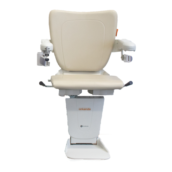
CONTENT Thank you for choosing a Handicare stairlift. This manual is for the Handicare1100 lift with a manual seat or powered seat type. The lift is for indoor use only. The manual includes instructions for the standard and the optional features. - Seite 4 TOOLS & PARTS USED TOOLS TECHNICAL MANUAL HAND TIGHT Not loose, but not really tight either. Somewhere around 1 or 2 Nm. AA21859 7-9 mm 10 mm 8 mm 44-221Lb-In 5-25Nm min. 30 mm 3 mm Torx T20 4 mm 5 mm Ph 2 Ph 3...
- Seite 5 Only a technician certified for this lift should install this lift (for more detailled information about the required competence see attachment H of this manual). General required knowledge can be found in the 1100 Technical Manual. The latest instructions for the lift and instructions for options are available for download at www.handicarepartners.com.
- Seite 6 Handicare Stairlifts B.V. Handicare Stairlifts B.V. Newtonstraat 35, 1704SB Heerhugowaard Newtonstraat 35, 1704SB Heerhugowaard The Netherlands The Netherlands T: +31 72 576 8888, www.handicare.com T: +31 72 576 8888, www.handicare.com DRIVE: FRICTION DRIVE DRIVE: FRICTION DRIVE RATED LOAD: RATED LOAD:...
- Seite 7 EXPLANATION [1.2]Check that all the parts are present. The part numbers shown next to the parts are given in the installation manual at the time of installation. When replacing parts on an existing stairlift, always use parts with identical part numbers. Hand tight = not loose, but not really tight either.
-
Seite 8: Rail
RAIL OPTION AA17805 INSTALL EASY HINGE OPTION Angle φ min. max. AA17806 CA/US INSTALL SLIDE TRACK SlideTrack Use the speci c manuals, supplied with the options 3 railparts 3 railparts L>4450mm L>4370mm [175 inch] [172 inch] 2 railparts 2 railparts L<3170mm L<3090mm [125 inch]... - Seite 9 EXPLANATION [2.1]If present install now the hinged rail or the slide track. [2.2]Measure the distance between the upper floor and the ground floor (diagonally). This is the length L. [2.3]Check what configuration you are going to install: Flush footrest landing or Footrest landing above floor. The length L must be at least 3170 mm ( ) for a configuration: flush footrest landing, or at least 3090 mm ( 125 inch...
- Seite 10 RAIL CLEAN 10mm INSTALLATION MANUAL...
- Seite 11 EXPLANATION [2.5]Deburr the sharp edges on the sawn end {A}. Remove as much debris as possible from the rail {B}. Remove the wrap from the rail{C}. [2.6]Position the joint (half of the lenght in the rail). [2.7]Unscrew the nut on the joint until the joint is secure. Make sure the joint is parallel to the rail. [2.8]Place the protective mat at the bottom of the stairs {A} and rest the sawn lower rail part, with the sawn end at the bottom, on the stairs and the mat {B}.
- Seite 12 RAIL JOINT 2.10 8 Nm 71 Lb-In 4 mm LAST FIRST STEP AFTER JOINT LAST STEP FOR JOINT FIRST 2.12 2.11 INSTALLATION MANUAL...
- Seite 13 EXPLANATION [2.9] Fit the other rail part tight up against the lower rail part, using the joint{A}. Check the rail for colour difference. The marks inside the profile can be helpfull by this. If necessary, turn the upper rail part upside down{B}. [2.10]Position both aluminium parts of the rail joint to the rail {A}.
- Seite 14 RAIL WIRING 0 Nm 221 Lb-In 4x[2x] 5 mm 25 Nm 5 mm 4x[2x] 2.13 2.14 2.16 2.15 INSTALLATION MANUAL...
- Seite 15 EXPLANATION [2.13]Adjust the rail so that it sits on the stair noses{A}. Press the brackets against the steps {B}. Secure the brackets in position by tightening the bolts (hand tight){C} . [2.14]Finally tighten the bolts securely (25 Nm/221 Lb-In). [2.15]Place the entire rail one step higher. [2.16]Check that the correct charger has been supplied.
- Seite 16 RAIL LOADING STRIP 2.18 2.17 2.20 2.19 INSTALLATION MANUAL...
- Seite 17 EXPLANATION [2.17]Fit the connectors to the strip. [2.18]Connect both of the resulting ends to the charging strip (polarity is not important) {A}, by squeezing the connectors {A}. [2.19]Choose the best location for the charger, either at the top or bottom of the stairs {A}. Starting from this location, align the charging strip along the side of the profile, in the groove (wall side) in the rail{B}.
- Seite 18 RAIL END STOP 71 Lb-In CHARGER UPSTAIRS: 8 Nm INSTALL ENDSTOP{A} LATER 4 mm 0 Nm 3 mm 2.21 2.22 CHARGER UPSTAIRS: FIT CAP{B} LATER 2.23 2.15 2.24 INSTALLATION MANUAL...
- Seite 19 EXPLANATION [2.21]Secure the end stop to the rail (aligned precisely with the rail end) {A}. Screw the earth wire into the rail {B}. Tighten the bolts securely {C}{8 Nm/71 lb-in}. [2.22]Slide the limit actuator into the rail, up against the end stop (slanting sides at the top!) {A}. Fit the circlip over the limit actuator{B}.
- Seite 20 RAIL FIXATION STRINGER 6.3x45(4x) 170 mm 6.7 inch 4x[1x] 160 mm 6.3 inch OBSTACLE 2.26 OPTION INSTALL ZERO INTRUSION AA23000 Use the speci c manual, supplied with this option 2.25 2.27 SERVICING min. 50 lux cable length maximum 6 ft UK ONLY Note: all mains wiring/electrical connection must comply with the standards in force at...
- Seite 21 EXPLANATION [2.25]Replace the entire rail one step lower and achieve a minimum 45 mm ( ) clearance between the rail and 1.77 inch the stairs{A}. Next, position the rail in relation to the wall/stringer/obstacle{B}. The minimum allowable clearance from the wall or obstacle is ).
-
Seite 22: Powerpack
POWER PACK PLACING 4 mm 7-9 mm 4 mm INSTALLATION MANUAL... - Seite 23 EXPLANATION [3.1]Remove the power pack from the box and put it on the floor at the top of the stairs. Install temporarily the endstop just below the bracket. [3.2]Place the power pack on the rail (the batteries on the front of the power pack). Ensure that the motorised roll- ers engage properly with the rail and looms do not pinch between the rail and the unit.
- Seite 24 POWER PACK CONNECTING INSTALLATION MANUAL...
- Seite 25 EXPLANATION [3.5]Connect the cable between the two batteries to the positive terminal on the battery. [3.6]The power pack is now energised. A “0” symbol means that everything is fine and the unit is charging. A “2” and bleeping means that the unit is not properly connected: 1.
-
Seite 26: 4- Finish Rail
FINISH RAIL ENDSTOP 8 Nm 71 Lb-In 4 mm 0 Nm 3 mm CHARGER UPSTAIRS 4.3A INSTALLATION MANUAL... - Seite 27 EXPLANATION [4.1]Secure the end stop to the rail (aligned precisely with the rail end) {A}. Tighten the bolts securely {C} {8 Nm/71 lb-in}. [4.2]Slide the limit actuator into the rail, up against the end stop (slanting sides at the top!) {A}. Fit the circlip over the limit actuator{B}.
-
Seite 28: 5-Chassis
CHASSIS ADAPTOR PLATE RIGHT CONFIGURATION NEXT LH man LH man RH man PAGE RH man LH pow LH pow RH pow RH pow ONE INSTALL ONLY M6x12 M6x12 M6x40 M6x12 M6x12 M6x12 LEFT CONFIGURATION LEFT CONFIGURATION M6x40 0 Nm 5 mm 5 mm M6x12 5.3L... - Seite 29 EXPLANATION [5.1]Remove the tilt chassis components from the box. LEFT CONFIGURATION: [5.2_L]Assemble the adaptor set (adaptor plates/bolts/washers/bracket). [5.3_L]Secure the adaptor plates, washers and bracket to the bottom of the power pack (hand tight){B}. Adjust the adaptor plate until it is horizontal {A}. [5.4_L]Screw the two chassis bolts half way (2 turns) into the adaptor plate.
- Seite 30 CHASSIS POWER PACK RIGHT CONFIGURATION M6x40 0 Nm 5 mm 5 mm M6x12 5.4R 5.3R 5.2R 5 mm M6x12 14Nm 124 Lb-In M6x40 INSTALLATION MANUAL...
- Seite 31 EXPLANATION RIGHT CONFIGURATION: [5.2_R]Assemble the adaptor set (adaptor plates/bolts/washers/bracket). [5.3_R]Secure the adaptor plates, washers and bracket to the bottom of the power pack (hand tight){B}. Adjust the adaptor plate until it is horizontal {A}. [5.4_R]Screw the two chassis bolts half way (2 turns) into the adaptor plate. [5.5]Tighten the bolt securely (14 Nm/124 Lb-In).
- Seite 32 CHASSIS FASTEN 0 Nm 5 mm 14 Nm 124 Lb-In 5 mm 5.10 INSTALLATION MANUAL...
- Seite 33 EXPLANATION [5.9]Use a spirit level to level the lift{A} and fasten the six bolts hand tight{B}. [5.10]Finally tighten the six bolts securely (14 Nm/124 Lb-In). [5.9]Gebruik een waterpas om de lift verticaal te zetten{A} en draai de zes bouten handvast{B}. [5.10]Draai vervolgens de zes bouten stevig vast (14 Nm).
- Seite 34 CHASSIS SEAT LOOM 5.12 Ph 3 5.11 USA ONLY {page 100} CHILD USA ONLY {page 110} CHILD CLICK! 5.14 5.13 INSTALLATION MANUAL...
- Seite 35 EXPLANATION [5.11]Drill two self drilling screws through the designated holes into the second adaptor plate. [5.12]Disconnect the shortcut connector from the PCB. [5.13]Run the main loom through the chassis and adaptor plate. [5.14]Connect the main loom {A1} to the PCB. [5.11]Boor twee zelfborende schroeven door de daarvoor bestemde gaten in de tweede adapterplaat.
- Seite 36 CHASSIS SEAT LOOM 5.16 5.15 0 Nm 10mm 5.17 5.18 INSTALLATION MANUAL...
- Seite 37 EXPLANATION [5.15]Remove the power pack covers from the box. Remove from one side (on the accessible side of the stairlift) the cut-out{A}. Deburr the sharp edges {B}. [5.16]Tilt the power pack cover onto the unit. Be careful not to trap the main loom. [5.17]Carefully push the power pack cover into the four brackets on the unit.
- Seite 38 CHASSIS COVERS 0 Nm 3 mm INSIDE VIEW 5.20 5.19 CLICK! CLICK! 3 mm 5.22 5.21 INSTALLATION MANUAL...
- Seite 39 EXPLANATION [5.19]Check the activation rods{A}. Slide the safety guard over the rail onto the power pack {B} and insert the bolts provided {C}. [5.20]Secure the guard firmly in place. [5.21]Fit the second safety guard {A} and secure this firmly in place too {B}. Test the function of the activation rods{C}. [5.22]Fit the diagnostics display cover.
- Seite 40 CHASSIS SEAT STEM ADAPTOR RIGHT CONFIGURATION 5.24 5.23 LEFT CONFIGURATION 520mm 490 mm 460 mm 430 mm inch 20.47 19.29 18.11 16.93 5.25 INSTALLATION MANUAL...
- Seite 41 EXPLANATION [5.23]Slide the clamp plate into the groove in the tilt chassis. [5.24]Screw the four bolts into the clamp plate. Leave the bolt heads 4mm ( ) clear of the frame. 0.18 inch [5.25]Determine the required seat height: the height is adjustable from 430 mm upto 520 mm ( 16.93 inch upto ) {A}.
- Seite 42 CHASSIS STEM 14Nm 124 Lb-In 5 mm GO TO PAGE 48 Right Left POWERED SWIVEL Right Left MANUAL SWIVEL 5.26 5.27 INSTALLATION MANUAL...
- Seite 43 EXPLANATION [5.26]Ensure that the seat support is as far down as it will go{A}. Tighten the four bolts securely{B} (14Nm/124 Lb-In). [5.27]Remove the seat from the box. If you are installing an powered seat (with the powered options), continue this manual on page 48.
-
Seite 44: 6- Seat (Manual)
MANUAL SEAT LOCKING MANUAL 10 mm 10 mm INSTALLATION MANUAL... - Seite 45 EXPLANATION [6.1]Remove the securing bolt from the bottom of the seat. [6.2]Carefully lower the seat onto the seat support tube, keeping the seat parallel to the tilt chassis, until the profiled cam under the seat comes into contact with the switch. [6.3]Refit the securing bolt and tighten firmly.
- Seite 46 MANUAL SEAT GUIDING LOOMS SEAT LOOM SWIVEL S LOOM IN THE COLOURED SCHEME ON THE BACKCOVER YOU CAN FIND THE MARKED CONNECTIONS. INSTALLATION MANUAL...
- Seite 47 EXPLANATION [6.5]Refit the cover {A} and tighten the screws {B}. Be carefull with the wiring. [6.6]Run the seat loom in front of the seat support and through the tilt chassis. [6.7]Fasten the looms with a tiewrap. [6.8]Connect the seat cable to the PCB cable {A8}{A}.Connect the seat cable to the swivel cable {A9}{B}. [6.5]Plaats de kap terug{A} en schroef deze vast{B}.
- Seite 48 MANUAL SEAT CONNECTING LOOMS =left =right BLUE 6.10 6.12 GO TO PAGE 56 6.11 INSTALLATION MANUAL...
- Seite 49 EXPLANATION [6.9]Connect the earth wires to the chassis. [6.10]The left-hand configuration is connected as standard for the footplate cable. If the stairlift needs the right-hand configuration, the connector with the blue wires should be connected {A14+A15}. On the electrical diagram on the backcover the marked connections are explained further.
-
Seite 50: 7- Seat (Powered)
POWERED SEAT LOCKING POWERED 10 mm 10 mm INSTALLATION MANUAL... - Seite 51 EXPLANATION [7.1]Remove the securing bolt from the bottom of the seat. [7.2]Carefully lower the seat onto the seat support tube, keeping the seat parallel to the tilt chassis, until the profiled cam under the seat comes into contact with the switch. [7.3]Refit the securing bolt and tighten firmly.
- Seite 52 POWERED SEAT STEM COVER RELEASE LOOM SEAT LOOM SWIVEL S LOOM INSTALLATION MANUAL...
- Seite 53 EXPLANATION [7.5]Run the swivel release cable through the seat support tube. [7.6]Refit the cover {A} and tighten the screws {B}. Be carefull with the wiring. [7.6]Run the seat looms in front of the seat support and through the tilt chassis. [7.8]Fasten the looms with a tiewrap.
- Seite 54 POWERED SEAT POWERED OPTION PCB LEFT BLACK BLACK WHITE BLACK 7.9L 7.10L RIGHT BLACK WHITE BLACK BLACK 7.10R 7.9R INSTALLATION MANUAL...
- Seite 55 EXPLANATION Connect the looms for the correct configuration (left=L and right=R): [7.9]Connect the power loom on the powered option PCB(A16). Be carefull with touching the print when connecting wires on the PCB. [7.10]Connect the swivel motor loom with the PCB (A18){A}. Connect the swivel release loom with the swivel motor loom(A19){B}.
- Seite 56 POWERED SEAT CONNECTING LOOMS IN THE COLOURED SCHEME ON THE BACKCOVER YOU CAN FIND THE MARKED CONNECTIONS. =left =right BLUE 7.12 7.13 7.11 7.15 7.14 INSTALLATION MANUAL...
- Seite 57 EXPLANATION [7.11]Connect the seat cable to the PCB cable {A8}. Connect the seat cable to the swivel cable {A9}. [7.12]Connect the earth wires to the chassis. [7.13]The left-hand configuration is connected as standard for the footplate cable. If the stairlift needs the right-hand configuration, the connector with the blue wires should be connected {A14+A15}.
-
Seite 58: 8- Finish
FINISH COVERS ONLY POWERED SWIVEL ! LEFT OR RIGHT INSTALLATION MANUAL... - Seite 59 EXPLANATION [8.1]Fit the bottom tilt chassis cover {A}. Slide hereby the two ribs of the cover into the recesses of the frame {B}. Secure the cover using two screws {B}. [8.2]Cut out the appropriate groove in the upper tilt chassis cover. [8.3]In case of installation of the powered swivel, cut out the appropriate groove in the upper tilt chassis cover.
- Seite 60 FINISH COVERS 3 mm 0 mm 8 mm INSTALLATION MANUAL...
- Seite 61 EXPLANATION [8.4] Fit threaded pins in the upper tilt chassis cover{A}. Fit the upper tilt chassis cover; the two plastic pins of the cover in the small holes of the seat support {B}. [8.5]Fasten the cover. [8.6]Position the rear tilt chassis cover {A} and fasten the screws {B}. [8.4]Monteer de schroefdraadpinnen in de bovenste tilt chassis kap{A}.
- Seite 62 FINISH TRACK 6,3 x 50 (4x4) AA20942 Ph 3 6.3x45(3x) 6.3x45(3x) 8.10 8.11 INSTALLATION MANUAL...
- Seite 63 EXPLANATION [8.7+8.8]Ride the lift up en down. Check the positon of the lift. [8.9]Secure the bracket in position using screws (for wooden stairs) or rawl plugs/screws (for concrete/stone stairs). [8.10]Secure the bracket in position using screws (for wooden stairs) or rawl plugs/screws (for concrete/stone stairs). [8.11]Secure the brackets in position using screws (for wooden stairs) or rawl plugs/screws (for concrete/stone stairs).
-
Seite 64: Remote Controls
REMOTE CONTROLS INSTALLATION 2x[2x] INSTALLATION MANUAL... - Seite 65 EXPLANATION [9.1]Mount the wall plate of the remote control with two screws on a solid background. Mount a remote control at the top and bottom of the stairs. [9.2]Insert the batteries into the remote control. [9.3]Mount the remote control into the holster{A} and fix it with a screw{B}. [9.4]Click the holster/remote control over the wall plate.
- Seite 66 REMOTE CONTROLS LINKING INSTALL RF REMOTE CONTROL KIT (AAxxxx ) 30 sec INSTALLATION MANUAL...
- Seite 67 EXPLANATION [9.5]The remote controls supplied with the lift should work out of the box (the seat need to be installed !). If the lift does not travel up or down the stairs when the corresponding remote control buttons are pressed, follow the pro- cedure set out next.
- Seite 68 REMOTE CONTROLS CHANGING CHANNELS <50 m < 164 ft RED: IR 9.10 LIFT 1(default) LIFT 2 LIFT 3 LIFT 4 CLICK! Link the remote controls: SEE g. 9.6-9.8 ON PAGE 64 9.11 9.12 INSTALLATION MANUAL...
- Seite 69 EXPLANATION [9.9] For multiple lift applications: possibly the remote controls need be to reset. [9.10]Remove the caps on the backside of the remote controls. The cap of the infrared remote control is red and the cap of the radiofrequecy controlled remote control is green/orange. [9.11]Set the dip switches on both remote controls of the same lift to the same settings.
-
Seite 70: Check
CHECK MEASUREMENTS 25 - 45 : 154 kg 45 - 50 : 143 kg 143 kg 315 lbs 10.1 10.2 10.3 3.94 inch 10.5 10.4 INSTALLATION MANUAL... - Seite 71 EXPLANATION [10.1]Place a weight of 143 kg ( ) on the chair and ride the chair up and down. Check that everything 315 lbs is working satisfactorily. Do this only to test the stairlift and make sure no-one is sitting on the seat. [10.2]Move the joystick up and down.
- Seite 72 CHECK SWIVEL-SAFETY BELT SEE QUICK REFERENCE GUIDE 10.7 CLICK! 10.6 10.8 {page 96} 10.9 10.10 INSTALLATION MANUAL...
- Seite 73 EXPLANATION [10.6]Check the position of the bulkhead: check that there is no obstacle within 1000 mm above the seat in the direction of movement of the lift. [10.7]Check the diagnostic display; make sure there are no fault messages. See the user manual for the error codes. [10.8]Check the seat belt.
- Seite 74 CHECK SAFETY LIMITS 10.11 10.12 10.13 6.8lbs 6.8lbs 10.14 INSTALLATION MANUAL...
- Seite 75 EXPLANATION [10.11]Check the powered swivel function. [10.12]Check the powered footrest function. [10.13]Ensure that the diagnostic display shows a “-” symbol at all points along the rail. [10.14]Check the safety stops. [10.11]Check de automatische draaifunctie. [10.12]Check de automatische voetenplank. [10.13]Verzeker je dat de diagnostic display een “-” aangeeft op elke positie op de rail. [10.14]Check de veiligheidsblokkeringen.
- Seite 76 CHECK ARMRESTS 10.15 10.16 7.15 10.17 INSTALLATION MANUAL...
- Seite 77 EXPLANATION [10.15]Fold the armrest up. The stairlift must stop immediately. Put the armrest back down and check that the stairlift operates normally again. [10.16]Release the joystick toggle switch. The stairlift should stop within 2 cm ( 0.8 inch [10.17]Press the stop button. The lift must stop immediately. Press the stop button again; check that the stairlift operates normally.
- Seite 78 CHECK KEYSWITCH - STOPS 10.18 10.19 CLICK! CLICK! 10.20 10.21 INSTALLATION MANUAL...
- Seite 79 EXPLANATION [10.18]Turn the key to the OFF position and ensure that the stairlift will not move. The diagnostic display should show a “O”. Turn the key to the ON position. The stairlift should be able to move again. [10.19]While moving the stairlift, swivel the seat; the stairlift must stop immediately. [10.20]Check the manual swivel function and that the end stops work satisfactorily (it clicks at the end).
- Seite 80 IDEAS IDEAS REMARKS Fax (+31(0)72 5768877) or mail (data@handicare.com) IDEAS a filled in and signed form to Handicare. Fax (+31(0)72 5768877) or mail (data@handicare.com) USER MANUAL a filled in and signed form to Handicare. 10.22 Fax (+31(0)72 5768877) or mail (data@handicare.com) 10.24...
- Seite 81 été signée par l’utilisateur. Ces documents doivent être conservés par l’entreprise installant le matériel et être consultables par Handicare à la demande. [10.25]Prenez dans le manuel l’étiquette d’avertissement appropriée, puis apposez sur l’étiquette les autocollants corrects de l’année et du poids {A}.
- Seite 82 Model: 1100 ST Handicare Stairlifts B.V. CHECK Newtonstraat 35, 1704SB Heerhugowaard The Netherlands T: +31 72 576 8888, www.handicare.com DRIVE: FRICTION DRIVE PLACING LABELS RATED LOAD: 264 lbs/120 kg (37 RATED SPEED: 21.7 �/min (0.11m/s) CONFORMS TO ASME A18.1 & ASME A17.5 CERTIFIED TO CSA B44.1 &...
- Seite 83 EXPLANATION [10.28]Fill in the details on the small label{A}. Mount the small label on the detection cover{B}. Mount the large label on the detection cover{C}. INSTALLATION MANUAL...
-
Seite 84: Attachments
ATTACHMENTS BIJLAGE ANEXO ANHANG ANNEXE APPENDICE INSTALLATION MANUAL... - Seite 85 RAIL CUTTING (mm) [1]Measure the distance between the landingfloor and [1]Meet als eerste de afstand tussen de verdiepings- the ground floor (diagonal) = L vloer en de begane grond (diagonaal) = L [2]Verify the related cut-out dimension C in the table [2]Lees de samenhangende zaagmaat C uit de tabel [3]Saw the rail part: 4700 mm - L - C [3]Zaag het raildeel op 4700 mm - L - C...
- Seite 86 RAIL CUTTING (inch) [1]At First measure the distance between the landingfloor and the ground floor (diagonal) = L [2]Verify the related cut-out dimension C in the table [3]Saw the rail part: 185 inch - L - C Flush footrest landing Footrest landing above floor inch Ф...
- Seite 87 3 RAILPARTS L >4450 mm (L >4370 mm{footrest landing above floor}): 3 railparts will be needed. L >4450 mm (L >4370 mm{footrest landing above floor}): 3 raildelen zijn nodig. L >4450 mm (L >4370 mm{footrest landing above floor}), se necesitarán 3 piezas del riel. L >4450 mm (L >4370 mm{footrest landing above floor}): es werden 3 Schienenteile benötigt.
- Seite 88 RAIL CUTTING ON BOTH ENDS(mm) Saw the rail parts of equal length. Zaag de raildelen even lang. Be sure of the correct orientation of the rail parts because Zorg voor een juiste oriëntatie van de raildelen i.v.m. of possible color difference. kleurverschil.
- Seite 89 RAIL CUTTING ON BOTH ENDS(inch) Saw the rail parts of equal length. Be sure of the correct orientation of the rail parts because of possible No lift shall be installed to color difference. operate on a greater incline than 45 deg as measured on the mean.
- Seite 90 EMERGENCY OPERATION>TRACK STOP B.1 C.1 INSTALLATION MANUAL...
- Seite 91 EXPLANATION [D.1]When the stairlift stops unexpectedly and no longer moves any further, the emergency loom can be used to move the lift to a stopping point. [D.2]Take away the display cap and unscrew the unit covers. [D.3]Remove the covers from the unit. [D.4]Disconnect the motor wires one by one{A} and put them, on the corresponding position, on the emergency loom{B}.
- Seite 92 EMERGENCY OPERATION>TRACK INSTALLATION MANUAL...
- Seite 93 EXPLANATION [D.5]Connect the emergency loom to an extended batterie. [D.6]Use the buttons to ride lift to a stopping point. [D.7]Connect the motor wires one by one{A} and put them, on the corresponding position, on the PCB{B}. [D.8]Refit the covers{A}. Fasten the unit covers and refit the display cap{B}. [D.5]Verbind de noodkabel met de losse externe accu.
- Seite 94 ARMRESTS CONVERSION 4 mm Ph 3 8 mm LEFT 17 mm 17 mm RIGHT 8 mm INSTALLATION MANUAL...
- Seite 95 EXPLANATION [E.1]Unscrew the back cover{A} and remove the back cover{B}. [E.2]Unscrew the upholstery{A} and remove the upholstery{B}. [E.3]Remove the tiewraps. [E.4]Remove the armrests. [E.1]Schroef de achterkap los{A} en verwijder deze{B}. [E.2]Schroef de stoelbekleding los{A} en verwijder deze{B}. [E.3]Verwijder de tiewraps. [E.4]Verwijder de armleuningen.
- Seite 96 ARMRESTS CONVERSION 8 mm 21 Nm LEFT LEFT RIGHT RIGHT INSTALLATION MANUAL...
- Seite 97 EXPLANATION [E.5]Reinstall the armrests on the other sides of the seat. [E.6]Fasten the armrests (21 Nm). Use new nyloc nuts, supplied in the fitting kit. [E.7]Fold up the armrests{A}. Fasten the armrest cables with tiewraps{B}. Be sure the cables are not too tight. [E.8]Shorten the tiewraps.
- Seite 98 ARMRESTS CONVERSION 4 mm 5 Nm E.10 Ph 3 E.11 E.12 INSTALLATION MANUAL...
- Seite 99 EXPLANATION [E.9]Fasten the armrest cable to the seat frame with a tiewrap. [E.10]Reinstall the upholstery. [E.11]Put any excess wiring into the back cover cavity {A}.Position the back cover{B}. Do not squeeze the wiring. [E.12]Fasten the back cover. [E.9]Maak de stoelkabel met een tiewrap vast aan het stoelframe. [E.10]Herinstalleer de bekleding.
-
Seite 100: Footrest Adjustment
FOOTREST ADJUSTMENT 5 mm INSTALLATION MANUAL... - Seite 101 EXPLANATION [F.1]Fold up the footplate. [F.2]Remove the cap (2x). [F.3]Loosen the adjustment bolts (2x). [F.4]Refit the cap (2x). [F.5]Fold down the footplate and check the new position of the footplate. [F.1]Klap de voetenplank op. [F.2]Verwijder het kapje(2x). [F.3]Draai de stelbouten (2x) los. [F.4]Plaats het kapje terug(2x).
- Seite 102 FINAL LIMIT SWITCH USED TOOLS 2,5 mm 3 mm 44-221Lb-In 5-25Nm INSTALLATION MANUAL...
- Seite 103 EXPLANATION [G.1]Run the main loom through the chassis and adaptor plate. [G.1]Rijg de hoofdkabelboom door het chassis en de adaptorplaat. [G.1]Pase el mazo de cables principal por el chasis y la placa adaptadora. [G.1]Führen Sie den Hauptkabelbaum durch das Fahrgestell und die Adapterplatte. [G.1]Faites passer le faisceau de câbles principal à...
- Seite 104 FINAL LIMIT SWITCH RIGHT-HAND CONFIGURATION 0 Nm 2,5 mm LEFT-HAND CONFIGURATION 0 Nm 2,5 mm INSTALLATION MANUAL...
- Seite 105 EXPLANATION [G.2]For a right-hand configuration assemble the clip and switch in the manner indicated. Screw the assembly in place with the supplied bolts. For proper operation of the switch, the switch must be positioned on the clip in this manner. [G.3]For a left-hand configuration assemble the clip and switch in the manner indicated.
- Seite 106 FINAL LIMIT SWITCH CLICK! CONTINUE INSTALLATION GO TO FIGUUR 5.15 OF THIS MANUAL AFTER INSTALLATION: TEST THE SWITCH 3 mm INSTALLATION MANUAL...
- Seite 107 EXPLANATION [G.4]Position the final limit switch on the topside of the power pack{A}. Make sure it is a good fit {B}. [G.5]Run the final limit switch cable through the chassis. [G.6]Connect the final limit switch cable to the main loom{A}. Connect the main loom(A1) to the PCB{B}. Now continue with the normal installation from Figure 5.15 in this manual.
- Seite 108 FINAL LIMIT SWITCH RELEASE THE FINAL LIMIT 4 mm INSTALLATION MANUAL...
- Seite 109 EXPLANATION [G.8]Drive the lift up the stairs. The lift is stopped on the final limit switch if the display shows a “ ” and the lift can no longer move in either direction. [G.9]The limit switch can be released by removing the end stop. Next, drive the lift down. [G.8]Rijd de lift naar boven.
- Seite 110 FINAL LIMIT SWITCH 8 Nm 71 Lb-In REBUILT THE LIFT 4 mm 0 Nm 3 mm G.10 G.11 G.12 INSTALLATION MANUAL...
- Seite 111 EXPLANATION Rebuilt the lift: [G.10]Secure the end stop to the rail (aligned precisely with the rail end){A}. Tighten the bolts securely{C}{8 Nm/71 lb-in}. [G.11]Slide the limit actuator into the rail, up against the end stop (slanting sides at the top!) {A}. Fit the circlip over the limit actuator{B}.
- Seite 112 LOCKABLE SWITCH USED TOOLS KIT: Pz 1 INSTALLATION MANUAL...
- Seite 113 EXPLANATION [1]Remove the diagnostics display cover. [2]Unscrew the safety guards{A}. Slide the safety guard over the rail and remove from the power pack{B}. [3]Remove the two nyloc nuts. [4]Remove power pack cover from the unit. [1]Verwijder de kap van de diagnostische display. [2]Draai de boutjes los van de veiligheidskappen{A}.
- Seite 114 LOCKABLE SWITCH INSTALLATION MANUAL...
- Seite 115 EXPLANATION [5]Disconnect the +wire of the battery. [6]Connect the holiday switch with the battery{A}. Connect the holiday switch with the “old” + wire{B}. [7]Tilt the power pack cover onto the unit. Be careful not to trap the seat cable{A}. Carefully push the slot on the power pack cover into the four brackets on the unit{B}.
- Seite 116 LOCKABLE SWITCH CLICK! CLICK! INSTALLATION MANUAL...
- Seite 117 EXPLANATION [11]Click the holiday switch into the hole. [12]Switch on the holiday switch{A}. Install the locking pin{B}. [13]Replace the diagnostics display cover. [14]check if the lift are still good functioning. [15]Check if the detection covers is still good functioning. [11]Klik de schakelaar in het gat. [12]Zet de schakelaar aan{A}.
-
Seite 118: Very Important
The stairlift engineer must read the manual to understand all the information to enable safe installation and/or commissioning of the stairlift. In the absence of any negligence or breach of duty on the part of Handicare Accessibility Limited, no liability or responsibility will be accepted by it for any loss or damage arising from anyone’s failure to follow and adhere to the guidance in the manual in connection with the installing... -
Seite 119: Zeer Belangrijk
Indien Handicare Accessibility Limited niet nalatig is geweest en de wettelijke plicht niet heeft verzuimd, zal het bedrijf geen aansprakelijkheid of verantwoordelijkheid aanvaarden voor eventueel verlies of schade dat/die is ontstaan doordat iemand de instructies in de handleiding met betrekking tot de installatie en/of ingebruikname van de traplift niet heeft opgevolgd of er niet aan voldoet. -
Seite 120: Très Important
Salvo casi di negligenza o contravvenzione a un obbligo da parte di Handicare Accessibility Limited, quest’ultima non si assumerà alcuna responsabilità per perdite o danni derivanti dall’altrui mancata osservanza delle indicazioni riportate nel manuale in relazione all’installazione e/o alla riparazione del montascale. - Seite 122 Concord, ON L4K 4Z9 Canada Deutschland T : 905.850.9003 Tel: +49 (0) 571 973398-55 Fax: +49 (0) 571 973398-56 F : 416.260.0256 data@handicare.com Handicare Montascale Italia Via Chiaviche 17 46020 Pegognaga (MN) Italy Tel: +39 (0) 376 143 3516 handicare-montascale.it INSTALLATION MANUAL INSTALLATIEHANDLEIDING...