Ducati Performance 96680833A Montageanleitung
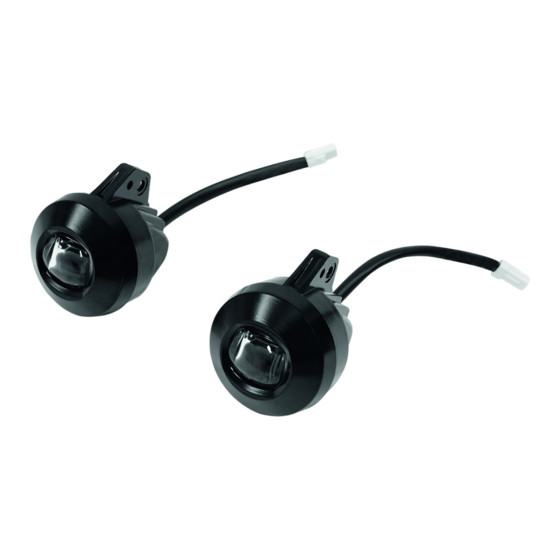
Kit led-zusatzscheinwerfer
Inhaltsverzeichnis
Quicklinks
ISTR - 974 / 00
Kit faretti a led supplementari
Additional LED spotlight kit
Simbologia
Per una lettura rapida e razionale sono stati impiegati simboli che
evidenziano situazioni di massima attenzione, consigli pratici o
semplici informazioni. Prestare molta attenzione al significato dei
simboli, in quanto la loro funzione è quella di non dovere ripete-
re concetti tecnici o avvertenze di sicurezza. Sono da considerare,
quindi, dei veri e propri "promemoria". Consultare questa pagina
ogni volta che sorgeranno dubbi sul loro significato.
Attenzione
La non osservanza delle istruzioni riportate può creare una situa-
zione di pericolo e causare gravi lesioni personali e anche la morte.
Importante
Indica la possibilità di arrecare danno al veicolo e/o ai suoi compo-
nenti se le istruzioni riportate non vengono eseguite.
Note
Fornisce utili informazioni sull'operazione in corso.
Riferimenti
I particolari evidenziati in grigio e riferimento numerico (Es.
rappresentano l'accessorio da installare e gli eventuali componenti
di montaggio forniti a kit.
I particolari con riferimento alfabetico (Es.
componenti originali presenti sul motoveicolo.
Tutte le indicazioni destro o sinistro si riferiscono al senso di marcia
del motociclo.
Avvertenze generali
Attenzione
Le operazioni riportate nelle pagine seguenti devono essere ese-
guite da un tecnico specializzato o da un'officina autorizzata Du-
cati.
Attenzione
Le operazioni riportate nelle pagine seguenti se non eseguite a re-
gola d'arte possono pregiudicare la sicurezza del pilota.
Note
Documentazione necessaria per eseguire il montaggio del Kit è il
Manuale Officina, relativo al modello di moto in vostro possesso.
Note
Nel caso fosse necessaria la sostituzione di un componente del kit
consultare la tavola ricambi allegata.
1
- 96680833A
- 96680833A
1
)
A
) rappresentano i
Symbols
The symbols used in this manual are aimed at making reading di-
rect and easy. The symbols are used either to draw the reader's
attention on potentially hazardous conditions, or to give practical
advice or to supply general information. Pay the utmost attention
to these symbols as they are used to remind of technical principles
or safety measures which will not be repeated extensively. They
must therefore be considered as "reminders". Check with this page
in case of doubt about their meaning.
Warning
Failure to comply with these instructions may put you at risk and
lead to severe injury or death.
Important
It indicates the possibility of damaging the motorcycle and/or its
components if the instructions are not followed.
Notes
It supplies useful information about the operation in progress.
References
The parts highlighted in grey and with a reference number (e.g.
) represent the accessory to be installed and any assembly compo-
nents supplied with the kit.
The parts with alphabetic reference (e.g.
components present on the motorcycle.
All left and right indications are referred to the motorcycle direc-
tion of travel (forward riding position).
General notes
Warning
The operations listed in the following pages must be carried out by
a specialised technician or by a Ducati authorised service centre.
Warning
Carefully perform the operations on the following pages since they
might negatively affect rider safety.
Notes
The Workshop Manual of your motorcycle model is the documen-
tation required to assemble the Kit.
Notes
Should it be necessary to change any kit parts, please refer to the
attached spare part table.
Warning
Operating, servicing and maintaining a passenger vehicle or off-
highway motor vehicle can expose you to chemicals including en-
gine exhaust, carbon monoxide, phthalates, and lead, which are
known to the State of California to cause cancer and birth defects
or other reproductive harm. To minimize exposure, avoid breath-
ing exhaust, do not idle the engine except as necessary, service
your vehicle in a well-ventilated area and wear gloves or wash your
hands frequently when servicing your vehicle. For more informa-
tion go to www.P65Warnings.ca.gov/passenger-vehicle.
1
A
) represent the original
Inhaltsverzeichnis

Verwandte Anleitungen für Ducati Performance 96680833A


Inhaltszusammenfassung für Ducati Performance 96680833A
- Seite 1 Du- The operations listed in the following pages must be carried out by cati. a specialised technician or by a Ducati authorised service centre. Attenzione Warning Le operazioni riportate nelle pagine seguenti se non eseguite a re- Carefully perform the operations on the following pages since they gola d’arte possono pregiudicare la sicurezza del pilota.
- Seite 2 ISTR 974 / 00 Importante Important I componenti del kit possono essere soggetti ad aggiornamenti; The parts of the kit can be updated; for information always up to consultare il DCS (Dealer Communication System) per avere infor- date, please refer to DCS (Dealer Communication System). mazioni sempre aggiornate.
-
Seite 3: Side Panel Disassembly
ISTR 974 / 00 Smontaggio componenti originali (versione Removing original components (Multistrada Multistrada 950 / Multistrada 1260) 950 / Multistrada 1260 version) Smontaggio ali laterali Side panel disassembly Svitare le n.2 viti (A1) e rimuovere l’ala destra (A). Procedere in ma- Loosen no.2 screws (A1) and remove RH cowling (A). - Seite 4 ISTR 974 / 00 Operando sul lato sinistro del motoveicolo, rimuovere il tappo (W1) Working on the LH side of the motorcycle, remove plug (W1) from dalla presa (W2) del cablaggio principale di alimentazione. socket (W2) of the main power supply wiring.
-
Seite 5: Removing The Seat
ISTR 974 / 00 Smontaggio componenti originali Removing original components (Versioni Multistrada Enduro) (Multistrada Enduro versions) Smontaggio sella Removing the seat Inserire la chiave (S) nella serratura sella e ruotarla in senso ora- Insert the key (S) into the seat lock and turn it clockwise until the rio fino a sentire lo scatto del gancio, come indicato in figura (Y1). - Seite 6 ISTR 974 / 00 Smontaggio convogliatori Conveyor disassembly Rimuovere la cover Hands free (A) tirandola verso l’alto e sgancian- Remove the Hands free cover (A) by pulling it upwards and releas- do i dentini (A1). Svitare le n.2 viti (B1) e rimuovere il convogliatore ing teeth (A1).
- Seite 7 ISTR 974 / 00 Smontaggio ali laterali Side panel disassembly Operando sul lato destro del motoveicolo, svitare le n.2 viti speciali Working on motorcycle right hand side, loosen no.2 special screws (Z2) e la vite (Z1) di fissaggio dell’ala laterale destra (Z) alla cover (Z2) and screw (Z1) fastening RH side panel (Z) to RH tank cover serbatoio destra (D).
- Seite 8 ISTR 974 / 00 Smontaggio cover laterale destra serbatoio Removing the tank RH side cover Operando sul lato destro del motoveicolo, svitare le n.3 viti (D1) con Working on motorcycle right hand side, loosen no.3 screws (D1) rondelle (D2), svitare le n.2 viti (D3) e le n.3 viti (D4). Rimuovere with washers (D2), loosen no.2 screws (D3) and no.3 screws (D4).
- Seite 9 ISTR 974 / 00 Smontaggio cover laterale sinistra serbatoio Removing the tank LH side cover Operando sul lato sinistro del motoveicolo, svitare le n.3 viti (F1) Working on motorcycle left hand side, loosen no.3 screws (F1) with con rondelle (F2), svitare le n.2 viti (F3) e le n.3 viti (F4). Rimuovere washers (F2), loosen no.2 screws (F3) and no.3 screws (F4).
- Seite 10 ISTR 974 / 00 Smontaggio cover centrale serbatoio Removing the central tank cover Svitare da entrambi i lati della cover serbatoio (G) le n.4 viti (G1) Loosen no.4 screws (G1) with washers (G2) on both sides of tank con rondelle (G2). Svitare le n.2 viti superiori (G3) con rondelle (G4). cover (G).
- Seite 11 ISTR 974 / 00 Smontaggio serbatoio Removing the tank Operando sulla parte anteriore del serbatoio (E), chiudere i n.2 ru- Working on tank (E) front side, close no.2 taps (E3) rotating no.2 binetti (E3) ruotando in senso orario le n.2 ghiere (E4). Allentare le ring nuts (E4) clockwise.
- Seite 12 ISTR 974 / 00...
- Seite 13 ISTR 974 / 00 Operando sul lato destro del motoveicolo, svitare le n.2 viti (N1) Working on motorcycle RH side, loosen no.2 screws (N1) and re- e rimuovere il piastrino supporto serbatoio destro (N). Operando move RH tank support plate (N). Working on motorcycle LH side, sul lato sinistro del motoveicolo, svitare le n.2 viti (P1) e rimuovere loosen no.2 screws (P1) and remove LH tank support plate (P).
- Seite 14 ISTR 974 / 00 Smontaggio viti fissaggio radiatore acqua e fonoas- Removing the water radiator fastening screws and sorbenti soundproofing material Da entrambi i lati del motoveicolo svitare le n.2 viti (R1) di fissaggio On both sides of the motorcycle, loosen the no.2 screws (R1) fas- del radiatore acqua (R).
- Seite 15 ISTR 974 / 00 Montaggio componenti kit Assembling the kit components Importante Important Verificare, prima del montaggio, che tutti i componenti risultino Before assembling, check that all parts are clean and in good con- puliti e in perfetto stato. Adottare tutte le precauzioni necessarie ditions.
- Seite 16 ISTR 974 / 00 Premontare i n.2 gommini (5B) sulla staffa (9B). Inserire la rosetta Pre-fit no.2 rubber elements (5B) on bracket (9B). Fit brass washer in ottone (7) nell’apposito vano, come mostrato in figura. Accop- (7) inside the special compartment as shown in the figure. Couple piare la vite (3B), il faretto (1B), la rosetta (6B) e la staffa (9B) man- screw (3B), spotlight (1B), washer (6B) and bracket (9B) following tenendo l'esatta sequenza rappresentata in figura.
- Seite 17 ISTR 974 / 00 10 Nm ± 10% 10 Nm ± 10% Montaggio kit faretti a led Assembling LED spotlight kit Note Notes La procedura di montaggio del kit è la stessa per tutte le versioni The kit assembling procedure is the same for all versions. The pro- per cui viene utilizzata, come esempio, la procedura da adottare cedure for the 1260 Enduro version will be described here as a gen- sulla versione 1260 Enduro.
- Seite 18 ISTR 974 / 00 Operando sul lato destro del motoveicolo, Applicare la guaina pro- Working on the RH side of the motorcycle, apply protective sheath tettiva (16) al tubo di sfiato (U1) del radiatore (U). (16) to breather tube (U1) of radiator (U). Importante Important Posizionare la guaina alla distanza indicata in figura.
- Seite 19 ISTR 974 / 00 5 Nm ± 10% 5 Nm ± 10% Note Notes Per comprendere meglio il montaggio del faretto (1B), non vengo- To better understand the assembly of the spotlight (1B), some no rappresentati alcuni componenti. components are not shown. Posizionare il gruppo faretto destro (1A) precedentemente pre- Position RH spotlight assembly (1A) previously pre-fitted on brack- montato sulla staffa (10) ed impuntare le n.2 viti (2A), mantenendo...
- Seite 20 ISTR 974 / 00 5 Nm ± 10% 5 Nm ± 10% 5 Nm ± 10%...
- Seite 21 ISTR 974 / 00 Note Notes Per comprendere meglio il montaggio del faretto (1B), non vengo- To better understand the assembly of the spotlight (1B), some no rappresentati alcuni componenti. components are not shown. Collegare il cablaggio (12) alla presa (W2) del cablaggio principale Connect wiring (12) to socket (W2) of the main power supply wiring.
- Seite 22 ISTR 974 / 00 Collegamenti cablaggi faretti a led Connecting LED spotlight wirings Collegare la presa del faretto sinistro (1B) alla prolunga (12). Dispor- Connect socket of LH side spotlight (1B) to extension (12). Lay LH re il cablaggio del faretto sinistro sul motoveicolo come mostrato side spotlight wiring on the motorcycle as shown in the figure, fas- in figura avendo cura di fissarlo mediante la fascetta a strappo pic- tening it with small the self-locking tie (14).
- Seite 23 ISTR 974 / 00 Collegare la presa del faretto destro (1A) alla prolunga (12). Dispor- Connect socket of RH side spotlight (1A) to extension (12). Lay RH re il cablaggio del faretto destro sul motoveicolo come mostrato in side spotlight wiring on the motorcycle as shown in the figure, fas- figura avendo cura di fissarlo mediante le fascette a strappo pic- tening it with small self-locking ties (14).
- Seite 24 ISTR 974 / 00...
- Seite 25 ISTR 974 / 00 Collegamenti cablaggi faretti a led Connecting LED spotlight wirings (solo per versioni Multistrada 1260 Enduro con kit (only for Multistrada 1260 Enduro versions with Barre laterali serbatoio montato) Tank Side Bars kit fitted) Collegare la bretella cablaggio (18) al cablaggio (12) precedente- Connect wiring branch (18) to wiring (12) previously positioned as mente posizionato come mostrato nel riquadro (X).
- Seite 26 ISTR 974 / 00 2 Nm ± 10% Rimontaggio componenti originali (versione Refitting original components (Multistrada Multistrada 950 / Multistrada 1260) 950 / Multistrada 1260 version) Rimontaggio ali laterali Side panel reassembly Note Notes Verificare che siano montate le n.2 clip originali sulle relative staffe Check that the no.2 original clips are fitted on the relevant brack- (A7) dell’ala destra (A).
- Seite 27 ISTR 974 / 00 Regolazione faretti Adjusting the spotlights Importante Important Per regolare l’altezza massima del fascio luminoso consultare il Adjust light beam height as explained in the owner’s manual or the libretto d’uso e manutenzione o il manuale officina alla sezione workshop manual under “Beam setting”.
- Seite 28 ISTR 974 / 00 10 Nm ± 10% 10 Nm ± 10% 5 Nm ± 10% 5 Nm ± 10%...
- Seite 29 ISTR 974 / 00 Rimontaggio componenti originali Refitting original components (Versioni Multistrada Enduro) (Multistrada Enduro versions) Rimontaggio serbatoio Refitting the tank Rimontare il pannello fonoassorbente (T1) e la calotta fonoassor- Refit the sounddeadening panel (T1) and soundproofing cover (T2) bente (T2) sul motoveicolo. Riposizionare il serbatoio (E) sul telaio. to the motorcycle.
- Seite 30 ISTR 974 / 00 Operando sulla parte anteriore del serbatoio (E), ricollegare il tubo Working on tank (E) front side, reconnect pipe (M) to the 2 taps (M) ai n.2 rubinetti (E3). Serrare le n.2 fascette (M1). Aprire com- (E3). Tighten no.2 clamps (M1). Open the 2 taps (E3) completely by pletamente i n.2 rubinetti (E3) ruotando in senso antiorario le n.2 rotating the 2 ring nuts (E4) counter clockwise.
- Seite 31 ISTR 974 / 00 4 Nm ± 10% 4 Nm ± 10% 4 Nm ± 10% 4 Nm ± 10% 5 Nm ± 10% 5 Nm ± 10% Rimontaggio cover serbatoio Fuel tank cover reassembly Applicare lubrificante per gomma sulle superfici di contatto del- Apply lubricant on gasket surfaces (E9) in contact with tank plug.
- Seite 32 ISTR 974 / 00 4 Nm ± 10% 4 Nm ± 10% 2 Nm ± 10% 4 Nm ± 10% 2 Nm ± 10% 4 Nm ± 10% 2 Nm ± 10% Rimontaggio cover laterali serbatoio Refitting the tank side covers Inserire le n.3 rondelle (D2) sulle n.3 viti (D1).
- Seite 33 ISTR 974 / 00 6 Nm ± 10% 6 Nm ± 10% Rimontaggio ali laterali Side panel reassembly Operando sul lato destro del motoveicolo, posizionare l’ala laterale Working on motorcycle RH side, position RH side panel (Z) on RH destra (Z) sulla cover serbatoio destra (D), impuntare la vite (Z1) e tank cover (D), start screw (Z1) and no.2 special screws (Z2).
- Seite 34 ISTR 974 / 00 2 Nm ± 10% 2 Nm ± 10% Rimontaggio convogliatori Conveyor reassembly Montare il convogliatore laterale destro (B) portandolo in posizio- Assemble RH side conveyor (B) bringing it to the correct position ne e traslandolo prima in avanti e poi indietro, in modo che l’aletta and moving it forward and backward so that tab (B2) fits in slot (X1) (B2) si inserisca nell’asola (X1) ed i cavallotti (B3) nei denti (X2).
- Seite 35 ISTR 974 / 00 10 Nm ± 10% 10 Nm ± 10% Rimontaggio sella pilota Rider seat reassembly Posizionare la parte anteriore della sella pilota (S2), provvista di Position the front side of the rider seat (S2), provided with slots asole (S6), nelle guide (S3).
- Seite 36 ISTR 974 / 00 Rimontaggio sella passeggero Passenger seat reassembly Lubrificare la sede (Y1) del perno (S7) con SHELL GADUS S2 V220 Lubricate the seat (Y1) of pin (S7) with SHELL GADUS S2 V220 AD 2. Posizionare la sella passeggero (S1) e inserire la linguetta AD 2.
- Seite 37 ISTR 974 / 00 Regolazione faretti Adjusting the spotlights Importante Important Per regolare l’altezza massima del fascio luminoso consultare il Adjust light beam height as explained in the owner’s manual or the libretto d’uso e manutenzione o il manuale officina alla sezione workshop manual under “Beam setting”.
- Seite 38 ISTR 974 / 00 Attivazione/Disattivazione faretti a led Switching LED spotlights on/off Collegare lo strumento di diagnosi al connettore acquisizione dati. Connect the diagnostic tool to the data acquisition socket. Select Selezionare il modello corretto di motoveicolo. Selezionare l’am- the correct motorcycle model. Select “Self-diagnosis” (A1) from the biente “Self-diagnosis”...
-
Seite 39: Avertissements Généraux
Ducati. Die auf den folgenden Seiten beschriebenen Arbeitsmaßnahmen Attention müssen von einem Fachtechniker oder einer Ducati Vertragswerk- Les opérations indiquées dans les pages suivantes, au cas où elles statt ausgeführt werden. ne seraient pas effectuées selon les règles de l'art pourraient com- Achtung promettre la sécurité... -
Seite 40: Bezeichnung
ISTR 974 / 00 Wichtig Important Die Bestandteile des Kits können Aktualisierungen unterliegen. Les composants du kit peuvent être soumis à des mises à jour ; Lesen Sie stets die Angaben im DCS (Dealer Communication Sys- veuillez consulter le DCS (Dealer Communication System) pour des tem), um Informationen zur Verfügung stehen zu haben, die im- informations toujours actualisées. -
Seite 41: Abnahme Der Seitlichen Flügelteile
ISTR 974 / 00 Dépose des composants d'origine (version Abnahme der Original-Bestandteile (Version Multistrada 950 / Multistrada 1260) Multistrada 950 / Multistrada 1260) Dépose des ailes latérales Abnahme der seitlichen Flügelteile Desserrer les 2 vis (A1) et déposer l’aile droite (A). Procéder de Die 2 Schrauben (A1) lösen, dann den rechten Flügelteil (A) ab- manière similaire en agissant du côté... - Seite 42 ISTR 974 / 00 En agissant du côté gauche du motocycle, retirer le bouchon (W1) An der linken Seite des Motorrads arbeitend, den Verschluss (W1) de la prise (W2) du câblage principal d’alimentation. vom Anschluss (W2) des Hauptkabelbaums entfernen.
-
Seite 43: Abnahme Der Original-Bauteile (Versionen Multistrada Enduro)
ISTR 974 / 00 Dépose des composants d'origine Abnahme der Original-Bauteile (Versions Multistrada Enduro) (Versionen Multistrada Enduro) Dépose de la selle Abnahme der Sitzbank Insérer la clé (S) dans la serrure de la selle et la tourner dans le sens Den Schlüssel (S) in das Sitzbankschloss einstecken und so lange des aiguilles d'une montre jusqu'à... -
Seite 44: Abnahme Der Luftleitkanäle
ISTR 974 / 00 Dépose des déflecteurs Abnahme der Luftleitkanäle Déposer le cache Hands Free (A) en le tirant vers le haut et en Die Abdeckung des Hands Free (A) nach oben ziehen und nach décrochant les ergots (A1). Desserrer les 2 vis (B1) et déposer le dem Lösen der Zähne (A1) entfernen. - Seite 45 ISTR 974 / 00 Dépose des ailes latérales Abnahme der seitlichen Flügelteile En intervenant du côté droit du motocycle, desserrer les 2 vis spé- An der rechten Seite des Motorrads die 2 Spezialschrauben (Z2) ciales (Z2) et la vis (Z1) de fixation de l'aile latérale droite (Z) au und die Schraube (Z1) der Befestigung der rechten Seitenplatte cache réservoir droit (D).
-
Seite 46: Abnahme Der Seitlichen Rechten Tankabdeckung
ISTR 974 / 00 Dépose du cache latéral droit réservoir Abnahme der seitlichen rechten Tankabdeckung En intervenant du côté droit du motocycle, desserrer les 3 vis (D1) An der rechten Seite des Motorrads die 3 Schrauben (D1) mit Un- avec rondelles (D2), desserrer les 2 vis (D3) et les 3 vis (D4). Dépo- terlegscheiben (D2), dann die 2 Schrauben (D3) und die 3 Schrau- ser le cache réservoir droit (D) du réservoir (E) en décrochant le ben (D4) lösen. -
Seite 47: Abnahme Der Seitlichen Linken Tankabdeckung
ISTR 974 / 00 Dépose du cache latéral gauche réservoir Abnahme der seitlichen linken Tankabdeckung En intervenant du côté gauche du motocycle, desserrer les 3 vis An der linken Seite des Motorrads die 3 Schrauben (F1) mit Unter- (F1) avec rondelles (F2), desserrer les 2 vis (F3) et les 3 vis (F4). Dé- legscheiben (F2), dann die 2 Schrauben (F3) und die 3 Schrauben poser le cache réservoir gauche (F) du réservoir (E) en décrochant (F4) lösen. -
Seite 48: Abnahme Der Mittleren Tankabdeckung
ISTR 974 / 00 Dépose du cache central réservoir Abnahme der mittleren Tankabdeckung Desserrer des deux côtés du cache réservoir (G) les 4 vis (G1) avec Die 4 Schauben (G1) mit Unterlegscheiben (G2) an beiden Seiten rondelles (G2). Desserrer les 2 vis supérieures (G3) avec rondelles der Tankabdeckung (G) lösen. - Seite 49 ISTR 974 / 00 Dépose du réservoir Abnahme des Tanks En agissant sur la partie avant du réservoir (E), fermer les 2 robi- An der Front des Tanks (E) die 2 Hähne (E3) schließen, dazu die 2 nets (E3) en tournant dans le sens des aiguilles d'une montre les 2 Nutmuttern (E4) im Uhrzeigersinn drehen.
- Seite 50 ISTR 974 / 00...
- Seite 51 ISTR 974 / 00 En agissant du côté droit du motocycle, desserrer les 2 vis (N1) et An der rechten Seite des Motorrads die 2 Schrauben (N1) lösen, déposer la plaquette support réservoir droit (N). En agissant du dann das rechte Halteplättchen des Tanks (N) entfernen. An der côté...
-
Seite 52: Lösen Der Befestigungsschrauben Des Wasserkühlers Und Der Schalldämmenden Platte
ISTR 974 / 00 Dépose des vis de fixation du radiateur eau et Lösen der Befestigungsschrauben des Wasserküh- plaques antibruit lers und der schalldämmenden Platte En agissant des deux côtés du motocycle desserrer les 2 vis (R1) de An beiden Motorradseiten die 2 Schrauben (R1) der Befestigung fixation du radiateur eau (R). -
Seite 53: Montage Der Kit-Bestandteile
ISTR 974 / 00 Pose des composants kit Montage der Kit-Bestandteile Important Wichtig Avant la pose, vérifier que tous les composants sont propres et en Vor der Montage überprüfen, dass alle Bestandteile sauber sind bon état. Prendre toutes les précautions nécessaires pour éviter und sich im perfekten Zustand befinden. - Seite 54 ISTR 974 / 00 Pré-monter les 2 plots caoutchouc (5B) sur la bride (9B). Insérer la Die 2 Gummielemente (5B) am Bügel (9B) vormontieren. Die Un- rondelle en laiton (7) dans le logement spécial, comme la figure le terlegscheibe aus Messing (7) wie abgebildet in die entsprechen- montre.
- Seite 55 ISTR 974 / 00 10 Nm ± 10% 10 Nm ± 10% Pose du kit phares à LED Montage des Kits LED-Zusatzscheinwerfer Remarques Hinweis La procédure d'installation du kit est la même pour toutes les Das bei diesem Kit anzuwendende Montageverfahren trifft auf versions, c'est pourquoi on utilise comme exemple la procédure à...
- Seite 56 ISTR 974 / 00 En agissant du côté droit du motocycle, appliquer la gaine de pro- An der rechten Seite des Motorrads arbeitend, die Schutzumman- tection (16) à la durite reniflard (U1) du radiateur (U). telung (16) am Entlüftungsschlauch (U1) des Kühlers (U) anbringen. Important Wichtig Positionner la gaine à...
- Seite 57 ISTR 974 / 00 5 Nm ± 10% 5 Nm ± 10% Remarques Hinweis Afin de mieux comprendre la pose du phare (1B) certains compo- Zum besseren Verständnis der Montage des Zusatzscheinwerfers sants ne sont pas représentés. (1B) werden einige Komponenten nicht dargestellt. Positionner l’ensemble phare droit (1A) pré-monté...
- Seite 58 ISTR 974 / 00 5 Nm ± 10% 5 Nm ± 10% 5 Nm ± 10%...
- Seite 59 ISTR 974 / 00 Remarques Hinweis Afin de mieux comprendre la pose du phare (1B) certains compo- Zum besseren Verständnis der Montage des Zusatzscheinwerfers sants ne sont pas représentés. (1B) werden einige Komponenten nicht dargestellt. Brancher le câblage (12) sur la prise (W2) du câblage principal d’ali- Die Verkabelung (12) an den Anschluss (W2) des Hauptkabelbaums mentation.
-
Seite 60: Verbinden Der Verkabelungen Der Led-Zusatzscheinwerfer
ISTR 974 / 00 Branchements câblages phares à LED Verbinden der Verkabelungen der LED-Zusatz- scheinwerfer Relier la prise du phare gauche (1B) à la rallonge (12). Disposer le câblage du phare gauche sur le motocycle - comme la figure le Den Anschluss des linken Zusatzscheinwerfers (1B) an die Verlän- montre - en ayant soin de le fixer avec le petit collier rilsan (14). - Seite 61 ISTR 974 / 00 Relier la prise du phare droit (1A) à la rallonge (12). Disposer le câ- Den Anschluss des rechten Zusatzscheinwerfers (1A) an die Ver- blage du phare supplémentaire droit sur le motocycle - comme la längerung (12) anschließen. Die Verkabelung des rechten Zusatz- figure le montre - en ayant soin de le fixer avec les petits colliers scheinwerfers gemäß...
- Seite 62 ISTR 974 / 00...
- Seite 63 ISTR 974 / 00 Branchements câblages phares à LED Verbinden der Verkabelungen der LED-Zusatz- (seulement pour les versions Multistrada 1260 En- scheinwerfer duro avec kit Barres latérales réservoir installé) (nur bei Versionen Multistrada 1260 Enduro mit montiertem Kit Seitenleisten für Tank) Relier la bretelle câblage (18) au câblage (12) positionné...
- Seite 64 ISTR 974 / 00 2 Nm ± 10% Repose des composants d'origine (version Montage der Original-Bestandteile (Version Multistrada 950 / Multistrada 1260) Multistrada 950 / Multistrada 1260) Repose des ailes latérales Montage der seitlichen Flügelteile Remarques Hinweis Vérifier que les 2 clips d’origine ont été installés sur les brides (A7) Überprüfen, dass die 2 Original-Klammern an den entsprechenden correspondantes de l’aile droite (A).
- Seite 65 ISTR 974 / 00 Réglage phares supplémentaires Einstellung der Zusatzscheinwerfer Important Wichtig Pour régler la hauteur maximale du faisceau lumineux se référer Für die Einstellung des Lichtbündels auf die maximale Höhe ist au Manuel d'Utilisation et d'Entretien ou au Manuel d'atelier, à la Bezug auf das Bedienungs- und Instandhaltungsheft oder das section «...
- Seite 66 ISTR 974 / 00 10 Nm ± 10% 10 Nm ± 10% 5 Nm ± 10% 5 Nm ± 10%...
-
Seite 67: Montage Der Original-Bestandteile (Versionen Multistrada Enduro)
ISTR 974 / 00 Repose des composants d'origine Montage der Original-Bestandteile (Versions Multistrada Enduro) (Versionen Multistrada Enduro) Repose du réservoir Montage des Tanks Reposer la plaque antibruit (T1) et la calotte insonorisante (T2) sur Die schalldämmenden Platte (T1) und die schalldämmende Hau- le motocycle. - Seite 68 ISTR 974 / 00 En agissant sur la partie avant du réservoir (E), brancher de nou- An der Front des Tanks (E) nun den Schlauch (M) an den 2 Hähnen veau le tuyau (M) aux 2 robinets (E3). Serrer les 2 colliers (M1). (E3) anschließen.
-
Seite 69: Montage Der Tankabdeckung
ISTR 974 / 00 4 Nm ± 10% 4 Nm ± 10% 4 Nm ± 10% 4 Nm ± 10% 5 Nm ± 10% 5 Nm ± 10% Repose du cache réservoir Montage der Tankabdeckung Appliquer du lubrifiant pour caoutchouc sur les surfaces de contact Schmiermittel für Gummielemente auf die Kontaktfläche der du joint (E9) avec le bouchon de réservoir. -
Seite 70: Montage Der Seitlichen Tankabdeckungen
ISTR 974 / 00 4 Nm ± 10% 4 Nm ± 10% 2 Nm ± 10% 4 Nm ± 10% 2 Nm ± 10% 4 Nm ± 10% 2 Nm ± 10% Repose des caches latéraux réservoir Montage der seitlichen Tankabdeckungen Insérer les 3 rondelles (D2) sur les 3 vis (D1). -
Seite 71: Montage Der Seitlichen Flügelteile
ISTR 974 / 00 6 Nm ± 10% 6 Nm ± 10% Repose des ailes latérales Montage der seitlichen Flügelteile En agissant du côté droit du motocycle, positionner l'aile latérale An der rechten Seite des Motorrads die rechte Seitenplatte (Z) droite (Z) sur le cache réservoir droit (D), présenter la vis (Z1) et les auf der rechten Tankabdeckung (D) anordnen, dazu die Schraube 2 vis spéciales (Z2). -
Seite 72: Montage Der Luftleitkanäle
ISTR 974 / 00 2 Nm ± 10% 2 Nm ± 10% Repose des déflecteurs Montage der Luftleitkanäle Poser le déflecteur latéral droit (B) en le portant dans la bonne po- Den rechten seitlichen Luftkanal (B) montieren, in seine Posi- sition et en le déplaçant avant tout en avant et ensuite en arrière, tion bringen, dann erst nach vorne, dann nach hinten verschie- afin que la patte (B2) s’insère dans la fente (X1) et les étriers de... -
Seite 73: Montage Der Fahrersitzbank
ISTR 974 / 00 10 Nm ± 10% 10 Nm ± 10% Repose de la selle pilote Montage der Fahrersitzbank Positionner la partie avant de la selle pilote (S2), dotée de crans Den vorderen, mit den Langlöchern (S6) versehenen Teil der Fah- (S6), dans les guides (S3). -
Seite 74: Montage Der Beifahrersitzbank
ISTR 974 / 00 Repose selle passager Montage der Beifahrersitzbank Lubrifier le logement (Y1) du pivot (S7) avec SHELL GADUS S2 Den Sitz (Y1) des Bolzens (S7) mit SHELL GADUS S2 V220 AD 2 V220 AD 2. Positionner la selle passager (S1) et insérer la clavette schmieren. - Seite 75 ISTR 974 / 00 Réglage phares supplémentaires Einstellung der Zusatzscheinwerfer Important Wichtig Pour régler la hauteur maximale du faisceau lumineux se référer Für die Einstellung des Lichtbündels auf die maximale Höhe ist au Manuel d'Utilisation et d'Entretien ou au Manuel d'atelier, à la Bezug auf das Bedienungs- und Instandhaltungsheft oder das section «...
-
Seite 76: Aktivierung/Deaktivierung Der Led-Zusatzscheinwerfer
ISTR 974 / 00 Activation/Désactivation phares supplémentaires à Aktivierung/Deaktivierung der LED-Zusatzschein- werfer Relier l'instrument de diagnostic au connecteur de saisie de don- Das Diagnoseinstrument an den Datenerfassungsanschluss schlie- nées. Sélectionner le modèle correct du motocycle. Sélectionner ßen. Das richtige Motorrad-Modell wählen. Den Bereich „Self-di- l'environnement «... -
Seite 77: Advertências Gerais
As operações mostradas nas páginas a seguir devem ser execu- The operations listed in the following pages must be carried out by tadas por um técnico especializado ou por uma oficina autorizada a specialised technician or by a Ducati authorised service centre. Ducati. Warning Atenção... - Seite 78 ISTR 974 / 00 Importante Important Os componentes do conjunto podem sofrer atualizações; consulte The parts of the kit can be updated; for information always up to o DCS (Dealer Communication System) a fim de obter informações date, please refer to DCS (Dealer Communication System). sempre atualizadas.
-
Seite 79: Side Panel Disassembly
ISTR 974 / 00 Desmontagem dos componentes originais Removing original components (Multistrada (versão Multistrada 950 / Multistrada 1260) 950 / Multistrada 1260 version) Desmontagem dos painéis laterais Side panel disassembly Desatarraxe os 2 parafusos (A1) e remova o painel direito (A). Pro- Loosen no.2 screws (A1) and remove RH cowling (A). - Seite 80 ISTR 974 / 00 Atuando no lado esquerdo da moto, remova a tampa (W1) do co- Working on the LH side of the motorcycle, remove plug (W1) from nector fêmea (W2) da cablagem principal de alimentação. socket (W2) of the main power supply wiring.
- Seite 81 ISTR 974 / 00 Desmontagem dos componentes originais Removing original components (Versões Multistrada Enduro) (Multistrada Enduro versions) Desmontagem do assento Removing the seat Insira a chave (S) na fechadura do assento e rode-a no sentido Insert the key (S) into the seat lock and turn it clockwise until the horário até...
-
Seite 82: Desmontagem Das Condutas
ISTR 974 / 00 Desmontagem das condutas Conveyor disassembly Remova a cobertura Hands free (A) puxando-a para cima e desen- Remove the Hands free cover (A) by pulling it upwards and releas- gatando os dentes (A1). Desatarraxe os 2 parafusos (B1) e remova ing teeth (A1). - Seite 83 ISTR 974 / 00 Desmontagem dos painéis laterais Side panel disassembly Atuando no lado direito da moto, desatarraxe os 2 parafusos es- Working on motorcycle right hand side, loosen no.2 special screws peciais (Z2) e o parafuso (Z1) de fixação do painel lateral direito (Z) (Z2) and screw (Z1) fastening RH side panel (Z) to RH tank cover na cobertura do depósito direita (D).
- Seite 84 ISTR 974 / 00 Desmontagem da cobertura lateral direita do depó- Removing the tank RH side cover sito Working on motorcycle right hand side, loosen no.3 screws (D1) Atuando no lado direito da moto, desatarraxe os 3 parafusos (D1) with washers (D2), loosen no.2 screws (D3) and no.3 screws (D4). com anilhas (D2), desatarraxe os 2 parafusos (D3) e os 3 parafusos Remove RH tank cover (D) from tank (E) by releasing pin (D5) from (D4).
- Seite 85 ISTR 974 / 00 Desmontagem da cobertura lateral esquerda do de- Removing the tank LH side cover pósito Working on motorcycle left hand side, loosen no.3 screws (F1) with Atuando no lado esquerdo da moto, desatarraxe os 3 parafusos washers (F2), loosen no.2 screws (F3) and no.3 screws (F4). Remove (F1) com anilhas (F2), desatarraxe os 2 parafusos (F3) e os 3 para- LH tank cover (F) from tank (E) by releasing pin (F5) from rubber fusos (F4).
- Seite 86 ISTR 974 / 00 Desmontagem da cobertura central do depósito Removing the central tank cover Desatarraxe, de ambos os lados da cobertura do depósito (G), os 4 Loosen no.4 screws (G1) with washers (G2) on both sides of tank parafusos (G1) com as anilhas (G2). Desatarraxe os 2 parafusos su- cover (G).
- Seite 87 ISTR 974 / 00 Desmontagem do depósito Removing the tank Atuando na parte dianteira do depósito (E), feche as 2 torneiras Working on tank (E) front side, close no.2 taps (E3) rotating no.2 (E2), rodando no sentido horário as 2 anilhas (E4). Alivie as 2 braça- ring nuts (E4) clockwise.
- Seite 88 ISTR 974 / 00...
- Seite 89 ISTR 974 / 00 Atuando no lado direito da moto, desatarraxe os 2 parafusos (N1) Working on motorcycle RH side, loosen no.2 screws (N1) and re- e remova a placa direita de suporte do depósito (N). Atuando no move RH tank support plate (N). Working on motorcycle LH side, lado esquerdo da moto, desatarraxe os 2 parafusos (P1) e remova loosen no.2 screws (P1) and remove LH tank support plate (P).
- Seite 90 ISTR 974 / 00 Desmontagem dos parafusos de fixação do radiador Removing the water radiator fastening screws and de água e dos elementos de insonorização soundproofing material Atuando de ambos os lados da moto, desatarraxe os 2 parafusos On both sides of the motorcycle, loosen the no.2 screws (R1) fas- (R1) de fixação do radiador de água (R).
- Seite 91 ISTR 974 / 00 Montagem dos componentes do conjunto Assembling the kit components Importante Important Verifique, antes da montagem, se todos os componentes estão Before assembling, check that all parts are clean and in good con- limpos e em perfeito estado. Adote todas as precauções necessá- ditions.
- Seite 92 ISTR 974 / 00 Monte as 2 borrachas (5B) na braçadeira (9B). Insira a anilha de Pre-fit no.2 rubber elements (5B) on bracket (9B). Fit brass washer latão (7) no específico espaço, como indicado na figura. Acople o (7) inside the special compartment as shown in the figure. Couple parafuso (3B), o farol (1B), a arruela (6B) e a braçadeira (9B) man- screw (3B), spotlight (1B), washer (6B) and bracket (9B) following tendo a sequência exata representada na figura.
- Seite 93 ISTR 974 / 00 10 Nm ± 10% 10 Nm ± 10% Montagem do conjunto faróis de led Assembling LED spotlight kit Notas Notes O procedimento de montagem do conjunto é o mesmo para todas The kit assembling procedure is the same for all versions. The pro- as versões, por isso é...
- Seite 94 ISTR 974 / 00 Atuando no lado direito da moto, aplique a bainha de proteção (16) Working on the RH side of the motorcycle, apply protective sheath no tubo de purga (U1) do radiador (U). (16) to breather tube (U1) of radiator (U). Importante Important Posicione a bainha à...
- Seite 95 ISTR 974 / 00 5 Nm ± 10% 5 Nm ± 10% Notas Notes Para entender da melhor maneira a montagem do farol (1B), alguns To better understand the assembly of the spotlight (1B), some componentes não são representados. components are not shown. Posicione o grupo farol direito (1A) anteriormente montado na bra- Position RH spotlight assembly (1A) previously pre-fitted on brack- çadeira (10) e encoste os 2 parafusos (2A), mantendo a porca (4A)
- Seite 96 ISTR 974 / 00 5 Nm ± 10% 5 Nm ± 10% 5 Nm ± 10%...
- Seite 97 ISTR 974 / 00 Notas Notes Para entender da melhor maneira a montagem do farol (1B), alguns To better understand the assembly of the spotlight (1B), some componentes não são representados. components are not shown. Ligue a cablagem (12) ao conector fêmea (W2) da cablagem princi- Connect wiring (12) to socket (W2) of the main power supply wiring.
- Seite 98 ISTR 974 / 00 Ligações das cablagens dos faróis de led Connecting LED spotlight wirings Ligue o conector fêmea do farol esquerdo (1B) à extensão (12). Po- Connect socket of LH side spotlight (1B) to extension (12). Lay LH sicione a cablagem do farol esquerdo na moto como mostrado na side spotlight wiring on the motorcycle as shown in the figure, fas- figura, tendo o cuidado de fixá-la com a braçadeira de serrilha pe- tening it with small the self-locking tie (14).
- Seite 99 ISTR 974 / 00 Ligue o conector fêmea do farol direito (1A) à extensão (12). Po- Connect socket of RH side spotlight (1A) to extension (12). Lay RH sicione a cablagem do farol direito na moto como mostrado na side spotlight wiring on the motorcycle as shown in the figure, fas- figura, tendo o cuidado de fixá-la com as braçadeiras de serrilha tening it with small self-locking ties (14).
- Seite 100 ISTR 974 / 00...
- Seite 101 ISTR 974 / 00 Ligações das cablagens dos faróis de led (apenas Connecting LED spotlight wirings para versões Multistrada 1260 Enduro com conjunto (only for Multistrada 1260 Enduro versions with Barras laterais de proteção do depósito montado) Tank Side Bars kit fitted) Ligue a cinta da cablagem (18) à...
- Seite 102 ISTR 974 / 00 2 Nm ± 10% Remontagem dos componentes originais Refitting original components (Multistrada (versão Multistrada 950 / Multistrada 1260) 950 / Multistrada 1260 version) Remontagem dos painéis laterais Side panel reassembly Notas Notes Verifique se estão montadas as 2 presilhas originais nas relativas Check that the no.2 original clips are fitted on the relevant brack- braçadeiras (A7) do painel direito (A).
- Seite 103 ISTR 974 / 00 Ajuste dos faróis Adjusting the spotlights Importante Important Para ajustar a altura máxima do feixe luminoso, consulte o manual Adjust light beam height as explained in the owner’s manual or the de uso de manutenção ou o manual de oficina na secção "Orienta- workshop manual under “Beam setting”.
- Seite 104 ISTR 974 / 00 10 Nm ± 10% 10 Nm ± 10% 5 Nm ± 10% 5 Nm ± 10%...
- Seite 105 ISTR 974 / 00 Remontagem dos componentes originais Refitting original components (Versões Multistrada Enduro) (Multistrada Enduro versions) Remontagem do depósito Refitting the tank Volte a montar o painel insonorizado (T1) e a calota insonorizada Refit the sounddeadening panel (T1) and soundproofing cover (T2) (T2) na moto.
- Seite 106 ISTR 974 / 00 Atuando na parte dianteira do depósito (E), volte a ligar o tubo (M) Working on tank (E) front side, reconnect pipe (M) to the 2 taps às 2 torneiras (E3). Aperte as 2 braçadeiras (M1). Abra totalmente (E3).
- Seite 107 ISTR 974 / 00 4 Nm ± 10% 4 Nm ± 10% 4 Nm ± 10% 4 Nm ± 10% 5 Nm ± 10% 5 Nm ± 10% Remontagem da cobertura do depósito Fuel tank cover reassembly Aplique lubrificante para borracha nas superfícies de contacto da Apply lubricant on gasket surfaces (E9) in contact with tank plug.
- Seite 108 ISTR 974 / 00 4 Nm ± 10% 4 Nm ± 10% 2 Nm ± 10% 4 Nm ± 10% 2 Nm ± 10% 4 Nm ± 10% 2 Nm ± 10% Remontagem das coberturas laterais do depósito Refitting the tank side covers Insira as 3 anilhas (D2) nos 3 parafusos (D1).
- Seite 109 ISTR 974 / 00 6 Nm ± 10% 6 Nm ± 10% Remontagem dos painéis laterais Side panel reassembly Atuando no lado direito da moto, posicione o painel lateral direito Working on motorcycle RH side, position RH side panel (Z) on RH (Z) na cobertura do depósito direita (D), encoste o parafuso (Z1) e tank cover (D), start screw (Z1) and no.2 special screws (Z2).
-
Seite 110: Remontagem Das Condutas
ISTR 974 / 00 2 Nm ± 10% 2 Nm ± 10% Remontagem das condutas Conveyor reassembly Monte a conduta lateral esquerda (B) colocando-a na posição e Assemble RH side conveyor (B) bringing it to the correct position deslocando-a primeiro para a frente e depois para trás, de modo a and moving it forward and backward so that tab (B2) fits in slot (X1) que a aleta (B2) seja inserida no olhal (X1) e as cavilhas (B3) sejam and U-bolts (B3) fit in retainers (X2). - Seite 111 ISTR 974 / 00 10 Nm ± 10% 10 Nm ± 10% Remontagem do assento do piloto Rider seat reassembly Posicione a parte dianteira do assento do condutor (S2), provida Position the front side of the rider seat (S2), provided with slots de olhais (S6), nas guias (S3).
- Seite 112 ISTR 974 / 00 Remontagem do assento do passageiro Passenger seat reassembly Lubrifique a sede (Y1) do perno (S7) com SHELL GADUS S2 V220 Lubricate the seat (Y1) of pin (S7) with SHELL GADUS S2 V220 AD 2. Posicione o assento do passageiro (S1) e insira a lingueta (S8) AD 2.
- Seite 113 ISTR 974 / 00 Ajuste dos faróis Adjusting the spotlights Importante Important Para ajustar a altura máxima do feixe luminoso, consulte o manual Adjust light beam height as explained in the owner’s manual or the de uso de manutenção ou o manual de oficina na secção "Orienta- workshop manual under “Beam setting”.
- Seite 114 ISTR 974 / 00 Ativação/Desativação dos faróis de led Switching LED spotlights on/off Ligue o instrumento de diagnóstico ao conector de aquisição de Connect the diagnostic tool to the data acquisition socket. Select dados. Selecione o modelo correto do veículo motor. Selecione o the correct motorcycle model.
-
Seite 115: Advertencias Generales
Advertencias generales 一般警告事項 Atención 警告 Las operaciones indicadas en las páginas siguientes deben reali- 以下のページに記載されている作業は、専門の技術者、またはド zarlas un técnico especializado o un taller autorizado Ducati. ゥカティ正規サービスセンターが実施しなければなりません。 Atención 警告 Las operaciones descritas en las siguientes páginas deben realizar- 以下のページに記載されている作業が規定通りに実施されない se correctamente para no perjudicar la seguridad del piloto. - Seite 116 ISTR 974 / 00 Importante 重要 Es posible que los componentes del kit sean actualizados; consul- キットの構成部品は更新されることがあります。DCS (Dealer tar el DCS (Dealer Communication System) para tener información Communication System) から常に最新の情報をチェックするよ siempre al día. うにしてください。 Notas 参考 La guía cableado (18) y las abrazaderas Hellermann (17) deben uti- 配線シース...
- Seite 117 ISTR 974 / 00 Desmontaje componentes originales (ver- オリジナル部品の取り外し (Multistrada 950 / sión Multistrada 950/Multistrada 1260) Multistrada 1260 バージョン) Desmontaje alas laterales サイドウィングの取り外し Desatornillar los 2 tornillos (A1) y quitar el ala derecha (A). Efectuar 2 本のスクリュー (A1) を緩めて外し、右ウィング (A) を取り el procedimiento análogo en el lado izquierdo para quitar el ala 外します。左側で作業し、左ウィングの取り外しでも同様に行い...
- Seite 118 ISTR 974 / 00 En el lado izquierdo de la moto, quitar el tapón (W1) de la toma 車両の左側で作業し、電源供給主要配線のソケット (W2) からキ (W2) del cableado principal de alimentación. ャップ (W1) を取り外します。...
-
Seite 119: Desmontaje Asiento
ISTR 974 / 00 Desmontaje componentes originales オリジナル部品の取り外し (Versiones Multistrada Enduro) (Multistrada Enduro バージョン) Desmontaje asiento シートの取り外し Introducir la llave (S) en la cerradura y girarla en el sentido de las シートロックにキー (S) を差し込み、図 (Y1) のようにカチっと agujas del reloj hasta oír el chasquido del gancho, como indica la 音がするまで時計方向に回します。図... - Seite 120 ISTR 974 / 00 Desmontaje encanaladores エアコンベヤーの取り外し Quitar el cover Hands Free (A) tirándolo hacia arriba, desengan- Hands Free カバー (A) を上に引きながらツメ (A1) を外して chando los dientes (A1). Desatornillar los 2 tornillos (B1) y quitar 取り外します。2 本のスクリュー (B1) を緩めて外します。右コ el encanalador derecho (B) empujándolo hacia adelante y después ンベヤー...
- Seite 121 ISTR 974 / 00 Desmontaje alas laterales サイドウィングの取り外し Operando del lado derecho de la motocicleta, desatornillar los 2 車両の右側で作業を行います。右サイドウィング をフュー tornillos especiales (Z2) y el tornillo (Z1) de fijación del ala lateral エルタンク右カバー (D) に固定している 2 本の専用スクリュ derecha (Z) al cover depósito derecho (D). Quitar el ala derecha (Z). ー...
- Seite 122 ISTR 974 / 00 Desmontaje cover lateral derecho depósito フューエルタンク右サイドカバーの取り外し Operando en el lado derecho de la motocicleta, desatornillar los 3 車両の右側で作業を行います。ワッシャー (D2) を取り付けた 3 tornillos (D1) con arandelas (D2), desatornillar los 2 tornillos (D3) y 本のスクリュー (D1) を緩めて外し、2 本のスクリュー (D3) お los 3 tornillos (D4).
- Seite 123 ISTR 974 / 00 Desmontaje cover lateral izquierdo depósito フューエルタンク左サイドカバーの取り外し Operando en el lado izquierdo de la motocicleta, desatornillar los 車両の左側で作業を行います。ワッシャー (F2) を取り付けた 3 3 tornillos (F1) con arandelas (F2), desatornillar los 2 tornillos (F3) y 本のスクリュー (F1) を緩めて外し、2 本のスクリュー (F3) お los 3 tornillos (F4).
- Seite 124 ISTR 974 / 00 Desmontaje cover central depósito フューエルタンクセンターカバーの取り外し Desatornillar de ambos lados del cover depósito (G) los 4 tornillos フューエルタンクカバー の両側から、4 本のスクリュー (G1) con arandelas (G2). Desatornillar los 2 tornillos superiores (G3) (G1) をワッシャー (G2) と一緒に緩めて外します。2 本の上側 con arandelas (G4). Operando en el lado derecho de la motocicle- スクリュー...
- Seite 125 ISTR 974 / 00 Desmontaje depósito フューエルタンクの取り外し Operando en la parte delantera del depósito (E), cerrar los 2 grifos フューエルタンク (E) の前側で作業します。2 個のリングナット (E3) girando las 2 virolas (E4) en el sentido de las agujas del reloj. (E4) を時計方向に回し、2 つのコック (E3) を閉じます。2 個の Aflojar las 2 abrazaderas (M1).
- Seite 126 ISTR 974 / 00...
- Seite 127 ISTR 974 / 00 Operando en el lado derecho de la motocicleta, desatornillar los 車両の右側で作業を行います。2 本のスクリュー (N1) を緩めて 2 tornillos (N1) y quitar la plaqueta soporte depósito derecho (N). 外し、右フューエルタンクマウントプレート (N) を取り外しま Operando en el lado izquierdo de la motocicleta, desatornillar los す。車両の左側で作業を行います。2 本のスクリュー...
- Seite 128 ISTR 974 / 00 Desmontaje tornillos de fijación radiador agua y fo- ラジエーターおよび消音パネル固定スクリューの取り外し noabsorbentes 車両の両側から、ラジエーター (R) を固定している 2 本のスク De ambos lados de la motocicleta, desatornillar los 2 tornillos (R1) リュー (R1) を緩めて外します。消音パネル (T1) および消音カバ de fijación del radiador agua (R). Quitar el panel fonoabsorbente ー...
- Seite 129 ISTR 974 / 00 Montaje componentes kit キット部品の取り付け Importante 重要 Antes del montaje, comprobar que todos los componentes se en- 取り付けの前に全ての部品に汚れがなく、完璧な状態であること cuentren limpios y en perfecto estado. Adoptar todas las precau- を確認してください。作業する部分が破損しないように、必要な ciones necesarias para evitar dañar cualquier parte en la que se すべての予防措置を講じてください。...
- Seite 130 ISTR 974 / 00 Pre-montar las 2 gomas (5B) en el sostén (9B). Introducir la aran- 2 個のラバー (5B) をブラケット (9B) に仮取り付けします。 dela de cobre (7) en el relativo compartimiento, como indica la fi- 図のように、真ちゅう製ワッシャー (7) を所定のスペースに挿入 gura. Acoplar el tornillo (3B), el faro (1B), la arandela (6B) y el sostén します。図に示す順序を維持したまま、スクリュー...
- Seite 131 ISTR 974 / 00 10 Nm ± 10% 10 Nm ± 10% Montaje kit faros de led LED ランプキットの取り付け Notas 参考 El procedimiento de montaje del kit es el mismo para todas las キットの取り付け手順はすべてのバージョンに共通です。ここで versiones donde es utilizado, como ejemplo, el procedimiento que は例として...
- Seite 132 ISTR 974 / 00 En el lado derecho de la motocicleta, aplicar la vaina protectora (16) 車両の右側で作業します。保護カバー (16) をラジエーター (U) al tubo de alivio (U1) del radiador (U). のブリーザーホース (U1) を塗布します。 Importante 重要 Colocar la vaina a la distancia indicada en la figura. カバーを図に示す距離に配置します。...
- Seite 133 ISTR 974 / 00 5 Nm ± 10% 5 Nm ± 10% Notas 参考 Para comprender mejor el montaje del faro (1B) no se representan ランプ (1B) の取り付け作業をわかりやすくするため、いくつか algunos componentes. の部品は表示されていません。 Colocar el grupo faro derecho (1A) previamente premontado en el 先ほど仮取り付けした右ランプユニット...
- Seite 134 ISTR 974 / 00 5 Nm ± 10% 5 Nm ± 10% 5 Nm ± 10%...
- Seite 135 ISTR 974 / 00 Notas 参考 Para comprender mejor el montaje del faro (1B) no se representan ランプ (1B) の取り付け作業をわかりやすくするため、いくつか algunos componentes. の部品は表示されていません。 Conectar el cableado (12) a la toma (W2) del cableado principal de 配線 (12) を電源供給の主要配線のソケット (W2) に接続しま alimentación.
- Seite 136 ISTR 974 / 00 Conexiones cableados faros de led LED ランプの配線接続 Conectar la toma del faro izquierdo (1B) a la prolongación (12). Co- 左ランプのソケット (1B) をエクステンション (12) に接続しま locar el cableado del faro izquierdo en la moto como ilustra la fi- す。小さいケーブルストラップ...
- Seite 137 ISTR 974 / 00 Conectar la toma del faro derecho (1A) a la prolongación (12). Co- 右ランプのソケット (1A) をエクステンション (12) に接続しま locar el cableado del faro derecho en la moto como ilustra la figu- す。小さいケーブルストラップ (14) で固定しながら、右ランプ ra teniendo cuidado para fijarlo mediante las abrazaderas de tirón 配線を図のように取り回します。...
- Seite 138 ISTR 974 / 00...
- Seite 139 ISTR 974 / 00 Conexiones cableados faros de led LED ランプの配線接続 (solo para versiones Multistrada 1260 Enduro con kit (フューエルタンクサイドバーキットが取り付けられている Barras laterales depósito montado) Multistrada 1260 Enduro バージョンのみ) Conectar la guía cableado (18) al cableado (12) previamente colo- 枠 (X) に示す通り、配線のハーネス (18) を先ほど配置した配 cado como se indica en el recuadro (X).
- Seite 140 ISTR 974 / 00 2 Nm ± 10% Montaje componentes originales (versión オリジナル部品の取り付け (Multistrada 950 / Multistrada 950/Multistrada 1260) Multistrada 1260 バージョン) Montaje alas laterales サイドウィングの取り付け Notas 参考 Comprobar que estén montadas las 2 clips originales en los relati- 2 個のオリジナルクリップが右ウィング (A) の対応するブラケッ vos sostenes (A7) del ala derecha (A).
- Seite 141 ISTR 974 / 00 Regulación faros ランプの調整 Importante 重要 Para regular la altura máxima del haz luminoso, consultar la sec- 光軸調整については、ユーザーマニュアルまたはワークショップ ción "Orientación del faro" en el manual de uso y mantenimiento o マニュアルのセクション “ヘッドライトの光軸調整” を参照し en el manual de taller. てください。...
- Seite 142 ISTR 974 / 00 10 Nm ± 10% 10 Nm ± 10% 5 Nm ± 10% 5 Nm ± 10%...
- Seite 143 ISTR 974 / 00 Montaje componentes originales オリジナル部品の取り付け (Versiones Multistrada Enduro) (Multistrada Enduro バージョン) Montaje depósito フューエルタンクの取り付け Montar nuevamente el panel fonoabsorbente (T1) y la calota fo- 消音パネル (T1) および消音カバー (T2) を車両に再び取り付け noabsorbente (T2) en la motocicleta. Posicionar nuevamente el ます。フューエルタンク...
- Seite 144 ISTR 974 / 00 Operando en la parte delantera del depósito (E), volver a conectar フューエルタンク (E) の前側で作業します。ホース (M) を 2 つ el tubo (M) a los 2 grifos (E3). Ajustar las 2 abrazaderas (M1). Abrir 2 個のクランプ (M1) を締 のコック...
- Seite 145 ISTR 974 / 00 4 Nm ± 10% 4 Nm ± 10% 4 Nm ± 10% 4 Nm ± 10% 5 Nm ± 10% 5 Nm ± 10% Montaje cover depósito フューエルタンクカバーの取り付け Aplicar lubricante para goma en las superficies de contacto de la ガスケット...
- Seite 146 ISTR 974 / 00 4 Nm ± 10% 4 Nm ± 10% 2 Nm ± 10% 4 Nm ± 10% 2 Nm ± 10% 4 Nm ± 10% 2 Nm ± 10% Montaje cover laterales depósito フューエルタンクサイドカバーの取り付け Introducir las 3 arandelas (D2) en los 3 tornillos (D1). Colocar el co- 3 個のワッシャー...
- Seite 147 ISTR 974 / 00 6 Nm ± 10% 6 Nm ± 10% Montaje alas laterales サイドウィングの取り付け Operando del lado derecho de la motocicleta, colocar el ala lateral 車両の右側で作業を行います。右サイドウィング (Z) をフューエ derecha (Z) en el cover depósito derecho (D), introducir el tornillo ルタンク右カバー...
- Seite 148 ISTR 974 / 00 2 Nm ± 10% 2 Nm ± 10% Montaje encanaladores エアコンベヤーの取り付け Montar el encanalador lateral derecho (F) colocándolo en posición 右サイドエアコンベヤー (B) を所定の位置に取り付けます。この y desplazándolo primero hacia adelante y luego hacia atrás, para とき、エアコンベヤーをまず前方にスライドしてから後方にスラ que la lengüeta (B2) entre en el ojal (X1) y los pernos en U (B3) en イドしてタブ...
- Seite 149 ISTR 974 / 00 10 Nm ± 10% 10 Nm ± 10% Montaje asiento piloto ライダーシートの取り付け Colocar la parte delantera del asiento piloto (S2), con ojales (S6), en ライダーシート (S2) の溝 (S6) が設けられている前部をガイド las guías (S3). Presionar el asiento piloto (S2) hacia la parte delan- (S3) に配置します。ライダーシート...
- Seite 150 ISTR 974 / 00 Montaje asiento pasajero パッセンジャーシートの取り付け Lubricar el alojamiento (Y1) del perno (S7) con SHELL GADUS S2 ピン (S7) の取り付け位置 (Y1) を SHELL GADUS S2 V220 AD V220 AD 2. Posicionar el asiento pasajero (S1) e introducir la len- 2 で潤滑します。パッセンジャーシート...
- Seite 151 ISTR 974 / 00 Regulación faros ランプの調整 Importante 重要 Para regular la altura máxima del haz luminoso, consultar la sec- 光軸調整については、ユーザーマニュアルまたはワークショップ ción "Orientación del faro" en el manual de uso y mantenimiento o マニュアルのセクション “ヘッドライトの光軸調整” を参照し en el manual de taller. てください。...
- Seite 152 ISTR 974 / 00 Activación/Desactivación faros de led LED ランプの起動 / 解除 Conectar el instrumento de diagnosis al conector de adquisición de 診断テスターをデータロガーコネクターに接続します。正しい車 datos. Seleccionar el modelo correcto de motocicleta. Seleccionar 両モデルを選択します。図 (X1) に示すように、左メニューから el área “Self-diagnosis” (A1) en el menú a la izquierda, y sucesiva- 「Self-diagnosis (自己診断)」環境...
- Seite 153 レース専用部品 ご注文書 ご注文商品 商品名 P/N 商品名 P/N 商品名 P/N 商品名 P/N 商品名 P/N お客様ご記入欄 私は上記レース専用部品を下記車両に装着し、サーキット走行のみに 利用し、一般公道には利用しません。 車台番号 ZDM モデル名 お客様署名 ご注文日 ドゥカティ正規ネットワーク店記入欄 お客様に上記レース専用部品を販売し、レース専用部品のご利用方法を 説明いたしました。 販売店署名 販売日 年 月 日 販売店様へお願い 1. 上記ご記入の上、弊社アフターセールス 部までFAX してください 。FAX : 03 - 6692 - 1317 1. 上記ご記入の上、弊社アフターセールス 部までFAX してください 。FAX : 03 - 6692 - 1317 2.