Ducati Performance 96680611A Montageanleitung
Spezifische diebstahlsicherung
Quicklinks
ISTR - 854 / 00
Kit antifurto
Anti-theft system kit
Simbologia
Per una lettura rapida e razionale sono stati impiegati simboli che
evidenziano situazioni di massima attenzione, consigli pratici o
semplici informazioni.
Prestare molta attenzione al significato dei simboli, in quanto la
loro funzione è quella di non dovere ripetere concetti tecnici o
avvertenze di sicurezza. Sono da considerare, quindi, dei veri e
propri "promemoria" .
Consultare questa pagina ogni volta che sorgeranno dubbi sul loro
significato.
Attenzione
La non osservanza delle istruzioni riportate può creare una
situazione di pericolo e causare gravi lesioni personali e anche la
morte.
Importante
Indica la possibilità di arrecare danno al veicolo e/o ai suoi
componenti se le istruzioni riportate non vengono eseguite.
Note
Fornisce utili informazioni sull'operazione in corso.
Riferimenti
I particolari evidenziati in grigio e riferimento numerico (Es.
rappresentano l'accessorio da installare e gli eventuali componenti
di montaggio forniti a kit.
I particolari con riferimento alfabetico (Es.
componenti originali presenti sul motoveicolo.
Tutte le indicazioni destro o sinistro si riferiscono al senso di marcia
del motociclo.
Avvertenze generali
Attenzione
Le operazioni riportate nelle pagine seguenti devono essere
eseguite da un tecnico specializzato o da un'officina autorizzata
DUCATI.
Attenzione
Le operazioni riportate nelle pagine seguenti se non eseguite a
regola d'arte possono pregiudicare la sicurezza del pilota.
Note
Documentazione necessaria per eseguire il montaggio del Kit
è il MANUALE OFFICINA, relativo al modello di moto in vostro
possesso.
Note
Nel caso fosse necessaria la sostituzione di un componente del kit
consultare la tavola ricambi allegata.
1
)
A
) rappresentano i
Symbols
To allow quick and easy consultation, this manual uses graphic
symbols to highlight situations in which maximum care is required,
as well as practical advice or information.
Pay attention to the meaning of the symbols since they serve to
avoid repeating technical concepts or safety warnings throughout
the text. The symbols should therefore be seen as real reminders.
Please refer to this page whenever in doubt as to their meaning.
Warning
Failure to follow these instructions might give raise to a dangerous
situation and provoke severe personal injuries or even death.
Caution
Failure to follow these instructions might cause damages to the
vehicle and/or its components.
Notes
Useful information on the procedure being described.
References
Parts highlighted in grey and with a numeric reference
1
(Example
) are the accessory to be installed and any assembly
components supplied with the kit.
Parts with an alphabetic reference (Example
components fitted on the vehicle.
Any right- or left-hand indication refers to the vehicle direction of
travel.
General notes
Warning
Carefully perform the operations on the following pages since they
might negatively affect rider safety.
Warning
Carefully perform the operations on the following pages since they
might negatively affect rider safety.
Notes
The following documents are necessary for assembling the Kit:
WORKSHOP MANUAL of your bike model.
Notes
Should it be necessary to change any kit parts, please refer to the
attached spare part table.
96680611A
A
) are the original
1

Verwandte Anleitungen für Ducati Performance 96680611A


Inhaltszusammenfassung für Ducati Performance 96680611A
- Seite 1 Le operazioni riportate nelle pagine seguenti devono essere Warning eseguite da un tecnico specializzato o da un’officina autorizzata Carefully perform the operations on the following pages since they DUCATI. might negatively affect rider safety. Attenzione Notes Le operazioni riportate nelle pagine seguenti se non eseguite a The following documents are necessary for assembling the Kit: regola d’arte possono pregiudicare la sicurezza del pilota.
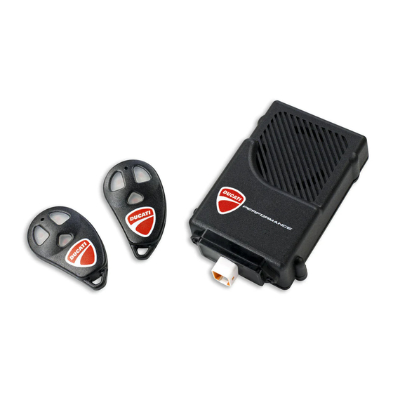
- Seite 2 Pos. Denominazione Description Supporto antivibrante Vibration damping support Centralina antifurto Anti-theft system control unit Telecomando Remote control Prolunga connessione antifurto Anti-theft system connection extension Fascetta ISTR 854 / 00...
- Seite 3 Smontaggio componenti originali Removing the original components (versioni Supersport) (Supersport versions) Smontaggio sella Seat disassembly Introdurre la chiave nella serratura (A1), ruotarla in senso orario e Insert the key in lock (A1), turn clockwise while pressing down at contemporaneamente premere verso il basso in prossimità del the latch to help release the pin.
- Seite 4 Smontaggio convogliatori Conveyor disassembly Svitare e recuperare le viti (B1) e (B2). Loosen and collect screws (B1) and (B2). Traslare il convogliatore sinistro (B) verso la parte posteriore del Shift the LH conveyor (B) towards the rear side of the motorcycle motoveicolo e sollevare verso l’alto sganciando le n.2 linguette (B3) and lift it up after releasing the 2 tabs (B3) from slots (D1) of the dalle asole (D1) del telaietto anteriore (D) e le n.2 linguette (B4)
- Seite 5 Smontaggio cover blocco chiave Removing the ignition switch cover Svitare i n.2 dadi speciali (G1) di fissaggio della cover blocco chiave Loosen no.2 special nuts (G1) fastening ignition switch cover (G). (G). Remove ignition switch cover (G). Rimuovere la cover blocco chiave (G). ISTR 854 / 00...
- Seite 6 ISTR 854 / 00...
- Seite 7 Smontaggio carena sinistra Removing the LH fairing Operando sul lato sinistro del motoveicolo, svincolare il tubo sfiato Working on the motorcycle left side, release the breather pipe (H) (H) dalla sede (C2) posta sulla parte inferiore della carena sinistra from its seat (C2) on the lower side of the LH fairing (C). (C).
- Seite 8 ISTR 854 / 00...
- Seite 9 Smontaggio carena destra Removing the RH fairing Operando sul lato destro del motoveicolo, svitare la vite (E5) Working on the RH side of the motorcycle, loosen the screw (E5) con distanziale con collare (E6) di fissaggio alla staffa inferiore di with spacer with collar (E6) retaining the fairing support lower sostegno carena.
- Seite 10 ISTR 854 / 00...
- Seite 11 Smontaggio serbatoio Removing the tank Operando da entrambi i lati del motoveicolo, svitare le n.2 viti (M1) Working from both sides of the motorcycle, loosen the 2 screws e svincolare i pioli (M2) posti sulla parte anteriore dei n.2 fianchetti (M1) and release the pins (M2) placed on the front part of the 2 (M) dai gommini antivibranti (L3), come mostrato nel riquadro (V), side panels (M) from vibration dampers (L3), as shown in the box...
- Seite 12 Sganciare l'elastico (N1) e rimuovere la borsa attrezzi (N2). Release elastic (N1) and remove the tool kit (N2). ISTR 854 / 00...
- Seite 13 Il cablaggio del motoveicolo è già predisposto per il collegamento The motorcycle wiring can be connected to the anti-theft system. dell'antifurto quindi occorre rimuovere il tappo (P2) dal connettore To this end it is necessary to remove plug (P2) from connector (P1) (P1) presente sulla parte sinistra del motoveicolo sopra la testa on the motorcycle left side above the vertical head.
- Seite 14 Smontaggio componenti originali Removing the original components (versioni Monster 1200) (Monster 1200 versions) Smontaggio sella Seat disassembly Introdurre la chiave nella serratura (A1), ruotarla in senso orario e Insert the key in lock (A1), turn clockwise while pressing down at contemporaneamente premere verso il basso in prossimità...
- Seite 15 Sganciare l'elastico (N1) e rimuovere la borsa attrezzi (N2). Release elastic (N1) and remove the tool kit (N2). ISTR 854 / 00...
- Seite 16 ISTR 854 / 00...
- Seite 17 Smontaggio cover blocco chiave Removing the ignition switch cover Svitare i n.2 dadi speciali (G1) di fissaggio della cover blocco chiave Loosen no.2 special nuts (G1) fastening ignition switch cover (G). (G). Remove ignition switch cover (G). Rimuovere la cover blocco chiave (G). Removing the tank Smontaggio serbatoio Release tank (L) front side by lifting lever (L3) and releasing hook...
- Seite 18 ISTR 854 / 00...
- Seite 19 Montaggio componenti kit (versioni Supersport) Kit installation (Supersport versions) Importante Caution Verificare, prima del montaggio, che tutti i componenti risultino Check that all components are clean and in perfect condition puliti e in perfetto stato. before installation. Adottare tutte le precauzioni necessarie per evitare di danneggiare Adopt any precaution necessary to avoid damages to any part of qualsiasi parte nella quale ci si trova ad operare.
- Seite 20 5 Nm ± 10% 3 Nm ± 10% 5 Nm ± 10% ISTR 854 / 00...
- Seite 21 Rimontaggio serbatoio Refitting the tank Note Notes Per una perfetta tenuta delle tubazioni carburante è consigliabile For a perfect seal of the fuel lines it is recommended to use new utilizzare fascette nuove. clamps. Riposizionare il serbatoio (L) sul motoveicolo, prestando attenzione Reposition tank (L) on motorcycle, paying attention not to damage a non rovinarlo.
- Seite 22 2,5 Nm ± 10% 2,5 Nm ± 10% 4 Nm ± 10% 2,5 Nm ± 10% ISTR 854 / 00...
- Seite 23 Rimontaggio carena destra Refitting the RH fairing Applicare lubrificante per gomma sui n.2 gommini antivibranti (D4), Apply lubricant for rubber on the 2 vibration dampers (D4), the sul gommino antivibrante (L2) e sul piolo (J2). vibration damper (L2) and pin (J2). Montare la carena destra (E) inserendo nell’ordine: Fit the RH fairing (E) by inserting the following components in this - il perno posteriore (E2) nel gommino antivibrante (L2);...
- Seite 24 2,5 Nm ± 10% 4 Nm ± 10% 2,5 Nm ± 10% 2,5 Nm ± 10% 2,5 Nm ± 10% ISTR 854 / 00...
- Seite 25 Rimontaggio carena sinistra Refitting the LH fairing Applicare lubrificante per gomma sui n.2 gommini antivibranti (D3), Apply lubricant for rubber on the 2 vibration dampers (D3), the sul gommino antivibrante (L1) e sul piolo (J1). vibration damper (L1) and pin (J1). Montare la carena sinistra (C) inserendo nell’ordine: Fit the LH fairing (C) by inserting the following components in this - il perno posteriore (C12) nel gommino antivibrante (L1);...
- Seite 26 7 Nm ± 10% Rimontaggio cover blocco chiave Refitting the ignition switch cover Posizionare la cover blocco chiave (G) inserendo nei fori delle n.2 Position ignition switch cover (G) by inserting the threaded stud poppette (G2), le colonnette filettate (D7). bolts (D7) into the holes of no.2 poppets (G2).
- Seite 27 4 Nm ± 10% 0,5 Nm ± 10% Rimontaggio convogliatore destro Refitting RH conveyor Posizionare il convogliatore destro (F) inserendone i n.2 denti Position the RH conveyor (F) by inserting its 2 front teeth (F3) into anteriori (F3) nelle asole (D2) del telaietto anteriore (D) ed i n. 2 slots (D2) of the front subframe (D) and the 2 teeth (F4) into slots denti (F4) nelle asole (E1) della carena destra (E).
- Seite 28 4 Nm ± 10% 0,5 Nm ± 10% Rimontaggio convogliatore sinistro Refitting LH conveyor Posizionare il convogliatore sinistro (B) inserendone i n.2 denti Position the LH conveyor (B) by inserting its 2 front teeth (B3) into anteriori (B3) nelle asole (D1) del telaietto anteriore (D) ed i n. 2 slots (D1) of the front subframe (D) and the 2 teeth (B4) into slots denti (B4) nelle asole (C1) della carena sinistra (C).
- Seite 29 Note Notes Prima di rimontare la sella occorre eseguire la procedura di Before refitting seat, carry out the anti-theft system activation attivazione antifurto (vedi pagina 36). procedure (see page 36). Rimontaggio sella Refitting the seat Assicurarsi che tutti gli elementi siano correttamente disposti e Make sure that all parts are correctly arranged and secured in the fissati nel vano sotto la sella (A).
- Seite 30 ISTR 854 / 00...
- Seite 31 Montaggio componenti kit Kit installation (Monster 1200 versions) (versioni Monster 1200) Caution Check that all components are clean and in perfect condition Importante before installation. Verificare, prima del montaggio, che tutti i componenti risultino Adopt any precaution necessary to avoid damages to any part of puliti e in perfetto stato.
- Seite 32 5 Nm ± 10% ISTR 854 / 00...
- Seite 33 Rimontaggio serbatoio Refitting the tank Note Notes Per una perfetta tenuta delle tubazioni carburante è consigliabile For a perfect seal of the fuel lines it is recommended to use new utilizzare fascette nuove. clamps. Accertarsi del corretto posizionamento del tampone in gomma Make sure rubber block (L10) is correctly positioned.
- Seite 34 7 Nm ± 10% Rimontaggio cover blocco chiave Refitting the ignition switch cover Posizionare la cover blocco chiave (G) inserendo nei fori delle n.2 Position ignition switch cover (G) by inserting the threaded stud poppette (G2), le colonnette filettate (D7). bolts (D7) into the holes of no.2 poppets (G2).
- Seite 35 Note Notes Prima di rimontare la sella occorre eseguire la procedura di Before refitting seat, carry out the anti-theft system activation attivazione antifurto (vedi pagina 36). procedure (see page 36). Rimontaggio sella Refitting the seat Assicurarsi che tutti gli elementi siano correttamente disposti e Make sure that all parts are correctly arranged and secured in the fissati nel vano sotto la sella (A).
- Seite 36 ISTR 854 / 00...
- Seite 37 Attivazione/Disattivazione antifurto Anti-theft system enabling/disabling Collegare lo strumento di diagnosi al connettore acquisizione dati. Connect the diagnostic tool to the data acquisition socket. Selezionare il modello corretto di motoveicolo. Select the correct motorcycle model. Selezionare l’ambiente “Self-diagnosis” (T1) nel menù a sinistra e Select “Self-diagnosis”...
- Seite 38 Supersport Monster 1200 Telecomandi Remote controls Importante Caution In dotazione al kit antifurto vengono forniti n.2 telecomandi Within the antitheft system kit you are provided with no. 2 remote (3); la capacità massima di gestione del sistema antifurto è n.8 controls (3).
- Seite 39 Condizione partendo dal sistema di allarme NON inserito Condition with DISABLED alarm system A sistema disinserito, (moto parcheggiata senza allarme attivato) With disabled system, (parked motorcycle with disabled alarm) trascorso il periodo di 36 ore il sistema entra in modalità Stand-by. after 36 hours the system switches to Stand-by mode.
- Seite 40 Esclusione sirena Siren alarm disabling Durante i primi 5 secondi d'inserimento (led sul cruscotto During the first 5 seconds after enabling the system (dashboard acceso fisso) premendo il tasto (3B) del telecomando è possibile LED steady on) it is possible to disable the siren by pressing button escludere il funzionamento della sirena.
- Seite 41 Attenzione Warning Nel caso venga acceso il quadro del veicolo (key-on) o venga When vehicle instrument panel is switched on (key-on) or if premuto il tasto (3B) del telecomando (allarme panico), il suono button (3B) on remote control is pressed (panic alarm), the siren is della sirena viene ripristinato.
- Seite 42 Memorizzazione nuovi telecomandi Storing new remote controls Importante Caution In caso di problematiche nella realizzazione della seguente In case of problems in implementing the following procedure, procedura prego contattare i seguenti numeri please call the phone numbers below: telefonici: - ITALY: 848 800981 (toll free); - ITALIA: 848 800981 (numero verde);...
- Seite 43 Questa operazione permette di personalizzare il codice segreto di This procedure allows you to customise the secret override code sblocco da quello di fabbrica (1-2-3) a quello desiderato, seguendo and pass from the factory-set one (1-2-3) to your own; proceed as questa procedura: follows: - Da cruscotto comporre il codice segreto come descritto nel...
- Seite 44 NOTE / NOTES ISTR 854 / 00...
- Seite 45 ISTR - 854 / 00 96680611A Kit antivol Kit Diebstahlsicherung Symboles Symbole Pour faciliter la consultation de ce manuel, des symboles signalent Zum schnellen und übersichtlichen Lesen werden Symbole des situations exigeant le maximum d'attention, des conseils verwendet, die außerordentlich wichtige Situationen, praktische pratiques ou de simples informations.
- Seite 46 Pos. Designation Bezeichnung Support antivibratoire Schwingungsdämpfender Halter Boîtier électronique antivol Steuergerät der Diebstahlsicherung Télécommande Fernbedienung Rallonge connexion antivol Verlängerung der Diebstahlsicherungsverbindung Collier serre-flex Schelle ISTR 854 / 00...
- Seite 47 Dépose composants d'origine Ausbau der Original-Bestandteile (versions Supersport) (Versionen Supersport) Dépose de la selle Abnahme der Sitzbank Introduire la clé dans la serrure (A1), la tourner dans le sens des Den Schlüssel in das Schloss (A1) stecken, im Uhrzeigersinn aiguilles d'une montre en poussant vers le bas à proximité du drehen und gleichzeitig am Schlossriegel nach unten drücken, um verrou pour faciliter le décrochage de la vis sans tête.
- Seite 48 Dépose des déflecteurs Abnahme der Luftleitkanäle Desserrer et récupérer les vis (B1) et (B2). Die Schrauben (B1) und (B2) lösen und aufnehmen. Déplacer le déflecteur gauche (B) vers l’arrière du motocycle Den linken Luftleitkanal (B) zum Motorradheck schieben und et lever en décrochant les 2 languettes (B3) des crans (D1) du anheben, dabei die 2 Laschen (B3) von den Langlöchern (D1) des sous-cadre avant (D) et les 2 languettes (B4) des crans (C1) de vorderen Rahmenaufsatzes (D) und die 2 Laschen (B4) von den...
- Seite 49 Dépose du cover barillet clé de contact Abnahme der Zündschlüsselblockabdeckung Desserrer les 2 écrous spéciaux (G1) de fixation du cache barillet Die 2 Spezialmuttern (G1) der Befestigung der clé de contact (G). Zündschlüsselblockabdeckung (G) lösen. Déposer le cache barillet clé de contact (G). Die Zündschlüsselblockabdeckung (G) entfernen.
- Seite 50 ISTR 854 / 00...
- Seite 51 Dépose carénage gauche Abnahme der linken Verkleidung En agissant du côté gauche du motocycle, dégager la durite An der linken Seite des Motorrads den Entlüftungsschlauch (H) aus reniflard (H) du logement (C2) situé dans la partie inférieure du dem Sitz (C2) im unteren Teil der linken Verkleidung (C) lösen. carénage gauche (C).
- Seite 52 ISTR 854 / 00...
- Seite 53 Dépose carénage droit Abnahme der rechten Verkleidung En agissant du côté droit du motocycle, desserrer la vis (E5) avec An der rechten Seite des Motorrads die Schraube (E5) mit entretoise à collerette (E6) de fixation à la bride inférieure de Distanzstück mit Bund (E6) der Befestigung am unteren Stützbügel support carénage.
- Seite 54 ISTR 854 / 00...
- Seite 55 Dépose du réservoir Abnahme des Tanks En intervenant des deux côtés du motocycle, desserrer les 2 vis An beiden Seiten des Motorrads die 2 Schrauben (M1) lösen (M1) et dégager les vis sans tête (M2) situées sur la partie avant und die Stifte (M2) am vorderen Teil der 2 Seitenabdeckungen des 2 flancs de carénage (M) des plots antivibratoires (L3), comme (M), wie in Detailausschnitt (V) abgebildet, aus den...
- Seite 56 Décrocher l'élastique (N1) et retirer la trousse à outils (N2). Den Spanngummi (N2) aushaken und die Werkzeugtasche (N2) entfernen. ISTR 854 / 00...
- Seite 57 Le câblage du motocycle est déjà prédisposé pour le raccordement Die Verkabelung des Motorrads ist bereits für den Anschluss der de l'antivol, il faut donc enlever le bouchon (P2) du connecteur (P1) Diebstahlsicherung ausgelegt, daher braucht nur die Kappe (P2) présent sur la partie gauche du motocycle sur la culasse verticale.
- Seite 58 Dépose composants d'origine Ausbau der Original-Bestandteile (versions Monster 1200) (Versionen Monster 1200) Dépose de la selle Abnahme der Sitzbank Introduire la clé dans la serrure (A1), la tourner dans le sens des Den Schlüssel in das Schloss (A1) stecken, im Uhrzeigersinn aiguilles d'une montre en poussant vers le bas à...
- Seite 59 Décrocher l'élastique (N1) et retirer la trousse à outils (N2). Den Spanngummi (N2) aushaken und die Werkzeugtasche (N2) entfernen. ISTR 854 / 00...
- Seite 60 ISTR 854 / 00...
- Seite 61 Dépose du cover barillet clé de contact Abnahme der Zündschlüsselblockabdeckung Desserrer les 2 écrous spéciaux (G1) de fixation du cache barillet Die 2 Spezialmuttern (G1) der Befestigung der clé de contact (G). Zündschlüsselblockabdeckung (G) lösen. Déposer le cache barillet clé de contact (G). Die Zündschlüsselblockabdeckung (G) entfernen.
- Seite 62 ISTR 854 / 00...
- Seite 63 Pose composants kit (versions Supersport) Montage der Komponenten des Kits (Versionen Supersport) Important Vérifier, avant la pose, que tous les composants sont propres et en Wichtig parfait état. Vor der Montage überprüfen, dass sich alle Komponenten im Adopter toutes les précautions nécessaires pour éviter sauberen und perfekten Zustand befinden.
- Seite 64 5 Nm ± 10% 3 Nm ± 10% 5 Nm ± 10% ISTR 854 / 00...
- Seite 65 Repose du réservoir Montage des Tanks Remarques Hinweis Pour une parfaite étanchéité des tubulures carburant il est conseillé Für den perfekten Halt der Kraftstoffleitungen wird empfohlen, d’utiliser des colliers neufs. neue Schellen zu verwenden. Repositionner le réservoir (L) sur le motocycle en faisant attention Den Tank (L) erneut am Motorrad anordnen und dabei darauf à...
- Seite 66 2,5 Nm ± 10% 2,5 Nm ± 10% 4 Nm ± 10% 2,5 Nm ± 10% ISTR 854 / 00...
- Seite 67 Repose carénage droit Montage der rechten Verkleidung Appliquer du lubrifiant pour caoutchouc sur les 2 plots Auf den 2 Schwingungsdämpfergummis (D4), den antivibratoires (D4), sur le plot antivibratoire (L2) et sur la vis sans Schwingungsdämpfergummi (L2) und den Stift (J2) Schmiermittel tête (J2).
- Seite 68 2,5 Nm ± 10% 4 Nm ± 10% 2,5 Nm ± 10% 2,5 Nm ± 10% 2,5 Nm ± 10% ISTR 854 / 00...
- Seite 69 Repose carénage gauche Montage der linken Verkleidung Appliquer du lubrifiant pour caoutchouc sur les 2 plots Auf den 2 Schwingungsdämpfergummis (D3), den antivibratoires (D3), sur le plot antivibratoire (L1) et sur la vis sans Schwingungsdämpfergummi (L1) und den Stift (J1) Schmiermittel tête (J1).
- Seite 70 7 Nm ± 10% Repose du cover barillet clé de contact Montage der Zündschlüsselblockabdeckung Positionner le cache barillet clé de contact (G) en insérant dans les Die Zündschlüsselblockabdeckung (G) anordnen, dazu die trous des 2 douilles (G2) les goujons filetés (D7). Gewindestifte (D7) in die Bohrungen der 2 Nippel (G2) einfügen.
- Seite 71 4 Nm ± 10% 0,5 Nm ± 10% Repose déflecteur droit Montage des rechten Luftleitkanals Positionner le déflecteur droit (F) en insérant les 2 dents avant Den rechten Luftleitkanal (F) anordnen, dazu die 2 vorderen Zähne (F3) dans les crans (D2) du sous-cadre avant (D) et les 2 dents (F4) (F3) in die Langlöcher (D2) des vorderen Rahmenaufsatzes (D) und dans les crans (E1) du carénage droit (E).
- Seite 72 4 Nm ± 10% 0,5 Nm ± 10% Repose déflecteur gauche Montage des linken Luftleitkanals Positionner le déflecteur gauche (B) en insérant les 2 dents avant Den linken Luftleitkanal (B) anordnen, dazu die 2 vorderen Zähne (B3) dans les crans (D1) du sous-cadre avant (D) et les 2 dents (B4) (B3) in die Langlöcher (D1) des vorderen Rahmenaufsatzes (D) und dans les crans (C1) du carénage gauche (C).
- Seite 73 Remarques Hinweis Avant de reposer la selle, il faut effectuer la procédure d’activation Vor der erneuten Montage der Sitzbank muss das antivol (voir page 36). Aktivierungsverfahren der Diebstahlsicherung (siehe Seite 36) vorgenommen werden. Repose selle Montage der Sitzbank Vérifier que tous les éléments sont correctement placés et fixés dans le dégagement sous la selle (A).
- Seite 74 ISTR 854 / 00...
- Seite 75 Pose composants kit (versions Monster 1200) Montage der Komponenten des Kits (Versionen Monster 1200) Important Vérifier, avant la pose, que tous les composants sont propres et en Wichtig parfait état. Vor der Montage überprüfen, dass sich alle Komponenten im Adopter toutes les précautions nécessaires pour éviter sauberen und perfekten Zustand befinden.
- Seite 76 5 Nm ± 10% ISTR 854 / 00...
- Seite 77 Repose du réservoir Montage des Tanks Remarques Hinweis Pour une parfaite étanchéité des tubulures carburant il est conseillé Für den perfekten Halt der Kraftstoffleitungen wird empfohlen, d’utiliser des colliers neufs. neue Schellen zu verwenden. S'assurer du positionnement correct du tampon en caoutchouc Sicherstellen, dass der Gummistopfen (L10) korrekt angeordnet ist.
- Seite 78 7 Nm ± 10% Repose du cover barillet clé de contact Montage der Zündschlüsselblockabdeckung Positionner le cache barillet clé de contact (G) en insérant dans les Die Zündschlüsselblockabdeckung (G) anordnen, dazu die trous des 2 douilles (G2) les goujons filetés (D7). Gewindestifte (D7) in die Bohrungen der 2 Nippel (G2) einfügen.
- Seite 79 Remarques Hinweis Avant de reposer la selle, il faut effectuer la procédure d’activation Vor der erneuten Montage der Sitzbank muss das antivol (voir page 36). Aktivierungsverfahren der Diebstahlsicherung (siehe Seite 36) vorgenommen werden. Repose selle Montage der Sitzbank Vérifier que tous les éléments soient correctement placés et fixés dans le compartiment dessous de selle (A).
- Seite 80 ISTR 854 / 00...
- Seite 81 Activation/désactivation système antivol Aktivierung/Deaktivierung der Diebstahlsicherung Relier l'instrument de diagnostic au connecteur de saisie de Das Diagnoseinstrument an den Datenerfassungsanschluss données. schließen. Sélectionner le modèle de motocycle souhaité. Das korrekte Motorradmodell wählen. Sélectionner l'environnement « Self-diagnosis » (T1) dans le menu Im links stehenden Menü...
- Seite 82 Supersport Monster 1200 Télécommandes Fernbedienungen Important Wichtig Le kit antivol est fourni avec n. 2 télécommandes (3) ; la capacité Im Lieferumfang des Kits der Diebstahlsicherung sind maximale de gestion du système antivol est de n. 8 2 Fernbedienungen (3) enthalten. Das System der télécommandes.
- Seite 83 État depuis le système d'alarme DÉSACTIVÉ Von einem NICHT eingeschaltetem Alarmsystem ausgehende Bedingung Le système désactivé (moto garée sans alarme active), après 36 heures le système entre en mode Stand-by. Il n'est plus possible Bei ausgeschaltetem System (abgeparktes Motorrad ohne d'insérer l'alarme car le récepteur est désactivé...
- Seite 84 Désactivation de la sirène Ausschluss der Alarmsirene Pendant les 5 premières secondes d'activation, (led sur le Während der ersten 5 Sekunden nach dem Einschalten (LED tableau de bord allumée fixe), il est possible de désactiver le im Cockpit leuchtet permanent) kann durch Drücken der Taste fonctionnement de la sirène en appuyant sur la touche (3B) de la (3B) der Fernbedienung die Funktion der Sirene ausgeschlossen télécommande.
- Seite 85 Attention Achtung Au cas où le tableau de bord du véhicule serait allumé (key - on) Sollte das Cockpit des Fahrzeugs eingeschaltet (key-on) oder die ou la touche (3B) de la télécommande (alarme panique) serait Taste (3B) der Fernbedienung gedrückt werden (Panik-Alarm), wird enfoncée, le son de la sirène est rétabli.
- Seite 86 Mémorisation des télécommandes nouvelles. Speichern neuer Fernbedienungen Important Wichtig En cas de problèmes pendant l'exécution de la procédure suivante Im Falle von Problemen bei der Durchführung folgenden Vorgangs veuillez appeler les numéros de téléphone indiqués ci-après : bitten wir Sie, uns unter den nachstehenden Telefonnummern zu - ITALIE : 848 800981 (numéro vert) ;...
- Seite 87 Il est possible de personnaliser le code confidentiel de déblocage, Dieses Verfahren ermöglicht anhand des nachstehenden en modifiant le code d'usine (1-2-3) selon la procédure cidessous: Verfahrens die Eingabe eines persönlichen bzw. anderen als den - Depuis le tableau de bord taper le code confidentiel, comme werksintern eingegebenen Freigabecode (1-2-3): décrit au paragraphe précédent.
- Seite 88 REMARQUES / HINWEIS ISTR 854 / 00...
- Seite 89 ISTR - 854 / 00 96680611A Conjunto dispositivo anti-roubo Anti-theft system kit Símbolos Symbols Para uma leitura rápida e racional, foram utilizados símbolos que To allow quick and easy consultation, this manual uses graphic evidenciam situações de máxima atenção, conselhos práticos ou symbols to highlight situations in which maximum care is required, simples informações.
- Seite 90 Pos. Descrição Description Suporte antivibrações Vibration damping support Unidade eletrónica anti-roubo Anti-theft system control unit Telecomando Remote control Extensão da conexão do dispositivo antirroubo Anti-theft system connection extension Braçadeira ISTR 854 / 00...
- Seite 91 Desmontagem dos componentes originais Removing the original components (versões Supersport) (Supersport versions) Desmontagem do assento Seat disassembly Introduza a chave na fechadura (A1), gire-a no sentido horário e, Insert the key in lock (A1), turn clockwise while pressing down at simultaneamente, pressione para baixo perto do trinco para facilitar the latch to help release the pin.
- Seite 92 Desmontagem das condutas Conveyor disassembly Desatarraxe e guarde os parafusos (B1) e (B2). Loosen and collect screws (B1) and (B2). Desloque a conduta esquerda (A) para a parte traseira da moto Shift the LH conveyor (B) towards the rear side of the motorcycle e levante desengatando as 2 linguetas (B3) dos olhais (D1) do and lift it up after releasing the 2 tabs (B3) from slots (D1) of the subchassi dianteiro (D) e as 2 linguetas (B4) dos olhais (C1) do...
- Seite 93 Desmontagem da cobertura do canhão da chave Removing the ignition switch cover Desatarraxe as 2 porcas especiais (G1) de fixação da cobertura do Loosen no.2 special nuts (G1) fastening ignition switch cover (G). canhão da chave (G). Remove ignition switch cover (G). Remova a cobertura do canhão da chave (G).
- Seite 94 ISTR 854 / 00...
- Seite 95 Desmontagem da carenagem esquerda Removing the LH fairing Atuando no lado esquerdo da moto, soltes o tubo de purga (H) da Working on the motorcycle left side, release the breather pipe (H) sede (C2) situada na parte inferior da carenagem esquerda (C). from its seat (C2) on the lower side of the LH fairing (C).
- Seite 96 ISTR 854 / 00...
- Seite 97 Desmontagem da carenagem direita Removing the RH fairing Atuando no lado direito da moto, desatarraxe o parafuso (E5) com Working on the RH side of the motorcycle, loosen the screw (E5) o espaçador com colar (E6) de fixação à braçadeira inferior de with spacer with collar (E6) retaining the fairing support lower sustentação da carenagem.
- Seite 98 ISTR 854 / 00...
- Seite 99 Desmontagem do depósito Removing the tank Atuando de ambos os lados da moto, desatarraxe os 2 parafusos Working from both sides of the motorcycle, loosen the 2 screws (M1) e solte os pinos (M2) situados na parte dianteira dos 2 flancos (M1) and release the pins (M2) placed on the front part of the 2 (M) das borrachas antivibrações (L3), como mostrado no quadro side panels (M) from vibration dampers (L3), as shown in the box...
- Seite 100 Desengate o elástico (N1) e remova a bolsa de ferramentas (N2). Release elastic (N1) and remove the tool kit (N2). ISTR 854 / 00...
- Seite 101 A cablagem da moto já está preparada para a ligação do dispositivo The motorcycle wiring can be connected to the anti-theft system. anti-roubo; portanto, é preciso remover a tampa (P2) do conector To this end it is necessary to remove plug (P2) from connector (P1) (P1) presente na parte esquerda da moto acima da cabeça vertical.
- Seite 102 Desmontagem dos componentes originais Removing the original components (versões Monster 1200) (Monster 1200 versions) Desmontagem do assento Seat disassembly Introduza a chave na fechadura (A1), gire-a no sentido horário e, Insert the key in lock (A1), turn clockwise while pressing down at simultaneamente, pressione para baixo perto do trinco para facilitar the latch to help release the pin.
- Seite 103 Desengate o elástico (N1) e remova a bolsa de ferramentas (N2). Release elastic (N1) and remove the tool kit (N2). ISTR 854 / 00...
- Seite 104 ISTR 854 / 00...
- Seite 105 Desmontagem da cobertura do canhão da chave Removing the ignition switch cover Desatarraxe as 2 porcas especiais (G1) de fixação da cobertura do Loosen no.2 special nuts (G1) fastening ignition switch cover (G). canhão da chave (G). Remove ignition switch cover (G). Remova a cobertura do canhão da chave (G).
- Seite 106 ISTR 854 / 00...
- Seite 107 Montagem dos componentes Kit installation (Supersport versions) (versões Supersport) Caution Check that all components are clean and in perfect condition Importante before installation. Verifique, antes da montagem, se todos os componentes estão Adopt any precaution necessary to avoid damages to any part of limpos e em perfeito estado.
- Seite 108 5 Nm ± 10% 3 Nm ± 10% 5 Nm ± 10% ISTR 854 / 00...
- Seite 109 Remontagem do depósito Refitting the tank Notas Notes Para uma vedação perfeita das tubagens de combustível, For a perfect seal of the fuel lines it is recommended to use new aconselha-se a utilização de braçadeiras novas. clamps. Posicione o depósito (L) na moto, prestando atenção para não o Reposition tank (L) on motorcycle, paying attention not to damage danificar.
- Seite 110 2,5 Nm ± 10% 2,5 Nm ± 10% 4 Nm ± 10% 2,5 Nm ± 10% ISTR 854 / 00...
- Seite 111 Remontagem da carenagem direita Refitting the RH fairing Aplique lubrificante para borracha nas 2 borrachas antivibrações Apply lubricant for rubber on the 2 vibration dampers (D4), the (D4), na borracha antivibrações (L2) e no pino (J2). vibration damper (L2) and pin (J2). Monte a carenagem direita (E), inserindo na ordem: Fit the RH fairing (E) by inserting the following components in this - o perno traseiro (E2) na borracha antivibrações (L2);...
- Seite 112 2,5 Nm ± 10% 4 Nm ± 10% 2,5 Nm ± 10% 2,5 Nm ± 10% 2,5 Nm ± 10% ISTR 854 / 00...
- Seite 113 Remontagem da carenagem esquerda Refitting the LH fairing Aplique lubrificante para borracha nas 2 borrachas antivibrações Apply lubricant for rubber on the 2 vibration dampers (D3), the (D3), na borracha antivibrações (L1) e no pino (J1). vibration damper (L1) and pin (J1). Monte a carenagem esquerda (C), inserindo na ordem: Fit the LH fairing (C) by inserting the following components in this - o perno traseiro (C12) na borracha antivibrações (L1);...
- Seite 114 7 Nm ± 10% Remontagem da cobertura do canhão da chave Refitting the ignition switch cover Posicione a cobertura do canhão da chave (G), inserindo nos furos Position ignition switch cover (G) by inserting the threaded stud das 2 extremidades (G2), as colunas roscadas (D7). bolts (D7) into the holes of no.2 poppets (G2).
- Seite 115 4 Nm ± 10% 0,5 Nm ± 10% Remontagem da conduta direita Refitting RH conveyor Posicione a conduta direita (F) inserindo os 2 dentes dianteiros (F3) Position the RH conveyor (F) by inserting its 2 front teeth (F3) into nos olhais (D2) do subchassis dianteiro (D) e os 2 dentes (F4) nos slots (D2) of the front subframe (D) and the 2 teeth (F4) into slots olhais (E1) da carenagem esquerda (E).
- Seite 116 4 Nm ± 10% 0,5 Nm ± 10% Remontagem da conduta esquerda Refitting LH conveyor Posicione a conduta esquerda (B) inserindo os 2 dentes dianteiros Position the LH conveyor (B) by inserting its 2 front teeth (B3) into (B3) nos olhais (D1) do subchassis dianteiro (D) e os 2 dentes (B4) slots (D1) of the front subframe (D) and the 2 teeth (B4) into slots nos olhais (C1) da carenagem esquerda (C).
- Seite 117 Notas Notes Antes de voltar a montar o assento, é necessário efetuar o Before refitting seat, carry out the anti-theft system activation procedimento de ativação do dispositivo antirroubo (veja a página procedure (see page 36). 36). Refitting the seat Remontagem do assento Make sure that all parts are correctly arranged and secured in the Certifique-se de que todos os elementos estão corretamente compartment under the seat (A).
- Seite 118 ISTR 854 / 00...
- Seite 119 Montagem dos componentes Kit installation (Monster 1200 versions) (versões Monster 1200) Caution Check that all components are clean and in perfect condition Importante before installation. Verifique, antes da montagem, se todos os componentes estão Adopt any precaution necessary to avoid damages to any part of limpos e em perfeito estado.
- Seite 120 5 Nm ± 10% ISTR 854 / 00...
- Seite 121 Remontagem do depósito Refitting the tank Notas Notes Para uma vedação perfeita das tubagens de combustível, For a perfect seal of the fuel lines it is recommended to use new aconselha-se a utilização de braçadeiras novas. clamps. Certifique-se do correto posicionamento do tampão de borracha Make sure rubber block (L10) is correctly positioned.
- Seite 122 7 Nm ± 10% Remontagem da cobertura do canhão da chave Refitting the ignition switch cover Posicione a cobertura do canhão da chave (G), inserindo nos furos Position ignition switch cover (G) by inserting the threaded stud das 2 extremidades (G2), as colunas roscadas (D7). bolts (D7) into the holes of no.2 poppets (G2).
- Seite 123 Notas Notes Antes de voltar a montar o assento, é necessário efetuar o Before refitting seat, carry out the anti-theft system activation procedimento de ativação do dispositivo antirroubo (veja a página procedure (see page 36). 36). Refitting the seat Remontagem do assento Make sure that all parts are correctly arranged and secured in the Certifique-se de que todos os elementos estejam corretamente compartment under the seat (A).
- Seite 124 ISTR 854 / 00...
- Seite 125 Ativação/Desativação do dispositivo antirroubo Anti-theft system enabling/disabling Ligue o instrumento de diagnóstico ao conector de aquisição de Connect the diagnostic tool to the data acquisition socket. dados. Select the correct motorcycle model. Selecione o modelo correto de moto. Select “Self-diagnosis” (T1) from the menu on the left and then Selecione o ambiente “Self-diagnosis”...
- Seite 126 Supersport Monster 1200 TTelecomandos Remote controls Importante Caution Junto com o kit anti-roubo, são fornecidos n.2 telecomandos (3); Within the antitheft system kit you are provided with no. 2 remote A capacidade máxima de gestão do sistema anti-roubo é de 8 controls (3).
- Seite 127 Condição partindo do sistema de alarme NÃO ativado Condition with DISABLED alarm system Com o sistema desativado, (moto estacionada sem alarme ativado) With disabled system, (parked motorcycle with disabled alarm) transcorrido o período de 36 horas, o sistema entra no modo de after 36 hours the system switches to Stand-by mode.
- Seite 128 Desativação da sirene Siren alarm disabling Durante os primeiros 5 segundos da ativação (led no painel During the first 5 seconds after enabling the system (dashboard de instrumentos aceso fixo), pressionando a tecla (3B) do LED steady on) it is possible to disable the siren by pressing button telecomando, é...
- Seite 129 Atenção Warning Caso o quadro do veículo seja acendido (key-on) ou seja When vehicle instrument panel is switched on (key-on) or if pressionada a tecla (3B) do telecomando (alarme de pânico), o som button (3B) on remote control is pressed (panic alarm), the siren is da sirene é...
- Seite 130 Memorização dos novos telecomandos Storing new remote controls Importante Caution No caso de problemas na realização do procedimento a seguir, por In case of problems in implementing the following procedure, favor, contate os seguintes números telefónicos: please call the phone numbers below: - ITÁLIA: 848 800981 (número verde);...
- Seite 131 Esta operação permite personalizar o código secreto de This procedure allows you to customise the secret override code desbloqueio daquele de fábrica (1-2-3) para aquele desejado, and pass from the factory-set one (1-2-3) to your own; proceed as seguindo este procedimento: follows: - Através do painel de instrumentos, componha o código secreto - From the instrument panel, enter the secret code as described in...
- Seite 132 NOTAS / NOTES ISTR 854 / 00...
- Seite 133 ISTR - 854 / 00 96680611A Kit antirrobo 盗難防止キット Símbolos シンボル Para una lectura rápida y racional se han empleado símbolos que 素早くかつ合理的に読み進めることができるように、本マニュア evidencian situaciones de máxima atención, consejos prácticos o ルではいくつかのシンボルを導入し、最大限の注意を払う必要が simples informaciones. Prestar mucha atención al significado de ある状況や、推奨事項、または一般情報を明確にしてあります。...
- Seite 134 Pos. Denominacion 説明 Soporte antivibrante 耐震ダンパーマウント Central antirrobo 盗難防止コントロールユニット Mando a distancia リモコン Prolongación conexión antirrobo 盗難防止装置接続延長ケーブル Abrazadera クランプ ISTR 854 / 00...
- Seite 135 Desmontaje componentes originales オリジナル部品の取り外し (versiones Supersport) (Supersport バージョン) Desmontaje asiento シートの取り外し Introducir la llave en la cerradura (A1), girarla en el sentido de las ロック (A1) にキーを差し込み、時計回りに回しま す。同時にラ ッチ付近を下に押し、ピンを外しやすくします。 agujas del reloj y contemporáneamente presionar hacia abajo cerca del pestillo para facilitar la liberación del perno. シート...
- Seite 136 Desmontaje encanaladores エアコンベヤーの取り外し Desatornillar y recuperar los tornillos (B1) y (B2). スクリュー (B1) および (B2) を外して回収します。 Desplazar el encanalador izquierdo (B) hacia la parte trasera 左エアコンベヤー (B) を車両後方に動かします。2 個のタブ de la motocicleta y moverlo hacia arriba desenganchando las 2 (B3) をフロントサブフレーム (D) の溝 (D1) から、2 個のタブ lengüetas (B3) de los ojales (D1) del subchasis delantero (D) y las 2 (B4) を左フェアリングユニット...
- Seite 137 Desmontaje cover bloque llave イグニッションスイッチカバーの取り外し Desatornillar las 2 tuercas especiales (G1) de fijación del cover イグニッションスイッチカバー (G) を固定している 2 個の専用 bloque llave (G). ナット (G1) を緩めて外します。 Quitar el cover bloque llave (G). イグニッションスイッチカバー (G) を取り外します。 ISTR 854 / 00...
- Seite 138 ISTR 854 / 00...
- Seite 139 Desmontaje carenado izquierdo 左フェアリングの取り外し Operando en el lado izquierdo de la motocicleta, liberar el tubo 車両の左側で作業します。ブリーザーホース (H) を左フェアリン de alivio (H) del alojamiento (C2) situado en la parte inferior del グ (C) 下部の所定の位置 (C2) から引き抜きます。 carenado izquierdo (C). 左フェアリング (C) 下部の 2 本の固定スクリュー (C3) を 2 個 Desatornillar los 2 tornillos (C3) con 2 arandelas (C4) de nylon, de のナイロンワッシャー...
- Seite 140 ISTR 854 / 00...
- Seite 141 Desmontaje carenado derecho 右フェアリングの取り外し Desde el lado derecho de la motocicleta, desatornillar el tornillo 車両の右側で作業し、フェアリングロアブラケットに固定してい (E5) con separador con collar (E6) de fijación al sostén inferior de るスクリュー (E5) をカラー付きスペーサー (E6) と一緒に外し apoyo carenado. ます。 Desatornillar el tornillo (E7) de fijación al sostén lateral apoyo フェアリングサイドブラケットに固定しているスクリュー...
- Seite 142 ISTR 854 / 00...
- Seite 143 Desmontaje depósito フューエルタンクの取り外し Operando de ambos lados de la motocicleta, desatornillar los 2 車両の両側で作業します。2 本のスクリュー (M1) を緩めて外 tornillos (M1) y liberar los pernos (M2) en la parte delantera de し、枠内 (V) に示すように、2 つのサイドパネル (M) の前部に los 2 carenados laterales (M) de las juntas antivibrantes (L3), あるピン...
- Seite 144 Desenganchar el elástico (N1) y quitar la bolsa herramientas (N2). ゴム (N1) を外し、ツールバッグ (N2) を取 り外します。 ISTR 854 / 00...
- Seite 145 El cableado de la motocicleta ya está predispuesto para la 車両の配線はすでに盗難防止の接続ができるようになっていま conexión del antirrobo, por lo tanto, solo es necesario quitar el す。 tapón (P2) del conector (P1), en la parte izquierda del vehículo, したがって、車両の左側、バーチカルヘッドの上にあるコネクタ arriba de la culata vertical. ー...
- Seite 146 Desmontaje componentes originales オリジナル部品の取り外し (versiones Monster 1200) (Monster 1200 バージョン) Desmontaje asiento シートの取り外し Introducir la llave en la cerradura (A1), girarla en el sentido de las ロック (A1) にキーを差し込み、時計回りに回しま す。同時にラ ッチ付近を下に押し、ピンを外しやすくします。 agujas del reloj y contemporáneamente presionar hacia abajo cerca del pestillo para facilitar la liberación del perno.
- Seite 147 Desenganchar el elástico (N1) y quitar la bolsa herramientas (N2). ゴム (N1) を外し、ツールバッグ (N2) を取 り外します。 ISTR 854 / 00...
- Seite 148 ISTR 854 / 00...
- Seite 149 Desmontaje cover bloque llave イグニッションスイッチカバーの取り外し Desatornillar las 2 tuercas especiales (G1) de fijación del cover イグニッションスイッチカバー (G) を固定している 2 個の専用 bloque llave (G). ナット (G1) を緩めて外します。 Quitar el cover bloque llave (G). イグニッションスイッチカバー (G) を取り外します。 Desmontaje depósito フューエルタンクの取り外し Liberar la parte delantera del depósito (L) levantando la palanca (L3) レバー...
- Seite 150 ISTR 854 / 00...
- Seite 151 Montaje componentes kit (versiones Supersport) キット部品の取り付け (Supersport バージョン) Importante 重要 Controlar, antes del montaje, que todos los componentes se 取り付け前にすべての部品に汚れがなく、完璧な状態であること encuentren limpios y en perfecto estado. を確認します。 作業する部品の外側表面を傷つけないために、必要な予防措置を Adoptar todas las precauciones necesarias para evitar daños en la superficie exterior de los componentes donde se debe operar. 取ってください...
- Seite 152 5 Nm ± 10% 3 Nm ± 10% 5 Nm ± 10% ISTR 854 / 00...
- Seite 153 Montaje depósito フューエルタンクの取り付け Notas 参考 Para una perfecta estanqueidad del tubo combustible se 燃料ホースの密閉性を確保するために、新品のクランプを使用す recomienda utilizar abrazaderas nuevas. ることが推奨されます。 Volver a colocar el depósito (L) en la motocicleta prestando フューエルタンク (L) を破損しないように注意しながら車両に配 atención a no dañarlo. 置します。 Introducir las 2 abrazaderas (L8) en los extremos del tubo (L9) y del ホース...
- Seite 154 2,5 Nm ± 10% 2,5 Nm ± 10% 4 Nm ± 10% 2,5 Nm ± 10% ISTR 854 / 00...
- Seite 155 Montaje carenado derecho 右フェアリングの取り付け Aplicar lubricante para goma en las 2 juntas antivibrantes (D4), en 2 個の耐震ラバー (D4)、耐震ラバー (L2)、ピン (J2) にゴム用 la junta antivibrante (L2) y en el perno (J2). 潤滑剤を塗布します。 Montar el carenado derecho (E) introduciendo en orden: 以下の順序で挿入し、右フェアリング (E) を取り付けます。 - el perno trasero (E2) en la junta antivibrante (L2);...
- Seite 156 2,5 Nm ± 10% 4 Nm ± 10% 2,5 Nm ± 10% 2,5 Nm ± 10% 2,5 Nm ± 10% ISTR 854 / 00...
- Seite 157 Montaje carenado izquierdo 左フェアリングの取り付け Aplicar lubricante para goma en las 2 juntas antivibrantes (D3), en 2 個の耐震ラバー (D3)、耐震ラバー (L1)、ピン (J1) にゴム用 la junta antivibrante (L1) y en el perno (J1). 潤滑剤を塗布します。 Montar el carenado izquierdo (C) introduciendo en orden: 以下の順序で挿入し、左フェアリング (C) を取り付けます。 - el perno trasero (C12) en la junta antivibrante (L1);...
- Seite 158 7 Nm ± 10% Montaje cover bloque llave イグニッションスイッチカバーの取り付け Colocar el cover bloque llave (G) introduciendo las columnas de 2 つのポペット (G2) の穴にボルト (D7) を挿入して、イグニッ rosca (D7) en los orificios de los 2 extremos (G2). ションスイッチカバー (G) を配置します。 Fijar el cover bloque llave (G) introduciendo las 2 tuercas especiales 2 個の専用ナット...
- Seite 159 4 Nm ± 10% 0,5 Nm ± 10% Montaje encanalador derecho 右エアコンベヤーの取り付け Posicionar el encanalador derecho (F) introduciendo los 2 dientes 2 個の前側のタブ (F3) をフロントサブフレーム (D) の溝 (D2) delanteros (F3) en los ojales (D2) del subchasis delantero (D) y los に、2 個のタブ...
- Seite 160 4 Nm ± 10% 0,5 Nm ± 10% Montaje encalanador izquierdo 左エアコンベヤーの取り付け Posicionar el encanalador izquierdo (B) introduciendo los 2 dientes 2 個の前側のタブ (B3) をフロントサブフレーム (D) の溝 (D1) delanteros (B3) en los ojales (D1) del subchasis delantero (D) y los に、2 個のタブ...
- Seite 161 Notas 参考 Antes de montar nuevamente el asiento, es necesario realizar el シートを再び取り付ける前に、盗難防止装置のアクティベーショ procedimiento de activación antirrobo (véase página 36). ン手順を実施してください (ページ 36 参照)。 Montaje asiento シートの取り付け Asegurarse de que todos los elementos se encuentren すべてのエレメントが正しい位置にあり、シート (A) 下のボック correctamente dispuestos y fijados en el compartimiento debajo スに固定されていることを確認します。...
- Seite 162 ISTR 854 / 00...
- Seite 163 Montaje componentes kit キット部品の取り付け (versiones Monster 1200) (Monster 1200 バージョン) Importante 重要 Controlar, antes del montaje, que todos los componentes se 取り付け前にすべての部品に汚れがなく、完璧な状態であること encuentren limpios y en perfecto estado. を確認します。 作業する部品の外側表面を傷つけないために、必要な予防措置を Adoptar todas las precauciones necesarias para evitar daños en la superficie exterior de los componentes donde se debe operar.
- Seite 164 5 Nm ± 10% ISTR 854 / 00...
- Seite 165 Montaje depósito フューエルタンクの取り付け Notas 参考 Para una perfecta estanqueidad del tubo combustible se 燃料ホースの密閉性を確保するために、新品のクランプを使用す recomienda utilizar abrazaderas nuevas. ることが推奨されます。 Comprobar la colocación correcta del tapón de goma (L10). ラバーパッド (L10) が正しい位置に配置されていることを確認し Posicionar nuevamente el depósito (L) en la motocicleta, prestando ます。...
- Seite 166 7 Nm ± 10% Montaje cover bloque llave イグニッションスイッチカバーの取り付け Colocar el cover bloque llave (G) introduciendo las columnas de 2 つのポペット (G2) の穴にボルト (D7) を挿入して、イグニッ rosca (D7) en los orificios de los 2 extremos (G2). ションスイッチカバー (G) を配置します。 Fijar el cover bloque llave (G) introduciendo las 2 tuercas especiales 2 個の専用ナット...
- Seite 167 Notas 参考 Antes de montar nuevamente el asiento, es necesario realizar el シートを再び取り付ける前に、盗難防止装置のアクティベーショ procedimiento de activación antirrobo (véase página 36). ン手順を実施してください (ページ 36 参照)。 Montaje asiento シートの取り付け Asegurarse de que todos los elementos se encuentren すべてのエレメントが正しい位置にあり、シート (A) 下に固定さ correctamente dispuestos y fijados en el compartimiento debajo れていることを確認します。...
- Seite 168 ISTR 854 / 00...
- Seite 169 Activación/Desactivación antirrobo 盗難防止装置の起動/解除 Conectar el instrumento de diagnosis al conector de adquisición de 診断テスターをデータロガーコネクターに接続します。 datos. 正しい車両モデルを選択します。 Seleccionar el modelo correcto de motocicleta. 図 (X1) のように、左メニューから “Self-diagnosis” (自己診 Seleccionar el área “Self-diagnosis” (T1) en el menú a la izquierda, 断) 環境 (T1) を選択し、続いて “BBS” コマンド (T2) を選択 y sucesivamente el mando "BBS"...
-
Seite 170: Mandos A Distancia
Supersport Monster 1200 Mandos a distancia リモコン Importante 重要 Con el kit antirrobo vienen suministrados n. 2 mandos a distancia 防犯キットには2 つのリモコン(3) がついています。 (3). La capacidad máxima de gestión del sistema antirrobo es de n. 防犯システムは最大8 個までリモコンを管 理することができま 8 mandos a distancia. す。... - Seite 171 Condiciones partiendo con el sistema de alarma NO システムのアラームがOFF の場合 activado システムがOFF の場合、(アラームを起動 せずにバイクを停車し Con sistema desactivado (moto estacionada con alarma てから)36 時間後、 システムはStand-by モードに入ります。 desactivada), luego de 36 horas el sistema entra en modalidad 受信機が切れているのでアラームを起動す ることはできず、衝 Stand-by . Ya no es posible activar la alarma puesto que el receptor 突、盗難未遂、インス...
- Seite 172 Exclusión sirena サイレンの解除 Durante los primeros 5 segundos de activación (led en el 起動中の最初の5 秒間(インストルメント パネルのLED ランプ点 salpicadero encendido fijo), presionando el botón (3B) del mando a 灯)、リモコンのボ タン(3B)を押すことでサイレン機能を起動 distancia es posible desactivar el funcionamiento de la sirena. Dos させないことができます。ビープ音が2 回鳴り、サイレンが解除 señales acústicas avisan que se ha desactivado el されたことが伝え...
- Seite 173 Atención 注記 Si se enciende el cuadro del vehículo (key-on) o se presiona el 車両のインストルメントパネルが ON(key - on) されたり、リモ botón (3B) del mando a distancia (alarma de pánico), se restablece コンのボタン(3B)(パニックアラーム)が押されたりす ると、 el sonido de la sirena. サイレンがもう一度起動されます。 Alarma de pánico パニックアラーム...
- Seite 174 Memorización de nuevos mandos a distancia 新しいリモコンのメモリー Importante 重要 En caso de problemas al llevar a cabo el siguiente procedimiento, 以下の操作をおこなうにあたり問題 が生じた場合は、次のお問い por favor contactar los siguientes números telefónicos: 合わせ先まで ご連絡ください。 - ITALIA: 848 800981 (número gratuito); - イタリア国内から:848 800981(フリーダイヤル); - EXTRANJERO: +39 366 4966876.
- Seite 175 Esta operación permite personalizar el código secreto de 次の作業により、解除暗証番号を工場で設定されたもの(1-2-3) desbloqueo, cambiando el de fábrica (1-2-3) con uno deseado, から希望のものにパーソナライズすることができます。次の手順 siguiendo este procedimiento: で行います。 - Desde el salpicadero introducir el código secreto como se ha - インストルメントパネルから前のセクションの記載されている descrito en el párrafo anterior. 通り、暗証番号を入力します。...
- Seite 176 NOTAS / 参考 ISTR 854 / 00...
- Seite 177 DUCATI PERFORMANCE レース専用部品 ご注文書 ご注文商品 商品名 P/N P/N 商品名 商品名 P/N P/N 商品名 P/N 商品名 お客様ご記入欄 私は上記レース専用部品を下記車両に装着し、サーキット走行のみに 利用し、一般公道には利用しません。 車台番号 ZDM モデル名 お客様署名 ご注文日 ドゥカティ正規ネットワーク店記入欄 お客様に上記レース専用部品を販売し、レース専用部品のご利用方法を 説明いたしました。 販売店署名 販売日 年 月 日 販売店様へお願い 1. 上記ご記入の上、弊社アフターセールス部までFAXしてください。FAX:03-6692-1317 1. 上記ご記入の上、弊社アフターセールス部までFAXしてください。FAX:03-6692-1317 2. 取り付け車両1台に1枚でご使用ください。...