Ducati Performance 96680661A Montageanleitung
Kit reifendrucksensor
ISTR - 904 / 01
Kit sensore pressione pneumatici - 96680661A
Tyre pressure sensor kit - 96680661A
Simbologia
Per una lettura rapida e razionale sono stati impiegati simboli che
evidenziano situazioni di massima attenzione, consigli pratici o
semplici informazioni. Prestare molta attenzione al significato dei
simboli, in quanto la loro funzione è quella di non dovere ripete-
re concetti tecnici o avvertenze di sicurezza. Sono da considerare,
quindi, dei veri e propri "promemoria". Consultare questa pagina
ogni volta che sorgeranno dubbi sul loro significato.
Attenzione
La non osservanza delle istruzioni riportate può creare una situa-
zione di pericolo e causare gravi lesioni personali e anche la morte.
Importante
Indica la possibilità di arrecare danno al veicolo e/o ai suoi compo-
nenti se le istruzioni riportate non vengono eseguite.
Note
Fornisce utili informazioni sull'operazione in corso.
Riferimenti
I particolari evidenziati in grigio e riferimento numerico (Es.
rappresentano l'accessorio da installare e gli eventuali componenti
di montaggio forniti a kit.
I particolari con riferimento alfabetico (Es.
componenti originali presenti sul motoveicolo.
Tutte le indicazioni destro o sinistro si riferiscono al senso di marcia
del motociclo.
Avvertenze generali
Attenzione
Le operazioni riportate nelle pagine seguenti devono essere ese-
guite da un tecnico specializzato o da un'officina autorizzata Du-
cati.
Attenzione
Le operazioni riportate nelle pagine seguenti se non eseguite a re-
gola d'arte possono pregiudicare la sicurezza del pilota.
Note
Documentazione necessaria per eseguire il montaggio del Kit è il
Manuale Officina, relativo al modello di moto in vostro possesso.
Note
Nel caso fosse necessaria la sostituzione di un componente del kit
consultare la tavola ricambi allegata.
1
Symbols
To allow quick and easy consultation, this manual uses graphic
symbols to highlight situations in which maximum care is required,
as well as practical advice or information. Pay attention to the
meaning of the symbols since they serve to avoid repeating tech-
nical concepts or safety warnings throughout the text. The sym-
bols should therefore be seen as real reminders. Please refer to
this page whenever in doubt as to their meaning.
Failure to follow these instructions might give raise to a dangerous
situation and provoke severe personal injuries or even death.
Failure to follow these instructions might cause damages to the
vehicle and/or its components.
Useful information on the procedure being described.
References
1
Parts highlighted in grey and with a numeric reference (Example
)
1
nents supplied with the kit.
A
) rappresentano i
Parts with an alphabetic reference (Example
components fitted on the vehicle.
Any right- or left-hand indication refers to the vehicle direction of
travel.
General notes
Carefully perform the operations on the following pages since they
might negatively affect rider safety.
Carefully perform the operations on the following pages since they
might negatively affect rider safety.
The following documents are necessary for assembling the Kit:
Workshop Manual of your bike model.
Should it be necessary to change any kit parts, please refer to the
attached spare part table.
Operating, servicing and maintaining a passenger vehicle or off-
highway motor vehicle can expose you to chemicals including en-
gine exhaust, carbon monoxide, phthalates, and lead, which are
known to the State of California to cause cancer and birth defects
or other reproductive harm. To minimize exposure, avoid breath-
ing exhaust, do not idle the engine except as necessary, service
your vehicle in a well-ventilated area and wear gloves or wash your
hands frequently when servicing your vehicle. For more informa-
tion go to www.P65Warnings.ca.gov/passenger-vehicle.
Warning
Caution
Notes
) are the accessory to be installed and any assembly compo-
Warning
Warning
Notes
Notes
Warning
A
) are the original
Inhaltsverzeichnis

Verwandte Anleitungen für Ducati Performance 96680661A


Inhaltszusammenfassung für Ducati Performance 96680661A
- Seite 1 ISTR - 904 / 01 Kit sensore pressione pneumatici - 96680661A Tyre pressure sensor kit - 96680661A Simbologia Symbols Per una lettura rapida e razionale sono stati impiegati simboli che To allow quick and easy consultation, this manual uses graphic evidenziano situazioni di massima attenzione, consigli pratici o symbols to highlight situations in which maximum care is required, semplici informazioni.
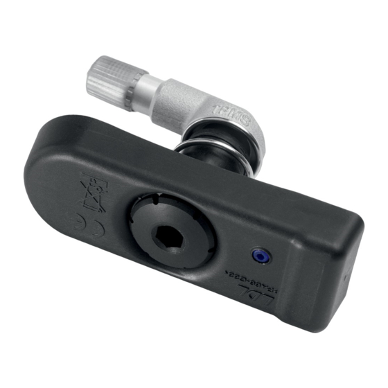
- Seite 2 ISTR 904 / 01 Avvertenza Warning Tenere il sensore pressione (3) nell’imballo. Non esporre il sensore Please keep pressure sensor (3) within packaging. Do not expose pressione (3) ad agenti atmosferici e polvere. Si consiglia di tene- pressure sensor (3) to the rain and dust at outside. It is ideal to re il trasmettitore in un ambiente asciutto con livello di umidità...
- Seite 3 ISTR 904 / 01 Attenzione Warning Terminata l'installazione del kit ed effettuata l'attivazione richiesta, Once the kit has been installed and the required activation has con il motoveicolo in funzione, il warning di gomme sgonfie si attiva been carried out, with the motorcycle in operation, the deflated al superamento della soglia del 25% rispetto al valore nominale tyre warning activates when the threshold is exceeded by 25% impostato tramite Setting menù.
- Seite 4 ISTR 904 / 01 Montaggio componenti kit Kit installation Importante Caution Verificare, prima del montaggio, che tutti i componenti risultino puliti e in Check that all components are clean and in perfect condition before in- perfetto stato. Adottare tutte le precauzioni necessarie per evitare di dan- stallation.
- Seite 5 ISTR 904 / 01 Selezionare il modello corretto di motoveicolo. Mediante il DDS Select the correct motorcycle model. Using DDS 2.0, access the 2.0, entrare nella sezione "Autodiagnosi Regolazioni" della cen- “Self-diagnosis Settings ” section of BBS control unit, as indi- tralina BBS", come indicato in figura (X3).
- Seite 6 ISTR 904 / 01...
- Seite 7 ISTR 904 / 01 Entrare nella sezione "Autodiagnosi Regolazioni" della centralina Access the “Self-diagnosis Settings” section of Hands Free control Hands Free (X5) ed eseguire la "Scrittura codice TPMS" (C2), come unit (X5) and perform “TPMS code writing” (C2), as indicated in the indicato nella figura (X6).
- Seite 8 ISTR 904 / 01 5 Nm ± 10% Montaggio sensore pressione pneumatici Fitting the tyre pressure sensor Attenzione Warning Montare sul cerchio ruota anteriore il sensore pressione attivato Fit the pressure sensor activated as “FRONT” on the front wheel come “FRONT” e montare sul cerchio ruota posteriore il sensore rim and fit the pressure sensor activated as “REAR”...
- Seite 9 ISTR 904 / 01 5 Nm ± 10% Attenzione Warning Avvitare la boccola speciale (4) sulla valvola (1) ad una velocità di Screw special bushing (4) on valve (1) at a maximum screwing speed avvitamento di massimo 2 giri al secondo. of 2 turns per second.
- Seite 10 ISTR 904 / 01 0° 0° 50° 270° 90° 270° 90° 180° 180° Montaggio pneumatico Mounting the tyre Applicare lubrificante specifico sul tallone inferiore (E1) e superiore Smear specific lubricant on the lower (E1) and upper (E2) beads of (E2) del pneumatico (E). Posizionare il cerchio ruota (D) sul mac- the tyre (E).
- Seite 11 ISTR 904 / 01 0° 50° 270° 90° 180° 20 mm Sostituzione pneumatico Changing the tyre In caso di sostituzione del pneumatico (E), orientare la ruota in When changing the tyre (E), aim the wheel so that valve (1) is in the modo che la valvola (1) risulti nella posizione mostrata in figura, o position shown in the figure with respect to machine vice (H).
- Seite 12 ISTR 904 / 01 0° 50° 270° 90° 180° Ruotare il cerchio (D), portando il sensore pressione (3) ad un an- Rotate rim (D) bringing pressure sensor (3) to an angle of 50° with golo di 50° rispetto al braccio tallonatore (F), come mostrato in respect to bead breaker arm (F), as shown in the figure (J2).
- Seite 13 ISTR 904 / 01 Note aggiuntive Additional notes Attenzione Warning Utilizzare solo il tappo della valvola originale. E’ assolutamente Use only the original valve cap. It is absolutely forbidden to use a vietato l’uso di un tappo realizzato in ottone. brass cap.
- Seite 14 ISTR 904 / 01 Note / Notes...
-
Seite 15: Avertissements Généraux
ISTR - 904 / 01 Kit sonde de pression de gonflage - 96680661A Kit Reifendrucksensor - 96680661A Symboles Symbole Pour faciliter la consultation de ce manuel, des symboles signalent Zum schnellen und übersichtlichen Lesen werden Symbole verwendet, des situations exigeant le maximum d'attention, des conseils pra- die außerordentlich wichtige Situationen, praktische Ratschläge oder tiques ou de simples informations. - Seite 16 ISTR 904 / 01 Attention Achtung Garder la sonde de pression (3) à l’intérieur de son emballage. Ne Bitte den Drucksensor (3) in der Verpackung lassen. Den Druck- pas exposer la sonde de pression (3) à la pluie et à la poussière à sensor (3) keinem Regen und Staub von außen aussetzen.
-
Seite 17: Ausbau Der Original-Bestandteile
ISTR 904 / 01 Attention Achtung Une fois l’installation du kit terminée et l’activation requise Nach erfolgter Installation des Kits und der geforderten effectuée, la moto étant en marche, l’avertissement de pneus Aktivierung wird bei laufendem Motorrad die Warnung vor platten dégonflés est activé... -
Seite 18: Montage Der Komponenten Des Kits
ISTR 904 / 01 Pose composants kit Montage der Komponenten des Kits Important Wichtig Vérifier, avant la pose, que tous les composants sont propres et en parfait Vor der Montage überprüfen, dass sich alle Komponenten im sauberen und per- état. Adopter toutes les précautions nécessaires pour éviter d'endomma- fekten Zustand befinden. - Seite 19 ISTR 904 / 01 Sélectionner le modèle correct du motocycle. À l’aide du DDS 2.0, Das richtige Motorrad-Modell wählen. Im DDS 2.0 den Abschnitt entrer dans la section « Autodiagnostic Réglages » du boîtier „Eigendiagnose Einstellungen” des BBS-Steuergeräts, wie in électronique BBS, comme la figure (X3) le montre.
- Seite 20 ISTR 904 / 01...
- Seite 21 ISTR 904 / 01 Entrer dans la section « Autodiagnostic Réglages » du boîtier élec- Den Abschnitt „Eigendiagnose Einstellungen” des Hands Free- tronique Hands Free (X5) et effectuer l’« Écriture code TPMS » Steuergeräts (X5) öffnen und die „Eingabe TPMS-Code” (C2) aus- (C2), comme la figure (X6) le montre.
- Seite 22 ISTR 904 / 01 5 Nm ± 10% Pose sonde de pression de gonflage Montage des Reifendrucksensors Attention Achtung Den als „FRONT“ aktivierten Drucksensor an der Vorderradfelge Poser sur la jante de roue avant la sonde de pression activée und den als „REAR“ aktivierten Drucksensor an der Hinterradfelge comme «...
- Seite 23 ISTR 904 / 01 5 Nm ± 10% Attention Achtung Serrer la bague spéciale (4) sur la valve (1) à une vitesse maximale Die Spezialbuchse (4) mit einer maximalen Einschraubgeschwin- de 2 tours par seconde. digkeit von 2 Umdrehungen pro Sekunde am Ventil (1) aufschrau- ben.
- Seite 24 ISTR 904 / 01 0° 0° 50° 270° 90° 270° 90° 180° 180° Pose pneu Reifenmontage Appliquer le lubrifiant spécifique sur le talon inférieur (E1) et supé- Spezielles Schmiermittel auf den unteren (E1) und oberen (E2) rieur (E2) du pneu (E). Positionner la jante de roue (D) sur l’outil- Wulst des Reifens (E) auftragen.
- Seite 25 ISTR 904 / 01 0° 50° 270° 90° 180° 20 mm Remplacement du pneu Reifenwechsel En cas de remplacement du pneu (E), orienter la roue de sorte que Bei einem Reifenwechsel (E) das Rad so ausrichten, dass sich das la soupape (1) soit dans la position affichée dans la figure, par rap- Ventil (1) in der in der Abbildung angegebenen Position auf Höhe port à...
- Seite 26 ISTR 904 / 01 0° 50° 270° 90° 180° Tourner la jante (D), en positionnant le capteur de pression (3) à Die Felge (D) drehen und den Drucksensor (3) in einem Winkel von un angle de 50° par rapport au bras talonneur (F), comme la figure 50°...
-
Seite 27: Zusätzliche Hinweise
ISTR 904 / 01 Notes supplémentaires Zusätzliche Hinweise Attention Achtung Utiliser uniquement le bouchon de la soupape d’origine. Il est ab- Nur die originale Ventilkappe verwenden. Die Verwendung einer solument interdit d’utiliser un bouchon fabriqué en laiton. Kappe aus Messing ist strengstens verboten. Attention Achtung En cas d’emploi d’un lubrifiant pour réparation pneu Fix-A-Flat,... - Seite 28 ISTR 904 / 01 Remarques Hinweis...
- Seite 29 ISTR - 904 / 01 Kit do sensor de pressão dos pneus - 96680661A Tyre pressure sensor kit - 96680661A Símbolos Symbols Para uma leitura rápida e racional, foram utilizados símbolos que To allow quick and easy consultation, this manual uses graphic evidenciam situações de máxima atenção, conselhos práticos ou symbols to highlight situations in which maximum care is required, simples informações.
- Seite 30 ISTR 904 / 01 Atenção Warning Mantenha o sensor de pressão (3) dentro da embalagem. Não ex- Please keep pressure sensor (3) within packaging. Do not expose ponha o sensor de pressão (3) à chuva e à poeira ao ar livre. É ideal pressure sensor (3) to the rain and dust at outside.
- Seite 31 ISTR 904 / 01 Atenção Warning Ao terminar a instalação do conjunto e ao realizar a ativação Once the kit has been installed and the required activation has solicitada, com a moto a funcionar, o aviso de pneus vazios é been carried out, with the motorcycle in operation, the deflated ativado ao superar o limiar de 25% em relação ao valor nominal tyre warning activates when the threshold is exceeded by 25%...
-
Seite 32: Montagem Dos Componentes
ISTR 904 / 01 Montagem dos componentes Kit installation Importante Caution Verifique, antes da montagem, se todos os componentes estão limpos e Check that all components are clean and in perfect condition before in- em perfeito estado. Adote todas as precauções necessárias para evitar da- stallation. - Seite 33 ISTR 904 / 01 Selecione o modelo correto do veículo motor. Com o DDS 2.0, en- Select the correct motorcycle model. Using DDS 2.0, access the tre na seção “Autodiagnóstico Regulações” da unidade de con- “Self-diagnosis Settings ” section of BBS control unit, as indi- trolo BBS, conforme indicado na figura (X3).
- Seite 34 ISTR 904 / 01...
- Seite 35 ISTR 904 / 01 Entre na seção “Autodiagnóstico Regulações” da unidade de con- Access the “Self-diagnosis Settings” section of Hands Free control trolo Hands Free (X5) e realize a “Escrita do código TPMS” (C2), unit (X5) and perform “TPMS code writing” (C2), as indicated in the conforme indicado na figura (X6).
- Seite 36 ISTR 904 / 01 5 Nm ± 10% Montagem do sensor de pressão dos pneus Fitting the tyre pressure sensor Atenção Warning Monte no jante da roda dianteira o sensor de pressão ativado como Fit the pressure sensor activated as “FRONT” on the front wheel “FRONT”...
- Seite 37 ISTR 904 / 01 5 Nm ± 10% Atenção Warning Aperte o casquilho especial (4) na válvula (1) a uma velocidade de Screw special bushing (4) on valve (1) at a maximum screwing speed aperto de no máximo 2 voltas por segundo. of 2 turns per second.
- Seite 38 ISTR 904 / 01 0° 0° 50° 270° 90° 270° 90° 180° 180° Montagem do pneu Mounting the tyre Aplique lubrificante específico no talão inferior (E1) e superior (E2) Smear specific lubricant on the lower (E1) and upper (E2) beads of do pneu (E).
- Seite 39 ISTR 904 / 01 0° 50° 270° 90° 180° 20 mm Substituição do pneu Changing the tyre Em caso de substituição do pneu (E), oriente a roda de modo que When changing the tyre (E), aim the wheel so that valve (1) is in the a válvula (1) esteja na posição mostrada na figura em relação ao position shown in the figure with respect to machine vice (H).
- Seite 40 ISTR 904 / 01 0° 50° 270° 90° 180° Gire a jante (D), colocando o sensor de pressão (3) a um ângulo de Rotate rim (D) bringing pressure sensor (3) to an angle of 50° with 50° com respeito ao braço talonador (F), conforme mostrado na respect to bead breaker arm (F), as shown in the figure (J2).
- Seite 41 ISTR 904 / 01 Notas adicionais Additional notes Atenção Warning Utilize somente a tampa da válvula original. É absolutamente proi- Use only the original valve cap. It is absolutely forbidden to use a bido o uso de uma tampa feita de latão. brass cap.
- Seite 42 ISTR 904 / 01 Notas / Notes...
-
Seite 43: Advertencias Generales
ISTR - 904 / 01 Kit sensor presión neumáticos - 96680661A タイヤ空気圧センサーキット - 96680661A Símbolos シンボル Para una lectura rápida y racional se han empleado símbolos que 素早くかつ合理的に読み進めることができるように、本マニュア evidencian situaciones de máxima atención, consejos prácticos o ルではいくつかのシンボルを導入し、最大限の注意を払う必要 simples informaciones. Prestar mucha atención al significado de がある状況や、推奨事項、または一般情報を明確にしてありま... - Seite 44 ISTR 904 / 01 Advertencia 警告 Mantener el sensor de presión (3) dentro del embalaje. No exponer 圧力センサー は梱包内に保管してください。圧力センサー el sensor de presión (3) a condiciones externas de lluvia y polvo. Se を屋外の雨やホコリにさらさないでください。トランスミッ recomienda mantener el transmisor en ambiente seco con hume- ターは気温...
- Seite 45 ISTR 904 / 01 Atención 警告 Después de finalizar la instalación del kit y efectuar la activación キットの取り付けが完了し、車両が稼働している状態でアクティ solicitada, con la moto en marcha, la advertencia de neumáticos ベーションを実行したら、設定メニューで設定した公称値に対し desinflados se activa al superar el umbral del 25% con respecto al て...
- Seite 46 ISTR 904 / 01 Montaje componentes kit キット部品の取り付け Importante 重要 Controlar, antes del montaje, que todos los componentes se encuentren 取り付け前にすべての部品に汚れがなく、完璧な状態であることを確 limpios y en perfecto estado. Adoptar todas las precauciones necesarias 認します。 作業する部品の外側表面を傷つけないために、必要な予 para evitar daños en la superficie exterior de los componentes donde se 防措置を取ってください。...
- Seite 47 ISTR 904 / 01 Seleccionar el modelo correcto de motocicleta. Mediante el DDS 正しい車両モデルを選択します。DDS 2.0 から、BBS コントロ 2.0, entrar en la sección «Autodiagnosis Regulaciones» de la ールユニットの「自己診断 調整」セクションに入ります (図 central BBS, come se indica en la figura (X3). Seleccionar la opción (X3) 参照)。図...
- Seite 48 ISTR 904 / 01...
- Seite 49 ISTR 904 / 01 Entrar en la sección «Autodiagnosis Regulaciones» de la central Hands Free コントロールユニットの「自己診断 調整」セクショ Hands Free (X5) y efectuar la «Escritura código TPMS» (C2) como ン (X5) に入り、図 (X6) に示すように「TPMS コードの書き込 se indica en la figura (X6); み」(C2) を実行します。...
- Seite 50 ISTR 904 / 01 5 Nm ± 10% Montaje sensor presión neumáticos タイヤ空気圧センサーの取り付け Atención 警告 Montar el sensor de presión activado como “FRONT” en la llanta 「FRONT」として起動させた圧力センサーをフロントホイール delantera y montar el sensor de presión activado como “REAR” en に、「REAR」として起動させた圧力センサーをリアホイールに取 la llanta trasera. り付けてください。...
- Seite 51 ISTR 904 / 01 5 Nm ± 10% Atención 警告 Atornillar el casquillo especial (4) en la válvula (1) a una velocidad 最大毎秒 2 回転の締め付け速度で、専用ブッシュ (4) をバルブ máxima de atornillado de 2 vueltas por segundo. (1) にねじ込んでください。 Atención 警告 Dar al menos 5 vueltas al casquillo especial (4) en la válvula (1). 専用ブッシュ...
- Seite 52 ISTR 904 / 01 0° 0° 50° 270° 90° 270° 90° 180° 180° Montaje neumático タイヤの取り付け Aplicare lubricante específico en el talón inferior (E1) y superior (E2) タイヤ (E) の下側ビード (E1) と上側ビード (E2) に規定の潤 del neumático (E). Posicionar la llanta (D) en la maquinaria, y girar- 滑油を塗布します。ホイールリム...
- Seite 53 ISTR 904 / 01 0° 50° 270° 90° 180° 20 mm Sustitución neumático タイヤの交換 En caso de sustitución del neumático (E), orientar la rueda para タイヤ (E) を交換する場合は、バルブ (1) が機械のバイス (H) que la válvula (1) resulte en la posición ilustrada en la figura, con に対して図に示す位置にくるようにホイールを合わせます。図中...
- Seite 54 ISTR 904 / 01 0° 50° 270° 90° 180° Girar la llanta (D), posicionando el sensor de presión (3) a un ángulo ホイールリム (D) を回転させ、図 (J2) に示すように圧力センサ de 50° con respecto al brazo talonador (F), como ilustra la figura ー (3) をビードブレーカーアーム (F) に対して 50 度の位置に (J2).
- Seite 55 ISTR 904 / 01 Notas adicionales 追記 警告 Atención オリジナルのバルブキャップのみを使用してください。真鍮製の Utilizar solo el tapón de la válvula original. Está estrictamente pro- キャップの使用は堅く禁じられています。 hibido el uso de tapones de latón. 警告 Advertencia パンク修理用潤滑油を使用した場合は、圧力センサーを交換して Si se usa lubricante como sellador de neumáticos, sustituir el sen- ください。...
- Seite 56 ISTR 904 / 01 Notas / 参考...
- Seite 57 レース専用部品 ご注文書 ご注文商品 商品名 P/N 商品名 P/N 商品名 P/N 商品名 P/N 商品名 P/N お客様ご記入欄 私は上記レース専用部品を下記車両に装着し、サーキット走行のみに 利用し、一般公道には利用しません。 車台番号 ZDM モデル名 お客様署名 ご注文日 ドゥカティ正規ネットワーク店記入欄 お客様に上記レース専用部品を販売し、レース専用部品のご利用方法を 説明いたしました。 販売店署名 販売日 年 月 日 販売店様へお願い 1. 上記ご記入の上、弊社アフターセールス 部までFAX してください 。FAX : 03 - 6692 - 1317 1. 上記ご記入の上、弊社アフターセールス 部までFAX してください 。FAX : 03 - 6692 - 1317 2.