Ducati PERFORMANCE 96680503A Montageanleitung
Inhaltsverzeichnis
ISTR - 687 / 03
Kit antifurto - 96680503A
Anti-theft system kit - 96680503A
Simbologia
Per una lettura rapida e razionale sono stati impiegati simboli che
evidenziano situazioni di massima attenzione, consigli pratici o
semplici informazioni. Prestare molta attenzione al significato dei
simboli, in quanto la loro funzione è quella di non dovere ripete-
re concetti tecnici o avvertenze di sicurezza. Sono da considerare,
quindi, dei veri e propri "promemoria". Consultare questa pagina
ogni volta che sorgeranno dubbi sul loro significato.
Attenzione
La non osservanza delle istruzioni riportate può creare una situa-
zione di pericolo e causare gravi lesioni personali e anche la morte.
Importante
Indica la possibilità di arrecare danno al veicolo e/o ai suoi compo-
nenti se le istruzioni riportate non vengono eseguite.
Note
Fornisce utili informazioni sull'operazione in corso.
Riferimenti
I particolari evidenziati in grigio e riferimento numerico (Es.
rappresentano l'accessorio da installare e gli eventuali componenti
di montaggio forniti a kit.
I particolari con riferimento alfabetico (Es.
componenti originali presenti sul motoveicolo.
Tutte le indicazioni destro o sinistro si riferiscono al senso di marcia
del motociclo.
Avvertenze generali
Attenzione
Le operazioni riportate nelle pagine seguenti devono essere ese-
guite da un tecnico specializzato o da un'officina autorizzata Du-
cati.
Attenzione
Le operazioni riportate nelle pagine seguenti se non eseguite a re-
gola d'arte possono pregiudicare la sicurezza del pilota.
Note
Documentazione necessaria per eseguire il montaggio del Kit è il
Manuale Officina, relativo al modello di moto in vostro possesso.
Note
Nel caso fosse necessaria la sostituzione di un componente del kit
consultare la tavola ricambi allegata.
1
Symbols
The symbols used in this manual are aimed at making reading di-
rect and easy. The symbols are used either to draw the reader's
attention on potentially hazardous conditions, or to give practical
advice or to supply general information. Pay the utmost attention
to these symbols as they are used to remind of technical principles
or safety measures which will not be repeated extensively. They
must therefore be considered as "reminders". Check with this page
in case of doubt about their meaning.
Failure to comply with these instructions may put you at risk and
lead to severe injury or death.
It indicates the possibility of damaging the motorcycle and/or its
components if the instructions are not followed.
It supplies useful information about the operation in progress.
References
The parts highlighted in grey and with a reference number (e.g.
1
)
represent the accessory to be installed and any assembly components
supplied with the kit.
The parts with alphabetic reference (e.g.
A
) rappresentano i
components present on the motorcycle.
All left and right indications are referred to the motorcycle direc-
tion of travel (forward riding position).
General notes
The operations listed in the following pages must be carried out by
a specialised technician or by a Ducati authorised service centre.
Carefully perform the operations on the following pages since they
might negatively affect rider safety.
The Workshop Manual of your motorcycle model is the documen-
tation required to assemble the Kit.
Should it be necessary to change any kit parts, please refer to the
attached spare part table.
Operating, servicing and maintaining a passenger vehicle or off-
highway motor vehicle can expose you to chemicals including en-
gine exhaust, carbon monoxide, phthalates, and lead, which are
known to the State of California to cause cancer and birth defects
or other reproductive harm. To minimize exposure, avoid breath-
ing exhaust, do not idle the engine except as necessary, service
your vehicle in a well-ventilated area and wear gloves or wash your
hands frequently when servicing your vehicle. For more informa-
tion go to www.P65Warnings.ca.gov/passenger-vehicle.
Warning
Important
Notes
Warning
Warning
Notes
Notes
Warning
1
)
A
) represent the original
Inhaltsverzeichnis

Verwandte Anleitungen für Ducati PERFORMANCE 96680503A


Inhaltszusammenfassung für Ducati PERFORMANCE 96680503A
- Seite 1 The operations listed in the following pages must be carried out by Attenzione a specialised technician or by a Ducati authorised service centre. Le operazioni riportate nelle pagine seguenti devono essere ese- guite da un tecnico specializzato o da un’officina autorizzata Du- Warning cati.
- Seite 2 ISTR 687 / 03 Importante Important I componenti del kit possono essere soggetti ad aggiornamenti; The parts of the kit can be updated; for information always up to consultare il DCS (Dealer Communication System) per avere infor- date, please refer to DCS (Dealer Communication System). mazioni sempre aggiornate.
- Seite 3 ISTR 687 / 03 OPEN Smontaggio componenti originali Removing the original components Smontaggio sella passeggero e sella pilota Rider seat and passenger seat disassembly Inserire la chiave (A) nella serratura sella e ruotarla in senso ora- Insert the key (A) into the seat lock and turn it clockwise until the rio fino a sentire lo scatto del gancio, come indicato in figura (X1).
- Seite 4 ISTR 687 / 03...
- Seite 5 ISTR 687 / 03 Smontaggio gruppo portatarga Removing the number plate holder unit Svitare le n.4 viti superiori (B2) con rondelle (B3). Svitare le n.2 viti Loosen no.4 upper screws (B2) with washers (B3). Loosen no.2 low- inferiori (B4) con boccole (B5). Recuperare le n.4 rondelle (B3), le er screws (B4) with bushings (B5).
- Seite 6 ISTR 687 / 03 Rimuovere il tappo (D) dal connettore (E) del ramo cablaggio anti- Remove cap (D) from anti-theft system wiring branch connector furto. Sfilare i n.3 relè (F) dalle alette (G) della staffa supporto relè. (E). Slide no.3 relays (F) off tabs (G) of relay support bracket.
- Seite 7 ISTR 687 / 03 Montaggio componenti kit Kit installation Importante Caution Verificare, prima del montaggio, che tutti i componenti risultino Check that all components are clean and in perfect condition be- puliti e in perfetto stato. Adottare tutte le precauzioni necessarie fore installation.
- Seite 8 ISTR 687 / 03 Premontaggio prolunga connessione antifurto Pre-fitting the anti-theft system connection exten- sion Attenzione Warning È assolutamente fatto divieto montare il cablaggio antifurto senza installare anche la centralina antifurto. La mancanza di collega- It is absolutely forbidden to assemble anti-theft system wiring mento alla centralina comporterebbe la NON corretta funzionalità...
- Seite 9 ISTR 687 / 03 Montaggio centralina Fitting the control unit Inserire la centralina (4) nell’apposita sede all’interno del rivesti- Fit control unit (4) in the suitable seat inside compartment lining mento vasca (1). Collegare la prolunga (6) al connettore (4A) della (1).
- Seite 10 ISTR 687 / 03 6 Nm ± 10% 6 Nm ± 10% 6 Nm ± 10% 6 Nm ± 10%...
- Seite 11 ISTR 687 / 03 Rimontaggio gruppo portatarga Refitting the number plate holder unit Posizionare il gruppo portatarga (B) sotto al maniglione (H) e im- Place number plate holder unit (B) under grab handle (H) and start puntare le n.4 viti (5). Nella parte inferiore del gruppo portatarga no.4 screws (5).
- Seite 12 ISTR 687 / 03 Rimontaggio sella pilota Rider seat reassembly Posizionare la parte anteriore della sella pilota (A), provvista di aso- Position the front side of rider seat (A), provided with slots (A6), le (A6), nelle guide (A3) ed inserire il perno (A4) nella sede (A5). Pre- into guides (A3) and insert pin (A4) into its seat (A5).
- Seite 13 ISTR 687 / 03 Rimontaggio sella passeggero Passenger seat reassembly Lubrificare la sede (T1) del perno (A7) con SHELL RETINAX HD2. Lubricate the seat (T1) of the pin (A7) with SHELL RETINAX HD2. Posizionare la sella passeggero (A1) e inserire la linguetta (A8) Position passenger seat (A1) and insert the tab (A8) into the hous- nell’alloggio (T2) presente all’interno della vasca portaoggetti.
-
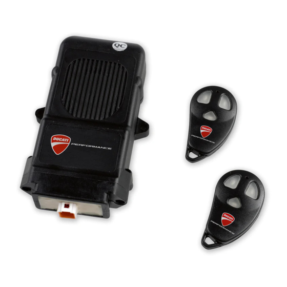
Seite 14: Remote Controls
ISTR 687 / 03 Telecomandi Remote controls Importante Caution In dotazione al kit antifurto vengono forniti n.2 telecomandi (3); la Within the antitheft system kit you are provided with no. 2 re- capacità massima di gestione del sistema antifurto è n.8 teleco- mote controls (3). - Seite 15 ISTR 687 / 03 Condizione partendo dal sistema di allarme NON Condition with DISABLED alarm system inserito With disabled system, (parked motorcycle with disabled alarm) af- A sistema disinserito, (moto parcheggiata senza allarme attivato) ter 36 hours the system switches to Stand-by mode. It is no longer trascorso il periodo di 36 ore il sistema entra in modalità...
- Seite 16 ISTR 687 / 03 Siren alarm disabling Esclusione sirena During the first 5 seconds after enabling the system (dashboard Durante i primi 5 secondi d'inserimento (led sul cruscotto acceso LED steady on) it is possible to disable the siren by pressing but- fisso) premendo il tasto (3B) del telecomando è...
- Seite 17 ISTR 687 / 03 Attenzione Warning Nel caso venga acceso il quadro del veicolo (key-on) o venga pre- When vehicle instrument panel is switched on (key-on) or if but- muto il tasto (3B) del telecomando (allarme panico), il suono della ton (3B) on remote control is pressed (panic alarm), the siren is sirena viene ripristinato.
- Seite 18 ISTR 687 / 03 Memorizzazione nuovi telecomandi Storing new remote controls Importante Caution In caso di problematiche nella realizzazione della seguente proce- In case of problems in implementing the following procedure, dura prego contattare i seguenti numeri telefonici: please call the phone numbers below: - ITALIA: +39 366 4966876;...
- Seite 19 ISTR 687 / 03 Questa operazione permette di personalizzare il codice segreto di This procedure allows you to customise the secret override code sblocco da quello di fabbrica (1-2-3) a quello desiderato, seguendo and pass from the factory-set one (1-2-3) to your own; proceed as questa procedura: follows: - Da cruscotto comporre il codice segreto come descritto nel para-...
- Seite 20 ISTR 687 / 03 Note / Notes...
- Seite 21 Ducati. Die auf den folgenden Seiten beschriebenen Arbeitsmaßnahmen müssen von einem Fachtechniker oder einer Ducati Vertragswerk- Attention statt ausgeführt werden. Les opérations indiquées dans les pages suivantes, au cas où elles Achtung ne seraient pas effectuées selon les règles de l'art pourraient com-...
- Seite 22 ISTR 687 / 03 Important Wichtig Les composants du kit peuvent être soumis à des mises à jour ; Die Bestandteile des Kits können Aktualisierungen unterliegen. veuillez consulter le DCS (Dealer Communication System) pour des Lesen Sie stets die Angaben im DCS (Dealer Communication Sys- informations toujours actualisées.
-
Seite 23: Ausbau Der Original-Bestandteile
ISTR 687 / 03 OPEN Dépose composants d'origine Ausbau der Original-Bestandteile Dépose selle passager et selle pilote Abnahme von Beifahrer- und Fahrersitzbank Insérer la clé (A) dans la serrure de la selle et la tourner dans le sens Den Schlüssel (A) in das Sitzbankschloss einstecken und so lange des aiguilles d'une montre jusqu'à... - Seite 24 ISTR 687 / 03...
- Seite 25 ISTR 687 / 03 Dépose de l'ensemble support de plaque d'immatri- Abnahme der Kennzeichenhaltereinheit culation Die 4 oberen Schrauben (B2) mit Unterlegscheiben (B3) lösen. Die Desserrer les 4 vis supérieures (B2) avec rondelles (B3). Desserrer 2 unteren Schrauben (B4) mit Buchsen (B5) lösen. Die 4 Unter- les 2 vis inférieures (B4) avec bagues (B5).
- Seite 26 ISTR 687 / 03 Retirer le bouchon (D) du connecteur (E) du brin câblage antivol. Die Verschlusskappe (D) vom Verbinder (E) des Zweigs der Dieb- Sortir les 3 relais (F) des pattes (G) de la bride de support relais. stahlsicherungsverkabelung entfernen. Die 3 Relais (F) von den Rippen (G) des Relais-Stützbügels abziehen.
-
Seite 27: Montage Der Komponenten Des Kits
ISTR 687 / 03 Pose composants kit Montage der Komponenten des Kits Important Wichtig Vérifier, avant la pose, que tous les composants sont propres et en Vor der Montage überprüfen, dass sich alle Komponenten im sau- parfait état. Adopter toutes les précautions nécessaires pour éviter beren und perfekten Zustand befinden. - Seite 28 ISTR 687 / 03 Pré-installation de la rallonge connexion antivol Vormontage der Verlängerung der Diebstahlsiche- rungsverbindung Attention Achtung Il est absolument interdit de poser le câblage antivol avant l'ins- tallation du boîtier électronique antivol. S'il n'y a pas de connexion Es ist strikt verboten, die Verkabelung der Diebstahlsicherung zu au boîtier électronique, les dispositifs d'éclairage du véhicule NE montieren, ohne gleichzeitig auch das Diebstahlsicherungssteu-...
- Seite 29 ISTR 687 / 03 Installation du boîtier électronique Montage des Steuergeräts Introduire le boîtier électronique (4) dans son logement à l'inté- Das Steuergerät (4) in die entsprechende Aufnahme in der Wan- rieur du revêtement bac vide-poches.(1). Relier la rallonge (6) au nenverkleidung (1) einfügen.
- Seite 30 ISTR 687 / 03 6 Nm ± 10% 6 Nm ± 10% Relier la prise (4A) du phare supplémentaire gauche à la rallonge Den Anschluss (4A) des linken Zusatzscheinwerfers an die Verlän- (9). gerung (9) schließen. Disposer le câblage du phare supplémentaire gauche sur le moto- Die Verkabelung des linken Zusatzscheinwerfers gemäß...
- Seite 31 ISTR 687 / 03 Repose de l'ensemble support de plaque d'immatri- Montage der Kennzeichenhaltereinheit culation Die Kennzeichenhaltereinheit (B) unter dem Haltegriff (H) an- Positionner l'ensemble support de plaque d'immatriculation (B) ordnen und die 4 Schrauben (5) ansetzen. Die 2 unteren Original- au-dessous de la poignée passager (H) et présenter les 4 vis (5).
- Seite 32 ISTR 687 / 03 Repose de la selle pilote Montage der Fahrersitzbank Positionner la partie avant de la selle pilote (A), dotée de crans Den vorderen Teil der Fahrersitzbank (A), der mit Langlöchern (A6) (A6), dans les guides (A3) et insérer le pivot (A4) dans le logement versehen ist, in den Führungen (A3) anordnen und den Bolzen (A4) (A5).
- Seite 33 ISTR 687 / 03 Repose selle passager Montage der Beifahrersitzbank Lubrifier le logement (T1) du pivot (A7) avec SHELL RETINAX HD2. Den Sitz (T1) des Bolzen (A7) mit SHELL RETINAX HD2 schmie- Positionner la selle passager (A1) et insérer la languette (A8) dans ren.
- Seite 34 ISTR 687 / 03 Télécommandes Fernbedienungen Important Wichtig Le kit antivol est fourni avec n. 2 télécommandes (3) ; la capaci- Im Lieferumfang des Kits der Diebstahlsicherung sind 2 Fern- té maximale de gestion du système antivol est de n. 8 télécom- bedienungen (3) enthalten.
- Seite 35 ISTR 687 / 03 État depuis le système d'alarme DÉSACTIVÉ Von einem NICHT eingeschaltetem Alarmsystem ausgehende Bedingung Le système désactivé (moto garée sans alarme active), après 36 heures le système entre en mode Stand-by. Il n'est plus possible Bei ausgeschaltetem System (abgeparktes Motorrad ohne aktivier- d'insérer l'alarme car le récepteur est désactivé...
- Seite 36 ISTR 687 / 03 Désactivation de la sirène Ausschluss der Alarmsirene Pendant les 5 premières secondes d'activation, (led sur le tableau Während der ersten 5 Sekunden nach dem Einschalten (LED im de bord allumée fixe), il est possible de désactiver le fonctionne- Cockpit leuchtet permanent) kann durch Drücken der Taste (3B) ment de la sirène en appuyant sur la touche (3B) de la télécom- der Fernbedienung die Funktion der Sirene ausgeschlossen wer-...
- Seite 37 ISTR 687 / 03 Attention Achtung Au cas où le tableau de bord du véhicule serait allumé (key - on) ou Sollte das Cockpit des Fahrzeugs eingeschaltet (key-on) oder die la touche (3B) de la télécommande (alarme panique) serait enfon- Taste (3B) der Fernbedienung gedrückt werden (Panik-Alarm), wird cée, le son de la sirène est rétabli.
- Seite 38 ISTR 687 / 03 Mémorisation des télécommandes nouvelles. Speichern neuer Fernbedienungen Important Wichtig En cas de problèmes pendant l'exécution de la procédure suivante Im Falle von Problemen bei der Durchführung folgenden Vorgangs veuillez appeler les numéros de téléphone indiqués ci-après : bitten wir Sie, uns unter den nachstehenden Telefonnummern zu - ITALIE : +39 366 4966876 ;...
-
Seite 39: Instandhaltung Des Alarmsystems
ISTR 687 / 03 Il est possible de personnaliser le code confidentiel de déblocage, Dieses Verfahren ermöglicht anhand des nachstehenden Verfah- en modifiant le code d'usine (1-2-3) selon la procédure cidessous: rens die Eingabe eines persönlichen bzw. anderen als den werksin- - Depuis le tableau de bord taper le code confidentiel, comme dé- tern eingegebenen Freigabecode (1-2-3): crit au paragraphe précédent. - Seite 40 ISTR 687 / 03 Remarques Hinweis...
-
Seite 41: Advertências Gerais
Advertências gerais Warning The operations listed in the following pages must be carried out by a specialised technician or by a Ducati authorised service centre. Atenção As operações mostradas nas páginas a seguir devem ser execu- Warning tadas por um técnico especializado ou por uma oficina autorizada... - Seite 42 ISTR 687 / 03 Important Importante The parts of the kit can be updated; for information always up to Os componentes do conjunto podem sofrer atualizações; consulte date, please refer to DCS (Dealer Communication System). o DCS (Dealer Communication System) a fim de obter informações sempre atualizadas.
- Seite 43 ISTR 687 / 03 OPEN Desmontagem dos componentes originais Removing the original components Desmontagem o assento do passageiro e o assento Rider seat and passenger seat disassembly do condutor Insert the key (A) into the seat lock and turn it clockwise until the Insira a chave (A) na fechadura do assento e rode-a no sentido ho- seat catch disengages with an audible click, as shown in the figure rário até...
- Seite 44 ISTR 687 / 03...
- Seite 45 ISTR 687 / 03 Desmontagem do grupo porta-matrícula Removing the number plate holder unit Desatarraxe os 4 parafusos superiores (B2) com as anilhas (B3). Loosen no.4 upper screws (B2) with washers (B3). Loosen no.2 low- Desatarraxe os 2 parafusos inferiores (B4) com os casquilhos (B5). er screws (B4) with bushings (B5).
- Seite 46 ISTR 687 / 03 Remova a tampa (D) do conector (E) da ramificação da cablagem Remove cap (D) from anti-theft system wiring branch connector do dispositivo antirroubo. Retire os 3 relés (F) das aletas (G) do (E). Slide no.3 relays (F) off tabs (G) of relay support bracket. grampo de suporte dos relés.
-
Seite 47: Montagem Dos Componentes
ISTR 687 / 03 Montagem dos componentes Kit installation Importante Caution Verifique, antes da montagem, se todos os componentes estão Check that all components are clean and in perfect condition be- limpos e em perfeito estado. Adote todas as precauções necessá- fore installation. - Seite 48 ISTR 687 / 03 Pré-montagem da extensão da conexão do disposi- Pre-fitting the anti-theft system connection exten- tivo antirroubo sion Atenção Warning É absolutamente proibido montar a cablagem anti-roubo sem ins- It is absolutely forbidden to assemble anti-theft system wiring talar também a unidade eletrónica anti-roubo.
- Seite 49 ISTR 687 / 03 Montagem da unidade eletrónica Fitting the control unit Insira a unidade eletrónica (4) na específica sede dentro do revesti- Fit control unit (4) in the suitable seat inside compartment lining mento do compartimento (1). Ligue a extensão (6) ao conector (4A) (1).
- Seite 50 ISTR 687 / 03 6 Nm ± 10% 6 Nm ± 10% Conecte a tomada (4A) do farol esquerdo ao prolongamento (9). Disponha a cablagem do farol esquerdo na motocicleta como mos- trado na figura, tendo o cuidado de fixá-la com as braçadeiras de serrilha pequenas (10) e a braçadeira de botão (11).
- Seite 51 ISTR 687 / 03 Remontagem do grupo porta-matrícula Refitting the number plate holder unit Posicione o grupo porta-matrícula (B) debaixo da pega (H) e encos- Place number plate holder unit (B) under grab handle (H) and start te os 4 parafusos (5). Na parte inferior do grupo porta-matrícula, no.4 screws (5).
- Seite 52 ISTR 687 / 03 Remontagem do assento do piloto Rider seat reassembly Coloque a parte dianteira do assento do piloto (A), equipado com Position the front side of rider seat (A), provided with slots (A6), olhais (A6), nas guias (A3) e introduza o pino (A4) na sede (A5). into guides (A3) and insert pin (A4) into its seat (A5).
- Seite 53 ISTR 687 / 03 Remontagem do assento do passageiro Passenger seat reassembly Lubrifique a sede (T1) do pino (A7) com SHELL RETINAX HD2. Co- Lubricate the seat (T1) of the pin (A7) with SHELL RETINAX HD2. loque o assento do passageiro (A1) e introduza a lingueta (A8) no Position passenger seat (A1) and insert the tab (A8) into the hous- alojamento (T2) presente no interior do compartimento porta-ob- ing (T2) present inside the glove compartment.
-
Seite 54: Remote Controls
ISTR 687 / 03 Telecomandos Remote controls Importante Caution Junto com o kit anti-roubo, são fornecidos n.2 telecomandos (3); Within the antitheft system kit you are provided with no. 2 re- A capacidade máxima de gestão do sistema anti-roubo é de 8 te- mote controls (3). - Seite 55 ISTR 687 / 03 Condição partindo do sistema de alarme NÃO ativa- Condition with DISABLED alarm system With disabled system, (parked motorcycle with disabled alarm) af- Com o sistema desativado, (moto estacionada sem alarme ativa- ter 36 hours the system switches to Stand-by mode. It is no longer do) transcorrido o período de 36 horas, o sistema entra no modo possible to enable the alarm since the receiver is disabled and no de Stand-by.
- Seite 56 ISTR 687 / 03 Desativação da sirene Siren alarm disabling Durante os primeiros 5 segundos da ativação (led no painel de ins- During the first 5 seconds after enabling the system (dashboard trumentos aceso fixo), pressionando a tecla (3B) do telecomando, LED steady on) it is possible to disable the siren by pressing but- é...
- Seite 57 ISTR 687 / 03 Atenção Warning Caso o quadro do veículo seja acendido (key-on) ou seja pressiona- When vehicle instrument panel is switched on (key-on) or if but- da a tecla (3B) do telecomando (alarme de pânico), o som da sirene ton (3B) on remote control is pressed (panic alarm), the siren is é...
- Seite 58 ISTR 687 / 03 Memorização dos novos telecomandos Storing new remote controls Importante Caution No caso de problemas na realização do procedimento a seguir, por In case of problems in implementing the following procedure, favor, contate os seguintes números telefónicos: please call the phone numbers below: - ITÁLIA: +39 366 4966876;...
- Seite 59 ISTR 687 / 03 Esta operação permite personalizar o código secreto de desblo- This procedure allows you to customise the secret override code queio daquele de fábrica (1-2-3) para aquele desejado, seguindo and pass from the factory-set one (1-2-3) to your own; proceed as este procedimento: follows: - Através do painel de instrumentos, componha o código secreto...
- Seite 60 ISTR 687 / 03 Notas / Notes...
-
Seite 61: Advertencias Generales
警告 以下のページに記載されている作業は、専門の技術者、またはド ゥカティ正規サービスセンターが実施しなければなりません。 Atención Las operaciones indicadas en las páginas siguientes debe realizar- 警告 las un técnico especializado o un taller autorizado Ducati. 以下のページに記載されている作業が規定通りに実施されない と、ライダーの安全性を脅かすおそれがあります。 Atención Las operaciones descritas en las siguientes páginas deben realizar- 参考 se correctamente para no perjudicar la seguridad del piloto. - Seite 62 ISTR 687 / 03 Importante 重要 Es posible que los componentes del kit sean actualizados; consul- キットの構成部品は更新されることがあります。DCS (Dealer tar el DCS (Dealer Communication System) para tener información Communication System) から常に最新の情報をチェックするよ siempre al día. うにしてください。 Pos. Denominación 名称 Revestimiento compartimiento 小物入れカバー Junta ラバー...
- Seite 63 ISTR 687 / 03 OPEN Desmontaje componentes originales オリジナル部品の取り外し Desmontaje asiento pasajero y asiento piloto パッセンジャーシートおよびライダーシートの取り外し Introducir la llave (A) en la cerradura y girarla en el sentido de las シートロックにキー (A) を差し込み、図 (X1) のようにカチっ agujas del reloj hasta oír el chasquido del gancho, como indica la と音がするまで時計方向に回します。...
- Seite 64 ISTR 687 / 03...
- Seite 65 ISTR 687 / 03 Desmontaje grupo porta-matrícula ナンバープレートホルダーユニットの取り外し Desatornillar los 4 tornillos superiores (B2) con arandelas (B3). 4本の上側スクリュー (B2) をワッシャー (B3) と一緒に緩めて外 Desatornillar los 2 tornillos inferiores (B4) con casquillos (B5). Re- します。 2 本の下側スクリュー (B4) をブッシュ (B5) と一緒に cuperar las 4 arandelas (B3), los 2 tornillos inferiores (B4) y los 2 緩めて外します。...
- Seite 66 ISTR 687 / 03 Quitar el tapón (D) del conector (E) del tramo cableado antirrobo. 盗難防止分岐配線のコネクター (E) からキャップ (D) を取り外 Extraer los 3 relés (F) de las aletas (G) del sostén soporte relés. します。 リレーマウントブラケットのタブ (G) から 3 つのリレ ー (F) を抜き取ります。...
- Seite 67 ISTR 687 / 03 Montaje componentes kit キット部品の取り付け Importante 重要 Controlar, antes del montaje, que todos los componentes se en- 取り付け前にすべての部品に汚れがなく、完璧な状態であること cuentren limpios y en perfecto estado. Adoptar todas las precau- を確認します。作業する部品の外側表面を傷つけないために、必 ciones necesarias para evitar daños en la superficie exterior de los 要な予防措置を取ってください...
- Seite 68 ISTR 687 / 03 Premontaje prolongación conexión antirrobo 盗難防止装置接続延長ケーブルの仮取り付け Atención 警告 Está absolutamente prohibido montar el cableado antirrobo sin 防犯コントロールユニットを設置せ ずに防犯ケーブルを取り付け instalar la central antirrobo. La falta de conexión a la central causa- ることは禁止 されています。コントロールユニットに接 続され ría un funcionamiento INCORRECTO de las señales luminosas del ていないと、車両の光信号が正しく...
- Seite 69 ISTR 687 / 03 Montaje central コントロールユニットの取り付け Introducir la central (4) en el específico alojamiento dentro del re- コントロールユニット (4) を小物入れカバー (1) の内側の所定の vestimiento compartimiento (1). Conectar la prolongación (6) al co- 位置に挿入します。 延長ケーブル (6) をコントロールユニット nector (4A) de la central (4). Posicionar el grupo central dentro del (4) のコネクター...
- Seite 70 ISTR 687 / 03 6 Nm ± 10% 6 Nm ± 10% Conectar la toma (4A) del faro izquierdo a la prolongación (9). 左ランプのソケット (4A) をエクステンション (9) に接続しま Colocar el cableado del faro izquierdo en la moto como ilustra la す。...
- Seite 71 ISTR 687 / 03 Montaje grupo porta-matrícula ナンバープレートホルダーユニットの取り付け Posicionar el grupo porta-matricula (5) debajo del asa (H) e intro- ナンバープレートホルダーユニット (B) をハンドルレール (H) ducir los 4 tornillos (5). En la parte inferior del grupo porta-matri- の下に配置し、4 本のスクリュー (5) を差し込みます。 ナンバ cula, introducir los 2 tornillos inferiores originales (B4) con relativos ープレートホルダーユニットの下側から...
- Seite 72 ISTR 687 / 03 Montaje asiento piloto ライダーシートの取り付け Posicionar la parte delantera del asiento piloto (A), que tiene ojales ライダーシート (A) の溝 (A6) が設けられている前部をガイド (A6) en las guías (A3) e introducir el perno (A4) en el alojamiento (A3) に配置し、ピン (A4) を所定の位置 (A5) に差し込みます。 (A5).
- Seite 73 ISTR 687 / 03 Montaje asiento pasajero パッセンジャーシートの取り付け Lubricar el alojamiento (T1) del perno (A7) con SHELL RETINAX ピン (A7) の取り付け位置 (T1) を SHELL RETINAX HD2 で潤 HD2. Posicionar el asiento pasajero (A1) e introducir la lengüeta 滑します。 パッセンジャーシート (A1) を配置し、小物入れの内 (A8) en el alojamiento (T2) presente en el interior del comparti- 側に設けられた取り付け位置...
-
Seite 74: Mandos A Distancia
ISTR 687 / 03 Mandos a distancia リモコン Importante 重要 Con el kit antirrobo vienen suministrados n. 2 mandos a distan- 防犯キットには2 つのリモコン(3) がついています。 防犯シス cia (3). La capacidad máxima de gestión del sistema antirrobo es テムは最大8 個までリモコンを管 理することができます。 リモ de n. - Seite 75 ISTR 687 / 03 Condiciones partiendo con el sistema de alarma NO システムのアラームがOFF の場合 activado システムがOFF の場合、(アラームを起動 せずにバイクを停車 Con sistema desactivado (moto estacionada con alarma desactiva- してから)36 時間後、 システムはStand-by モードに入ります。 da), luego de 36 horas el sistema entra en modalidad Stand-by . Ya 受信機が切れているのでアラームを起動す...
- Seite 76 ISTR 687 / 03 Exclusión sirena サイレンの解除 Durante los primeros 5 segundos de activación (led en el salpica- 起動中の最初の5 秒間(インストルメント パネルのLED ランプ点 dero encendido fijo), presionando el botón (3B) del mando a dis- 灯)、リモコンのボ タン(3B)を押すことでサイレン機能を起動 tancia es posible desactivar el funcionamiento de la sirena. Dos se- させないことができます。ビープ音が2 回鳴り、サイレンが解除...
- Seite 77 ISTR 687 / 03 Atención 注記 Si se enciende el cuadro del vehículo (key-on) o se presiona el bo- 車両のインストルメントパネルが ON(key - on) されたり、リモ tón (3B) del mando a distancia (alarma de pánico), se restablece el コンのボタン(3B)(パニックアラーム)が押されたりす ると、 sonido de la sirena. サイレンがもう一度起動されます。...
- Seite 78 ISTR 687 / 03 Memorización de nuevos mandos a distancia 新しいリモコンのメモリー Importante 重要 En caso de problemas al llevar a cabo el siguiente procedimiento, 以下の操作をおこなうにあたり問題 が生じた場合は、次のお問い por favor contactar los siguientes números telefónicos: 合わせ先まで ご連絡ください。 - ITALIA: +39 366 4966876; イタリア国内から:+39 366 4966876;...
- Seite 79 ISTR 687 / 03 Esta operación permite personalizar el código secreto de desblo- 次の作業により、解除暗証番号を工場で設定されたもの(1-2-3) queo, cambiando el de fábrica (1-2-3) con uno deseado, siguiendo から希望のものにパーソナライズすることができます。次の手順 este procedimiento: で行います。 - Desde el salpicadero introducir el código secreto como se ha des- - インストルメントパネルから前のセクションの記載されている...
- Seite 80 ISTR 687 / 03 Notas / 参考...
- Seite 81 レース専用部品 ご注文書 ご注文商品 商品名 P/N 商品名 P/N 商品名 P/N 商品名 P/N 商品名 P/N お客様ご記入欄 私は上記レース専用部品を下記車両に装着し、サーキット走行のみに 利用し、一般公道には利用しません。 車台番号 ZDM モデル名 お客様署名 ご注文日 ドゥカティ正規ネットワーク店記入欄 お客様に上記レース専用部品を販売し、レース専用部品のご利用方法を 説明いたしました。 販売店署名 販売日 年 月 日 販売店様へお願い 1. 上記ご記入の上、弊社アフターセールス 部までFAX してください 。FAX : 03 - 6692 - 1317 1. 上記ご記入の上、弊社アフターセールス 部までFAX してください 。FAX : 03 - 6692 - 1317 2.
- Seite 82 ISTR - 687 / 03 Kit antifurto / Anti-theft system kit / Kit antivol / Kit Diebstahlsicherung / Conjunto dispositivo anti-roubo Kit antirrobo - 96680503A 盗難防止キット...
- Seite 83 ISTR 687 / 03 Pos. Art.-Nr. Denominazione Description Designation Bezeichnung Descrição Denominación Q.ty 説明 Compartment Revêtement bac Revestimento do Revestimiento 96610511A Rivestimento vasca Staufachverkleidung 小物入れカバー lining vide-poches compartimento compartimiento 76412041A Gommino Grommet Plot caoutchouc Gummielement Anel de borracha Junta ラバー 96522110A Telecomando Remote control...