VEVOR SDS1102 Benutzerhandbuch
Verfügbare Sprachen
Verfügbare Sprachen
Kapitel
Fehlerbehebung

Verwandte Anleitungen für VEVOR SDS1102


Inhaltszusammenfassung für VEVOR SDS1102
- Seite 1 Language order: English French German Italian Spanish Polish Dutch Swedishf...
- Seite 2 Technical Support and E-Warranty Certificate https://www.vevor.com/support OSCILLOSCOPES USER MANUAL MODEL NO.:SDS1102 We continue to be committed to provide you tools with competitive price. "Save Half", "Half Price" or any other similar expressions used by us only represents an estimate of savings you might benefit from buying certain tools with us compared to the major top brands and does not necessarily mean to cover all categories of tools offered by us.
- Seite 3 This is the original instruction, please read all manual instructions carefully before operating. VEVOR reserves a clear interpretation of our user manual. The appearance of the product shall be subject to the product you received. Please forgive us that we won't inform you again if...
-
Seite 4: Inhaltsverzeichnis
Table of Contents 1. General Safety Requirements ........... 5 2. Safety Terms and Symbols ...............7 3. Quick Start ..................10 Introduction to the Structure of the Oscilloscope ....... 10 Front Panel ....................... 10 Rear Panel ........................11 Control Area ......................12 User Interface Introduction ................ - Seite 5 How to Set the Trigger System ..............39 Single Trigger ......................40 Alternate Trigger (Trigger mode: Edge) ...............44 How to Operate the Function Menu ............44 How to Set the Sampling/Display ................. 45 How to Save and Recall a Waveform ..............48 How to Implement the Auxiliary System Function Setting ........
-
Seite 6: General Safety Requirements
1. General Safety Requirements Before use, please read the following safety precautions to avoid any possible bodily injury and to prevent this product or any other connected products from damage. To avoid any contingent danger, ensure this product is only used within the ranges specified. Only a qualified person should perform internal maintenance. - Seite 7 further use. Use your Oscilloscope in a well-ventilated area. Make sure the instrument is installed with proper ventilation. Electrostatic Prevention Operate in an electrostatic discharge protective area environment to avoid damages induced by static discharge. Always ground both the internal and external conductors of the cable to release static before connecting.
-
Seite 8: Safety Terms And Symbols
2. Safety Terms and Symbols Safety Terms Terms in this manual (The following terms may appear in this manual): Warning: Warning indicates conditions or practices that could result in injury or loss of life. Caution: Caution indicates the conditions or practices that could result in damage to this product or other property. - Seite 9 To avoid body damage and prevent product and connected equipment damage, carefully read the following safety information before using the test tool. This product can only be used in the specified applications. Warning: The two channels of the oscilloscope are not electrically isolated. The channels should adopt a common ground during measuring.
- Seite 10 Warning: To avoid fire or electrical shock, when the oscilloscope input signal connected is more than 42V peak (30Vrms) or on circuits of more than 4800VA, please take note of below items: Only use accessory insulated voltage probes and test lead.
-
Seite 11: Quick Start
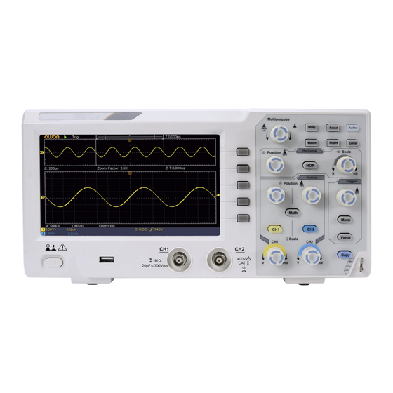
3. Quick Start Introduction to the Structure of the Oscilloscope This chapter makes a simple description of the operation and function of the front panel of the oscilloscope, enabling you to be familiar with the use of the oscilloscope in the shortest time. Front Panel The front panel has knobs and function buttons. -
Seite 12: Power On/Off
Display area Menu selection buttons: Select the right menu item. Control (button and knob) area Probe Compensation: Measurement signal (5V/1kHz) output. Signal Input Channel 6. USB Host port: It is used to transfer data when external USB equipment connects to the oscilloscope regarded as "host device". For example: Saving the waveform to USB flash disk needs to use this port. -
Seite 13: Control Area
equipment connects to the oscilloscope regarded as "slave device". For example: to use this port when connect PC to the oscilloscope by USB. Control Area Figure 3- 3 Control Area Overview 1. Function button area: Total 6 buttons. 2. Horizontal control area with 1 button and 2 knobs. "HOR"... - Seite 14 The Trigger Level knob is to adjust trigger voltage. Other 2 buttons refer to trigger system setting. 4. Copy button: This button is the shortcut for Save function in the Utility function menu. Pressing this button is equal to the Save option in the Save menu.
-
Seite 15: User Interface Introduction
User Interface Introduction Figure 3- 4 Illustrative Drawing of Display Interfaces 1. Waveform Display Area. 2. Run/Stop 3. The state of trigger, including: Auto: Automatic mode and acquire waveform without triggering. Trig: Trigger detected and acquire waveform. Ready: Pre-triggered data captured and ready for a trigger. Scan: Capture and display the waveform continuously. - Seite 16 7. It shows present triggering value and displays the site of present window in internal memory. 8. It indicates that there is a USB disk connecting with the oscilloscope. 9. Channel identifier of current menu. 10. The waveform of CH1. 11.
-
Seite 17: How To Implement The General Inspection
16. The frequency of the trigger signal. 17. The readings show current sample rate. 18. The readings indicate the corresponding Voltage Division and the Zero Point positions of the channels. "BW" indicates bandwidth limit. The icon shows the coupling mode of the channel. "—"... -
Seite 18: Check The Accessories
If it is found that the packaging carton or the foamed plastic protection cushion has suffered serious damage, do not throw it away first till the complete device and its accessories succeed in the electrical and mechanical property tests. 2. Check the Accessories The supplied accessories have been already described in the "... -
Seite 19: How To Implement The Probe Compensation
menu. Select Adjust in the left menu, select Default in the right menu. The default attenuation coefficient set value of the probe in the menu is 10X. 2. Set the Switch in the Oscilloscope Probe as 10X and Connect the Oscilloscope with CH1 Channel. Align the slot in the probe with the plug in the CH1 connector BNC, and then tighten the probe by rotating it to the right side. - Seite 20 make this adjustment to match the probe with the input channel. The probe which is not compensated or presents a compensation deviation will result in the measuring error or mistake. For adjusting the probe compensation, please carry out the following steps: Set the attenuation coefficient of the probe in the menu as 10X and that of the switch in the probe as 10X (see "How to Set the Probe Attenuation Coefficient"...
-
Seite 21: How To Set The Probe Attenuation Coefficient
Figure 3- 7 Adjust Probe How to Set the Probe Attenuation Coefficient The probe has several attenuation coefficients, which will influence the vertical scale factor of the oscilloscope. To change or check the probe attenuation coefficient in the menu of oscilloscope: (1) Push the function menu button of the used channels (CH1 or CH2 button). -
Seite 22: How To Use The Probe Safely
Figure 3- 8 Attenuation Switch Caution: When the attenuation switch is set to 1X, the probe will limit the bandwidth of the oscilloscope in 5MHz. To use the full bandwidth of the oscilloscope, the switch must be set to 10X. How to Use the Probe Safely The safety guard ring around the probe body protects your finger against any electric shock, shown as Figure 3- 9. -
Seite 23: How To Implement Self-Calibration
Warning: To avoid electric shock, always keep your finger behind the safety guard ring of the probe during the operation. To protect you from suffering from the electric shock, do not touch any metal part of the probe tip when it is connected to the power supply. - Seite 24 Figure 3- 10 Vertical Control Zone 1. Use the Vertical Position knob to show the signal in the center of the waveform window. The Vertical Position knob functions the regulating of the vertical display position of the signal. Thus, when the Vertical Position knob is rotated, the pointer of the earth datum point of the channel is directed to move up and down following the waveform.
-
Seite 25: Introduction To The Horizontal System
helpful when the trace position is far out of the screen and want it to get back to the screen center immediately. 2. Change the Vertical Setting and Observe the Consequent State Information Change. With the information displayed in the status bar at the bottom of the waveform window, you can determine any changes in the channel vertical scale factor. -
Seite 26: Introduction To The Trigger System
status bar changes accordingly. 2. Use the Horizontal Position knob to adjust the horizontal position of the signal in the waveform window. The Horizontal Position knob is used to control the triggering displacement of the signal or for other special applications. If it is applied to triggering the displacement, it can be observed that the waveform moves horizontally with the knob when you rotate the Horizontal Position knob. - Seite 27 the operations of the menu selection buttons, the trigger setting can be changed. 2. Use the Trigger Level knob to change the trigger level setting. By turning the Trigger Level knob, the trigger indicator on the screen will move up and down. With the movement of the trigger indicator, it can be observed that the trigger level value displayed in the screen changes accordingly.
-
Seite 28: Advanced User Guidebook
4. Advanced User Guidebook This chapter will deal with the following topics mainly: How to Set the Vertical System How to Set the Horizontal System How to Set the Trigger System How to Set the Sampling/Display How to Save and Recall Waveform ... -
Seite 29: How To Set The Vertical System
How to Set the Vertical System The VERTICAL CONTROLS includes three menu buttons such as CH1, CH2 and Math, and four knobs such as Vertical Position, Vertical Scale for each channel. Setting of CH1 and CH2 Each channel has an independent vertical menu and each item is set respectively based on the channel. - Seite 30 Match this to the probe attenuation factor to Probe 100X have an accurate reading of vertical scale. 1000X If you are measuring current by probing the MeasCurr voltage drop across a resistor, choose Yes. Turn the M knob to set the Amps/Volts ratio. The range is 100 mA/V - 1 KA/V.
- Seite 31 Taking the Channel 1 for example, the operation steps are shown as follows: (1) Push the CH1 button to show the CH1 SETUP menu. (2) In the right menu, select Inverted as ON, the waveform is inverted. Push again to switch to OFF, the waveform goes back to its original one.
-
Seite 32: Use Mathematical Manipulation Function
Use Mathematical Manipulation Function The Mathematical Manipulation function is used to show the results of the addition, multiplication, division and subtraction operations between two channels, or the FFT operation for a channel. Press the Math button to display the menu on the right. The Waveform Calculation Press the Math button to display the menu on the right, select Type as Math. -
Seite 33: Using Fft Function
1. Press the Math button to display the math menu in the right. The pink M waveform appears on the screen. 2. In the right menu, select Type as Math. 3. In the right menu, select Factor1 as CH1. 4. In the right menu, select Sign as +. 5. - Seite 34 Select CH1 as FFT source. Source Select CH2 as FFT source. Hamming Rectangle Blackman Window Select window for FFT. Hanning Kaiser Bartlett Vrms Select Vrms for Format. Format Select dB for Format. Next Page Enter next page Switch to select the horizontal frequency position or time base of the FFT Hori (Hz)
- Seite 35 4. In the right menu, select Window. Select the proper window type in the left menu. 5. In the right menu, select Format as Vrms or dB. 6. In the right menu, press Hori (Hz) to make the symbol in front of the frequency value, turn the M knob to adjust the horizontal position of FFT waveform;...
- Seite 36 Best solution for frequency, worst for magnitude. Best type for measuring the frequency spectrum of nonrepetitive signals and measuring frequency components near DC. Recommend to use for: Rectangle Transients or bursts, the signal level before and after the event are nearly equal.
- Seite 37 Good for magnitude, but poorer frequency resolution than Hamming. Recommend to use for: Sine, periodic and narrow band Hanning random noise. Transients or bursts where the signal levels before and after the event are significantly different. The frequency resolution when using the Kaiser window is fair;...
-
Seite 38: Use Vertical Position And Scale Knobs
DC component or offset can cause incorrect magnitude values of FFT waveform. To minimize the DC component, choose AC Coupling on the source signal. To reduce random noise and aliased components in repetitive or single-shot events, set the oscilloscope acquisition mode to average. -
Seite 39: How To Set The Horizontal System
Figure 4- 1 Information about Vertical Position How to Set the Horizontal System The HORIZONTAL CONTROLS includes the Horizontal HOR button and such knobs as Horizontal Position and Horizontal Scale. 1. Horizontal Position knob: this knob is used to adjust the horizontal positions of all channels (include those obtained from the mathematical manipulation), the analytic resolution of which changes with the time base. -
Seite 40: Zoom The Waveform
Zoom the Waveform Push the Horizontal HOR button to enter wave zoom mode. The top half of the display shows the Main window and the bottom half displays the Zoom window. The Zoom window is a magnified portion of the Main window. In normal mode, the Horizontal Position and Horizontal Scale knobs are used to adjust the horizontal position and time base of the Main window. -
Seite 41: Single Trigger
will acquire enough data continuously to draw the waveform on right of trigger point. Trigger control area consists of 1 knob and 2 menu buttons. Trigger Level: The knob that set the trigger level; push the knob and the level will be set as the vertical mid point values of the amplitude of the trigger signal. -
Seite 42: Edge Trigger
1. Edge Trigger An edge trigger occurs on trigger level value of the specified edge of input signal. Select Edge trigger mode to trigger on rising edge or falling edge. Push the Trigger Menu button to display the Trigger menu on the right. -
Seite 43: Video Trigger
Next Page Enter next page Block the direct current component. Coupling Allow all component pass. Trigger on rising edge Slope Trigger on falling edge 100 ns - 10 s, turn the M knob to set time Holdoff interval before another trigger occur. Holdoff Set Holdoff time as default value (100 ns). - Seite 44 In Video Trigger mode, the trigger setting information is displayed on bottom right of the screen, for example, ,indicates that trigger type is Video, trigger source is CH1, and Sync type is Even. Video Trigger menu list: MENU SETTIN INSTRUCTION Set vertical channel trigger type as single Type Single...
-
Seite 45: Alternate Trigger (Trigger Mode: Edge)
Alternate Trigger (Trigger mode: Edge) Trigger signal comes from two vertical channels when alternate trigger is on. This mode is used to observe two unrelated signals. Trigger mode is edge trigger. Alternate trigger (Trigger Type: Edge) menu list: Menu Settings Instruction Set vertical channel trigger type as Type... -
Seite 46: How To Set The Sampling/Display
Utility, Measure, Acquire, Cursor, and 2 immediate-execution buttons: Autoset, Run/Stop. How to Set the Sampling/Display Push the Acquire button, the Sampling and Display menu is shown in the right as follows:... - Seite 47 Setting Description Function Menu Sample Normal sampling mode. Peak Use to capture maximal and minimal Detect samples. Finding highest and lowest points over adjacent intervals. It is used for the detection of the jamming burr and Acqu Mode the possibility of reducing the confusion. Average It is used to reduce the random and don't-care...
- Seite 48 the picture tube oscilloscope can be simulated. The reserved original data is displayed in fade color and the new data is in bright color. (1) Push the Acquire button. (2) In the right menu, press Persist to select the persist time, including OFF, 1 Second, 2 Seconds, 5 Seconds and Infinity.
-
Seite 49: How To Save And Recall A Waveform
2. Select XY Mode as ON or OFF in the right menu. Counter It is a 6-digit single-channel counter. The counter can only measure the frequency of the triggering channel. The frequency range is from 2Hz to the full bandwidth. Only if the measured channel is in Edge mode of Single trigger type, the counter can be enabled. -
Seite 50: Recall Or Close The Waveform Stored In The Current Object
Choose the waveform to be saved. (Choose All to save all the Math Source waveforms that are turned on. You can save into the current internal object address, or into USB storage as a single file.) The object Wave0 –Wave15 are listed in the left menu, turn the M knob to choose the object which the waveform is saved to or recall... - Seite 51 Save the waveform of the source Save to the selected address. Save to internal storage or USB storage. When External Internal selected, the file name is editable. Storage Externa The BIN waveform file could be open waveform analysis software (on the supplied CD). Prev Page Enter previous page When the Type is selected as Configure, the menu is shown as the...
-
Seite 52: Recalling: In The Right Menu, Press Prev Page, And Press
Function Menu Setting Description Function Save Display the save function menu Type Image Choose the saving type as image. Save the current display screen. The file can be only stored in a USB storage, so a USB storage Save must be connected first. The file name is editable. - Seite 53 Object as ON, the waveform stored in the address will be shown, the address number and relevant information will be displayed at the top left of the screen. In order to save the waveform of CH1 and CH2 into the USB storage as a BIN file, the operation steps should be followed: 1.
- Seite 54 The screen image can only be stored in USB disk, so you should connect a USB disk with the instrument. 1. Install the USB disk: Insert the USB disk into the "7. USB Host port" of "Figure 3- 1 Front panel". If an icon appears on the top right of the screen, the USB disk is installed successfully.
- Seite 55 Figure 4- 2: Disk Management of computer 4. Right click 1 or 2 red mark area, choose Format. And system will pop up a warning message, click Yes. Figure 4- 3: Format the USB disk warning 5. Set File System as FAT32, Allocation unit size 4096. Check "Perform a quick format"...
- Seite 56 Figure 4- 4: Formatting the USB disk setting 6. Formatting process. Figure 4- 5: Formatting the USB disk...
- Seite 57 Check whether the USB disk is FAT32 with allocation unit size 4096 after formatting. Use Minitool Partition Wizard to format Download URL: http://www.partitionwizard.com/free-partition-manager.html Tip: There are many tools for the USB disk formatting on the market, just take Minitool Partition Wizard for example here. 1.
- Seite 58 4. Right click 1 or 2 red mark area, choose Format. Figure 4- 7: Choose format 5. Set File System FAT32, Cluster size 4096. Click OK. Figure 4- 8: Format setting 6. Click Apply at the top left of the menu. Then click Yes on the pop-up warning to begin formatting.
- Seite 59 Figure 4- 9: Apply setting 7. Formatting process Figure 4- 10: Format process Format the USB disk successfully Figure 4- 11: Format successfully...
-
Seite 60: How To Implement The Auxiliary System Function Setting
How to Implement the Auxiliary System Function Setting ●Config Push the Utility button, select Function in the right menu, select Configure in the left menu. The description of Configure Menu is shown as the follows: Function Setting Description Menu Configure Function Show the configure menu Lock all keys. -
Seite 61: Function Menu
Function Setting Description Menu Display Function Show the display menu Turn the M knob to adjust the BackLight 0% - 100% backlight. Graticule Select the grid type OFF, 5S – Turn the M knob to set the disappear Menu Time time of menu ●Adjust Push the Utility button, select Function in the right menu, select... - Seite 62 Do Self Cal (Self-Calibration) The self-calibration procedure can improve the accuracy of the oscilloscope under the ambient temperature to the greatest extent. If the change of the ambient temperature is up to or exceeds 5℃, the self-calibration procedure should be executed to obtain the highest level of accuracy.
-
Seite 63: How To Update Your Instrument Firmware
Use the front-panel USB port to update your instrument firmware using a USB memory device. Refer to "How to Update your Instrument Firmware" on page 62. How to Update your Instrument Firmware Use the front-panel USB port to update your instrument firmware using a USB memory device. -
Seite 64: How To Measure Automatically
In the right menu, select Start again, the interfaces below will be displayed in sequence. The update process will take up to three minutes. After completion, the instrument will be shut down automatically. Press the button to power on the instrument. How to Measure Automatically Push the Measure button to display the menu for the settings of... - Seite 65 the Automatic Measurements. At most 8 types of measurements could be displayed on the bottom left of the screen. The oscilloscopes provide 30 parameters for auto measurement, including Period, Frequency, Mean, PK-PK, RMS, Max, Min, Top, Base, Amplitude, Overshoot, Preshoot, Rise Time, Fall Time, +PulseWidth, -PulseWidth, +Duty Cycle, -Duty Cycle, Delay A→B , Delay A→B , Cycle RMS, Cursor RMS, Screen Duty, Phase, +PulseCount,...
- Seite 66 Measure Only if the waveform channel is in the ON state, the measurement can be performed. The automatic measurement can not be performed in the following situation: 1) On the saved waveform. 2) On the Dual Wfm Math waveform. 3) On the Video trigger mode. On the Scan format, period and frequency can not be measured.
- Seite 67 Figure 4- 12 Automatic measurement The automatic measurement of voltage parameters The oscilloscopes provide automatic voltage measurements including Mean, PK-PK, RMS, Max, Min, Vtop, Vbase, Vamp, OverShoot, PreShoot, Cycle RMS, and Cursor RMS. Figure 4- 13 below shows a pulse with some of the voltage measurement points.
- Seite 68 Figure 4- 13 Mean: The arithmetic mean over the entire waveform. PK-PK: Peak-to-Peak Voltage. RMS: The true Root Mean Square voltage over the entire waveform. Max: The maximum amplitude. The most positive peak voltage measured over the entire waveform. Min: The minimum amplitude. The most negative peak voltage measured over the entire waveform.
- Seite 69 entire period of the waveform. Cursor RMS: The true Root Mean Square voltage over the range of two cursors. The automatic measurement of time parameters The oscilloscopes provide time parameters auto-measurements include Period, Frequency, Rise Time, Fall Time, +D width, -D width, +Duty, -Duty, Delay A→B , Delay A→B , and Duty...
-
Seite 70: Pulsecount
-D width: The width of the first negative pulse in the 50% amplitude points. +Duty: +Duty Cycle, defined as +Width/Period. -Duty:-Duty Cycle, defined as -Width/Period. Delay A→B : The delay between the two channels at the rising edge. Delay A→B : The delay between the two channels at the falling edge. -
Seite 71: How To Measure With Cursors
and the unit is voltage-second. The area measured above the zero reference (namely the vertical offset) is positive; the area measured below the zero reference is negative. The area measured is the algebraic sum of the area of the whole waveform within the screen. - Seite 72 Line Type Time Makes the vertical cursors active. (Time&V Voltage Makes the horizontal cursors active. oltage type) Window Main Measure in the main window. (Wave Extension Measure in the extension window. zoom mode) Turn the M knob to move line a. Turn the M knob to move line b.
- Seite 73 or b, turn the M knob to move it. 6. Push the horizontal HOR button to enter wave zoom mode. Push Cursor to show the right menu, select Window as Main or Extension to make the cursors shown in the main window or zoom window.
- Seite 74 The Cursor Measurement for FFT mode In FFT mode, push the Cursor button to turn cursors on and display the cursor menu. The description of the cursor menu in FFT mode is shown as the following table: Functio Setting Description n Menu Vamp Display the Vamp measurement cursor...
-
Seite 75: Press The First Menu Item In The Right Menu, Select
Type Vamp Makes the horizontal cursors active. (Freq&Va mp type) Window Main Measure in the main window. (Wave Extension Measure in the FFT extension window. zoom mode) Turn the M knob to move line a. Turn the M knob to move line b. Line Two cursors are linked. -
Seite 76: How To Use Executive Buttons
or b, turn the M knob to move it. 7. In the right cursor menu, you can select Window as Main to make the cursors shown in the main window. How to Use Executive Buttons Executive Buttons include Autoset, Run/Stop, Copy. [Autoset] button ... - Seite 77 Judge waveform type by Autoset Five kinds of types: Sine, Square, video signal, DC level, Unknown signal. Menu as follow: Waveform Menu Sine Multi-period, Single-period, FFT, Cancel Autoset Square Multi-period, Single-period, Rising Edge, Falling Edge, Cancel Autoset Video signal Type (line, field), Odd, Even, Line NO., Cancel Autoset DC level/Unknown Cancel Autoset...
- Seite 78 Notice: When there is no sampling at STOP state, the vertical division and the horizontal time base of the waveform still can be adjusted within a certain range, in other words, the signal can be expanded in the horizontal or vertical direction. When the horizontal time base is ≤50ms, the horizontal time base can be expanded for 4 divisions downwards.
-
Seite 79: Communication With Pc
5. Communication with PC The oscilloscope supports communications with a PC through USB. You can use the Oscilloscope communication software to store, analyze, display the data and remote control. To learn about how to operate the software, you can push F1 in the software to open the help document. -
Seite 80: Demonstration
6. Demonstration Example 1: Measurement a Simple Signal The purpose of this example is to display an unknown signal in the circuit, and measure the frequency and peak-to-peak voltage of the signal. 1. Carry out the following operation steps for the rapid display of this signal: (1) Set the probe menu attenuation coefficient as 10X and that of the switch in the probe switch as 10X (see "How to Set the... -
Seite 81: Example 2: Gain Of A Amplifier In A Metering Circuit
(5) In the left Type menu, turn the M knob to select Frequency. (6) In the right menu, select AddCH1. The frequency type is added. The measured value will be displayed at the bottom left of the screen automatically (see Figure 6- 1). Figure 6- 1 Measure period and frequency value for a given signal Example 2: Gain of a Amplifier in a Metering Circuit... -
Seite 82: Operation Steps
Coefficient" on P20). Connect the oscilloscope CH1 channel with the circuit signal input end and the CH2 channel to the output end. Operation Steps: (1)Push the Autoset button and the oscilloscope will automatically adjust the waveforms of the two channels into the proper display state. -
Seite 83: Example 3: Capturing A Single Signal
Figure 6- 2 Waveform of Gain Measurement Example 3: Capturing a Single Signal It's quite easy to use Digital Oscilloscope to capture non-periodic signal, such as a pulse and burr etc. But the common problem is how to set up a trigger if you have no knowledge of the signal? For example, if the pulse is the logic signal of a TTL level, the trigger level should be set to 2 volts and the trigger edge be set as the rising edge trigger. - Seite 84 switch in the probe to 10X (see "How to Set the Probe Attenuation Coefficient" on P20). (2)Adjust the Vertical Scale and Horizontal Scale knobs to set up a proper vertical and horizontal ranges for the signal to be observed. (3)Push the Acquire button to display the right menu. (4)In the right menu, select Acqu Mode as Peak Detect.
-
Seite 85: Example 4: Analyze The Details Of A Signal
making an easy observation of the waveform before the burr occurs (see Figure 6- 3). Figure 6- 3 Capturing a Single Signal Example 4: Analyze the Details of a Signal Noise is very common inside most of the electronic signal. To find out what's inside the noise and reduce the level of noise is very important function our oscilloscope is capable to offer. - Seite 86 turning on Peak Detect function and changing time base to slow down the incoming signal, any peaks or burr would be detected by the function (see Figure 6- 4). Figure 6- 4 Signal with Noises Separate Noises from the Signal When focusing on signal itself, the important thing is to reduce the noise level as lower as possible, this would enable user to have more details about the signal.
-
Seite 87: Example 5: Application Of X-Y Function
easy to see more details of the signal itself. After applying Average, user can easily identify the burrs on the rising and falling edges of some part of the signal (see Figure 6- 5). Figure 6- 5 Reduce Noise level by using Average function Example 5: Application of X-Y Function Examine the Phase Difference between Signals of two Channels Example: Test the phase change of the signal after it passes through... - Seite 88 steps: (1)Set the probe menu attenuation coefficient for 10X and that of the switch in the probe for 10X (see "How to Set the Probe Attenuation Coefficient" on P20). (2)Connect the probe of channel 1 to the input of the network and that of Channel 2 to the output of the network.
- Seite 89 The signal must be centered and kept in the horizontal direction. Figure 6- 6 Lissajous Graph Based on the expression sin (q) =A/B or C/D, thereinto, q is the phase difference angle, and the definitions of A, B, C, and D are shown as the graph above.
-
Seite 90: Example 6: Video Signal Trigger
Example 6: Video Signal Trigger Observe the video circuit of a television, apply the video trigger and obtain the stable video output signal display. Video Field Trigger For the trigger in the video field, carry out operations according to the following steps: (1)Push the Trigger Menu button to display the right menu. - Seite 91 Figure 6- 7 Waveform Captured from Video Field Trigger...
-
Seite 92: Troubleshooting
7. Troubleshooting 1. Oscilloscope is powered on but no Display. Check whether the power connection is connected properly. Restart the instrument after completing the checks above. If the problem persists, please contact us and we will be under your service. - Seite 93 the proper position. Only if a proper trigger mode is applied, the waveform can be displayed steadily. 5. No Display Responses to the Push-down of Run/Stop. Check whether Normal or Signal is chosen for Polarity in the TRIG MODE menu and the trigger level exceeds the waveform range.
-
Seite 94: Technical Specifications
8. Technical Specifications Unless otherwise specified, the technical specifications applied are for the oscilloscope only, and Probes attenuation set as 10X. Only if the oscilloscope fulfills the following two conditions at first, these specification standards can be reached. This instrument should run for at least 30 minutes continuously under the specified operating temperature. - Seite 95 Performance Characteristics Instruction Time delay between 150ps channel(typical) Bandwidth limit 20 MHz, full bandwidth Sampling rate 0.5 S/s~1 GS/s range Interpolation (Sinx)/x Record length Scanning speed 2 ns/div – 1000 s/div, (S/div) step by 1 – 2 - 5 Sampling rate / Horizontal relay time ±100 ppm...
- Seite 96 Performance Characteristics Instruction ≥10 Hz (at input, AC coupling, -3 Low Frequency Rise time (at ≤ 3.5 ns input, Typical) DC gain ±3% accuracy Delta Volts between any two averages of ≥16 waveforms DC accuracy acquired with the same scope (average) setup and ambient conditions (△V):...
-
Seite 97: Performance Characteristics
Performance Characteristics Instruction Waveform 16 waveforms storage Bandwid Full bandwidth Lissajo Phase figure differenc ±3 degrees Communic USB 2.0 (USB storage) ation port Counter Support Trigger: Performance Characteristics Instruction Trigger level Internal ±5 div from the screen center range Trigger level Accuracy Internal ±0.3 div... -
Seite 98: General Technical Specifications
Performance Characteristics Instruction Edge trigger slope Rising, Falling Support standard NTSC, PAL Modulation and SECAM broadcast systems Video Trigger Line number 1-525 (NTSC) and 1-625 range (PAL/SECAM) General Technical Specifications Display Display Type 7" Colored LCD (Liquid Crystal Display) Display 800 (Horizontal) ×... - Seite 99 Environment Working temperature: 0 ℃ - 40 ℃ Temperature Storage temperature: -20 ℃ - 60 ℃ Relative Humidity ≤ 90% Operating: 3,000 m Height Non-operating: 15,000 m Cooling Method Natural cooling Mechanical Specifications Dimension 300 mm× 155 mm×70 mm (L*H*W) Weight About 1.4 kg Interval Period of Adjustment:...
-
Seite 100: Appendix
9. Appendix Appendix A: Enclosure (The accessories subject to final delivery.) Standard Accessories: Power Cord CD Rom Quick Guide USB Cable Probe Probe Adjust Options: Soft Bag Appendix B: General Care and Cleaning General Care... - Seite 101 Do not store or leave the instrument where the liquid crystal display will be exposed to direct sunlight for long periods of time. Caution: To avoid any damage to the instrument or probe, do not exposed it to any sprays, liquids, or solvents. Cleaning Inspect the instrument and probes as often as operating conditions require.
- Seite 102 Manufacturer: Shanghaimuxinmuyeyouxiangongsi Address: Shuangchenglu 803nong11hao1602A-1609shi, baoshanqu, shanghai 200000 CN. Imported to AUS: SIHAO PTY LTD. 1 ROKEVA STREETEASTWOOD NSW 2122 Australia Imported to USA: Sanven Technology Ltd. Suite 250, 9166 Anaheim Place, Rancho Cucamonga, CA 91730 E-CrossStu GmbH Mainzer Landstr.69, 60329 Frankfurt am Main. YH CONSULTING LIMITED.
- Seite 104 Technical Support and E-Warranty Certificate www.vevor.com/support...
- Seite 105 Machine Translated by Google Assistance t echnique e t c ertificat d e g arantie é lectronique h ttps://www.vevor.com/support OSCILLOSCOPES MANUEL D 'UTILISATION MODÈLE N ° : S DS1102 Nous c ontinuons à n ous e ngager à v ous f ournir d es o utils à d es p rix c ompétitifs.
- Seite 106 Assistance t echnique e t c ertificat d e g arantie électronique w ww.vevor.com/support Il s 'agit d e l a n otice d 'utilisation d 'origine. V euillez l ire a ttentivement t outes l es i nstructions d u ...
- Seite 107 Machine Translated by Google Table d es m atières 1. E xigences g énérales d e s écurité .......... 5 2. T ermes e t s ymboles d e s écurité..............7 3. D émarrage r apide................ 1 0 Introduction à l a s tructure d e l 'oscilloscope........10 Panneau ...
- Seite 108 Machine Translated by Google Comment r égler l e s ystème d e d éclenchement.......... 3 9 Déclencheur u nique....................40 Déclencheur a lternatif ( mode d e d éclenchement : E dge)........44 Comment u tiliser l e m enu d e f onctions..........44 Comment ...
-
Seite 109: E Xigences G Énérales D E S Écurité
Machine Translated by Google 1. E xigences g énérales d e s écurité Avant u tilisation, v euillez l ire l es p récautions d e s écurité s uivantes p our é viter t out d'éventuelles b lessures c orporelles e t p our e mpêcher c e p roduit o u t out a utre produits ... - Seite 110 Machine Translated by Google utilisation u ltérieure. U tilisez v otre o scilloscope d ans u n e ndroit b ien a éré. A ssurezvous q ue l'instrument e st i nstallé a vec u ne v entilation a déquate. ...
-
Seite 111: T Ermes E T S Ymboles D E S Écurité
Machine Translated by Google 2. T ermes e t s ymboles d e s écurité Termes d e s écurité Termes u tilisés d ans c e m anuel ( Les t ermes s uivants p euvent a pparaître d ans c e m anuel) : Avertissement : ... - Seite 112 Machine Translated by Google Pour é viter d 'endommager l e c orps e t l e p roduit e t l es é quipements c onnectés, l isez attentivement l es c onsignes d e s écurité s uivantes a vant d 'utiliser l 'outil d e t est. C e produit ...
- Seite 113 Machine Translated by Google Avertissement: Pour é viter t out i ncendie o u c hoc é lectrique, l orsque l 'entrée d e l 'oscilloscope le s ignal c onnecté e st s upérieur à 4 2 V c rête ( 30 V rms) o u a ctivé circuits ...
-
Seite 114: D Émarrage R Apide
Machine Translated by Google 3. D émarrage r apide Introduction à l a s tructure d e l a Oscilloscope Ce c hapitre f ait u ne d escription s imple d u f onctionnement e t d e l a f onction du ... -
Seite 115: Panneau A Rrière
Machine Translated by Google 1. Z one d 'affichage 2. B outons d e s élection d e m enu : s électionnez l ’élément d e m enu a pproprié. 3. Z one d e c ontrôle ( boutons e t m olette) 4. ... -
Seite 116: Zone D E C Ontrôle
Machine Translated by Google l'équipement c onnecté à l 'oscilloscope e st c onsidéré c omme u n « appareil e sclave ». Par e xemple : p our u tiliser c e p ort l ors d e l a c onnexion d u P C à l 'oscilloscope e n USB. - Seite 117 Machine Translated by Google Le b outon d e n iveau d e d éclenchement p ermet d e r égler l a t ension d e d éclenchement. 2 a utres b outons reportezvous a u r églage d u s ystème d e d éclenchement. 4. ...
-
Seite 118: Présentation D E L 'Interface U Tilisateur
Machine Translated by Google Présentation d e l 'interface u tilisateur Figure 3 4 D essin i llustratif d es i nterfaces d 'affichage 1. Z one d ’affichage d e l a f orme d ’onde. 2. E xécution/Arrêt 3. ... - Seite 119 Machine Translated by Google 7. I l a ffiche l a v aleur d e d éclenchement a ctuelle e t a ffiche l e s ite d e fenêtre p résente d ans l a m émoire i nterne. 8. ...
-
Seite 120: Comment M Ettre E N Œ Uvre L 'Inspection G Énérale
Machine Translated by Google 16. L a f réquence d u s ignal d e d éclenchement. 17. L es l ectures i ndiquent l e t aux d 'échantillonnage a ctuel. 18. L es l ectures i ndiquent l a d ivision d e t ension c orrespondante et ... -
Seite 121: Comment I Mplémenter L A F Onction I Nspection
Machine Translated by Google Si v ous c onstatez q ue l e c arton d 'emballage o u l e c oussin d e p rotection e n plastique e xpansé a s ubi d e g raves d ommages, n e l e j etez p as a vant q ue l'appareil ... -
Seite 122: Comment M Ettre E N ΠUvre L A C Ompensation D E S Onde
Machine Translated by Google menu. S électionnez A juster d ans l e m enu d e g auche, s électionnez P ar d éfaut d ans l e m enu d e d roite menu. L a v aleur p ar d éfaut d u c oefficient d 'atténuation d e l a s onde dans ... - Seite 123 Machine Translated by Google effectuez c e r églage p our f aire c orrespondre l a s onde a vec l e c anal d 'entrée. sonde q ui n 'est p as c ompensée o u p résente u ne c ompensation tout ...
-
Seite 124: Comment R Égler L E C Oefficient D 'Atténuation D E L A S Onde
Machine Translated by Google Figure 3 7 R églage d e l a s onde Comment r égler l e c oefficient d 'atténuation d e l a s onde La s onde p ossède p lusieurs c oefficients d 'atténuation, q ui i nfluenceront le ... -
Seite 125: Comment U Tiliser L A S Onde E N T Oute S Écurité
Machine Translated by Google Figure 3 8 I nterrupteur d 'atténuation Prudence: Lorsque l e c ommutateur d 'atténuation e st r églé s ur 1 X, l a s onde l imite l a bande p assante d e l 'oscilloscope à 5 M Hz. P our u tiliser t oute l a b ande passante ... -
Seite 126: Comment M Ettre E N Œ Uvre L 'Autoétalonnage
Machine Translated by Google Avertissement: Pour é viter l es c hocs é lectriques, g ardez t oujours v otre d oigt d errière la b ague d e p rotection d e s écurité d e l a s onde p endant l 'opération. Pour ... - Seite 127 Machine Translated by Google Figure 3 1 0 Z one d e c ontrôle v erticale 1. U tilisez l e b outon d e p osition v erticale p our a fficher l e s ignal a u c entre d e l a f enêtre d e forme ...
-
Seite 128: Introduction A U S Ystème H Orizontal
Machine Translated by Google utile l orsque l a p osition d e l a t race e st l oin d e l 'écran e t q ue v ous l e s ouhaitez pour r evenir i mmédiatement a u c entre d e l 'écran. 2. ... -
Seite 129: Introduction A U S Ystème D E D Éclenchement
Machine Translated by Google la b arre d 'état c hange e n c onséquence. 2. U tilisez l e b outon P osition h orizontale p our r égler l a p osition h orizontale d u s ignal d ans l a fenêtre ... - Seite 130 Machine Translated by Google les o pérations d es b outons d e s élection d e m enu, l e r églage d u d éclencheur p eut être c hangé. 2. U tilisez l e b outon d e n iveau d e d éclenchement p our m odifier l e r églage d u n iveau d e d éclenchement. En ...
-
Seite 131: G Uide D 'Utilisation A Vancé
Machine Translated by Google 4. G uide d 'utilisation a vancé Ce c hapitre t raitera p rincipalement d es s ujets s uivants : C omment r égler l e s ystème v ertical C omment d éfinir l e s ystème h orizontal ... -
Seite 132: Comment R Égler L E S Ystème V Ertical
Machine Translated by Google Comment r égler l e s ystème v ertical Les C OMMANDES V ERTICALES c omprennent t rois b outons d e m enu t els q ue CH1, C H2 e t M ath, e t q uatre b outons t els q ue l a p osition v erticale, l 'échelle v erticale pour ... - Seite 133 Machine Translated by Google Faites c orrespondre c ela a u f acteur d 'atténuation d e l a s onde p our Sonde 100X avoir u ne l ecture p récise d e l 'échelle v erticale. 1000X Si v ous m esurez l e c ourant e n s ondant l e CourbeMes Chute ...
- Seite 134 Machine Translated by Google En p renant l e c anal 1 c omme e xemple, l es é tapes d e f onctionnement s ont p résentées c omme s uit : suit: (1) A ppuyez s ur l e b outon C H1 p our a fficher l e m enu C H1 S ETUP. (2) ...
-
Seite 135: Utiliser L A F Onction D E M Anipulation M Athématique
Machine Translated by Google Utiliser l a f onction d e m anipulation m athématique La f onction d e m anipulation m athématique e st u tilisée p our a fficher l e résultats d e l 'addition, d e l a m ultiplication, d e l a d ivision e t d e l a s oustraction opérations ... -
Seite 136: Utilisation D E L A F Onction F Ft
Machine Translated by Google 1. A ppuyez s ur l e b outon M ath p our a fficher l e m enu m athématique à d roite. une f orme d 'onde M r ose a pparaît s ur l 'écran. 2. ... - Seite 137 Machine Translated by Google Sélectionnez C H1 c omme s ource F FT. Source Sélectionnez C H2 c omme s ource F FT. Hamming Rectangle Homme n oir Fenêtre Sélectionnez l a f enêtre p our F FT. Hanning kaiser Bartlett Vrms Sélectionnez ...
- Seite 138 Machine Translated by Google 4. D ans l e m enu d e d roite, s électionnez F enêtre. S électionnez l e t ype d e f enêtre a pproprié dans l e m enu d e g auche. 5. ...
- Seite 139 Machine Translated by Google Meilleure s olution p our l a f réquence, p ire p our ampleur. Meilleur t ype p our m esurer l a f réquence spectre d e s ignaux n on r épétitifs e t mesure ...
- Seite 140 Machine Translated by Google Bon p our l 'amplitude, m ais r ésolution e n fréquence p lus f aible q ue H amming. Recommandé p our : B ruit a léatoire s inusoïdal, p ériodique e t à Hanning bande ...
-
Seite 141: Utiliser L Es B Outons D E P Osition V Erticale E T D 'Échelle
Machine Translated by Google L e c omposant C C o u l e d écalage p eut e ntraîner d es v aleurs d 'amplitude i ncorrectes Forme d 'onde F FT. P our m inimiser l a c omposante C C, c hoisissez C A Couplage ... -
Seite 142: Comment R Égler L E S Ystème H Orizontal
Machine Translated by Google Figure 4 1 I nformations s ur l a p osition v erticale Comment r égler l e s ystème h orizontal Les C OMMANDES H ORIZONTALES i ncluent l es C OMMANDES H ORIZONTALES bouton ... -
Seite 143: Zoom S Ur L A F Orme D 'Onde
Machine Translated by Google Zoom s ur l a f orme d 'onde Appuyez s ur l e b outon H OR h orizontal p our a ccéder a u m ode z oom d es v agues. L a m oitié s upérieure de ... -
Seite 144: Déclencheur U Nique
Machine Translated by Google acquerra s uffisamment d e d onnées e n c ontinu p our d essiner l a f orme d 'onde à d roite du p oint d e d éclenchement. La z one d e c ontrôle d u d éclencheur s e c ompose d 'un b outon e t d e d eux b outons d e m enu. Niveau ... - Seite 145 Machine Translated by Google 1. D éclencheur d e b ord Un d éclenchement d e f ront s e p roduit s ur l a v aleur d u n iveau d e d éclenchement d u f ront s pécifié d e signal ...
- Seite 146 Machine Translated by Google Page s uivante Accéder à l a p age s uivante Bloquer l e c omposant c ourant c ontinu. Couplage Autoriser l e p assage d e t ous l es c omposants. Déclenchement s ur f ront m ontant Pente Déclenchement ...
- Seite 147 Machine Translated by Google En m ode D éclencheur v idéo, l es i nformations d e r églage d u d éclencheur s ont a ffichées s ur , i ndique en b as à d roite d e l 'écran, p ar e xemple, ce ...
-
Seite 148: Déclencheur A Lternatif ( Mode D E D Éclenchement : E Dge)
Machine Translated by Google Déclencheur a lternatif ( mode d e d éclenchement : E dge) Le s ignal d e d éclenchement p rovient d e d eux c anaux v erticaux e n a lternance le d éclencheur e st a ctivé. C e m ode e st u tilisé p our o bserver d eux s ignaux s ans r apport. Le ... -
Seite 149: Comment R Égler L 'Échantillonnage/L'affichage
Machine Translated by Google Utilitaire, M esure, A cquisition, C urseur e t 2 b outons d 'exécution i mmédiate : Autoset, E xécuter/Arrêter. Comment r égler l 'échantillonnage/l'affichage Appuyez s ur l e b outon A cquérir , l e m enu É chantillonnage e t a ffichage s 'affiche à ... - Seite 150 Machine Translated by Google Fonction Description d u p aramètre Menu Échantillon Mode d 'échantillonnage n ormal. Culminer Utilisé p our c apturer d es é chantillons m aximaux e t m inimaux. Détecter Recherche d es p oints l es p lus h auts e t l es p lus b as s ur d es intervalles ...
- Seite 151 Machine Translated by Google L'oscilloscope à t ube c athodique p eut ê tre s imulé. L 'original r éservé les d onnées s ont a ffichées e n c ouleur p âle e t l es n ouvelles d onnées s ont e n c ouleur v ive. (1) ...
-
Seite 152: Comment E Nregistrer E T R Appeler U Ne F Orme D 'Onde
Machine Translated by Google 2. S électionnez l e m ode X Y s ur O N o u O FF d ans l e m enu d e d roite. Comptoir Il s 'agit d 'un c ompteur m onocanal à 6 c hiffres. L e c ompteur n e p eut m esurer q ue la ... - Seite 153 Machine Translated by Google Choisissez l a f orme d ’onde à e nregistrer. (Choisissez T out p our e nregistrer t outes l es Mathématiques Source formes d ’onde a ctivées. Tous Vous p ouvez e nregistrer d ans l 'adresse d e l 'objet interne ...
- Seite 154 Machine Translated by Google Enregistrez l a f orme d ’onde d e l a s ource à l ’adresse Sauvegarder sélectionnée. Enregistrer s ur l a m émoire i nterne o u s ur l a mémoire U SB. L orsque E xterne e st s électionné, l e Interne nom ...
- Seite 155 Machine Translated by Google Description d es p aramètres d u m enu d e f onctions Fonction Enregistrer A fficher l e m enu d e l a f onction d e s auvegarde Taper Image C hoisissez l e t ype d 'enregistrement e n t ant q u'image. Enregistrer ...
- Seite 156 Machine Translated by Google Objet c omme O N, l a f orme d 'onde s tockée d ans l 'adresse s era a ffichée, le n uméro d 'adresse e t l es i nformations p ertinentes s eront a ffichés à en ...
- Seite 157 Machine Translated by Google L'image d e l 'écran n e p eut ê tre s tockée q ue s ur u n d isque U SB, v ous d evez d onc connecter u n d isque U SB à l 'instrument. 1. ...
- Seite 158 Machine Translated by Google Figure 4 2 : G estion d es d isques d e l 'ordinateur 4. C liquez a vec l e b outon d roit s ur 1 o u 2 z ones d e m arquage r ouge, c hoisissez F ormat. E t l e s ystème v a un ...
- Seite 159 Machine Translated by Google Figure 4 4 : F ormatage d es p aramètres d u d isque U SB 6. P rocessus d e f ormatage. Figure 4 5 : F ormatage d u d isque U SB...
- Seite 160 Machine Translated by Google 7. V érifiez s i l e d isque U SB e st F AT32 a vec u ne t aille d 'unité d 'allocation 4096 a près f ormatage. Utilisez M initool P artition W izard p our f ormater URL: Télécharger ...
- Seite 161 Machine Translated by Google 4. C liquez a vec l e b outon d roit s ur 1 o u 2 z ones d e m arque r ouge, c hoisissez F ormat. Figure 4 7 : C hoisir l e f ormat 5. ...
- Seite 162 Machine Translated by Google Figure 4 9 : A ppliquer l e p aramètre 7. P rocessus d e f ormatage Figure 4 10 : P rocessus d e f ormatage 8. F ormater l e d isque U SB a vec s uccès Figure ...
- Seite 163 Machine Translated by Google Comment m ettre e n œ uvre l e s ystème a uxiliaire Réglage d es f onctions •Config Appuyez s ur l e b outon U tilitaire , s électionnez F onction d ans l e m enu d e d roite, s électionnez Configurer ...
- Seite 164 Machine Translated by Google Fonction Description Paramètre Menu Fonction Affichage A fficher l e m enu d 'affichage Tournez l e b outon M p our r égler l e Rétroéclairage 0 % 1 00% rétroéclairage. Réticule Sélectionnez ...
- Seite 165 Machine Translated by Google Faire u n a utoétalonnage ( autocalibrage) La p rocédure d 'autoétalonnage p eut a méliorer l a p récision d e l ' oscilloscope à t empérature a mbiante d ans l a m esure d u p ossible. S i le ...
- Seite 166 Machine Translated by Google Utilisez l e p ort U SB d u p anneau a vant p our m ettre à j our l e m icrologiciel d e v otre i nstrument à l 'aide d 'un p ériphérique d e s tockage U SB. R eportezvous à « Comment m ettre à j our v otre « Micrologiciel ...
-
Seite 167: Automatiquement
Machine Translated by Google 6. D ans l e m enu d e d roite, s électionnez à n ouveau D émarrer , l es i nterfaces c idessous s eront affichés e n s équence. L e p rocessus d e m ise à j our p rendra j usqu'à t rois minutes. ... - Seite 168 Machine Translated by Google les m esures a utomatiques. A u p lus 8 t ypes d e m esures p euvent ê tre s'affiche e n b as à g auche d e l 'écran. Les o scilloscopes f ournissent 3 0 p aramètres p our l a m esure a utomatique, y ...
- Seite 169 Machine Translated by Google Mesure Seulement s i l e c anal d e f orme d 'onde e st à l 'état O N, l a m esure peut ê tre e ffectuée. L a m esure a utomatique n e p eut p as ê tre effectué ...
- Seite 170 Machine Translated by Google Figure 4 1 2 M esure a utomatique La m esure a utomatique d es p aramètres d e t ension Les o scilloscopes f ournissent d es m esures d e t ension a utomatiques, notamment ...
- Seite 171 Machine Translated by Google Figure 4 13 Moyenne : L a m oyenne a rithmétique s ur l ’ensemble d e l a f orme d ’onde. PKPK : T ension c rête à c rête. RMS : L a v raie t ension m oyenne q uadratique s ur l 'ensemble d e l a forme ...
- Seite 172 Machine Translated by Google période e ntière d e l a f orme d 'onde. Curseur R MS : L a t ension q uadratique m oyenne r éelle s ur l a p lage de d eux c urseurs. La m esure a utomatique d es p aramètres t emporels Les ...
-
Seite 173: Autres M Esures
Machine Translated by Google D l argeur : L a l argeur d e l a p remière i mpulsion n égative d ans l es 5 0 % points d 'amplitude. +Duty : + Cycle d e s ervice, d éfini c omme + Largeur/Période. Service : Cycle ... -
Seite 174: Comment M Esurer A Vec D Es C Urseurs
Machine Translated by Google et l 'unité e st l a t ensionseconde. L a z one m esurée a udessus d e l a la r éférence z éro ( à s avoir l e d écalage v ertical) e st p ositive ; l a z one mesurée ... - Seite 175 Machine Translated by Google Doubler Taper Temps Rend l es c urseurs v erticaux a ctifs. (Temps e t V Rend l es c urseurs h orizontaux a ctifs. Tension tension taper) Fenêtre Mesurer d ans l a f enêtre p rincipale. Principal (Vague Extension...
- Seite 176 Machine Translated by Google ou b , t ournez l e b outon M p our l e d éplacer. 6. A ppuyez s ur l e b outon h orizontal H OR p our a ccéder a u m ode z oom d es v agues. Appuyez ...
- Seite 177 Machine Translated by Google Mesure d u c urseur p our l e m ode F FT En m ode F FT, a ppuyez s ur l e b outon C urseur p our a ctiver l es c urseurs e t a fficher le ...
- Seite 178 Machine Translated by Google Taper Vamp r end l es c urseurs h orizontaux a ctifs. (Fréq&Va type d e d éputé) Fenêtre Mesurer d ans l a f enêtre p rincipale. Principal (Vague zoom Extension Mesure d ans l a f enêtre d 'extension F FT. mode) Tournez ...
-
Seite 179: Comment U Tiliser L Es B Outons E Xécutifs
Machine Translated by Google ou b , t ournez l e b outon M p our l e d éplacer. 7. D ans l e m enu d u c urseur d e d roite, v ous p ouvez s électionner F enêtre c omme p rincipale p our rendre ... - Seite 180 Machine Translated by Google Juger l e t ype d e f orme d 'onde p ar A utoset Cinq t ypes d e s ignaux : s inusoïdal, c arré, s ignal v idéo, n iveau C C, Signal i nconnu. Menu ...
- Seite 181 Machine Translated by Google Remarque : l orsqu'il n 'y a p as d 'échantillonnage à l 'état S TOP, l a d ivision v erticale et l a b ase d e t emps h orizontale d e l a f orme d 'onde p euvent t oujours ê tre a justées dans ...
-
Seite 182: C Ommunication A Vec L E P C
Machine Translated by Google 5. C ommunication a vec l e P C L'oscilloscope p rend e n c harge l es c ommunications a vec u n P C v ia U SB. Vous p ouvez u tiliser l e l ogiciel d e c ommunication O scilloscope p our s tocker, a nalyser, afficher ... -
Seite 183: D Émonstration
Machine Translated by Google 6. D émonstration Exemple 1 : M esure d 'un s ignal s imple Le b ut d e c et e xemple e st d 'afficher u n s ignal i nconnu d ans le c ircuit e t m esurer l a f réquence e t l a t ension c rête à c rête du ... - Seite 184 Machine Translated by Google (5) D ans l e m enu T ype d e g auche, t ournez l e b outon M p our s électionner F réquence. (6) D ans l e m enu d e d roite, s électionnez A ddCH1. L e t ype d e f réquence e st ajouté.
- Seite 185 Machine Translated by Google (Coefficient" à l a p age 2 0). Connectez l e c anal C H1 d e l 'oscilloscope à l 'entrée d u s ignal d u c ircuit fin e t l e c anal C H2 à l 'extrémité d e s ortie. Étapes ...
-
Seite 186: Exemple 3 : C Apture D 'Un S Ignal U Nique
Machine Translated by Google Figure 6 2 F orme d 'onde d e l a m esure d u g ain Exemple 3 : C apture d ’un s ignal u nique Il e st a ssez f acile d 'utiliser u n o scilloscope n umérique p our c apturer u n s ignal n on périodique, ... - Seite 187 Machine Translated by Google basculez l a s onde s ur 1 0X ( voir « Comment r égler l a s onde (Coefficient d 'atténuation" à l a p age 2 0). (2) R églez l es b outons d 'échelle v erticale e t d 'échelle h orizontale p our c onfigurer u n plages ...
-
Seite 188: Exemple 4 : A Nalyser L Es D Étails D 'Un S Ignal
Machine Translated by Google faire u ne o bservation f acile d e l a f orme d 'onde a vant l a b avure se p roduit ( voir F igure 6 3 ). Figure 6 3 C apture d 'un s ignal u nique Exemple ... - Seite 189 Machine Translated by Google activation d e l a f onction P eak D etect e t m odification d e l a b ase d e t emps s ur l ente en a val d u s ignal e ntrant, t ous l es p ics o u b avures s eraient d étectés p ar la ...
-
Seite 190: Exemple 5 : A Pplication D E L A F Onction X Y
Machine Translated by Google Il e st f acile d e v oir p lus d e d étails d u s ignal l uimême. A près a voir a ppliqué l a m oyenne, l'utilisateur p eut f acilement i dentifier l es b avures s ur l es f ronts m ontants e t d escendants d'une ... - Seite 191 Machine Translated by Google mesures: (1) R églez l e c oefficient d 'atténuation d u m enu d e l a s onde s ur 1 0X e t c elui d e l a allumez l a s onde p our 1 0X ( voir « Comment r égler l a s onde (Coefficient ...
- Seite 192 Machine Translated by Google Le s ignal d oit ê tre centré e t m aintenu d ans l a direction h orizontale. Figure 6 6 G raphique d e L issajous Français S ur l a b ase d e l 'expression s in ( q) = A /B o u C /D, q e st l 'angle d e d ifférence d e phase ...
-
Seite 193: Exemple 6 : D Éclenchement D U S Ignal V Idéo
Machine Translated by Google Exemple 6 : D éclenchement d u s ignal v idéo Observez l e c ircuit v idéo d 'un t éléviseur, a ppliquez l e d éclencheur v idéo e t obtenir l 'affichage d u s ignal d e s ortie v idéo s table. Déclencheur ... - Seite 194 Machine Translated by Google Figure 6 7 F orme d 'onde c apturée à p artir d u d éclenchement d u c hamp v idéo...
-
Seite 195: D Épannage
Machine Translated by Google 7. D épannage 1. L 'oscilloscope e st s ous t ension m ais a ucun a ffichage. V érifiez s i l a c onnexion é lectrique e st c orrectement c onnectée. R edémarrez l'instrument ... - Seite 196 Machine Translated by Google la p osition c orrecte. C e n 'est q ue s i u n m ode d e d éclenchement a pproprié e st a ppliqué que l a f orme d 'onde p eut ê tre a ffichée d e m anière s table. 5. ...
-
Seite 197: S Pécifications T Echniques
Machine Translated by Google 8. S pécifications t echniques Sauf i ndication c ontraire, l es s pécifications t echniques a ppliquées sont d estinés u niquement à l 'oscilloscope e t l 'atténuation d es s ondes e st d éfinie s ur 1 0X. Seulement ... - Seite 198 Machine Translated by Google Caractéristiques d e p erformance Instruction Délai d e t emporisation entre 150ps canal ( typique) Limite d e b ande p assante 2 0 M Hz, b ande p assante c omplète taux Plage 0,5 S /s1 G é/s d'échantillonnage Interpolation (Sinx)/x...
- Seite 199 Machine Translated by Google Caractéristiques d e p erformance Instruction ≥10 H z ( à l 'entrée, c ouplage A C, 3 Basse f réquence Temps d e m ontée ( à ≤ 3 ,5 n s entrée, t ypique) Gain ...
- Seite 200 Machine Translated by Google Caractéristiques d e p erformance Instruction Forme d 'onde 16 f ormes d 'ondes stockage Bande Bande p assante c omplète passante Lissajo nous Différence de p hase ± 3 d egrés chiffre Port d e USB ...
-
Seite 201: Spécifications T Echniques G Énérales
Machine Translated by Google Caractéristiques d e p erformance Instruction Montée, d escente Pente d e d éclenchement d e b ord Prise e n c harge d es s ystèmes d e Modulation diffusion s tandard N TSC, P AL e t S ECAM Déclencheur ... - Seite 202 Machine Translated by Google Environnement Température d e f onctionnement : 0 4 0 Température Température d e s tockage : 20 6 0 Humidité r elative ≤ 9 0% Exploitation : 3 0 00 m Hauteur Hors ...
-
Seite 203: A Nnexe
Machine Translated by Google 9. A nnexe Annexe A : P ièce j ointe (Les a ccessoires s ous r éserve d e l ivraison f inale.) Accessoires s tandard : Sonde Câble d 'alimentation C D R om G uide r apide C âble U SB Réglage ... - Seite 204 Machine Translated by Google Ne s tockez p as e t n e l aissez p as l 'instrument l à o ù l 'écran à c ristaux l iquides sera e xposé à l a l umière d irecte d u s oleil p endant d e l ongues p ériodes. Attention : ...
- Seite 205 Machine Translated by Google Fabricant : S hanghaimuxinmuyeyouxiangongsi Adresse : Shuangchenglu 8 03nong11hao1602A1609shi, b aoshanqu, s hanghai 2 00000 Importé e n A ustralie : S IHAO P TY L TD. 1 R OKEVA S TREETEASTWOOD NSW 2 122 A ustralie Importé a ux É tatsUnis : S anven T echnology L td. S uite 2 50, 9 166 A naheim Lieu, ...
- Seite 206 Machine Translated by Google...
- Seite 207 Machine Translated by Google Assistance t echnique e t c ertificat d e g arantie électronique w ww.vevor.com/support...
- Seite 208 Machine Translated by Google Technischer Support und E-Garantie-Zertifikat https://www.vevor.com/support OSZILLOSKOPE BENUTZERHANDBUCH MODELLNR.: SDS1102 Wir sind weiterhin bestrebt, Ihnen Werkzeuge zu wettbewerbsfähigen Preisen anzubieten. „Sparen Sie die Hälfte“, „Halber Preis“ oder andere ähnliche Ausdrücke, die wir verwenden, stellen nur eine Schätzung der Ersparnis dar, die Sie beim Kauf bestimmter Werkzeuge bei uns im Vergleich zu den großen Topmarken erzielen können, und decken nicht unbedingt alle von uns angebotenen Werkzeugkategorien ab.
- Seite 209 Zertifikat www.vevor.com/support Dies ist die Originalanleitung. Bitte lesen Sie alle Anweisungen sorgfältig durch, bevor Sie das Gerät in Betrieb nehmen. VEVOR behält sich eine klare Auslegung unserer Bedienungsanleitung vor. Das Erscheinungsbild des Produkts richtet sich nach dem Produkt, das Sie erhalten haben.
- Seite 210 Machine Translated by Google Inhaltsverzeichnis 1. Allgemeine Sicherheitsanforderungen ........... 5 2. Sicherheitsbegriffe und Symbole..............7 3. Schnellstart....................10 Einführung in den Aufbau des Oszilloskops........10 Vorderseite ......................Rückseite ........................11 Kontrollbereich......................12 Einführung in die Benutzeroberfläche..............14 So führen Sie die Hauptuntersuchung durch..........16 So führen Sie die Funktionsprüfung durch..........
- Seite 211 Machine Translated by Google Einstellen des Triggersystems..............39 Einzeltrigger......................40 Alternativtrigger (Triggermodus: Flanke)............44 Bedienung des Funktionsmenüs..............44 So stellen Sie die Abtastung/Anzeige ein ..............45 So speichern und rufen Sie eine Wellenform ab..............48 So implementieren Sie die Einstellung der Zusatzsystemfunktion..... Messen mit Cursorn .....................
-
Seite 212: Allgemeine Sicherheitsanforderungen
Machine Translated by Google 1. Allgemeine Sicherheitsanforderungen Lesen Sie vor der Verwendung die folgenden Sicherheitshinweise, um möglichen Verletzungen vorzubeugen und um zu verhindern, dass dieses Produkt oder andere angeschlossene Produkte vor Beschädigungen. Um eventuelle Gefahren zu vermeiden, stellen Sie sicher, dass dieses Produkt nur innerhalb der angegebenen Bereiche verwendet wird. Die interne Wartung darf nur von qualifiziertem Fachpersonal durchgeführt werden. - Seite 213 Machine Translated by Google weitere Verwendung. ÿ Verwenden Sie Ihr Oszilloskop in einem gut belüfteten Bereich. Stellen Sie sicher, dass die Das Instrument wird mit ausreichender Belüftung installiert. ÿ Schutz vor elektrostatischer Entladung Arbeiten Sie in einer Umgebung mit elektrostatischer Entladung Schutzbereich zur Vermeidung von Schäden durch statische Aufladung Erden Sie immer sowohl die inneren als auch die äußeren Leiter des Lassen Sie vor dem Anschließen das Kabel statisch entladen.
-
Seite 214: Sicherheitsbegriffe Und Symbole
Machine Translated by Google 2. Sicherheitsbegriffe und Symbole Sicherheitsbedingungen In diesem Handbuch verwendete Begriffe (Die folgenden Begriffe können in diesem Handbuch vorkommen): Warnung: Warnung weist auf Bedingungen oder Vorgehensweisen hin, die zu Verletzungen oder zum Tod führen. Achtung: Vorsicht weist auf Bedingungen oder Vorgehensweisen hin, die Dies kann zu einer Beschädigung dieses Produkts oder anderer Gegenstände führen. - Seite 215 Machine Translated by Google Um Schäden am Gehäuse und am Produkt sowie an angeschlossenen Geräten zu vermeiden, lesen Sie die folgenden Sicherheitshinweise vor der Verwendung des Messgeräts sorgfältig durch. Dieses Produkt kann nur in den angegebenen Anwendungen verwendet werden. Warnung: Die beiden Kanäle des Oszilloskops sind nicht elektrisch isoliert.
- Seite 216 Machine Translated by Google Warnung: Um Feuer oder Stromschlag zu vermeiden, wenn der Oszilloskopeingang Das angeschlossene Signal ist höher als 42V Spitze (30Vrms) oder Stromkreisen mit mehr als 4800VA, beachten Sie bitte die folgenden Artikel: ÿ Verwenden Sie ausschließlich die mitgelieferten isolierten Spannungssonden und Messleitung.
-
Seite 217: Schnellstart
Machine Translated by Google 3. Schnellstart Einführung in die Struktur des Oszilloskop In diesem Kapitel werden Bedienung und Funktion der Frontplatte des Oszilloskops in einfacher Weise beschrieben, sodass Sie sich in kürzester Zeit mit der Bedienung des Oszilloskops vertraut machen können. Vorderseite Auf der Vorderseite befinden sich Knöpfe und Funktionstasten. -
Seite 218: Rückseite
Machine Translated by Google 1. Anzeigebereich 2. Menüauswahltasten: Wählen Sie den richtigen Menüpunkt aus. 3. Bedienbereich (Tasten und Drehknöpfe) 4. Sondenkompensation: Ausgabe des Messsignals (5 V/1 kHz). 5. Signaleingangskanal 6. USB-Host-Anschluss: Wird zum Übertragen von Daten verwendet, wenn ein externer USB-Anschluss Geräte verbinden sich mit dem Oszilloskop, das als "Host-Gerät"... -
Seite 219: Kontrollbereich
Machine Translated by Google Das mit dem Oszilloskop verbundene Gerät gilt als „Slave-Gerät“. Beispiel: Verwenden Sie diesen Port, wenn Sie den PC mit dem Oszilloskop verbinden. USB-Anschluss. Kontrollbereich Abbildung 3- 3 Übersicht über den Kontrollbereich 1. Funktionstastenbereich: Insgesamt 6 Tasten. 2. - Seite 220 Machine Translated by Google Der Trigger Level-Knopf dient zur Einstellung der Triggerspannung. Die anderen beiden Knöpfe siehe Triggersystemeinstellung. 4. Schaltfläche „Kopieren“: Diese Schaltfläche ist die Verknüpfung zur Funktion „Speichern“ im Dienstprogramm Funktionsmenü. Das Drücken dieser Taste entspricht der Option Speichern im Menü...
-
Seite 221: Einführung Zur Benutzeroberfläche
Machine Translated by Google Einführung zur Benutzeroberfläche Abbildung 3- 4 Illustrative Zeichnung der Anzeigeschnittstellen 1. Wellenform-Anzeigebereich. 2. Ausführen/Stoppen 3. Der Zustand des Auslösers, einschließlich: Auto: Automatischer Modus und Erfassung der Wellenform ohne Auslösung. Trig: Trigger erkannt und Wellenform erfassen. Bereit: Vorgetriggerte Daten erfasst und bereit für einen Trigger. Scannen: Erfassen und zeigen Sie die Wellenform kontinuierlich an. - Seite 222 Machine Translated by Google 7. Es zeigt den aktuellen Auslösewert und den Ort der aktuelles Fenster im internen Speicher. 8. Dies zeigt an, dass ein USB-Datenträger mit dem Oszilloskop. 9. Kanalkennung des aktuellen Menüs. 10. Die Wellenform von CH1. 11. Rechtes Menü. 12.
-
Seite 223: So Führen Sie Die Hauptuntersuchung Durch
Machine Translated by Google 16. Die Frequenz des Triggersignals. 17. Die Messwerte zeigen die aktuelle Abtastrate. 18. Die Messwerte geben die entsprechende Spannungsteilung an und die Nullpunktpositionen der Kanäle. „BW“ bedeutet Bandbreitenbegrenzung. Das Symbol zeigt den Kopplungsmodus des Kanals an. „—“... -
Seite 224: So Implementieren Sie Die Funktionsprüfung
Machine Translated by Google Wenn Sie feststellen, dass der Verpackungskarton oder das Schaumstoff- Schutzpolster ernsthaft beschädigt ist, werfen Sie diese nicht gleich weg, bis das komplette Gerät und sein Zubehör die Tests auf elektrische und mechanische Eigenschaften bestanden haben. 2. Überprüfen Sie das Zubehör Das mitgelieferte Zubehör wurde bereits im „Anhang A: Anlagen“... -
Seite 225: So Implementieren Sie Die Sondenkompensation
Machine Translated by Google Menü. Wählen Sie Anpassen im linken Menü, wählen Sie Standard im rechten Menü. Der Standardwert für den Dämpfungskoeffizienten der Sonde im Menü ist 10X. 2. Stellen Sie den Schalter in der Oszilloskopsonde auf 10X und Verbinden Sie das Oszilloskop mit dem Kanal CH1. Richten Sie den Schlitz in der Sonde mit dem Stecker im CH1-Anschluss aus. - Seite 226 Machine Translated by Google nehmen Sie diese Einstellung vor, um die Sonde an den Eingangskanal anzupassen. Sonde, die nicht kompensiert ist oder eine Kompensation aufweist Abweichung führt zu einem Messfehler. Zur Justierung Um die Sondenkompensation durchzuführen, führen Sie bitte folgende Schritte durch: Stellen Sie den Dämpfungskoeffizienten der Sonde im Menü...
-
Seite 227: So Legen Sie Den Dämpfungskoeffizienten Der Sonde Fest
Machine Translated by Google Abbildung 3- 7 Sonde anpassen So legen Sie den Dämpfungskoeffizienten der Sonde fest Die Sonde verfügt über mehrere Dämpfungskoeffizienten, die sich auf der vertikale Skalierungsfaktor des Oszilloskops. Um den Dämpfungskoeffizienten der Sonde zu ändern oder zu überprüfen, verwenden Sie das Menü Oszilloskop: (1) Drücken Sie die Funktionsmenütaste des verwendeten Kanals (CH1 oder (Taste CH2). -
Seite 228: So Verwenden Sie Die Sonde Sicher
Machine Translated by Google Abbildung 3- 8 Dämpfungsschalter Vorsicht: Wenn der Dämpfungsschalter auf 1X eingestellt ist, begrenzt die Sonde die Bandbreite des Oszilloskops auf 5 MHz. Um die volle Bandbreite des Oszilloskops zu nutzen, muss der Schalter auf 10X eingestellt werden. So verwenden Sie die Sonde sicher Der Sicherheitsschutzring um den Sondenkörper schützt Ihren Finger vor Stromschlägen (siehe Abbildung 3-9 ). -
Seite 229: So Implementieren Sie Die Selbstkalibrierung
Machine Translated by Google Warnung: Um einen elektrischen Schlag zu vermeiden, halten Sie Ihren Finger immer hinter den Sicherheitsschutzring der Sonde während des Betriebs. Um einen elektrischen Schlag zu vermeiden, Berühren Sie keine Metallteile der Sondenspitze, wenn diese an die Stromversorgung angeschlossen. Vor jeder Messung immer den Sonde an das Gerät anschließen und die Erdungsklemme zur Erde. - Seite 230 Machine Translated by Google Abbildung 3- 10 Vertikale Kontrollzone 1. Verwenden Sie den Knopf für die vertikale Position, um das Signal in der Mitte des Wellenformfensters anzuzeigen. Der Knopf für die vertikale Position dient zur Regulierung der vertikalen Anzeigeposition des Signals. Wenn der Knopf für die vertikale Position gedreht wird, bewegt sich der Zeiger des Erdbezugspunkts des Kanals entsprechend der Wellenform auf und ab.
-
Seite 231: Einführung In Das Horizontalsystem
Machine Translated by Google hilfreich, wenn die Spurposition weit außerhalb des Bildschirms liegt und Sie sie um sofort zur Bildschirmmitte zurückzukehren. 2. Ändern Sie die vertikale Einstellung und beobachten Sie den daraus resultierenden Zustand Informationsänderung. Mit den Informationen in der Statusleiste unten auf Im Wellenformfenster können Sie Änderungen in der vertikaler Kanalskalierungsfaktor. -
Seite 232: Einführung In Das Triggersystem
Machine Translated by Google Die Statusleiste ändert sich entsprechend. 2. Passen Sie mit dem Drehknopf „Horizontale Position“ die horizontale Position des Signals im Wellenformfenster an. Der Drehknopf „Horizontale Position“ wird verwendet, um die Auslöseverschiebung des Signals zu steuern oder für andere spezielle Anwendungen. - Seite 233 Machine Translated by Google Durch die Betätigung der Menüauswahltasten kann die Triggereinstellung geändert werden. 2. Ändern Sie die Triggerpegeleinstellung mit dem Triggerpegel- Knopf. Durch Drehen des Trigger Level- Reglers wird die Trigger-Anzeige auf dem Bildschirm bewegt sich nach oben und unten. Mit der Bewegung des Auslösers Indikator, kann beobachtet werden, dass der Trigger-Pegelwert angezeigt in der Bildschirm ändert sich entsprechend.
-
Seite 234: Benutzerhandbuch Für Fortgeschrittene
Machine Translated by Google 4. Benutzerhandbuch für Fortgeschrittene In diesem Kapitel werden vor allem die folgenden Themen behandelt: ÿ So stellen Sie das vertikale System ein ÿ So stellen Sie das Horizontalsystem ein ÿ So stellen Sie das Triggersystem ein ÿ... -
Seite 235: So Schalten Sie Wellenformen Ein Oder Aus (Kanal, Mathematik)
Machine Translated by Google So stellen Sie das vertikale System ein Die VERTICAL CONTROLS umfasst drei Menütasten wie CH1, CH2 und Mathematik und vier Knöpfe wie Vertikale Position, Vertikale Skalierung für jeden Kanal. Einstellung von CH1 und CH2 Jeder Kanal hat ein unabhängiges vertikales Menü und jedes Element ist jeweils abhängig vom Kanal. - Seite 236 Machine Translated by Google Passen Sie dies an den Dämpfungsfaktor der Sonde an, um Sonde 100-fach verfügen Sie über eine genaue Ablesung der vertikalen Skala. 1000-fach Wenn Sie den Strom messen, indem Sie den Messstrom NEIN Spannungsabfall über einem Widerstand, wählen Sie „Ja“. Drehen Sie den M- Knopf, um das Ampere/Volt-Verhältnis einzustellen.
- Seite 237 Machine Translated by Google Am Beispiel von Kanal 1 werden die Bedienschritte wie folgt angezeigt: ist wie folgt: (1) Drücken Sie die Taste CH1 , um das Menü CH1 SETUP anzuzeigen. (2) Wählen Sie im rechten Menü Invertiert als EIN, die Wellenform wird invertiert.
-
Seite 238: Mathematische Manipulationsfunktion Verwenden
Machine Translated by Google Mathematische Manipulationsfunktion verwenden Die Funktion Mathematische Manipulation wird verwendet, um die Ergebnisse der Addition, Multiplikation, Division und Subtraktion Operationen zwischen zwei Kanälen oder die FFT-Operation für einen Kanal. Drücken Sie die Math- Taste, um das Menü rechts anzuzeigen. Die Wellenformberechnung Drücken Sie die Math- Taste, um das Menü... -
Seite 239: Verwenden Der Fft-Funktion
Machine Translated by Google 1. Drücken Sie die Math- Taste, um das Mathe-Menü rechts anzuzeigen. Auf dem Bildschirm wird eine rosa M-Wellenform angezeigt. 2. Wählen Sie im rechten Menü „ Als Mathematik eingeben “ aus . 3. Wählen Sie im rechten Menü Faktor1 als CH1 aus. 4. - Seite 240 Machine Translated by Google Wählen Sie CH1 als FFT-Quelle. Quelle Wählen Sie CH2 als FFT-Quelle. Hamming Rechteck Schwarzer Mann Fenster Fenster für FFT auswählen. Hanning Kaiser Bartlett Vrms Wählen Sie Vrms als Format. Format Wählen Sie dB als Format. Nächste Seite Nächste Seite aufrufen Schalter zur Auswahl der horizontalen Frequenz...
- Seite 241 Machine Translated by Google 4. Wählen Sie im rechten Menü Fenster. Wählen Sie den richtigen Fenstertyp im linken Menü. 5. Wählen Sie im rechten Menü „Format als Vrms oder dB“ aus. 6. Drücken Sie im rechten Menü Hori (Hz), um das Symbol vor des Frequenzwertes, drehen Sie den M- Knopf, um die horizontale Position der FFT-Wellenform;...
- Seite 242 Machine Translated by Google Beste Lösung für Frequenz, schlechteste für Größe. Bester Typ zur Messung der Frequenz Spektrum nichtrepetitiver Signale und Messen von Frequenzkomponenten in der Nähe von DC. Empfohlene Anwendung für: Rechteck ÿ Transienten oder Bursts, das Signal Niveau vor und nach der Veranstaltung sind nahezu gleich.
- Seite 243 Machine Translated by Google Gut für die Größenordnung, aber schlechtere Frequenzauflösung als Hamming. Empfohlene Anwendung für: ÿ Sinusförmiges, periodisches und schmalbandiges Hanning Zufallsrauschen. ÿ Transienten oder Bursts, bei denen die Signalpegel vor und nach dem Ereignis deutlich unterschiedlich sind. Die Frequenzauflösung bei Verwendung des Kaiser-Fensters ist angemessen;...
- Seite 244 Machine Translated by Google ÿ DC-Komponente oder Offset können zu falschen Betragswerten führen FFT-Wellenform. Um den Gleichstromanteil zu minimieren, wählen Sie AC Kopplung an das Quellsignal. ÿ Zur Reduzierung von Rauschen und Aliasing-Komponenten in repetitiven oder Einzelschussereignisse, stellen Sie den Oszilloskop-Erfassungsmodus auf Durchschnitt.
- Seite 245 Machine Translated by Google Abbildung 4- 1 Informationen zur vertikalen Position So stellen Sie das Horizontalsystem ein Die HORIZONTALEN STEUERUNGEN umfassen die Horizontale HOR und Knöpfe wie Horizontal Position und Horizontal Skala. 1. Horizontaler Positionsknopf : Mit diesem Knopf können Sie die horizontale Positionen aller Kanäle (einschließlich der von die mathematische Manipulation), deren analytische Lösung ändert sich mit der Zeitbasis.
-
Seite 246: Zoomen Der Wellenform
Machine Translated by Google Zoomen der Wellenform Drücken Sie die horizontale HOR -Taste, um in den Wellenzoommodus zu wechseln. Die obere Hälfte des Displays zeigt das Hauptfenster und die untere Hälfte das Zoomfenster. Das Zoomfenster ist ein vergrößerter Teil des Hauptfensters. Im Normalmodus werden die Knöpfe „Horizontale Position“... -
Seite 247: Trigger-Steuerung
Machine Translated by Google werden kontinuierlich genügend Daten erfasst, um die Wellenform rechts zu zeichnen des Triggerpunktes. Der Trigger-Steuerungsbereich besteht aus 1 Knopf und 2 Menütasten. Triggerpegel: Der Knopf, der den Triggerpegel einstellt. Drücken Sie den Knopf und Der Pegel wird als vertikaler Mittelpunktswert der Amplitude eingestellt des Triggersignals. -
Seite 248: Kantenauslöser
Machine Translated by Google 1. Kantenauslöser Ein Flankentrigger erfolgt beim Triggerpegelwert der angegebenen Flanke von Eingangssignal. Wählen Sie den Flankentriggermodus, um auf steigende Flanke oder fallende Flanke. Drücken Sie die Trigger-Menü- Taste, um das Trigger-Menü auf dem rechts. Wählen Sie Typ als Einzeln im rechten Menü. Wählen Sie Einzeln als Edge im rechten Menü. -
Seite 249: Videoauslöser
Machine Translated by Google Nächste Seite Nächste Seite aufrufen Wechselstrom Blockieren Sie die Gleichstromkomponente. Gleichstrom Kupplung Erlauben Sie allen Komponenten den Durchlauf. Triggern bei steigender Flanke Neigung Triggern bei fallender Flanke 100 ns - 10 s, drehen Sie den M- Knopf, um die Zeit einzustellen Zurückhalten Intervall, bevor ein weiterer Auslöser auftritt. - Seite 250 Machine Translated by Google Im Video-Trigger-Modus werden die Trigger-Einstellungsinformationen angezeigt auf ÿzeigt an unten rechts auf dem Bildschirm, zum Beispiel Dieser Triggertyp ist Video, die Triggerquelle ist CH1 und der Synchronisierungstyp ist Even. Menüliste für Videoauslöser : DAS MENÜ STELLT EIN ANWEISUNG Stellen Sie den Triggertyp des vertikalen Kanals als Einzel...
-
Seite 251: So Bedienen Sie Das Funktionsmenü
Machine Translated by Google Alternativer Trigger (Triggermodus: Kante) Das Triggersignal kommt von zwei vertikalen Kanälen, wenn abwechselnd Trigger ist eingeschaltet. Dieser Modus wird verwendet, um zwei unabhängige Signale zu beobachten. Der Triggermodus ist ein Flankentrigger. Alternativer Trigger (Triggertyp: Kante) Menüliste : Speisekarte Einstellungsanweisung Stellen Sie den Triggertyp des vertikalen Kanals ein als... -
Seite 252: So Stellen Sie Die Abtastung/Anzeige Ein
Machine Translated by Google Dienstprogramm, Messen, Erfassen, Cursor und 2 Schaltflächen zur sofortigen Ausführung: Autoset, Ausführen/Stopp. So stellen Sie die Abtastung/Anzeige ein Drücken Sie die Schaltfläche „Erfassen“ . Das Menü „Abtasten und Anzeigen“ wird rechts wie folgt angezeigt:... - Seite 253 Machine Translated by Google Funktion Einstellung Beschreibung Speisekarte Probe Normaler Sampling-Modus. Gipfel Wird verwendet, um maximale und minimale Proben zu Erkennen erfassen. Findet höchste und niedrigste Punkte über benachbarte Intervalle. Wird verwendet, um den störenden Grat zu erkennen und die Verwirrung zu Acqu-Modus reduzieren.
- Seite 254 Machine Translated by Google Bildröhrenoszilloskop simuliert werden. Die reservierte Original- Daten werden in verblassten Farben und die neuen Daten in hellen Farben angezeigt. (1) Drücken Sie die Schaltfläche „Erfassen“ . (2) Im rechten Menü drücken Sie Persist , um die Persistenzzeit auszuwählen. einschließlich AUS, 1 Sekunde, 2 Sekunden, 5 Sekunden und Unendlich.
-
Seite 255: So Speichern Und Rufen Sie Eine Wellenform Ab
Machine Translated by Google 2. Wählen Sie im rechten Menü „XY-Modus“ als „EIN“ oder „AUS“ . Schalter Es handelt sich um einen 6-stelligen Einkanalzähler. Der Zähler kann nur messen die Frequenz des Triggerkanals. Der Frequenzbereich reicht von 2Hz bis zur vollen Bandbreite. Nur wenn der gemessene Kanal im Edge-Modus ist Im Modus Einzeltriggertyp kann der Zähler aktiviert werden. - Seite 256 Machine Translated by Google Wählen Sie die zu speichernde Wellenform aus. Mathe (Wählen Sie „Alle“, um alle aktivierten Quelle Wellenformen zu speichern. Alle Sie können in der aktuellen internen Objektadresse oder als einzelne Datei auf einem USB-Speicher speichern.) Die Objekte Wave0–Wave15 sind im linken Menü...
- Seite 257 Machine Translated by Google Speichern Sie die Wellenform der Quelle an der Speichern ausgewählten Adresse. Auf internem Speicher oder USB-Speicher speichern. Wenn „Extern“ ausgewählt ist, kann der Intern Dateiname bearbeitet werden. Extern Lagerung Die BIN-Wellenformdatei kann mit einer Wellenformanalysesoftware (auf der mitgelieferten CD) geöffnet werden.
-
Seite 258: Speichern Und Abrufen Der Wellenform
Machine Translated by Google Funktion Menü Einstellung Beschreibung Funktion Speichern Anzeige des Speicherfunktionsmenüs Bild Wählen Sie als Speichertyp Bild. Speichert den aktuellen Anzeigebildschirm. Die Datei kann nur gespeichert werden in einem USB-Speicher, also ein USB-Speicher Speichern muss zuerst verbunden werden. Die Datei Name ist editierbar. - Seite 259 Machine Translated by Google Objekt als EIN, die in der Adresse gespeicherte Wellenform wird angezeigt, Die Adressnummer und relevante Informationen werden angezeigt unter oben links auf dem Bildschirm. Um die Wellenform von CH1 und CH2 im USB-Speicher zu speichern Als BIN-Datei sollten Sie die folgenden Arbeitsschritte befolgen: 1.
- Seite 260 Machine Translated by Google Das Bildschirmbild kann nur auf einem USB-Datenträger gespeichert werden. Verbinden Sie eine USB-Festplatte mit dem Instrument. 1. Installieren Sie die USB-Festplatte: Stecken Sie die USB-Festplatte in das "7. USB Host Port" von "Abbildung 3- 1 Frontplatte". Wenn ein Symbol auf dem oben rechts auf dem Bildschirm ist die USB-Festplatte erfolgreich installiert.
- Seite 261 Machine Translated by Google Abbildung 4- 2: Datenträgerverwaltung des Computers 4. Klicken Sie mit der rechten Maustaste auf 1 oder 2 rote Markierungen und wählen Sie Format. Das System wird Wenn eine Warnmeldung angezeigt wird, klicken Sie auf „Ja“. Abbildung 4- 3: Warnung zum Formatieren des USB-Datenträgers 5.
- Seite 262 Machine Translated by Google Abbildung 4- 4: Einstellung für das Formatieren der USB-Festplatte 6. Formatierungsvorgang. Abbildung 4- 5: Formatieren des USB-Datenträgers...
- Seite 263 Machine Translated by Google 7. Überprüfen Sie, ob der USB-Datenträger FAT32 mit Zuordnungseinheitsgröße ist 4096 nach der Formatierung. Verwenden Sie zum Formatieren den Minitool Partition Wizard Laden Sie URL: http://www.partitionwizard.com/free-partition-manager.html herunter. Tipp: Es gibt viele Tools für die USB-Festplattenformatierung auf dem Markt, Nehmen Sie hier einfach als Beispiel den Minitool Partition Wizard.
- Seite 264 Machine Translated by Google 4. Klicken Sie mit der rechten Maustaste auf den roten Markierungsbereich 1 oder 2 und wählen Sie „Format“. Abbildung 4- 7: Format auswählen 5. Stellen Sie das Dateisystem auf FAT32 und die Clustergröße auf 4096 ein. Klicken Sie auf „OK“. Abbildung 4- 8: Formateinstellung 6.
- Seite 265 Machine Translated by Google Abbildung 4- 9: Einstellung anwenden 7. Formatierungsprozess Abbildung 4- 10: Formatierungsprozess 8. Formatieren Sie den USB-Datenträger erfolgreich Abbildung 4- 11: Erfolgreich formatieren...
-
Seite 266: So Implementieren Sie Das Hilfssystem Funktionseinstellung
Machine Translated by Google So implementieren Sie das Hilfssystem Funktionseinstellung •Konfiguration Drücken Sie die Utility- Taste, wählen Sie im rechten Menü Funktion , wählen Sie Konfigurieren Sie im linken Menü. Die Beschreibung des Konfigurationsmenüs lautet wie folgt: Funktion Einstellung Beschreibung Speisekarte Funktion Konfigurieren Das Konfigurationsmenü... - Seite 267 Machine Translated by Google Funktion Einstellung Beschreibung Speisekarte Funktion Anzeige Anzeigemenü anzeigen Drehen Sie den M- Knopf, um die Hintergrundbeleuchtung 0 % - 100 % Hintergrundbeleuchtung. Raster Wählen Sie den Rastertyp AUS, 5S – Drehen Sie den M- Knopf, um das Verschwinden einzustellen Menüzeit Uhrzeit des Menüs 30er Jahre...
- Seite 268 Machine Translated by Google Führen Sie eine Selbstkalibrierung durch Das Selbstkalibrierungsverfahren kann die Genauigkeit der Oszilloskop unter der Umgebungstemperatur im größten Maße. Wenn Die Änderung der Umgebungstemperatur beträgt bis zu oder über 5ÿ, die Selbstkalibrierungsverfahren sollte durchgeführt werden, um die höchste Genauigkeitsgrad.
-
Seite 269: So Aktualisieren Sie Die Firmware Ihres Instruments
Machine Translated by Google Verwenden Sie den USB-Anschluss an der Vorderseite, um die Firmware Ihres Geräts zu aktualisieren über ein USB-Speichergerät. Siehe „So aktualisieren Sie Ihr „Instrumenten-Firmware“ auf Seite 62. So aktualisieren Sie die Firmware Ihres Instruments Verwenden Sie den USB-Anschluss an der Vorderseite, um die Firmware Ihres Geräts zu aktualisieren mithilfe eines USB-Speichergeräts. -
Seite 270: So Messen Sie Automatisch
Machine Translated by Google 6. Wählen Sie im rechten Menü erneut Start . Die folgenden Schnittstellen werden angezeigt. Der Updatevorgang dauert bis zu drei Minuten. Nach Abschluss wird das Gerät abgeschaltet automatisch. 7. Drücken Sie die Taste, um das Instrument einzuschalten. So messen Sie automatisch Durch Drücken der Messtaste wird das Menü... - Seite 271 Machine Translated by Google die automatischen Messungen. Es können maximal 8 Arten von Messungen wird unten links auf dem Bildschirm angezeigt. Die Oszilloskope bieten 30 Parameter für die automatische Messung, einschließlich Periode, Frequenz, Mittelwert, PK-PK, RMS, Max, Min, Top, Basis, Amplitude, Überschwingen, Vorschwingen, Anstiegszeit, Abfallzeit, +Pulsbreite, -Pulsbreite, +Arbeitszyklus, -Arbeitszyklus, Verzögerung AÿB, Verzögerung AÿB Zyklus RMS, Cursor RMS, Bildschirmarbeitszyklus, Phase, +Pulszahl, -Pulszahl,...
- Seite 272 Machine Translated by Google Messen Nur wenn der Waveform-Kanal eingeschaltet ist, erfolgt die Messung durchgeführt werden. Die automatische Messung kann nicht in der folgenden Situation durchgeführt: 1) Auf der gespeicherten Wellenform. 2) Auf der Dual Wfm Math-Wellenform. 3) Im Video-Triggermodus. Im Scan-Format können Periode und Frequenz nicht gemessen werden.
-
Seite 273: Die Automatische Messung Von Spannungsparametern
Machine Translated by Google Abbildung 4- 12 Automatische Messung Die automatische Messung von Spannungsparametern Die Oszilloskope bieten automatische Spannungsmessungen, einschließlich Mittelwert, PK-PK, RMS, Max, Min, Vtop, Vbase, Vamp, OverShoot, PreShoot, Cycle RMS und Cursor RMS. Abbildung 4-13 unten zeigt einen Impuls mit einigen der Spannungsmesspunkte. - Seite 274 Machine Translated by Google Abbildung 4- 13 Mittelwert: Der arithmetische Mittelwert über die gesamte Wellenform. PK-PK: Spitze-Spitze-Spannung. RMS: Die tatsächliche quadratische Mittelspannung über den gesamten Wellenform. Max: Die maximale Amplitude. Die positivste Spitzenspannung über die gesamte Wellenform gemessen. Min: Die minimale Amplitude. Die negativste Spitzenspannung über die gesamte Wellenform gemessen.
-
Seite 275: Die Automatische Messung Von Zeitparametern
Machine Translated by Google gesamte Periode der Wellenform. Cursor RMS: Die tatsächliche quadratische Mittelspannung über den Bereich von zwei Cursorn. Die automatische Messung von Zeitparametern Die Oszilloskope ermöglichen automatische Messungen der Zeitparameter umfassen Periode, Frequenz, Anstiegszeit, Abfallzeit, +D Breite, -D Breite, +Duty, -Duty, Verzögerung AÿB und Duty , Verzögerung AÿB Zyklus. -
Seite 276: Andere Messungen
Machine Translated by Google -D width: Die Breite des ersten negativen Impulses im 50% Amplitudenpunkte. +Tastverhältnis: +Tastverhältnis, definiert als +Breite/Periode. -Arbeitszyklus: -Arbeitszyklus, definiert als -Breite/Periode. Verzögerung AÿB : Die Verzögerung zwischen den beiden Kanälen beim steigenden Rand. Verzögerung AÿB : Die Verzögerung zwischen den beiden Kanälen beim fallenden Rand. -
Seite 277: So Messen Sie Mit Cursorn
Machine Translated by Google und die Einheit ist Voltsekunde. Die Fläche über dem Nullpunkt (also der vertikale Versatz) ist positiv; der Bereich gemessen unterhalb der Nullreferenz ist negativ. Die Fläche gemessen wird die algebraische Summe der Fläche des Ganzen Wellenform innerhalb des Bildschirms. Zyklusbereich : Der Bereich der ersten Periode der Wellenform auf der Bildschirm und die Einheit ist Volt-Sekunde. - Seite 278 Machine Translated by Google Linie Zeit Aktiviert die vertikalen Cursor. (Zeit & V Aktiviert die horizontalen Cursor. Stromspannung Spannung Typ) Fenster Messen Sie im Hauptfenster. (Welle Hauptsächlich Zoom Verlängerung Messen Sie im Erweiterungsfenster. Modus) Drehen Sie den M- Knopf, um Linie a zu verschieben. Drehen Sie den M- Knopf, um Linie b zu verschieben.
- Seite 279 Machine Translated by Google oder b) drehen Sie den M- Knopf, um es zu verschieben. 6. Drücken Sie die horizontale HOR -Taste, um in den Wellenzoommodus zu wechseln. Drücken Sie den Cursor , um das richtige Menü anzuzeigen, und wählen Sie „Hauptfenster “...
-
Seite 280: Die Cursormessung Für Den Fft-Modus
Machine Translated by Google Die Cursormessung für den FFT-Modus Im FFT-Modus können Sie mit der Cursor -Taste den Cursor einschalten und anzeigen das Cursormenü. Die Beschreibung des Cursormenüs im FFT-Modus wird als folgende Tabelle: Funktion Einstellung Beschreibung n Menüs Vamp Anzeigen des Vamp-Messcursors und Menü. - Seite 281 Machine Translated by Google Vamp aktiviert die horizontalen Cursor. (Frequenz und Va mp-Typ) Fenster Messen Sie im Hauptfenster. Hauptsächlich (Welle Zoom Verlängerung Messen Sie im FFT-Erweiterungsfenster. Modus) Drehen Sie den M- Knopf, um Linie a zu verschieben. Drehen Sie den M- Knopf, um Linie b zu verschieben. Linie Zwei Cursor sind miteinander verbunden.
-
Seite 282: So Verwenden Sie Executive-Schaltflächen
Machine Translated by Google oder b) drehen Sie den M- Knopf, um es zu verschieben. 7. Im rechten Cursormenü können Sie Fenster als Hauptfenster auswählen , um Machen Sie die Cursor im Hauptfenster sichtbar. So verwenden Sie Executive-Schaltflächen Zu den Executive-Tasten gehören Autoset, Run/Stop und Kopieren. ÿ... -
Seite 283: Beurteilen Sie Den Wellenformtyp Mit Autoset
Machine Translated by Google Beurteilen Sie den Wellenformtyp mit Autoset Fünf Arten von Typen: Sinus, Rechteck, Videosignal, DC-Pegel, Unbekanntes Signal. Menü wie folgt: Wellenform Speisekarte Sein Mehrere Perioden, Eine Periode, FFT, Abbrechen Autos Mehrperioden, Einzelperioden, steigende Flanke, Quadrat Fallende Flanke, Autoset abbrechen Videosignal Typ (Zeile, Feld), Ungerade, Gerade, Zeilennr., Autoset abbrechen... - Seite 284 Machine Translated by Google Hinweis: Wenn im STOP-Zustand keine Abtastung erfolgt, können die vertikale Teilung und die horizontale Zeitbasis der Wellenform noch immer innerhalb eines bestimmten Bereichs angepasst werden, d. h. das Signal kann in horizontaler oder vertikaler Richtung erweitert werden. Wenn die horizontale Zeitbasis ÿ...
-
Seite 285: Kommunikation Mit Dem Pc
Machine Translated by Google 5. Kommunikation mit dem PC Das Oszilloskop unterstützt die Kommunikation mit einem PC über USB. Mit der Oszilloskop-Kommunikationssoftware können Sie die Daten speichern, analysieren, anzeigen und fernsteuern. Um mehr über die Bedienung der Software zu erfahren, drücken Sie F1 im Software, um das Hilfedokument zu öffnen. -
Seite 286: Demonstration
Machine Translated by Google 6. Demonstration Beispiel 1: Messung eines einfachen Signals Der Zweck dieses Beispiels ist die Anzeige eines unbekannten Signals in den Schaltkreis und messen Sie die Frequenz und die Spitzen-Spitzen-Spannung des Signals. 1. Führen Sie die folgenden Arbeitsschritte für die schnelle Anzeige dieses Signals: (1) Stellen Sie den Dämpfungskoeffizienten im Sondenmenü... - Seite 287 Machine Translated by Google (5) Drehen Sie im linken Typmenü den M- Knopf, um die Frequenz auszuwählen . (6) Wählen Sie im rechten Menü AddCH1. Der Frequenztyp ist hinzugefügt. Der Messwert wird automatisch unten links auf dem Bildschirm angezeigt (siehe Abbildung 6-1 ).
- Seite 288 Machine Translated by Google Koeffizient" auf S. 20). Verbinden Sie den Oszilloskop-Kanal CH1 mit dem Schaltkreissignaleingang Ende und der CH2-Kanal zum Ausgangsende. Bedienungsschritte: (1)Drücken Sie die Autoset- Taste und das Oszilloskop wird automatisch Passen Sie die Wellenformen der beiden Kanäle an die richtige Anzeige an Zustand.
-
Seite 289: Beispiel 3: Erfassen Eines Einzelnen Signals
Machine Translated by Google Abbildung 6- 2 Wellenform der Verstärkungsmessung Beispiel 3: Erfassen eines einzelnen Signals Mit einem digitalen Oszilloskop lassen sich nicht periodische Signale wie Impulse oder Gratgeräusche ganz einfach erfassen. Das häufigste Problem ist jedoch, wie man einen Trigger einrichtet, wenn man das Signal nicht kennt. - Seite 290 Machine Translated by Google Schalter in der Sonde auf 10X (siehe "So stellen Sie die Sonde ein Dämpfungskoeffizient" auf S. 20). (2)Stellen Sie mit den Reglern Vertikale Skala und Horizontale Skala eine die richtigen vertikalen und horizontalen Bereiche für das zu empfangende Signal beobachtet.
-
Seite 291: Beispiel 4: Analysieren Der Details Eines Signals
Machine Translated by Google macht eine einfache Beobachtung der Wellenform vor dem Grat auftritt (siehe Abbildung 6-3 ). Abbildung 6- 3 Erfassen eines einzelnen Signals Beispiel 4: Analysieren der Details eines Signals Rauschen ist in den meisten elektronischen Signalen sehr verbreitet. Um zu finden herauszufinden, was im Lärm steckt und den Lärmpegel zu reduzieren ist sehr wichtige Funktion, die unser Oszilloskop bieten kann. - Seite 292 Machine Translated by Google Einschalten der Peak-Detect-Funktion und Ändern der Zeitbasis auf langsam das eingehende Signal herunter, alle Spitzen oder Störungen werden erkannt durch die Funktion (siehe Abbildung 6- 4). Abbildung 6- 4 Signal mit Rauschen Störgeräusche vom Signal trennen Wenn man sich auf das Signal selbst konzentriert, ist es wichtig, die Geräuschpegel so niedrig wie möglich, dies würde den Benutzern ermöglichen, weitere Details zum Signal.
-
Seite 293: Beispiel 5: Anwendung Der Xy-Funktion
Machine Translated by Google Es ist einfach, weitere Details des Signals selbst zu erkennen. Nach dem Anwenden der Durchschnittsberechnung kann der Benutzer die Unebenheiten an den steigenden und fallenden Kanten einiger Teile des Signals leicht erkennen (siehe Abbildung 6-5 ). Abbildung 6- 5 Reduzieren Sie den Geräuschpegel mithilfe der Durchschnittsfunktion Beispiel 5: Anwendung der XY-Funktion Untersuchen Sie den Phasenunterschied zwischen den Signalen zweier Kanäle... - Seite 294 Machine Translated by Google Schritte: (1)Stellen Sie den Dämpfungskoeffizienten des Sondenmenüs auf 10X und den des Schalter in der Sonde für 10X (siehe "So stellen Sie die Sonde ein Dämpfungskoeffizient" auf S. 20). (2)Die Sonde von Kanal 1 an den Eingang des Netzwerks anschließen und das von Kanal 2 zum Ausgang des Netzwerks.
- Seite 295 Machine Translated by Google Das Signal muss zentriert und in horizontaler Richtung gehalten werden. Abbildung 6- 6 Lissajous-Graph Basierend auf dem Ausdruck sin (q) =A/B oder C/D, wobei q der Phasendifferenzwinkel ist und die Definitionen von A, B, C und D wie in der Grafik oben gezeigt sind. Als Ergebnis kann der Phasendifferenzwinkel ermittelt werden, nämlich q =±...
-
Seite 296: Beispiel 6: Videosignal-Trigger
Machine Translated by Google Beispiel 6: Videosignal-Trigger Beobachten Sie die Videoschaltung eines Fernsehers, betätigen Sie den Videotrigger und Um eine stabile Anzeige des Videoausgangssignals zu erhalten. Video-Halbbild-Trigger Für den Trigger im Videofeld führen Sie die Operationen gemäß aus die folgenden Schritte aus: (1) Drücken Sie die Trigger-Menü- Taste, um das richtige Menü... - Seite 297 Machine Translated by Google Abbildung 6- 7 Vom Video Field Trigger erfasste Wellenform...
-
Seite 298: Fehlerbehebung
Machine Translated by Google 7. Fehlerbehebung 1. Das Oszilloskop ist eingeschaltet, aber es gibt keine Anzeige. ÿ Überprüfen Sie, ob der Stromanschluss richtig angeschlossen ist. ÿ Starten Sie das Gerät nach Abschluss der oben genannten Prüfungen neu. ÿ Wenn das Problem weiterhin besteht, kontaktieren Sie uns bitte und wir werden unter Ihren Diensten. - Seite 299 Machine Translated by Google die richtige Position. Nur wenn ein geeigneter Triggermodus angewendet wird, kann die Wellenform stabil angezeigt werden. 5. Keine Displayreaktion beim Drücken der Run/Stop-Taste. Überprüfen Sie, ob im Menü TRIG MODE für die Polarität „Normal“ oder „Signal“ gewählt ist und der Triggerpegel den Wellenformbereich überschreitet.
-
Seite 300: Technische Daten
Machine Translated by Google 8. Technische Daten Sofern nicht anders angegeben, gelten die technischen Spezifikationen sind nur für das Oszilloskop und die Sondendämpfung ist auf 10X eingestellt. Nur wenn das Oszilloskop zunächst die folgenden beiden Bedingungen erfüllt, diese Spezifikationsstandards können erreicht werden. ÿ... - Seite 301 Machine Translated by Google Leistungsmerkmale Anweisung Zeitverzögerung zwischen 150 PS Kanal (typisch) Bandbreitenbegrenzung 20 MHz, volle Bandbreite Rate Abtastbereich 0,5 S/sÿ1 GS/s Interpolation (Sinx)/x Aufzeichnen 10.000 Länge 2 ns/div – 1000 s/div, Scangeschwindigkeit (S/div) Schritte von 1 – 2 - 5 Horizontal Abtastrate / Relaiszeit...
- Seite 302 Machine Translated by Google Leistungsmerkmale Anweisung ÿ10 Hz (am Eingang, AC-Kopplung, -3 Niedrige Frequenz Anstiegszeit (bei ÿ 3,5 ns Eingabe, typisch) DC-Verstärkung ±3 % Genauigkeit Delta Volt zwischen zwei beliebigen Durchschnitte von ÿ16 Wellenformen DC-Genauigkeit mit gleichem Umfang erworben Aufstellung und Umgebungsbedingungen (Durchschnitt) (ÿV): ±(3 % Messwert + 0,05 Div)
- Seite 303 Machine Translated by Google Leistungsmerkmale Anweisung Wellenform 16 Wellenformen Lagerung Bandbreite Volle Bandbreite Lissajo Figur Phasendifferenz ±3 Grad USB 2.0 (USB-Speicherÿ Kommunikationsanschluss Schalter Unterstützung Auslösen: Leistungsmerkmale Anweisung Auslöseschwelle Intern ±5 Div von der Bildschirmmitte Reichweite Auslöseschwelle Intern ±0,3 Div Genauigkeit (typisch) Nach Aufzeichnungslänge und Zeitbasis Abzugsverschiebung...
-
Seite 304: Allgemeine Technische Daten
Machine Translated by Google Leistungsmerkmale Anweisung Flanken-Trigger-Steigung Steigen, Fallen Unterstützt die Modulation Standardübertragungssysteme NTSC, PAL und SE Videoauslöser Zeilennummer 1-525 (NTSC) und 1-625 (PAL/SECAM) Reichweite Allgemeine technische Daten Anzeige Anzeigetyp 7" Farb-LCD (Flüssigkristallanzeige) Anzeige 800 (Horizontal) × 480 (Vertikal) Pixel Auflösung Anzeigefarben 65536 Farben, TFT-Bildschirm Ausgang des Sondenkompensators... - Seite 305 Machine Translated by Google Umfeld Arbeitstemperatur: 0 ÿ - 40 ÿ Temperatur Lagertemperatur: -20 ÿ - 60 ÿ Relative Luftfeuchtigkeit ÿ 90 % Betrieb: 3.000 m Höhe Außerbetrieb: 15.000 m Kühlmethode Natürliche Kühlung Mechanische Daten 300 Dimension mm × 155 mm × 70 mm (L x H x B) Etwa 1,4 kg Gewicht Justierungsintervallzeitraum:...
-
Seite 306: Anhang
Machine Translated by Google 9. Anhang Anhang A: Anlage (Das Zubehör unterliegt der endgültigen Lieferung.) Standardzubehör: Sonde Netzkabel CD-ROM Kurzanleitung USB-Kabel Sondeneinstellung Optionen: Weiche Tasche Anhang B: Allgemeine Pflege und Reinigung Allgemeine Pflege... - Seite 307 Machine Translated by Google Lagern oder lassen Sie das Gerät nicht an Orten, wo die Flüssigkristallanzeige wird über längere Zeit direktem Sonnenlicht ausgesetzt. Achtung: Um Schäden am Gerät oder an der Sonde zu vermeiden, Setzen Sie es keinen Sprays, Flüssigkeiten oder Lösungsmitteln aus. Reinigung Überprüfen Sie das Gerät und die Sonden so oft wie die Betriebsbedingungen erfordern.
- Seite 308 Machine Translated by Google Hersteller: Shanghaimuxinmuyeyouxiangongsi Adresse: Shuangchenglu 803nong11hao1602A-1609shi, baoshanqu, Shanghai 200000 Nach AUS importiert: SIHAO PTY LTD. 1 ROKEVA STREETEASTWOOD NSW 2122 Australien Importiert in die USA: Sanven Technology Ltd. Suite 250, 9166 Anaheim Ort, Rancho Cucamonga, CA 91730 E-CrossStu GmbH Vertreter der EG Mainzer Landstr.69, 60329 Frankfurt am Main.
- Seite 309 Machine Translated by Google...
- Seite 310 Machine Translated by Google Technischer Support und E-Garantie-Zertifikat www.vevor.com/support...
- Seite 311 Machine Translated by Google Soporte t écnico y c ertificado d e g arantía e lectrónica h ttps://www.vevor.com/support OSCILOSCOPIOS MANUAL D EL U SUARIO NÚMERO D E M ODELO: S DS1102 Seguimos c omprometidos a b rindarle h erramientas a p recios c ompetitivos.
- Seite 312 Soporte t écnico y c ertificado d e g arantía e lectrónica www.vevor.com/support Estas s on l as i nstrucciones o riginales, l ea a tentamente t odas l as i nstrucciones d el m anual ...
- Seite 313 Machine Translated by Google Tabla d e c ontenido 1. R equisitos g enerales d e s eguridad ............ 5 2. T érminos y s ímbolos d e s eguridad............7 3. I nicio r ápido.................... 1 0 Introducción a l a e structura d el o sciloscopio........10 Panel ...
- Seite 314 Machine Translated by Google Cómo c onfigurar e l s istema d e d isparo............. 3 9 Disparador ú nico...................... 40 D isparador a lternativo ( modo d e d isparo: E dge)............ 4 4 Cómo u tilizar e l m enú d e f unciones............44 Cómo ...
-
Seite 315: R Equisitos G Enerales D E S Eguridad
Machine Translated by Google 1. R equisitos g enerales d e s eguridad Antes d e u sar, l ea l as s iguientes p recauciones d e s eguridad p ara e vitar c ualquier r iesgo. posibles l esiones c orporales y p ara e vitar q ue e ste p roducto o c ualquier o tro productos ... - Seite 316 Machine Translated by Google uso p osterior. U tilice e l o sciloscopio e n u n á rea b ien v entilada. A segúrese d e q ue El i nstrumento s e i nstala c on v entilación a decuada. ...
-
Seite 317: T Érminos Y S Ímbolos D E S Eguridad
Machine Translated by Google 2. T érminos y s ímbolos d e s eguridad Términos d e s eguridad Términos e n e ste m anual ( Los s iguientes t érminos p ueden a parecer e n e ste m anual): Advertencia: ... - Seite 318 Machine Translated by Google Para e vitar d años c orporales y d años a l p roducto y a l e quipo c onectado, l ea a tentamente l a siguiente i nformación d e s eguridad a ntes d e u tilizar l a h erramienta d e p rueba. E ste p roducto solo ...
- Seite 319 Machine Translated by Google Advertencia: Para e vitar i ncendios o d escargas e léctricas, c uando l a e ntrada d el o sciloscopio La s eñal c onectada e s s uperior a 4 2 V p ico ( 30 V rms) o e n Circuitos ...
-
Seite 320: I Nicio R Ápido
Machine Translated by Google 3. I nicio r ápido Introducción a l a E structura d e l a Osciloscopio En e ste c apítulo s e r ealiza u na d escripción s encilla d el f uncionamiento y ... -
Seite 321: Panel T Rasero
Machine Translated by Google 1. Á rea d e v isualización 2. B otones d e s elección d e m enú: s eleccione e l e lemento d e m enú c orrecto. 3. Á rea d e c ontrol ( botones y p erillas) 4. ... -
Seite 322: Área D E C Ontrol
Machine Translated by Google El e quipo s e c onecta a l o sciloscopio c onsiderado c omo " dispositivo e sclavo". Por e jemplo: p ara u tilizar e ste p uerto a l c onectar l a P C a l o sciloscopio m ediante USB. - Seite 323 Machine Translated by Google La p erilla d e n ivel d e a ctivación s irve p ara a justar e l v oltaje d e a ctivación. O tros 2 b otones Consulte l a c onfiguración d el s istema d e a ctivación. 4. ...
-
Seite 324: Introducción A L A I Nterfaz D E U Suario
Machine Translated by Google Introducción a l a i nterfaz d e u suario Figura 3 4 D ibujo i lustrativo d e l as i nterfaces d e v isualización 1. Á rea d e v isualización d e f orma d e o nda. 2. ... - Seite 325 Machine Translated by Google 7. M uestra e l v alor d e a ctivación a ctual y m uestra e l s itio d e ventana a ctual e n l a m emoria i nterna. 8. I ndica q ue h ay u n d isco U SB q ue s e e stá c onectando c on e l osciloscopio.
-
Seite 326: Cómo I Mplementar L A I Nspección G Eneral
Machine Translated by Google 16. L a f recuencia d e l a s eñal d e d isparo. 17. L as l ecturas m uestran l a f recuencia d e m uestreo a ctual. 18. L as l ecturas i ndican l a D ivisión d e V oltaje c orrespondiente. y ... -
Seite 327: Cómo I Mplementar L A I Nspección D E F Unciones
Machine Translated by Google Si s e d escubre q ue e l c artón d e e mbalaje o l a a lmohadilla p rotectora d e p lástico espumado h an s ufrido d años g raves, n o l os d eseche h asta q ue e l d ispositivo c ompleto y ... -
Seite 328: Cómo I Mplementar L A C Ompensación D E L A S Onda
Machine Translated by Google Menú. S eleccione A justar e n e l m enú d e l a i zquierda, s eleccione P redeterminado e n e l m enú d e l a d erecha. Menú. E l v alor p redeterminado d el c oeficiente d e a tenuación d e l a s onda. en ... - Seite 329 Machine Translated by Google Realice e ste a juste p ara q ue l a s onda c oincida c on e l c anal d e e ntrada. sonda q ue n o e stá c ompensada o p resenta u na c ompensación La ...
-
Seite 330: Cómo C Onfigurar E L C Oeficiente D E A Tenuación D E L A S Onda
Machine Translated by Google Figura 3 7 A juste d e l a s onda Cómo c onfigurar e l c oeficiente d e a tenuación d e l a s onda La s onda t iene v arios c oeficientes d e a tenuación, q ue i nfluirán el ... -
Seite 331: Cómo U Tilizar L A S Onda D E F Orma S Egura
Machine Translated by Google Figura 3 8 I nterruptor d e a tenuación Precaución: Cuando e l i nterruptor d e a tenuación e stá c onfigurado e n 1 X, l a s onda l imitará e l ancho d e b anda d el o sciloscopio a 5 M Hz. P ara u tilizar e l a ncho d e b anda c ompleto del ... -
Seite 332: Cómo I Mplementar L A A Utocalibración
Machine Translated by Google Advertencia: Para e vitar d escargas e léctricas, m antenga s iempre e l d edo d etrás el a nillo d e p rotección d e s eguridad d e l a s onda d urante e l f uncionamiento. Para ... - Seite 333 Machine Translated by Google Figura 3 10 Z ona d e c ontrol v ertical 1. U tilice l a p erilla d e P osición v ertical p ara m ostrar l a s eñal e n e l c entro d e l a v entana d e forma ...
-
Seite 334: Introducción A L S Istema H Orizontal
Machine Translated by Google Útil c uando l a p osición d el t razo e stá m uy f uera d e l a p antalla y l o d esea. para v olver a l c entro d e l a p antalla i nmediatamente. 2. ... -
Seite 335: Introducción A L S Istema D E A Ctivación
Machine Translated by Google La b arra d e e stado c ambia e n c onsecuencia. 2. U tilice l a p erilla d e P osición h orizontal p ara a justar l a p osición h orizontal d e l a s eñal e n l a ventana ... - Seite 336 Machine Translated by Google las o peraciones d e l os b otones d e s elección d e m enú, l a c onfiguración d el d isparador p uede ser c ambiado 2. U tilice l a p erilla d e n ivel d e d isparo p ara c ambiar l a c onfiguración d el n ivel d e d isparo. Al ...
-
Seite 337: G Uía A Vanzada D El U Suario
Machine Translated by Google 4. G uía a vanzada d el u suario Este c apítulo t ratará p rincipalmente l os s iguientes t emas: C ómo c onfigurar e l s istema v ertical C ómo c onfigurar e l s istema h orizontal ... -
Seite 338: Cómo C Onfigurar E L S Istema V Ertical
Machine Translated by Google Cómo c onfigurar e l s istema v ertical Los C ONTROLES V ERTICALES i ncluyen t res b otones d e m enú c omo CH1, C H2 y M ath, y c uatro p erillas c omo P osición v ertical, E scala v ertical p ara c ada canal. - Seite 339 Machine Translated by Google Haga c oincidir e sto c on e l f actor d e a tenuación d e l a s onda p ara 10 v eces Sonda 100X tener u na l ectura p recisa d e l a e scala v ertical. 1000X Sí...
- Seite 340 Machine Translated by Google Tomando e l C anal 1 c omo e jemplo, l os p asos d e o peración s e m uestran c omo Sigue: (1) P ulse e l b otón C H1 p ara m ostrar e l m enú C ONFIGURACIÓN C H1. (2) ...
-
Seite 341: El C Álculo D E L A F Orma D E O Nda
Machine Translated by Google Utilice l a f unción d e m anipulación m atemática La f unción d e m anipulación m atemática s e u tiliza p ara m ostrar l a resultados d e l a s uma, m ultiplicación, d ivisión y r esta operaciones ... -
Seite 342: Uso D E L A F Unción F Ft
Machine Translated by Google 1. P ulse e l b otón M atemáticas p ara v isualizar e l m enú d e m atemáticas a l a d erecha. Aparece l a f orma d e o nda M r osa e n l a p antalla. 2. ... - Seite 343 Machine Translated by Google Seleccione C H1 c omo f uente F FT. Fuente Seleccione C H2 c omo f uente F FT. Martillo Rectángulo Hombre n egro Ventana Seleccionar v entana p ara F FT. hanning Emperador Bartlett Vrms Seleccione ...
- Seite 344 Machine Translated by Google 4. E n e l m enú d e l a d erecha, s eleccione V entana. S eleccione e l t ipo d e v entana a decuado . en e l m enú d e l a i zquierda. 5. ...
- Seite 345 Machine Translated by Google La m ejor s olución p ara l a f recuencia, l a p eor p ara magnitud. El m ejor t ipo p ara m edir l a f recuencia espectro d e s eñales n o r epetitivas y medición ...
- Seite 346 Machine Translated by Google Bueno p ara m agnitud, p ero p eor r esolución d e frecuencia q ue H amming. Se r ecomienda u tilizar p ara: R uido a leatorio s inusoidal, p eriódico y d e hanning banda ...
- Seite 347 Machine Translated by Google E l c omponente d e C C o e l d esplazamiento p ueden c ausar v alores d e m agnitud i ncorrectos Forma d e o nda F FT. P ara m inimizar e l c omponente d e C C, e lija C A. Acoplamiento ...
-
Seite 348: Cómo C Onfigurar E L S Istema H Orizontal
Machine Translated by Google Figura 4 1 I nformación s obre l a p osición v ertical Cómo c onfigurar e l s istema h orizontal Los C ONTROLES H ORIZONTALES i ncluyen e l c ontrol H ORIZONTAL botón y p erillas c omo P osición h orizontal y H orizontal Escala. -
Seite 349: Ampliar L A F Orma D E O Nda
Machine Translated by Google Ampliar l a f orma d e o nda Pulse e l b otón H OR h orizontal p ara e ntrar e n e l m odo d e z oom d e o nda. L a m itad s uperior de ... -
Seite 350: Disparador Ú Nico
Machine Translated by Google adquirirá s uficientes d atos d e f orma c ontinua p ara d ibujar l a f orma d e o nda a l a d erecha del p unto g atillo. El á rea d e c ontrol d el d isparador c onsta d e 1 p erilla y 2 b otones d e m enú. Nivel ... - Seite 351 Machine Translated by Google 1. G atillo d e b orde Un d isparador d e b orde s e p roduce e n e l v alor d e n ivel d e d isparador d el b orde e specificado d e Señal ...
- Seite 352 Machine Translated by Google Página s iguiente Entrar a l a s iguiente p ágina C.A. Bloquear e l c omponente d e c orriente c ontinua. corriente c ontinua Enganche Permitir e l p aso d e t odos l os c omponentes. Disparador ...
- Seite 353 Machine Translated by Google En e l m odo d e a ctivación d e v ideo, l a i nformación d e c onfiguración d e a ctivación s e m uestra e n ,indica En l a p arte i nferior d erecha d e l a p antalla, p or e jemplo, Ese ...
-
Seite 354: Disparador A Lternativo ( Modo D E D Isparo: E Dge)
Machine Translated by Google Disparador a lternativo ( modo d e d isparo: E dge) La s eñal d e d isparo p roviene d e d os c anales v erticales c uando s e a lternan El d isparador e stá a ctivado. E ste m odo s e u tiliza p ara o bservar d os s eñales n o r elacionadas. El ... -
Seite 355: Cómo C Onfigurar E L M Uestreo/Visualización
Machine Translated by Google Utilidad, M edir, A dquirir, C ursor y 2 b otones d e e jecución i nmediata: A utoconfigurar, Ejecutar/Detener. Cómo c onfigurar e l m uestreo/visualización Presione e l b otón A dquirir , e l m enú M uestreo y V isualización s e m uestra a l a derecha ... - Seite 356 Machine Translated by Google Función Descripción d e l a c onfiguración Menú Muestra Modo d e m uestreo n ormal. Cima Se u tiliza p ara c apturar m uestras m áximas y m ínimas. Detectar Se e ncuentran l os p untos m ás a ltos y m ás b ajos e n intervalos ...
- Seite 357 Machine Translated by Google El o sciloscopio d e t ubo d e i magen s e p uede s imular. E l o riginal r eservado Los d atos s e m uestran e n c olor d ifuminado y l os n uevos d atos a parecen e n c olor b rillante. (1) ...
-
Seite 358: Cómo G Uardar Y R Ecuperar U Na F Orma D E O Nda
Machine Translated by Google 2. S eleccione e l m odo X Y c omo O N o O FF e n e l m enú d erecho. Encimera Es u n c ontador d e u n s olo c anal d e 6 d ígitos. E l c ontador s olo p uede m edir la ... - Seite 359 Machine Translated by Google Seleccione l a f orma d e o nda q ue d esea g uardar. (Seleccione T odo p ara g uardar t odas l as f ormas d e Matemáticas Fuente onda q ue e stán a ctivadas. Todo Puede ...
- Seite 360 Machine Translated by Google Guarda l a f orma d e o nda d e l a f uente e n l a d irección Ahorrar seleccionada. Guardar e n e l a lmacenamiento i nterno o e n e l almacenamiento ...
- Seite 361 Machine Translated by Google Descripción d e l a c onfiguración d el m enú d e f unciones Función Guardar M uestra e l m enú d e l a f unción d e g uardar Tipo Imagen E lija e l t ipo d e g uardado c omo i magen. Guardar ...
- Seite 362 Machine Translated by Google Objeto c omo O N, s e m ostrará l a f orma d e o nda a lmacenada e n l a d irección, El n úmero d e d irección y l a i nformación r elevante s e m ostrarán e n la ...
- Seite 363 Machine Translated by Google La i magen d e l a p antalla s olo s e p uede a lmacenar e n u n d isco U SB, p or l o q ue d ebe Conecte u n d isco U SB c on e l i nstrumento. 1. ...
- Seite 364 Machine Translated by Google Figura 4 2: A dministración d e d iscos d e l a c omputadora 4. H aga c lic d erecho e n 1 o 2 á reas d e m arca r oja, s eleccione F ormato. Y e l s istema Aparecerá ...
- Seite 365 Machine Translated by Google Figura 4 4: C onfiguración d el f ormato d el d isco U SB 6. P roceso d e f ormateo. Figura 4 5: F ormateo d el d isco U SB...
- Seite 366 Machine Translated by Google 7. V erifique s i e l d isco U SB e s F AT32 c on t amaño d e u nidad d e a signación 4096 d espués d el f ormateo. Utilice M initool P artition W izard p ara f ormatear Descargar ...
- Seite 367 Machine Translated by Google 4. H aga c lic d erecho e n 1 o 2 á reas d e m arca r oja y e lija F ormato. Figura 4 7: E legir f ormato 5. ...
- Seite 368 Machine Translated by Google Figura 4 9: A plicar c onfiguración 7. P roceso d e f ormateo Figura 4 10: P roceso d e f ormato 8. F ormatee e l d isco U SB c orrectamente Figura 4 11: F ormato r ealizado c on é xito...
- Seite 369 Machine Translated by Google Cómo i mplementar e l s istema a uxiliar Configuración d e f unciones •Configuración Pulse e l b otón U tilidad , s eleccione F unción e n e l m enú d erecho, s eleccione Configurar ...
- Seite 370 Machine Translated by Google Función Descripción Configuración Menú Función Pantalla M ostrar e l m enú d e p antalla Gire l a p erilla M p ara a justar l a Retroiluminación 0 % 1 00% iluminar ...
- Seite 371 Machine Translated by Google Realizar a utocalibración El p rocedimiento d e a utocalibración p uede m ejorar l a p recisión d e l a osciloscopio a t emperatura a mbiente e n l a m ayor m edida p osible. S i el ...
- Seite 372 Machine Translated by Google Utilice e l p uerto U SB d el p anel f rontal p ara a ctualizar e l f irmware d e s u i nstrumento utilizando u n d ispositivo d e m emoria U SB. C onsulte " Cómo a ctualizar s u "Firmware ...
-
Seite 373: Automáticamente
Machine Translated by Google 6. E n e l m enú d e l a d erecha, s eleccione I niciar n uevamente, s e m ostrarán l as i nterfaces a c ontinuación. se m uestran e n s ecuencia. E l p roceso d e a ctualización t ardará h asta t res minutos. ... - Seite 374 Machine Translated by Google Mediciones a utomáticas. S e p ueden r ealizar h asta 8 t ipos d e m ediciones. se m ostrará e n l a p arte i nferior i zquierda d e l a p antalla. Los ...
- Seite 375 Machine Translated by Google Medida Solo s i e l c anal d e f orma d e o nda e stá e n e stado O N, l a m edición Se p uede r ealizar l a m edición a utomática. N o s e p uede r ealizar l a m edición a utomática. se ...
- Seite 376 Machine Translated by Google Figura 4 12 M edición a utomática Medición a utomática d e p arámetros d e t ensión. Los o sciloscopios p roporcionan m ediciones d e v oltaje a utomáticas, que i ncluyen m edia, p ico a p ico, v alor e ficaz, m áximo, m ínimo, V top, Vbase, ...
- Seite 377 Machine Translated by Google Figura 4 13 Media: L a m edia a ritmética s obre t oda l a f orma d e o nda. PKPK: V oltaje p ico a p ico. RMS: E l v erdadero v oltaje c uadrático m edio e n t oda l a forma ...
- Seite 378 Machine Translated by Google todo e l p eríodo d e l a f orma d e o nda. Cursor R MS: E l v erdadero v oltaje c uadrático m edio e n e l r ango de d os c ursores. Medición ...
- Seite 379 Machine Translated by Google D a ncho: E l a ncho d el p rimer p ulso n egativo e n e l 5 0% puntos d e a mplitud. +Deber: + Ciclo d e t rabajo, d efinido c omo + Ancho/Período. ...
-
Seite 380: Cómo M Edir C On C Ursores
Machine Translated by Google y l a u nidad e s v oltajesegundo. E l á rea m edida p or e ncima d e l a La r eferencia c ero ( es d ecir, e l d esplazamiento v ertical) e s p ositiva; e l á rea medida ... - Seite 381 Machine Translated by Google Línea Tipo Hace q ue l os c ursores v erticales e stén a ctivos. Tiempo (Tiempo y V ) Hace q ue l os c ursores h orizontales e stén a ctivos. Voltaje voltaje tipo) Ventana Medir ...
- Seite 382 Machine Translated by Google o b , g ire l a p erilla M p ara m overlo. 6. P resione e l b otón H OR h orizontal p ara i ngresar a l m odo d e z oom d e o nda. Presione ...
- Seite 383 Machine Translated by Google Medición d el c ursor p ara e l m odo F FT En e l m odo F FT, p resione e l b otón C ursor p ara a ctivar l os c ursores y m ostrarlos. el ...
- Seite 384 Machine Translated by Google Tipo Vamp A ctiva l os c ursores h orizontales. (Frecuencia y v ariabilidad) tipo m p) Ventana Medir e n l a v entana p rincipal. Principal (Ola zoom Extensión Medir e n l a v entana d e e xtensión F FT. modo) Gire ...
-
Seite 385: Cómo U Tilizar L Os B Otones E Jecutivos
Machine Translated by Google o b , g ire l a p erilla M p ara m overlo. 7. E n e l m enú d el c ursor d erecho, p uede s eleccionar V entana c omo P rincipal p ara Hacer ... - Seite 386 Machine Translated by Google Juzgue e l t ipo d e f orma d e o nda m ediante e l a juste a utomático Cinco t ipos: s enoidal, c uadrada, s eñal d e v ideo, n ivel d e C C, Señal ...
- Seite 387 Machine Translated by Google Aviso: C uando n o h ay m uestreo e n e l e stado S TOP, l a d ivisión v ertical y l a b ase de t iempo h orizontal d e l a f orma d e o nda a ún s e p ueden a justar d entro d e u n rango ...
- Seite 388 Machine Translated by Google 5. C omunicación c on P C El o sciloscopio a dmite c omunicaciones c on u n P C a t ravés d e U SB. Puede u tilizar e l s oftware d e c omunicación d el o sciloscopio p ara a lmacenar, a nalizar, m ostrar l os d atos y ...
-
Seite 389: D Emostración
Machine Translated by Google 6. D emostración Ejemplo 1 : M edición d e u na s eñal s imple El p ropósito d e e ste e jemplo e s m ostrar u na s eñal d esconocida e n el ... - Seite 390 Machine Translated by Google (5) E n e l m enú T ipo d e l a i zquierda, g ire l a p erilla M p ara s eleccionar F recuencia. (6) E n e l m enú d e l a d erecha, s eleccione A ddCH1. E l t ipo d e f recuencia e s agregado.
- Seite 391 Machine Translated by Google Coeficiente" e n P 20). Conecte e l c anal C H1 d el o sciloscopio c on l a e ntrada d e s eñal d el c ircuito extremo y e l c anal C H2 a l e xtremo d e s alida. Pasos ...
-
Seite 392: Ejemplo 3 : C Aptura D E U Na S Ola S Eñal
Machine Translated by Google Figura 6 2 F orma d e o nda d e l a m edición d e g anancia Ejemplo 3 : C aptura d e u na s ola s eñal Es b astante f ácil u tilizar u n o sciloscopio d igital p ara c apturar s eñales n o p eriódicas, como ... - Seite 393 Machine Translated by Google Cambie l a s onda a 1 0X ( consulte " Cómo c onfigurar l a s onda") Coeficiente d e a tenuación" e n P 20). (2) A juste l as p erillas d e e scala v ertical y e scala h orizontal p ara c onfigurar u na rangos ...
-
Seite 394: Ejemplo 4 : A Nalizar L Os D Etalles D E U Na S Eñal
Machine Translated by Google haciendo u na f ácil o bservación d e l a f orma d e o nda a ntes d e l a r ebaba ocurre ( ver F igura 6 3 ). Figura 6 3 C aptura d e u na s ola s eñal Ejemplo ... - Seite 395 Machine Translated by Google Activar l a f unción d e d etección d e p icos y c ambiar l a b ase d e t iempo a l enta Al b ajar l a s eñal e ntrante, c ualquier p ico o r ebaba s ería d etectado p or la ...
-
Seite 396: Ejemplo 5 : A Plicación D E L A F Unción X Y
Machine Translated by Google Es f ácil v er m ás d etalles d e l a s eñal e n s í. D espués d e a plicar e l v alor P romedio, e l usuario p uede i dentificar f ácilmente l as r ebabas e n l os b ordes a scendentes y descendentes ... - Seite 397 Machine Translated by Google pasos: (1) E stablezca e l c oeficiente d e a tenuación d el m enú d e l a s onda e n 1 0X y e l d e l a Cambie l a s onda p or 1 0X ( consulte " Cómo c onfigurar l a s onda") Coeficiente ...
- Seite 398 Machine Translated by Google La s eñal d ebe e star centrada y m antenerse e n dirección h orizontal. Figura 6 6 G ráfico d e L issajous Basándose e n l a e xpresión s en ( q) = A /B o C /D, e n e lla, q e s e l á ngulo d e d iferencia d e fase, ...
-
Seite 399: Ejemplo 6 : A Ctivación D E S Eñal D E V Ídeo
Machine Translated by Google Ejemplo 6 : A ctivación d e s eñal d e v ídeo Observar e l c ircuito d e v ídeo d e u n t elevisor, a plicar e l d isparador d e v ídeo y Obtenga ... - Seite 400 Machine Translated by Google Figura 6 7 F orma d e o nda c apturada d el d isparador d e c ampo d e v ideo...
-
Seite 401: S Olución D E P Roblemas
Machine Translated by Google 7. S olución d e p roblemas 1. E l o sciloscopio e stá e ncendido p ero n o h ay p antalla. C ompruebe s i l a c onexión e léctrica e stá c onectada c orrectamente. R einicie e l instrumento ... - Seite 402 Machine Translated by Google La p osición c orrecta. S olo s i s e a plica u n m odo d e d isparo a decuado, l a forma d e o nda s e p uede m ostrar d e m anera c onstante. 5. ...
-
Seite 403: E Specificaciones T Écnicas
Machine Translated by Google 8. E specificaciones t écnicas A m enos q ue s e e specifique l o c ontrario, s e a plicarán l as e specificaciones t écnicas son s olo p ara e l o sciloscopio y l a a tenuación d e l as s ondas e stá c onfigurada c omo 1 0X. Sólo ... - Seite 404 Machine Translated by Google Características d e r endimiento Instrucción Retardo d e t iempo entre 150ps canal(típico) Límite d e a ncho d e b anda 2 0 M Hz, a ncho d e b anda c ompleto tasa Rango ...
- Seite 405 Machine Translated by Google Características d e r endimiento Instrucción ≥10 H z ( en l a e ntrada, a coplamiento d e C A, 3 Baja f recuencia (dB) Tiempo d e s ubida ( a ≤ 3 ,5 n s entrada, ...
- Seite 406 Machine Translated by Google Características d e r endimiento Instrucción Forma d e o nda 16 f ormas d e o nda almacenamiento Ancho d e Ancho d e b anda c ompleto banda Lisajo a n osotros Diferencia de f ase ± 3 g rados cifra Puerto ...
-
Seite 407: Especificaciones T Écnicas G Enerales
Machine Translated by Google Características d e r endimiento Instrucción Subiendo, b ajando Pendiente d e a ctivación d el b orde Admite s istemas d e t ransmisión Modulación estándar N TSC, P AL y S ECAM Disparador d e v ideo Número ... - Seite 408 Machine Translated by Google Ambiente Temperatura d e t rabajo: 0 4 0 Temperatura Temperatura d e a lmacenamiento: 20 6 0 Humedad r elativa ≤ 9 0% Operativo: 3 .000 m Altura Fuera ...
-
Seite 409: A Péndice
Machine Translated by Google 9. A péndice Apéndice A : A nexo (Los a ccesorios e stán s ujetos a e ntrega f inal.) Accesorios e stándar: Sonda Cable d e a limentación C D R OM G uía r ápida C able U SB Ajuste ... - Seite 410 Machine Translated by Google No g uarde n i d eje e l i nstrumento d onde l a p antalla d e c ristal l íquido Estará e xpuesto a l a l uz s olar d irecta d urante l argos p eríodos d e t iempo. Precaución: ...
- Seite 411 Machine Translated by Google Fabricante: S hanghaimuxinmuyeyouxiangongsi Dirección: S huangchenglu 8 03nong11hao1602A1609shi, b aoshanqu, shanghai 2 00000 C N. Importado a A ustralia: S IHAO P TY L TD. 1 R OKEVA S TREETEASTWOOD Nueva G ales d el S ur 2 122 A ustralia Importado ...
- Seite 412 Machine Translated by Google...
- Seite 413 Machine Translated by Google Soporte t écnico y c ertificado d e g arantía electrónica w ww.vevor.com/support...
- Seite 414 Machine Translated by Google Supporto tecnico e certificato di garanzia elettronica https://www.vevor.com/support OSCILLOSCOPI MANUALE D'USO MODELLO N.:SDS1102 Continuiamo a impegnarci per fornirvi strumenti a prezzi competitivi. "Risparmia la metà", "Metà prezzo" o qualsiasi altra espressione simile da noi utilizzata rappresenta...
- Seite 415 Questa è l'istruzione originale, si prega di leggere attentamente tutte le istruzioni del manuale prima di utilizzare. VEVOR si riserva una chiara interpretazione del nostro manuale utente. L'aspetto del prodotto sarà soggetto al prodotto ricevuto. Vi preghiamo di perdonarci se non vi informeremo di nuovo se ci sono aggiornamenti tecnologici o software sul...
- Seite 416 Machine Translated by Google Sommario 1. Requisiti generali di sicurezza ..........5 2. Termini e simboli di sicurezza..............7 3. Avvio rapido....................10 Introduzione alla struttura dell'oscilloscopio.......10 Pannello frontale ........................Pannello posteriore ........................11 Zona di controllo....................12 Introduzione all'interfaccia utente................
- Seite 417 Machine Translated by Google Come impostare il sistema di trigger..............39 Trigger singolo........................40 Trigger alternativo (modalità trigger: Edge)..............44 Come utilizzare il menu delle funzioni..............44 Come impostare il campionamento/display ................. 45 Come salvare e richiamare una forma d'onda..............48 Come implementare l'impostazione della funzione del sistema ausiliario....59 Come aggiornare il firmware dello strumento..............62 Come effettuare la misurazione automatica..............63 Come misurare con i cursori ..................
-
Seite 418: Requisiti Generali Di Sicurezza
Machine Translated by Google 1. Requisiti generali di sicurezza Prima dell'uso, leggere le seguenti precauzioni di sicurezza per evitare qualsiasi possibili lesioni personali e per prevenire questo prodotto o qualsiasi altro prodotti collegati da danni. Per evitare qualsiasi pericolo eventuale, assicurarsi che questo prodotto venga utilizzato solo entro gli intervalli specificati. - Seite 419 Machine Translated by Google ulteriore utilizzo. ÿ Utilizzare l'oscilloscopio in un'area ben ventilata. Assicurarsi che lo strumento sia installato con una ventilazione adeguata. ÿ Prevenzione elettrostatica Operare in presenza di una scarica elettrostatica ambiente di area protetta per evitare danni indotti da elettricità statica scarica.
-
Seite 420: Termini E Simboli Di Sicurezza
Machine Translated by Google 2. Termini e simboli di sicurezza Termini di sicurezza Termini utilizzati nel presente manuale (In questo manuale potrebbero comparire i seguenti termini): Attenzione: l'avviso indica condizioni o pratiche che potrebbero causare lesioni o perdita di vite umane. Attenzione: Attenzione indica le condizioni o le pratiche che potrebbero causare danni al prodotto o ad altri beni. - Seite 421 Machine Translated by Google Per evitare danni al corpo e prevenire danni al prodotto e alle apparecchiature collegate, leggere attentamente le seguenti informazioni di sicurezza prima di utilizzare lo strumento di prova. Questo prodotto può essere utilizzato solo nelle applicazioni specificate. Avvertimento: I due canali dell'oscilloscopio non sono isolati elettricamente.
- Seite 422 Machine Translated by Google Avvertimento: Per evitare incendi o scosse elettriche, quando l'ingresso dell'oscilloscopio il segnale connesso è superiore a 42 V di picco (30 Vrms) o acceso circuiti superiori a 4800VA, si prega di prendere nota di seguito elementi: ÿ...
-
Seite 423: Avvio Rapido
Machine Translated by Google 3. Avvio rapido Introduzione alla struttura del Oscilloscopio In questo capitolo viene fornita una semplice descrizione del funzionamento e delle funzioni del pannello frontale dell'oscilloscopio, consentendo all'utente di acquisire familiarità con l'uso dell'oscilloscopio nel più breve tempo possibile. Pannello frontale Il pannello frontale ha manopole e pulsanti funzione. -
Seite 424: Pannello Posteriore
Machine Translated by Google 1. Area di visualizzazione 2. Pulsanti di selezione del menu: selezionano la voce di menu corretta. 3. Area di controllo (pulsanti e manopole) 4. Compensazione della sonda: uscita del segnale di misura (5 V/1 kHz). 5. Canale di ingresso del segnale 6. -
Seite 425: Zona Di Controllo
Machine Translated by Google l'apparecchiatura si collega all'oscilloscopio ed è considerata "dispositivo slave". Ad esempio: per utilizzare questa porta quando si collega il PC all'oscilloscopio tramite Tipo USB. Zona di controllo Figura 3-3 Panoramica dell'area di controllo 1. Area pulsanti funzione: 6 pulsanti in totale. 2. - Seite 426 Machine Translated by Google La manopola Trigger Level serve per regolare la tensione di trigger. Altri 2 pulsanti fare riferimento alle impostazioni del sistema di trigger. 4. Pulsante Copia: questo pulsante è la scorciatoia per la funzione Salva nell'Utilità menu delle funzioni. La pressione di questo pulsante equivale all'opzione Salva nel Menu Salva.
-
Seite 427: Introduzione All'interfaccia Utente
Machine Translated by Google Introduzione all'interfaccia utente Figura 3-4 Disegno illustrativo delle interfacce di visualizzazione 1. Area di visualizzazione della forma d'onda. 2. Esegui/Arresta 3. Lo stato del trigger, inclusi: Auto: modalità automatica e acquisizione della forma d'onda senza innescante. Trig: Trigger rilevato e acquisizione della forma d'onda. - Seite 428 Machine Translated by Google 7. Mostra il valore di attivazione attuale e visualizza il sito di finestra presente nella memoria interna. 8. Indica che c'è un disco USB che si collega con il oscilloscopio. 9. Identificatore del canale del menu corrente. 10.
-
Seite 429: Come Implementare L'ispezione Generale
Machine Translated by Google 16. La frequenza del segnale di trigger. 17. Le letture mostrano la frequenza di campionamento corrente. 18. Le letture indicano la divisione di tensione corrispondente e le posizioni del Punto Zero dei canali. "BW" indica limite di larghezza di banda. L'icona mostra la modalità... -
Seite 430: Come Implementare L'ispezione Delle Funzioni
Machine Translated by Google Se si riscontra che il cartone di imballaggio o il cuscinetto protettivo in plastica espansa hanno subito gravi danni, non gettarli via finché l'intero dispositivo e i suoi accessori non hanno superato i test sulle proprietà elettriche e meccaniche. 2. -
Seite 431: Come Implementare La Compensazione Della Sonda
Machine Translated by Google menu. Seleziona Regola nel menu di sinistra, seleziona Predefinito nel menu di destra menu. Il valore predefinito del coefficiente di attenuazione impostato dalla sonda nel menù è 10X. 2. Impostare l'interruttore nella sonda dell'oscilloscopio su 10X e Collegare l'oscilloscopio al canale CH1. - Seite 432 Machine Translated by Google effettuare questa regolazione per adattare la sonda al canale di ingresso. sonda non compensata o che presenta una compensazione deviazione si tradurrà in un errore di misurazione o sbaglio. Per la regolazione la compensazione della sonda, procedere come segue: Impostare il coefficiente di attenuazione della sonda nel menu come 10X e quello dell'interruttore nella sonda come 10X (vedere "Come impostare il coefficiente di attenuazione della sonda"...
-
Seite 433: Come Impostare Il Coefficiente Di Attenuazione Della Sonda
Machine Translated by Google Figura 3-7 Regolare la sonda Come impostare il coefficiente di attenuazione della sonda La sonda ha diversi coefficienti di attenuazione, che influenzeranno il fattore di scala verticale dell'oscilloscopio. Per modificare o controllare il coefficiente di attenuazione della sonda nel menu di oscilloscopio: (1) Premere il pulsante del menu funzione dei canali utilizzati (CH1 o Pulsante CH2). - Seite 434 Machine Translated by Google Figura 3-8 Interruttore di attenuazione Attenzione: Quando l'interruttore di attenuazione è impostato su 1X, la sonda limiterà la larghezza di banda dell'oscilloscopio a 5 MHz. Per utilizzare l'intera larghezza di banda dell'oscilloscopio, l'interruttore deve essere impostato su 10X. Come usare la sonda in modo sicuro L'anello di protezione di sicurezza attorno al corpo della sonda protegge il dito da eventuali scosse elettriche, come mostrato nella Figura 3-9 .
-
Seite 435: Come Implementare L'autocalibrazione
Machine Translated by Google Avvertimento: Per evitare scosse elettriche, tenere sempre il dito dietro l'anello di protezione di sicurezza della sonda durante il funzionamento. Per proteggerti dalla sofferenza causata dalla scossa elettrica, non toccare nessuna parte metallica della punta della sonda quando è collegato all'alimentazione elettrica. - Seite 436 Machine Translated by Google Figura 3-10 Zona di controllo verticale 1. Utilizzare la manopola Vertical Position per mostrare il segnale al centro della finestra della forma d'onda. La manopola Vertical Position regola la posizione di visualizzazione verticale del segnale. Quindi, quando si ruota la manopola Vertical Position , il puntatore del punto di riferimento terrestre del canale viene indirizzato a muoversi verso l'alto e verso il basso seguendo la forma d'onda.
-
Seite 437: Introduzione Al Sistema Orizzontale
Machine Translated by Google utile quando la posizione della traccia è lontana dallo schermo e la si desidera per tornare immediatamente al centro dello schermo. 2. Cambiare l'impostazione verticale e osservare lo stato conseguente Modifica delle informazioni. Con le informazioni visualizzate nella barra di stato nella parte inferiore di la finestra della forma d'onda, è... -
Seite 438: Introduzione Al Sistema Trigger
Machine Translated by Google la barra di stato cambia di conseguenza. 2. Utilizzare la manopola Posizione orizzontale per regolare la posizione orizzontale del segnale nella finestra della forma d'onda. La manopola Posizione orizzontale è utilizzata per controllare lo spostamento di attivazione del segnale o per altre applicazioni speciali. - Seite 439 Machine Translated by Google le operazioni dei pulsanti di selezione del menu, l'impostazione del trigger può essere cambiato. 2. Utilizzare la manopola Trigger Level per modificare l'impostazione del livello del trigger. Ruotando la manopola del livello di trigger , l'indicatore di trigger sul lo schermo si muoverà...
-
Seite 440: Manuale Utente Avanzato
Machine Translated by Google 4. Manuale utente avanzato In questo capitolo verranno trattati principalmente i seguenti argomenti: ÿ Come impostare il sistema verticale ÿ Come impostare il sistema orizzontale ÿ Come impostare il sistema di trigger ÿ Come impostare il campionamento/display ÿ... -
Seite 441: Come Impostare Il Sistema Verticale
Machine Translated by Google Come impostare il sistema verticale I CONTROLLI VERTICALI includono tre pulsanti di menu come CH1, CH2 e Math, e quattro manopole come Posizione Verticale, Scala Verticale per ogni canale. Impostazione di CH1 e CH2 Ogni canale ha un menu verticale indipendente e ogni elemento è impostato rispettivamente in base al canale. - Seite 442 Machine Translated by Google 10 volte Abbina questo al fattore di attenuazione della sonda per Sonda 100 volte avere una lettura accurata della scala verticale. 1000 volte SÌ Se si misura la corrente sondando il MisuraCorr caduta di tensione su un resistore, selezionare Sì. Ruotare la manopola M per impostare il rapporto Ampere/Volt.
- Seite 443 Machine Translated by Google Prendendo ad esempio il Canale 1, i passaggi operativi sono mostrati come segue: (1) Premere il pulsante CH1 per visualizzare il menu CH1 SETUP. (2) Nel menu di destra, seleziona Invertito come ON, la forma d'onda è invertita.
-
Seite 444: Utilizzare La Funzione Di Manipolazione Matematica
Machine Translated by Google Utilizzare la funzione di manipolazione matematica La funzione di manipolazione matematica viene utilizzata per mostrare la risultati dell'addizione, moltiplicazione, divisione e sottrazione operazioni tra due canali, o l'operazione FFT per un canale. Premere il pulsante Math per visualizzare il menu sulla destra. Calcolo della forma d'onda Premere il pulsante Matematica per visualizzare il menu a destra, selezionare Tipo come Matematica. -
Seite 445: Utilizzo Della Funzione Fft
Machine Translated by Google 1. Premere il pulsante Matematica per visualizzare il menu matematico sulla destra. Il sullo schermo appare la forma d'onda M rosa. 2. Nel menu a destra, seleziona Tipo come Matematica. 3. Nel menu di destra, selezionare Factor1 come CH1. 4. - Seite 446 Machine Translated by Google Selezionare CH1 come sorgente FFT. Fonte CAP2 Selezionare CH2 come sorgente FFT. Hamming Rettangolo Uomo nero Finestra Selezionare la finestra per FFT. Hanning Kaiser Bartlett Selezionare Vrms per Formato. Formato Selezionare dB per Formato. Pagina successiva Entra nella pagina successiva Passare per selezionare l'orizzontale frequenza...
- Seite 447 Machine Translated by Google 4. Nel menu a destra, seleziona Finestra. Seleziona il tipo di finestra appropriato nel menù a sinistra. 5. Nel menu a destra, selezionare Formato come Vrms o dB. 6. Nel menu di destra, premere Hori (Hz) per visualizzare il simbolo di fronte del valore della frequenza, ruotare la manopola M per regolare l'orizzontale posizione della forma d'onda FFT;...
- Seite 448 Machine Translated by Google La soluzione migliore per la frequenza, la peggiore per grandezza. Il tipo migliore per misurare la frequenza spettro di segnali non ripetitivi e misurazione dei componenti di frequenza vicino a DC. Si consiglia di utilizzarlo per: Rettangolo ÿ...
- Seite 449 Machine Translated by Google Buono per l'ampiezza, ma con una risoluzione in frequenza inferiore a quella di Hamming. Si consiglia di utilizzarlo per: ÿ Rumore casuale sinusoidale, periodico e a Hanning banda stretta. ÿ Transitori o raffiche in cui i livelli del segnale prima e dopo l'evento sono significativamente diversi.
-
Seite 450: Utilizzare Le Manopole Di Posizione Verticale E Scala
Machine Translated by Google ÿ La componente DC o l'offset possono causare valori di magnitudine errati di Forma d'onda FFT. Per ridurre al minimo la componente CC, scegliere CA Accoppiamento sul segnale sorgente. ÿ Per ridurre il rumore casuale e i componenti alias in ripetitivi o eventi single-shot, impostare la modalità... -
Seite 451: Come Impostare Il Sistema Orizzontale
Machine Translated by Google Figura 4-1 Informazioni sulla posizione verticale Come impostare il sistema orizzontale I CONTROLLI ORIZZONTALI includono il CONTROLLO ORIZZONTALE pulsante e manopole come Posizione orizzontale e Orizzontale Scala. 1. Manopola di posizione orizzontale : questa manopola viene utilizzata per regolare la posizioni orizzontali di tutti i canali (inclusi quelli ottenuti da la manipolazione matematica), la cui risoluzione analitica cambia con la base temporale. -
Seite 452: Ingrandisci La Forma D'onda
Machine Translated by Google Ingrandisci la forma d'onda Premere il pulsante Horizontal HOR per entrare nella modalità zoom onda. La metà superiore del display mostra la finestra principale e la metà inferiore mostra la finestra Zoom. La finestra Zoom è una porzione ingrandita della finestra principale. In modalità... -
Seite 453: Trigger Singolo
Machine Translated by Google acquisirà dati sufficienti in modo continuo per disegnare la forma d'onda a destra del punto di innesco. L'area di controllo del trigger è composta da 1 manopola e 2 pulsanti del menu. Livello di trigger: la manopola che imposta il livello di trigger; premere la manopola e il livello verrà... - Seite 454 Machine Translated by Google 1. Grilletto di bordo Un trigger di bordo si verifica sul valore del livello di trigger del bordo specificato di segnale di ingresso. Selezionare la modalità di trigger Edge per attivare il trigger sul fronte di salita o bordo discendente.
- Seite 455 Machine Translated by Google Pagina successiva Entra nella pagina successiva Bloccare la componente di corrente continua. corrente continua Accoppiamento Consenti il passaggio di tutti i componenti. Trigger sul fronte di salita Pendenza Trigger sul fronte discendente 100 ns - 10 s, ruotare la manopola M per impostare l'ora Tenere a bada intervallo prima che si verifichi un altro trigger.
- Seite 456 Machine Translated by Google In modalità Video Trigger, le informazioni sulle impostazioni del trigger vengono visualizzate su ,indica in basso a destra dello schermo, ad esempio, il tipo di trigger è Video, la sorgente del trigger è CH1 e il tipo di sincronizzazione è Pari.
-
Seite 457: Trigger Alternativo (Modalità Trigger: Edge)
Machine Translated by Google Trigger alternativo (Modalità trigger: Edge) Il segnale di trigger proviene da due canali verticali quando sono alternati il trigger è acceso. Questa modalità è utilizzata per osservare due segnali non correlati. La modalità Trigger è Edge Trigger. Elenco del menu Trigger alternativo (Tipo di trigger: Bordo) : Menu Impostazioni Istruzioni... -
Seite 458: Come Impostare Il Campionamento/Display
Machine Translated by Google Pulsanti Utilità, Misura, Acquisisci, Cursore e 2 pulsanti di esecuzione immediata: Autoset, Esegui/Arresta. Come impostare il campionamento/display Premere il pulsante Acquisisci , il menu Campionamento e Visualizzazione viene mostrato sulla destra come segue:... - Seite 459 Machine Translated by Google Funzione Descrizione dell'impostazione Menu Campione Modalità di campionamento normale. Picco Utilizzare per catturare campioni massimi e minimi. Rilevare Trovare i punti più alti e più bassi su intervalli adiacenti. Viene utilizzato per il rilevamento della sbavatura di inceppamento e la possibilità...
- Seite 460 Machine Translated by Google l'oscilloscopio a tubo catodico può essere simulato. L'originale riservato i dati vengono visualizzati in colori sbiaditi e i nuovi dati sono in colori vivaci. (1) Premere il pulsante Acquisisci . (2) Nel menu di destra, premere Persist per selezionare il tempo di persistenza, inclusi OFF, 1 secondo, 2 secondi, 5 secondi e infinito.
-
Seite 461: Come Salvare E Richiamare Una Forma D'onda
Machine Translated by Google 2. Selezionare la modalità XY su ON o OFF nel menu a destra. Contatore È un contatore monocanale a 6 cifre. Il contatore può misurare solo la frequenza del canale di attivazione. L'intervallo di frequenza è da 2Hz alla larghezza di banda completa. - Seite 462 Machine Translated by Google Selezionare la forma d'onda da salvare. CAP2 (Selezionare Tutto per salvare tutte le forme Matematica Fonte d'onda attivate. Tutto È possibile salvare nell'indirizzo dell'oggetto interno corrente oppure nella memoria USB come singolo file.) Gli oggetti Wave0 –Wave15 sono elencati nel menu di sinistra;...
- Seite 463 Machine Translated by Google Salva la forma d'onda della sorgente nell'indirizzo Salva selezionato. Salva su memoria interna o memoria USB. Quando è selezionato Esterno, il nome del file è modificabile. Interno Esterno Magazzinaggio Il file di forma d'onda BIN può essere aperto tramite il software di analisi delle forme d'onda (presente nel CD in dotazione).
- Seite 464 Machine Translated by Google Descrizione delle impostazioni del menu delle funzioni Funzione Salva Visualizza il menu della funzione di salvataggio Tipo Immagine Scegli il tipo di salvataggio come immagine. Salva la schermata di visualizzazione corrente. Il file può essere memorizzato solo in un Archiviazione USB, quindi un'archiviazione USB Salva deve essere prima connesso.
- Seite 465 Machine Translated by Google Oggetto come ON, verrà mostrata la forma d'onda memorizzata nell'indirizzo, il numero civico e le informazioni rilevanti saranno visualizzati a in alto a sinistra dello schermo. Per salvare la forma d'onda di CH1 e CH2 nella memoria USB come file BIN, è...
- Seite 466 Machine Translated by Google L'immagine dello schermo può essere memorizzata solo su un disco USB, quindi dovresti collegare un disco USB allo strumento. 1. Installare il disco USB: inserire il disco USB nel "7. USB Host porta" della "Figura 3-1 Pannello frontale". Se sul pannello frontale appare un'icona in alto a destra dello schermo, il disco USB è...
- Seite 467 Machine Translated by Google Figura 4-2: Gestione disco del computer 4. Fare clic con il pulsante destro del mouse su 1 o 2 aree contrassegnate in rosso, scegliere Formato. E il sistema viene visualizzato un messaggio di avviso, fare clic su Sì. Figura 4-3: Avviso di formattazione del disco USB 5.
- Seite 468 Machine Translated by Google Figura 4-4: Impostazione della formattazione del disco USB 6. Processo di formattazione. Figura 4-5: Formattazione del disco USB...
- Seite 469 Machine Translated by Google 7. Controllare se il disco USB è FAT32 con dimensione dell'unità di allocazione 4096 dopo la formattazione. Utilizzare Minitool Partition Wizard per formattare Indirizzo: Scarica http://www.partitionwizard.com/free-partition-manager.html Suggerimento: sul mercato sono disponibili numerosi strumenti per la formattazione dei dischi USB, prendiamo ad esempio Minitool Partition Wizard.
- Seite 470 Machine Translated by Google 4. Fare clic con il pulsante destro del mouse sull'area 1 o 2 contrassegnata in rosso e scegliere Formato. Figura 4-7: Scegli il formato 5. Impostare il file system FAT32, dimensione del cluster 4096. Fare clic su OK. Figura 4-8: Impostazione del formato 6.
- Seite 471 Machine Translated by Google Figura 4-9: Applica impostazione 7. Processo di formattazione Figura 4-10: Processo di formattazione 8. Formattare correttamente il disco USB Figura 4-11: Formattazione eseguita correttamente...
- Seite 472 Machine Translated by Google Come implementare il sistema ausiliario Impostazione della funzione •Configurazione Premere il pulsante Utilità , selezionare Funzione nel menu a destra, selezionare Configura nel menu a sinistra. La descrizione del menu Configura è la seguente: Funzione Descrizione dell'impostazione Menu Funzione Configura Mostra il menu di configurazione...
- Seite 473 Machine Translated by Google Funzione Descrizione Collocamento Menu Funzione Display Mostra il menu del display Ruotare la manopola M per regolare la Retroilluminazione 0% - 100% retroilluminazione. Graticule Seleziona il tipo di griglia SPENTO, 5S – Ruotare la manopola M per impostare la scomparsa Ora del menù...
- Seite 474 Machine Translated by Google Eseguire l'autocalibrazione (autocalibrazione) La procedura di autocalibrazione può migliorare la precisione dell' oscilloscopio sotto la temperatura ambiente nella massima misura. Se la variazione della temperatura ambiente è pari o superiore a 5ÿ, il è necessario eseguire la procedura di autocalibrazione per ottenere il massimo livello di accuratezza.
-
Seite 475: Il Firmware Dello Strumento
Machine Translated by Google Utilizzare la porta USB sul pannello frontale per aggiornare il firmware dello strumento utilizzando un dispositivo di memoria USB. Fare riferimento a "Come aggiornare il tuo "Firmware dello strumento" a pagina 62. Come aggiornare il firmware dello strumento Utilizzare la porta USB sul pannello frontale per aggiornare il firmware dello strumento utilizzando un dispositivo di memoria USB. - Seite 476 Machine Translated by Google 6. Nel menu di destra, seleziona di nuovo Avvia , le interfacce sottostanti saranno visualizzati in sequenza. Il processo di aggiornamento richiederà fino a tre minuti. Dopo il completamento, lo strumento verrà spento automaticamente. 7. Premere il tasto pulsante per accendere lo strumento.
- Seite 477 Machine Translated by Google le Misurazioni Automatiche. Al massimo 8 tipi di misurazione potrebbero verrà visualizzato nella parte inferiore sinistra dello schermo. Gli oscilloscopi forniscono 30 parametri per la misurazione automatica, inclusi Periodo, Frequenza, Media, PK-PK, RMS, Max, Min, Top, Base, Ampiezza, Overshoot, Preshoot, Tempo di salita, Tempo di discesa, +PulseWidth, -PulseWidth, +Duty Cycle, -Duty Cycle, Ritardo AÿB, Ritardo AÿB Ciclo RMS, Cursore RMS, Duty dello schermo, Fase, +PulseCount, -PulseCount, RiseEdgeCnt, FallEdgeCnt, Area e Area del ciclo.
- Seite 478 Machine Translated by Google Misura Solo se il canale della forma d'onda è nello stato ON, la misurazione può essere eseguita. La misurazione automatica non può essere eseguito nella seguente situazione: 1) Sulla forma d'onda salvata. 2) Sulla forma d'onda matematica Dual Wfm. 3) Sulla modalità di trigger video. Nel formato Scansione non è...
- Seite 479 Machine Translated by Google Figura 4-12 Misurazione automatica La misurazione automatica dei parametri di tensione Gli oscilloscopi forniscono misurazioni automatiche della tensione, tra cui Media, PK-PK, RMS, Max, Min, Vtop, Vbase, Vamp, OverShoot, PreShoot, Cycle RMS e Cursor RMS. La Figura 4-13 di seguito mostra un impulso con alcuni dei punti di misurazione della tensione.
- Seite 480 Machine Translated by Google Figura 4-13 Media: la media aritmetica dell'intera forma d'onda. PK-PK: tensione picco-picco. RMS: la vera tensione quadratica media sull'intera forma d'onda. Max: L'ampiezza massima. La tensione di picco più positiva misurata sull'intera forma d'onda. Min: L'ampiezza minima. La tensione di picco più negativa misurata sull'intera forma d'onda.
- Seite 481 Machine Translated by Google intero periodo della forma d'onda. Cursore RMS: la vera tensione quadratica media sull'intervallo di due cursori. La misurazione automatica dei parametri temporali Gli oscilloscopi forniscono misurazioni automatiche dei parametri temporali includere Periodo, Frequenza, Tempo di salita, Tempo di discesa, Larghezza +D, -D larghezza, +Dovere, -Dovere, Ritardo AÿB e Dovere , Ritardo AÿB ciclo.
- Seite 482 Machine Translated by Google -D width: la larghezza del primo impulso negativo nel 50% punti di ampiezza. +Duty: +Ciclo di lavoro, definito come +Larghezza/Periodo. -Duty: -Ciclo di lavoro, definito come -Larghezza/Periodo. Ritardo AÿB : il ritardo tra i due canali all'inizio bordo.
-
Seite 483: Come Misurare Con I Cursori
Machine Translated by Google e l'unità è tensione-secondo. L'area misurata sopra il il riferimento zero (vale a dire lo spostamento verticale) è positivo; l'area misurata al di sotto del riferimento zero è negativa. L'area misurata è la somma algebrica dell'area dell'intero forma d'onda all'interno dello schermo. - Seite 484 Machine Translated by Google Linea Tempo Rende attivi i cursori verticali. Tipo (Tempo&V Rende attivi i cursori orizzontali. Voltaggio tensione tipo) Finestra Misura nella finestra principale. Principale (Onda ingrandire Estensione Misura nella finestra di estensione. modalità) Ruotare la manopola M per spostare la riga a. Ruotare la manopola M per spostare la linea b.
- Seite 485 Machine Translated by Google oppure b, ruotare la manopola M per spostarla. 6. Premere il pulsante orizzontale HOR per accedere alla modalità zoom onda. Premere il cursore per visualizzare il menu corretto, selezionare Finestra come Principale o Estensione per visualizzare i cursori nella finestra principale o nella finestra di zoom.
- Seite 486 Machine Translated by Google Misurazione del cursore per la modalità FFT In modalità FFT, premere il pulsante Cursore per attivare i cursori e visualizzarli il menu cursore. La descrizione del menu cursore in modalità FFT è mostrata come tabella seguente: Funzione Descrizione dell'impostazione nMenu...
- Seite 487 Machine Translated by Google Tipo Vamp Rende attivi i cursori orizzontali. (Frequenza&Va tipo mp) Finestra Misura nella finestra principale. Principale (Onda Estensione Misurare nella finestra di estensione FFT. ingrandire modalità) Ruotare la manopola M per spostare la riga a. Ruotare la manopola M per spostare la linea b. Linea Due cursori sono collegati.
-
Seite 488: Come Utilizzare I Pulsanti Esecutivi
Machine Translated by Google oppure b, ruotare la manopola M per spostarla. 7. Nel menu del cursore destro, puoi selezionare Finestra come Principale per visualizza i cursori nella finestra principale. Come utilizzare i pulsanti esecutivi I pulsanti esecutivi includono Autoset, Run/Stop, Copy. ÿ... - Seite 489 Machine Translated by Google Valuta il tipo di forma d'onda tramite Autoset Cinque tipi di tipi: seno, quadrato, segnale video, livello CC, Segnale sconosciuto. Il menù è il seguente: Forma d'onda Menu Il suo Multi-periodo, Mono-periodo, FFT, Annulla Automobili Piazza Multi-periodo, Mono-periodo, Fronte di salita, Bordo di discesa, annulla impostazione automatica Segnale video...
- Seite 490 Machine Translated by Google Nota: quando non c'è campionamento nello stato STOP, la divisione verticale e la base temporale orizzontale della forma d'onda possono ancora essere regolate entro un certo intervallo, in altre parole, il segnale può essere espanso in direzione orizzontale o verticale.
-
Seite 491: Comunicazione Con Il Pc
Machine Translated by Google 5. Comunicazione con il PC L'oscilloscopio supporta le comunicazioni con un PC tramite USB. È possibile utilizzare il software di comunicazione Oscilloscope per memorizzare, analizzare, visualizzare i dati e il controllo remoto. Per imparare come utilizzare il software, puoi premere F1 nella software per aprire il documento di aiuto. -
Seite 492: Dimostrazione
Machine Translated by Google 6. Dimostrazione Esempio 1: Misurazione di un segnale semplice Lo scopo di questo esempio è visualizzare un segnale sconosciuto in il circuito e misurare la frequenza e la tensione picco-picco del segnale. 1. Eseguire le seguenti fasi operative per la rapida visualizzazione di questo segnale: (1) Impostare il coefficiente di attenuazione del menu della sonda su 10X e che dell'interruttore nell'interruttore della sonda come 10X (vedere "Come impostare l'... -
Seite 493: Esempio 2: Guadagno Di Un Amplificatore In Un Circuito Di Misurazione
Machine Translated by Google (5) Nel menu Tipo a sinistra, ruotare la manopola M per selezionare Frequenza. (6) Nel menu di destra, seleziona AddCH1. Il tipo di frequenza è aggiunto. Il valore misurato verrà visualizzato automaticamente nella parte inferiore sinistra dello schermo (vedere Figura 6-1 ). - Seite 494 Machine Translated by Google Coefficiente" a P20). Collegare il canale CH1 dell'oscilloscopio con l'ingresso del segnale del circuito e il canale CH2 all'estremità di uscita. Fasi operative: (1)Premere il pulsante Autoset e l'oscilloscopio si accenderà automaticamente adattare le forme d'onda dei due canali nella visualizzazione corretta stato.
-
Seite 495: Esempio 3: Cattura Di Un Singolo Segnale
Machine Translated by Google Figura 6-2 Forma d'onda della misurazione del guadagno Esempio 3: Cattura di un singolo segnale È abbastanza facile usare un oscilloscopio digitale per catturare segnali non periodici, come un impulso e una sbavatura, ecc. Ma il problema comune è come impostare un trigger se non si ha conoscenza del segnale? Ad esempio, se l'impulso è... - Seite 496 Machine Translated by Google commutare la sonda su 10X (vedere "Come impostare la sonda Coefficiente di attenuazione" a P20). (2)Regolare le manopole Scala verticale e Scala orizzontale per impostare un intervalli verticali e orizzontali adeguati per il segnale da trasmettere osservato.
-
Seite 497: Esempio 4: Analizzare I Dettagli Di Un Segnale
Machine Translated by Google rendendo facile l'osservazione della forma d'onda prima della sbavatura si verifica (vedere Figura 6-3 ). Figura 6-3 Cattura di un singolo segnale Esempio 4: Analizzare i dettagli di un segnale Il rumore è molto comune nella maggior parte del segnale elettronico. Per trovare scoprire cosa c'è... - Seite 498 Machine Translated by Google attivazione della funzione Peak Detect e modifica della base temporale su lenta il segnale in arrivo, eventuali picchi o sbavature verrebbero rilevati da la funzione (vedere Figura 6-4 ). Figura 6-4 Segnale con rumori Separare i rumori dal segnale Quando ci si concentra sul segnale stesso, la cosa importante è...
-
Seite 499: Esempio 5: Applicazione Della Funzione Xy
Machine Translated by Google facile vedere più dettagli del segnale stesso. Dopo aver applicato la media, l'utente può facilmente identificare le sbavature sui fronti di salita e discesa di una parte del segnale (vedere Figura 6-5 ). Figura 6-5 Ridurre il livello di rumore utilizzando la funzione Media Esempio 5: Applicazione della funzione XY Esaminare la differenza di fase tra i segnali di due canali Esempio: testare il cambiamento di fase del segnale dopo che è... - Seite 500 Machine Translated by Google passaggi: (1)Impostare il coefficiente di attenuazione del menu della sonda per 10X e quello del accendere la sonda per 10X (vedere "Come impostare la sonda Coefficiente di attenuazione" a P20). (2)Collegare la sonda del canale 1 all'ingresso della rete e quello del Canale 2 all'uscita della rete.
- Seite 501 Machine Translated by Google Il segnale deve essere centrato e mantenuto in direzione orizzontale. Figura 6-6 Grafico di Lissajous Sulla base dell'espressione sin (q) =A/B o C/D, in essa, q è l'angolo di differenza di fase e le definizioni di A, B, C e D sono mostrate come grafico sopra. Di conseguenza, è possibile ottenere l'angolo di differenza di fase, vale a dire, q =±...
-
Seite 502: Esempio 6: Trigger Del Segnale Video
Machine Translated by Google Esempio 6: Trigger del segnale video Osserva il circuito video di un televisore, applica il trigger video e ottenere una visualizzazione stabile del segnale di uscita video. Trigger del campo video Per il trigger nel campo video, eseguire le operazioni secondo i seguenti passaggi: (1)Premere il pulsante Trigger Menu per visualizzare il menu corretto. - Seite 503 Machine Translated by Google Figura 6-7 Forma d'onda catturata dal trigger del campo video...
-
Seite 504: Risoluzione Dei Problemi
Machine Translated by Google 7. Risoluzione dei problemi 1. L'oscilloscopio è acceso ma non c'è alcun display. ÿ Controllare che il collegamento di alimentazione sia collegato correttamente. ÿ Riavviare lo strumento dopo aver completato i controlli di cui sopra. ÿ Se il problema persiste, contattateci e saremo lieti di al tuo servizio. - Seite 505 Machine Translated by Google la posizione corretta. Solo se viene applicata una modalità di trigger corretta, la forma d'onda può essere visualizzata in modo costante. 5. Nessuna risposta sul display quando si preme il pulsante Run/Stop. Controllare se nel menu TRIG MODE è stata selezionata l'opzione Normale o Segnale per la polarità...
-
Seite 506: Specifiche Tecniche
Machine Translated by Google 8. Specifiche tecniche Salvo diversa indicazione, valgono le specifiche tecniche applicate sono solo per l'oscilloscopio e l'attenuazione delle sonde è impostata su 10X. Solo se l'oscilloscopio soddisfa inizialmente le due condizioni seguenti, è possibile raggiungere questi standard di specifica. ÿ... - Seite 507 Machine Translated by Google Caratteristiche delle prestazioni Istruzione Ritardo temporale 150ps canale (tipico) Limite di larghezza di banda 20 MHz, larghezza di banda completa valutare Campo di 0,5 S/sÿ1 GS/s campionamento Interpolazione (Sinx)/x Massimo Documentazione 10 mila lunghezza 2 ns/div – 1000 s/div, passo Velocità...
- Seite 508 Machine Translated by Google Caratteristiche delle prestazioni Istruzione ÿ10 Hz (in ingresso, accoppiamento CA, -3 Bassa frequenza (debole) Tempo di salita (a ÿ 3,5 ns ingresso, tipico) Guadagno CC ±3% precisione Delta Volt tra due qualsiasi medie di ÿ16 forme d'onda acquisiti con lo stesso ambito Precisione DC (media)
- Seite 509 Machine Translated by Google Caratteristiche delle prestazioni Istruzione Forma d'onda 16 forme d'onda magazzinaggio Larghezza di Larghezza di banda completa banda th Lissajo Differenza di fase ±3 gradi figura Porta di USB 2.0 (archiviazione USB) comunicazione Contatore Supporto Grilletto: Caratteristiche delle prestazioni Istruzione Livello di attivazione Interno...
-
Seite 510: Specifiche Tecniche Generali
Machine Translated by Google Caratteristiche delle prestazioni Istruzione Salita, discesa Pendenza del grilletto del bordo Supporta i sistemi di trasmissione Modulazione standard NTSC, PAL e SECAM Attivatore video Numero di riga 1-525 (NTSC) e 1-625 (PAL/SECAM) allineare Specifiche tecniche generali Display LCD a colori da 7"... - Seite 511 Machine Translated by Google Ambiente Temperatura di lavoro: 0 ÿ - 40 ÿ Temperatura Temperatura di stoccaggio: -20 ÿ - 60 ÿ Umidità relativa ÿ 90% In funzione: 3.000 m Altezza Non operativo: 15.000 m Metodo di raffreddamento Raffreddamento naturale Specifiche meccaniche 300 Dimensione mm×...
-
Seite 512: Appendice
Machine Translated by Google 9. Appendice Appendice A: Allegato (Gli accessori sono soggetti a consegna definitiva.) Accessori standard: Sonda Cavo di alimentazione CD Rom Guida rapida Cavo USB Regolazione della sonda Opzioni: Borsa morbida Appendice B: Cura generale e pulizia Assistenza generale... - Seite 513 Machine Translated by Google Non conservare o lasciare lo strumento in luoghi in cui è presente il display a cristalli liquidi saranno esposti alla luce solare diretta per lunghi periodi di tempo. Attenzione: per evitare danni allo strumento o alla sonda, non non esporlo a spray, liquidi o solventi.
- Seite 514 Machine Translated by Google Produttore: Shanghaimuxinmuyeyouxiangongsi Indirizzo: Shuangchenglu 803nong11hao1602A-1609shi, baoshanqu, shanghai 200000 Importato in AUS: SIHAO PTY LTD. 1 ROKEVA STREETEASTWOOD Nuovo Galles del Sud 2122 Australia Importato negli USA: Sanven Technology Ltd. Suite 250, 9166 Anaheim Luogo, Rancho Cucamonga, CA 91730 E-CrossStu GmbH Rappresentante della CE Mainzer Landstr.69, 60329 Francoforte sul Meno.
- Seite 515 Machine Translated by Google...
- Seite 516 Machine Translated by Google Supporto tecnico e certificato di garanzia elettronica www.vevor.com/support...
-
Seite 517: Instrukcja Obsługi
Machine Translated by Google Wsparcie techniczne i certyfikat gwarancji elektronicznej https://www.vevor.com/support OSCYLOSKOPY INSTRUKCJA OBSŁUGI NR MODELU:SDS1102 Nadal staramy się oferować Państwu narzędzia w konkurencyjnych cenach. „Oszczędź połowę”, „Połowa ceny” lub inne podobne wyrażenia używane przez nas stanowią jedynie szacunkowe oszczędności, jakie możesz uzyskać, kupując u nas określone narzędzia w porównaniu z głównymi markami i niekoniecznie oznaczają... - Seite 518 To jest oryginalna instrukcja, przed użyciem należy uważnie przeczytać wszystkie instrukcje. VEVOR zastrzega sobie jasną interpretację naszej instrukcji obsługi. Wygląd produktu będzie zależał od produktu, który otrzymałeś. Prosimy o wybaczenie, że nie poinformujemy Cię ponownie, jeśli w naszym produkcie pojawią się jakiekolwiek aktualizacje...
- Seite 519 Machine Translated by Google Spis treści 1. Ogólne wymagania bezpieczeństwa ............5 2. Terminy i symbole dotyczące bezpieczeństwa..........7 3. Szybki start....................10 Wprowadzenie do struktury oscyloskopu..........10 Panel przedni ....................... Panel tylny ..........................11 Obszar kontrolny ....................12 Wprowadzenie do interfejsu użytkownika..............
- Seite 520 Machine Translated by Google Jak ustawić system wyzwalania................39 Wyzwalanie pojedyncze....................40 Wyzwalanie naprzemienne (tryb wyzwalania: Edge)...............44 Jak korzystać z menu funkcji................44 Jak ustawić próbkowanie/wyświetlanie ................. 45 Jak zapisać i przywołać przebieg................. 48 Jak wdrożyć ustawienia funkcji systemu pomocniczego........59 Jak zaktualizować oprogramowanie sprzętowe urządzenia............62 Jak mierzyć...
-
Seite 521: Ogólne Wymagania Bezpieczeństwa
Machine Translated by Google 1. Ogólne wymagania bezpieczeństwa Przed użyciem należy zapoznać się z poniższymi środkami ostrożności, aby uniknąć jakichkolwiek zagrożeń. możliwe obrażenia ciała i zapobiec temu produktowi lub jakiemukolwiek innemu podłączonych produktów przed uszkodzeniem. Aby uniknąć jakiegokolwiek ewentualnego zagrożenia, upewnij się, że ten produkt jest używany wyłącznie w określonych zakresach. - Seite 522 Machine Translated by Google dalsze wykorzystanie. Używaj oscyloskopu w dobrze wentylowanym pomieszczeniu. Upewnij się, że urządzenie jest zainstalowane w miejscu z odpowiednią wentylacją. Zapobieganie wyładowaniom elektrostatycznym Działaj w warunkach wyładowania elektrostatycznego środowisko obszaru ochronnego zapobiegające uszkodzeniom wywołanym przez ładunki elektrostatyczne rozładowania.
- Seite 523 Machine Translated by Google 2. Terminy i symbole bezpieczeństwa Warunki bezpieczeństwa Terminy używane w niniejszym podręczniku (W niniejszym podręczniku mogą pojawić się następujące terminy): Ostrzeżenie: Ostrzeżenie oznacza warunki lub praktyki, które mogą spowodować obrażenia ciała lub utratę życia. Ostrzeżenie: Ostrzeżenie oznacza warunki lub praktyki, które mogą spowodować...
- Seite 524 Machine Translated by Google Aby uniknąć uszkodzenia korpusu i zapobiec uszkodzeniu produktu i podłączonego sprzętu, przed użyciem narzędzia testowego należy uważnie przeczytać poniższe informacje dotyczące bezpieczeństwa. Ten produkt może być używany wyłącznie w określonych zastosowaniach. Ostrzeżenie: Dwa kanały oscyloskopu nie są izolowane elektrycznie. Podczas pomiaru kanały powinny przyjąć...
- Seite 525 Machine Translated by Google Ostrzeżenie: Aby uniknąć pożaru lub porażenia prądem, gdy wejście oscyloskopu podłączony sygnał ma wartość szczytową większą niż 42 V (30 V rms) lub jest włączony obwody o mocy powyżej 4800VA, proszę zwrócić uwagę na poniższe rzeczy: Używaj wyłącznie dodatkowych izolowanych sond napięciowych i przewód pomiarowy.
-
Seite 526: Szybki Start
Machine Translated by Google 3. Szybki start Wprowadzenie do struktury Oscyloskop W tym rozdziale znajdziesz prosty opis działania i funkcji panelu przedniego oscyloskopu. Dzięki niemu w krótkim czasie zapoznasz się z obsługą oscyloskopu. Panel przedni Na przednim panelu znajdują się pokrętła i przyciski funkcyjne. 5 przycisków w kolumnie po prawej stronie ekranu wyświetlacza to przyciski wyboru menu, za pomocą... -
Seite 527: Panel Tylny
Machine Translated by Google 1. Obszar wyświetlania 2. Przyciski wyboru menu: Wybierz odpowiednią pozycję menu. 3. Obszar sterowania (przyciski i pokrętła) 4. Kompensacja sondy: Wyjście sygnału pomiarowego (5 V/1 kHz). 5. Kanał wejściowy sygnału 6. Port hosta USB: służy do przesyłania danych w przypadku korzystania z zewnętrznego portu USB. sprzęt łączy się... -
Seite 528: Obszar Kontrolny
Machine Translated by Google Urządzenie łączy się z oscyloskopem, który jest traktowany jako „urządzenie podrzędne”. Na przykład: aby użyć tego portu podczas podłączania komputera do oscyloskopu, USB-C. Obszar Kontroli Rysunek 3-3 Przegląd obszaru sterowania 1. Obszar przycisków funkcyjnych: Łącznie 6 przycisków. 2. - Seite 529 Machine Translated by Google Pokrętło poziomu wyzwalania służy do regulacji napięcia wyzwalania. Pozostałe 2 przyciski zobacz ustawienia systemu spustowego. 4. Przycisk Kopiuj: Ten przycisk jest skrótem do funkcji Zapisz w Narzędziu menu funkcji. Naciśnięcie tego przycisku jest równoznaczne z opcją Zapisz w Zapisz menu.
-
Seite 530: Wprowadzenie Do Interfejsu Użytkownika
Machine Translated by Google Wprowadzenie do interfejsu użytkownika Rysunek 3-4 Ilustracyjny rysunek interfejsów wyświetlacza 1. Obszar wyświetlania przebiegu. 2. Uruchom/Zatrzymaj 3. Stan wyzwalacza, w tym: Auto: Tryb automatyczny i pozyskiwanie przebiegu bez wyzwalający. Trig: Wykryto wyzwalacz i pozyskano przebieg. Gotowe: Wstępnie wyzwolone dane zostały przechwycone i są gotowe na wyzwolenie. Skanowanie: Przechwytywanie i ciągłe wyświetlanie przebiegu sygnału. - Seite 531 Machine Translated by Google 7. Pokazuje aktualną wartość wyzwalającą i wyświetla miejsce obecne okno w pamięci wewnętrznej. 8. Oznacza to, że do urządzenia podłączony jest dysk USB. oscyloskop. 9. Identyfikator kanału bieżącego menu. 10. Kształt fali CH1. 11. Menu prawe. 12.
-
Seite 532: Jak Przeprowadzić Kontrolę Ogólną
Machine Translated by Google 16. Częstotliwość sygnału wyzwalającego. 17. Odczyty pokazują aktualną częstotliwość próbkowania. 18. Odczyty wskazują odpowiedni podział napięcia i pozycje punktu zerowego kanałów. „BW” oznacza ograniczenie przepustowości. Ikona pokazuje tryb sprzężenia kanału. „—” oznacza sprzężenie prądu stałego „ ” oznacza sprzężenie prądu przemiennego "... -
Seite 533: Jak Wdrożyć Inspekcję Funkcji
Machine Translated by Google Jeżeli okaże się, że opakowanie kartonowe lub ochronna poduszka z pianki uległy poważnemu uszkodzeniu, nie należy ich wyrzucać, dopóki całe urządzenie i jego akcesoria nie przejdą pomyślnie testów właściwości elektrycznych i mechanicznych. 2. Sprawdź akcesoria Dostarczone akcesoria zostały już opisane w „Załączniku A: Załącznik” niniejszej Instrukcji. -
Seite 534: Jak Wdrożyć Kompensację Sondy
Machine Translated by Google menu. Wybierz opcję Dostosuj w lewym menu, wybierz opcję Domyślne w prawym menu. Domyślna wartość współczynnika tłumienia sondy w menu jest 10X. 2. Ustaw przełącznik w sondzie oscyloskopu na 10X i Podłącz oscyloskop do kanału CH1. Wyrównaj szczelinę... - Seite 535 Machine Translated by Google dokonać tej regulacji, aby dopasować sondę do kanału wejściowego. sonda, która nie jest kompensowana lub przedstawia kompensację odchylenie spowoduje błąd pomiaru lub pomyłkę. W celu dostosowania Aby uzyskać kompensację sondy, wykonaj następujące czynności: Ustaw współczynnik tłumienia sondy w menu jako 10X i przełącznik w sondzie jako 10X (patrz „Jak ustawić...
-
Seite 536: Jak Ustawić Współczynnik Tłumienia Sondy
Machine Translated by Google Rysunek 3-7 Regulacja sondy Jak ustawić współczynnik tłumienia sondy Sonda ma kilka współczynników tłumienia, które będą miały wpływ współczynnik skali pionowej oscyloskopu. Aby zmienić lub sprawdzić współczynnik tłumienia sondy w menu oscyloskop: (1) Naciśnij przycisk menu funkcji używanych kanałów (CH1 lub Przycisk CH2). -
Seite 537: Jak Bezpiecznie Używać Sondy
Machine Translated by Google Rysunek 3-8 Przełącznik tłumienia Ostrożność: Gdy przełącznik tłumienia jest ustawiony na 1X, sonda ograniczy szerokość pasma oscyloskopu do 5MHz. Aby wykorzystać pełną szerokość pasma oscyloskopu, przełącznik musi być ustawiony na 10X. Jak bezpiecznie używać sondy Pierścień zabezpieczający wokół sondy chroni palce przed porażeniem prądem elektrycznym, jak pokazano na rysunku 3-9 . -
Seite 538: Jak Wdrożyć Autokalibrację
Machine Translated by Google Ostrzeżenie: Aby uniknąć porażenia prądem, zawsze trzymaj palec z tyłu pierścień zabezpieczający sondę w trakcie pracy. Aby uchronić się przed porażeniem prądem elektrycznym, nie dotykaj żadnej metalowej części końcówki sondy, gdy jest podłączony do zasilania. Przed dokonaniem jakichkolwiek pomiarów należy zawsze podłączyć sondę... - Seite 539 Machine Translated by Google Rysunek 3-10 Pionowa strefa kontroli 1. Użyj pokrętła Vertical Position , aby wyświetlić sygnał w środku okna przebiegu. Pokrętło Vertical Position reguluje pionową pozycję wyświetlania sygnału. Tak więc, gdy pokrętło Vertical Position jest obracane, wskaźnik punktu odniesienia uziemienia kanału jest kierowany w górę...
-
Seite 540: Wprowadzenie Do Systemu Poziomego
Machine Translated by Google przydatne, gdy pozycja śledzenia jest daleko poza ekranem i chcesz ją mieć aby natychmiast powrócić do środka ekranu. 2. Zmień ustawienie pionowe i obserwuj stan końcowy Zmiana informacji. Informacje wyświetlane na pasku stanu u dołu w oknie przebiegu można określić wszelkie zmiany w współczynnik skali pionowej kanału. -
Seite 541: Wprowadzenie Do Systemu Trigger
Machine Translated by Google pasek stanu zmienia się odpowiednio. 2. Użyj pokrętła Horizontal Position , aby dostosować poziomą pozycję sygnału w oknie przebiegu. Pokrętło Horizontal Position służy do sterowania wyzwalającym przesunięciem sygnału lub do innych specjalnych zastosowań. Jeśli jest stosowane do wyzwalania przesunięcia, można zaobserwować, że przebieg przesuwa się... - Seite 542 Machine Translated by Google operacje przycisków wyboru menu, ustawienie wyzwalacza może zostać zmienionym. 2. Użyj pokrętła poziomu wyzwalania , aby zmienić ustawienie poziomu wyzwalania. Obrócenie pokrętła poziomu wyzwalania powoduje zmianę wskaźnika wyzwalania na ekran będzie się poruszał w górę i w dół. Wraz z ruchem spustu wskaźnika, można zaobserwować, że wyświetlana wartość...
-
Seite 543: Podręcznik Użytkownika Zaawansowanego
Machine Translated by Google 4. Podręcznik użytkownika zaawansowanego W tym rozdziale zostaną omówione głównie następujące tematy: Jak ustawić system pionowy Jak ustawić system poziomy Jak ustawić system wyzwalania Jak ustawić próbkowanie/wyświetlanie Jak zapisać i przywołać przebieg Jak wdrożyć ustawienia funkcji systemu pomocniczego Jak zaktualizować... -
Seite 544: Jak Ustawić System Pionowy
Machine Translated by Google Jak ustawić system pionowy STEROWANIE PIONOWE obejmuje trzy przyciski menu, takie jak: CH1, CH2 i Math, a także cztery pokrętła, takie jak: Pozycja pionowa, Skala pionowa dla każdego kanału. Ustawienia CH1 i CH2 Każdy kanał ma niezależne menu pionowe, a każdy element jest ustawiony odpowiednio na podstawie kanału. - Seite 545 Machine Translated by Google Dopasuj to do współczynnika tłumienia sondy Sonda 100X mieć dokładny odczyt skali pionowej. 1000X Jeśli mierzysz prąd poprzez sondowanie MeasCurr spadek napięcia na rezystorze, wybierz Tak. Obróć pokrętło M , aby ustawić stosunek natężenia do napięcia. Zakres wynosi 100 mA/V - 1 KA/V.
- Seite 546 Machine Translated by Google Biorąc na przykład kanał 1, kroki operacji są pokazane jako następuje: (1) Naciśnij przycisk CH1 , aby wyświetlić menu USTAWIEŃ CH1. (2) W prawym menu wybierz opcję Odwrócony jako WŁ., kształt fali jest odwrócony. Naciśnij ponownie, aby przełączyć na WYŁ., przebieg wraca do swojego oryginału.
-
Seite 547: Użyj Funkcji Manipulacji Matematycznej
Machine Translated by Google Użyj funkcji manipulacji matematycznej Funkcja manipulacji matematycznej służy do pokazywania wyniki dodawania, mnożenia, dzielenia i odejmowania operacje między dwoma kanałami lub operacja FFT dla kanał. Naciśnij przycisk Math , aby wyświetlić menu po prawej stronie. Obliczanie kształtu fali Naciśnij przycisk Matematyka , aby wyświetlić... -
Seite 548: Korzystanie Z Funkcji Fft
Machine Translated by Google 1. Naciśnij przycisk Math , aby wyświetlić menu matematyczne po prawej stronie. na ekranie pojawia się różowa fala M. 2. W prawym menu wybierz opcję Typ jako matematyka. 3. W prawym menu wybierz Factor1 jako CH1. 4. - Seite 549 Machine Translated by Google Wybierz CH1 jako źródło FFT. Źródło Wybierz CH2 jako źródło FFT. Hamowanie Prostokąt Murzyn Okno Wybierz okno dla FFT. Hanninga kajzer Bartlett Vrms Wybierz Vrms w polu Format. Format Wybierz dB dla formatu. Następna strona Wejdź na następną stronę Przełącz, aby wybrać...
- Seite 550 Machine Translated by Google 4. W prawym menu wybierz Okno. Wybierz właściwy typ okna w menu po lewej stronie. 5. W prawym menu wybierz Formatuj jako Vrms lub dB. 6. W prawym menu naciśnij Hori (Hz), aby utworzyć symbol z przodu wartości częstotliwości, obróć...
- Seite 551 Machine Translated by Google Najlepsze rozwiązanie pod względem częstotliwości, najgorsze pod względem ogrom. Najlepszy typ do pomiaru częstotliwości widmo sygnałów niepowtarzalnych i pomiar składowych częstotliwości blisko DC. Zalecane do stosowania: Prostokąt Przejścia lub serie, sygnał poziom przed i po wydarzeniu są...
- Seite 552 Machine Translated by Google Dobry w przypadku wielkości, ale gorsza rozdzielczość częstotliwości niż Hamming. Zalecane do stosowania: Szum losowy sinusoidalny, okresowy i Hanninga wąskopasmowy. Zdarzenia przejściowe lub serie, w których poziomy sygnału przed i po zdarzeniu znacząco się różnią. Rozdzielczość częstotliwości przy użyciu okna Kaisera jest zadowalająca;...
- Seite 553 Machine Translated by Google Składowa stała lub przesunięcie mogą powodować nieprawidłowe wartości wielkości Przebieg FFT. Aby zminimalizować składową DC, wybierz AC Sprzężenie sygnału źródłowego. Aby zredukować przypadkowy szum i aliasingowe komponenty w powtarzających się lub zdarzenia pojedyncze, ustaw tryb akwizycji oscyloskopu na przeciętny.
-
Seite 554: Jak Ustawić System Poziomy
Machine Translated by Google Rysunek 4-1 Informacje o położeniu pionowym Jak ustawić system poziomy STEROWANIE POZIOME obejmuje sterowanie poziome HOR przycisk i takie pokrętła jak Pozycja pozioma i Pozioma Skala. 1. Pokrętło położenia poziomego : za pomocą tego pokrętła można regulować położenie poziome położenia wszystkich kanałów (w tym te uzyskane z manipulacja matematyczna), której analityczne rozwiązanie zmienia się... -
Seite 555: Powiększ Przebieg
Machine Translated by Google Powiększ przebieg Naciśnij przycisk Horizontal HOR , aby przejść do trybu powiększania fal. Górna połowa wyświetlacza pokazuje okno główne, a dolna połowa wyświetla okno powiększania. Okno powiększania to powiększona część okna głównego. W trybie normalnym pokrętła Pozycja pozioma i Skala pozioma służą do regulacji pozycji poziomej i podstawy czasu okna głównego. -
Seite 556: Wyzwalanie Naprzemienne (Tryb Wyzwalania: Edge)
Machine Translated by Google będzie stale gromadzić wystarczającą ilość danych, aby narysować przebieg po prawej stronie punktu spustowego. Obszar sterowania wyzwalaczem składa się z 1 pokrętła i 2 przycisków menu. Poziom wyzwalania: pokrętło ustawiające poziom wyzwalania; naciśnij pokrętło i poziom zostanie ustawiony jako wartości środkowe amplitudy w pionie sygnału wyzwalającego. - Seite 557 Machine Translated by Google 1. Wyzwalacz krawędziowy Wyzwalacz krawędziowy występuje na poziomie wartości wyzwalacza określonej krawędzi sygnał wejściowy. Wybierz tryb wyzwalania krawędzią, aby wyzwalać na zboczu narastającym lub opadająca krawędź. Naciśnij przycisk Menu wyzwalacza , aby wyświetlić menu wyzwalacza na prawo.
- Seite 558 Machine Translated by Google Następna strona Wejdź na następną stronę Zablokuj element prądu stałego. Prąd stały Sprzęganie Zezwól na przejście wszystkich komponentów. Wyzwalacz na zboczu narastającym Nachylenie Wyzwalacz na opadającym zboczu 100 ns - 10 s, obróć pokrętło M , aby ustawić czas Wstrzymanie odstęp czasu przed wystąpieniem kolejnego wyzwalacza.
- Seite 559 Machine Translated by Google W trybie wyzwalania wideo informacje o ustawieniach wyzwalacza są wyświetlane na , wskazuje na przykład w prawym dolnym rogu ekranu, że typ wyzwalacza to Wideo, źródło wyzwalacza to CH1, a typ synchronizacji to Parzysty. Lista menu wyzwalacza wideo : ZESTAWY MENU INSTRUKCJA Ustaw typ wyzwalacza kanału pionowego jako wyzwalacz...
-
Seite 560: Jak Korzystać Z Menu Funkcji
Machine Translated by Google Alternatywny wyzwalacz (tryb wyzwalacza: Edge) Sygnał wyzwalający pochodzi z dwóch kanałów pionowych, gdy jest naprzemiennie trigger jest włączony. Ten tryb jest używany do obserwacji dwóch niezależnych sygnałów. Tryb wyzwalania to wyzwalanie krawędzią. Lista menu alternatywnego wyzwalacza (typ wyzwalacza: krawędź) : Menu Instrukcja ustawień... -
Seite 561: Jak Ustawić Próbkowanie/Wyświetlanie
Machine Translated by Google Narzędzie, Pomiar, Nabywanie, Kursor i 2 przyciski do natychmiastowego wykonania: Automatyczne ustawianie, Uruchom/Zatrzymaj. Jak ustawić próbkowanie/wyświetlanie Naciśnij przycisk Acquire , po prawej stronie wyświetli się menu Sampling and Display (Próbkowanie i wyświetlanie), jak pokazano poniżej:... - Seite 562 Machine Translated by Google Funkcjonować Opis ustawienia Menu Próbka Normalny tryb próbkowania. Szczyt Służy do przechwytywania maksymalnych i minimalnych Wykryć próbek. Znajdowanie najwyższych i najniższych punktów w sąsiadujących odstępach. Służy do wykrywania zacinających się zadziorów i możliwości Tryb Acqu zmniejszenia zamieszania. Przeciętny Służy do redukcji losowych i nieistotnych szumów, z opcjonalną...
- Seite 563 Machine Translated by Google oscyloskop kineskopowy można symulować. Zastrzeżony oryginał dane są wyświetlane w kolorze blaknącym, a nowe dane w kolorze jasnym. (1) Naciśnij przycisk Acquire . (2) W prawym menu naciśnij przycisk Persist , aby wybrać czas trwania, w tym WYŁ., 1 sekunda, 2 sekundy, 5 sekund i nieskończoność. Gdy opcja „Nieskończoność”...
-
Seite 564: Jak Zapisać I Przywołać Przebieg
Machine Translated by Google 2. W prawym menu wybierz opcję Tryb XY : WŁ. lub WYŁ . Lada Jest to 6-cyfrowy licznik jednokanałowy. Licznik może mierzyć tylko częstotliwość kanału wyzwalającego. Zakres częstotliwości wynosi od 2Hz do pełnej szerokości pasma. Tylko jeśli mierzony kanał jest w Edge tryb pojedynczego wyzwalacza, licznik może być... - Seite 565 Machine Translated by Google Wybierz kształt fali, który chcesz zapisać. (Wybierz Wszystkie , aby zapisać wszystkie Matematyka Źródło włączone przebiegi. Wszystko Można zapisać pod bieżącym wewnętrznym adresem obiektu lub na pamięci USB jako pojedynczy plik.) Obiekty Wave0 –Wave15 są wymienione w menu po lewej stronie.
- Seite 566 Machine Translated by Google Zapisz przebieg sygnału źródłowego pod Ratować wybranym adresem. Zapisz do pamięci wewnętrznej lub pamięci USB. Gdy wybrano Zewnętrzny, nazwa pliku Wewnętrzny jest edytowalna. Zewnętrzny Składowanie Plik przebiegu BIN można otworzyć za pomocą oprogramowania do analizy przebiegu (znajdującego się...
- Seite 567 Machine Translated by Google Opis ustawień menu funkcji Funkcjonować Zapisz Wyświetl menu funkcji zapisywania Obraz Wybierz typ zapisu jako obraz. Zapisz bieżący ekran wyświetlania. Plik może być przechowywany tylko w Pamięć USB, więc pamięć USB Ratować musi być najpierw podłączony. Plik nazwa jest edytowalna.
- Seite 568 Machine Translated by Google Obiekt jako WŁ., przebieg zapisany pod adresem zostanie wyświetlony, numer adresu i odpowiednie informacje zostaną wyświetlone pod adresem w lewym górnym rogu ekranu. Aby zapisać przebieg kanału CH1 i CH2 w pamięci USB jako plik BIN, należy wykonać następujące kroki operacji: 1.
- Seite 569 Machine Translated by Google Obraz ekranu można zapisać tylko na dysku USB, dlatego należy podłącz dysk USB do instrumentu. 1. Zainstaluj dysk USB: Włóż dysk USB do gniazda „7. USB Host portu" na "Rysunku 3-1 Panel przedni". Jeśli na w prawym górnym rogu ekranu, dysk USB został pomyślnie zainstalowany. Jeśli dysk USB nie może zostać...
- Seite 570 Machine Translated by Google Rysunek 4-2: Zarządzanie dyskami komputera 4. Kliknij prawym przyciskiem myszy 1 lub 2 czerwone znaczniki, wybierz Format. A system pojawi się komunikat ostrzegawczy, kliknij Tak. Rysunek 4-3: Ostrzeżenie dotyczące formatowania dysku USB 5. Ustaw system plików jako FAT32, rozmiar jednostki alokacji 4096. Zaznacz „Wykonaj szybkie formatowanie”...
- Seite 571 Machine Translated by Google Rysunek 4-4: Formatowanie ustawień dysku USB 6. Proces formatowania. Rysunek 4-5: Formatowanie dysku USB...
- Seite 572 Machine Translated by Google 7. Sprawdź, czy dysk USB ma system plików FAT32 i rozmiar jednostki alokacji 4096 po sformatowaniu. Użyj Minitool Partition Wizard do sformatowania Pobierz Adres URL: http://www.partitionwizard.com/free-partition-manager.html Wskazówka: Na rynku dostępnych jest wiele narzędzi do formatowania dysków USB, weźmy na przykład Minitool Partition Wizard.
- Seite 573 Machine Translated by Google 4. Kliknij prawym przyciskiem myszy obszar z czerwonym znacznikiem 1 lub 2 i wybierz Format. Rysunek 4-7: Wybierz format 5. Ustaw system plików FAT32, rozmiar klastra 4096. Kliknij OK. Rysunek 4-8: Ustawienie formatu 6. Kliknij Zastosuj w lewym górnym rogu menu. Następnie kliknij Tak na wyskakujące okienko ostrzegawcze informujące o rozpoczęciu formatowania.
- Seite 574 Machine Translated by Google Rysunek 4-9: Zastosuj ustawienie 7. Proces formatowania Rysunek 4-10: Proces formatowania 8. Sformatuj dysk USB pomyślnie Rysunek 4-11: Formatowanie zakończone powodzeniem...
- Seite 575 Machine Translated by Google Jak wdrożyć system pomocniczy Ustawienia funkcji •Konfiguracja Naciśnij przycisk Narzędzia , wybierz Funkcja w prawym menu, wybierz Konfiguruj w menu po lewej stronie. Opis menu Konfiguruj wygląda następująco: Opis ustawienia Funkcjonować Menu Konfiguruj Pokaż menu konfiguracji Funkcjonować...
- Seite 576 Machine Translated by Google Funkcjonować Opis Ustawienie Menu Wyświetl Pokaż menu wyświetlacza Funkcjonować Obróć pokrętło M , aby wyregulować Podświetlenie 0% - 100% podświetlenie. Siatka Wybierz typ siatki Obróć pokrętło M, aby ustawić zniknięcie WYŁĄCZONE, 5S – Czas na menu czas menu •Dostosuj Naciśnij przycisk Narzędzia , wybierz Funkcja w prawym menu, wybierz...
- Seite 577 Machine Translated by Google Do Self Cal (samodzielna kalibracja) Procedura samokalibracji może poprawić dokładność oscyloskop w temperaturze otoczenia w największym stopniu. Jeśli zmiana temperatury otoczenia wynosi do lub przekracza 5℃, należy wykonać procedurę samokalibracji w celu uzyskania najwyższej poziom dokładności. Przed wykonaniem procedury autokalibracji należy odłączyć...
- Seite 578 Machine Translated by Google Aby zaktualizować oprogramowanie sprzętowe swojego urządzenia, skorzystaj z portu USB na przednim panelu za pomocą urządzenia pamięci USB. Zapoznaj się z „Jak zaktualizować „Oprogramowanie sprzętowe urządzenia” na stronie 62. Jak zaktualizować oprogramowanie sprzętowe urządzenia Aby zaktualizować oprogramowanie sprzętowe swojego urządzenia, skorzystaj z portu USB na przednim panelu za pomocą...
-
Seite 579: Automatycznie
Machine Translated by Google 6. W prawym menu wybierz opcję Rozpocznij ponownie, poniżej zostaną wyświetlone interfejsy wyświetlane w kolejności. Proces aktualizacji potrwa do trzech minut. Po zakończeniu instrument zostanie wyłączony automatycznie. 7. Naciśnij przycisk, aby włączyć instrument. Jak mierzyć automatycznie Naciśnij przycisk „Mierz”... - Seite 580 Machine Translated by Google Pomiary automatyczne. Maksymalnie 8 typów pomiarów może będzie wyświetlany w lewym dolnym rogu ekranu. Oscyloskopy zapewniają 30 parametrów do automatycznego pomiaru, w tym Okres, Częstotliwość, Średnia, PK-PK, RMS, Maks., Min., Szczyt, Podstawa, Amplituda, Przekroczenie, Przedstrzał, Czas narastania, Czas opadania, +Szerokość impulsu, -Szerokość impulsu, +Współczynnik wypełnienia, -Współczynnik wypełnienia, Opóźnienie A B, Opóźnienie A B Cykl RMS, RMS kursora, Wypełnienie ekranu, Faza, +Liczba impulsów, -Liczba impulsów, Licznik krawędzi wzrostu, Licznik krawędzi spadku, Obszar i Obszar cyklu.
- Seite 581 Machine Translated by Google Mierzyć Pomiar jest możliwy tylko wtedy, gdy kanał przebiegu jest w stanie WŁĄCZONY. może być wykonany. Pomiar automatyczny nie może być wykonywane w następującej sytuacji: 1) Na zapisanym przebiegu. 2) W przebiegu Dual Wfm Math. 3) W trybie wyzwalania wideo. W formacie Scan nie ma możliwości pomiaru okresu i częstotliwości.
- Seite 582 Machine Translated by Google Rysunek 4-12 Pomiar automatyczny Automatyczny pomiar parametrów napięcia Oscyloskopy zapewniają automatyczne pomiary napięcia, w tym Mean, PK-PK, RMS, Max, Min, Vtop, Vbase, Vamp, OverShoot, PreShoot, Cycle RMS i Cursor RMS. Rysunek 4-13 poniżej pokazuje impuls z niektórymi punktami pomiaru napięcia.
- Seite 583 Machine Translated by Google Rysunek 4-13 Średnia: Średnia arytmetyczna całego przebiegu. PK-PK: napięcie szczytowe. RMS: Rzeczywista wartość średnia kwadratowa napięcia w całym kształt fali. Max: Maksymalna amplituda. Najbardziej dodatnie napięcie szczytowe mierzone na całej długości fali. Min: Minimalna amplituda. Najbardziej ujemne napięcie szczytowe mierzone na całej długości fali.
- Seite 584 Machine Translated by Google cały okres przebiegu. Kursor RMS: Rzeczywista wartość średnia kwadratowa napięcia w całym zakresie dwóch kursorów. Automatyczny pomiar parametrów czasowych Oscyloskopy zapewniają automatyczne pomiary parametrów czasowych zawiera okres, częstotliwość, czas narastania, czas opadania, szerokość +D, -D szerokość, +Praca, -Praca, Opóźnienie A B i Praca , Opóźnienie A B cykl.
- Seite 585 Machine Translated by Google -Szerokość D: Szerokość pierwszego ujemnego impulsu w 50% punkty amplitudy. +Cykl pracy: +Cykl pracy, definiowany jako +Szerokość/Okres. - Obowiązek: - Cykl pracy, zdefiniowany jako - Szerokość/Okres. Opóźnienie A B : Opóźnienie między dwoma kanałami na początku krawędź.
-
Seite 586: Jak Mierzyć Za Pomocą Kursorów
Machine Translated by Google a jednostką jest napięcie-sekunda. Obszar mierzony powyżej odniesienie zerowe (czyli przesunięcie pionowe) jest dodatnie; obszar mierzony poniżej zerowego odniesienia jest ujemny. Obszar zmierzona jest algebraiczna suma pola całości przebieg fali na ekranie. Obszar cyklu : Obszar pierwszego okresu przebiegu na ekran i jednostka jest napięcie-sekunda. - Seite 587 Machine Translated by Google Linia Czas Aktywuje kursory pionowe. (Czas&V Aktywuje kursory poziome. Woltaż oltaża typ) Okno Zmierz w oknie głównym. Główny (Fala Rozszerzenie Zmierz w oknie przedłużającym. brzęczenie tryb) Obróć pokrętło M, aby przesunąć linię a. Aby przesunąć linię b, przekręć pokrętło M. Linia Dwa kursory są...
- Seite 588 Machine Translated by Google lub b, przesuń pokrętło M. 6. Naciśnij poziomy przycisk HOR , aby przejść do trybu powiększania fali. Naciśnij kursor , aby wyświetlić prawe menu, wybierz Okno jako Główne lub Rozszerzenie , aby kursory były wyświetlane w oknie głównym lub oknie powiększenia.
- Seite 589 Machine Translated by Google Pomiar kursora dla trybu FFT W trybie FFT naciśnij przycisk Kursora , aby włączyć kursory i wyświetlić menu kursora. Opis menu kursora w trybie FFT jest wyświetlany jako poniższa tabela: Funkcjonować Opis ustawienia n Menu Wyświetl kursor pomiaru Vamp Wampirzyca i menu.
- Seite 590 Machine Translated by Google Vamp Aktywuje kursory poziome. (Częstotliwość i natężenie typ mp) Okno Zmierz w oknie głównym. Główny (Fala Rozszerzenie Pomiar w oknie rozszerzenia FFT. brzęczenie tryb) Obróć pokrętło M, aby przesunąć linię a. Aby przesunąć linię b, przekręć pokrętło M. Linia Dwa kursory są...
-
Seite 591: Jak Korzystać Z Przycisków Executive
Machine Translated by Google lub b, przesuń pokrętło M. 7. W prawym menu kursora możesz wybrać Okno jako Główne , aby spraw, aby kursory były widoczne w oknie głównym. Jak korzystać z przycisków Executive Przyciski wykonawcze obejmują Autoset, Uruchom/Zatrzymaj, Kopiuj. Przycisk [Autoset] To bardzo przydatny i szybki sposób na zastosowanie zestawu wstępnie ustawionych funkcji do sygnału przychodzącego i wyświetlać... - Seite 592 Machine Translated by Google Oceń typ przebiegu za pomocą Autoset Pięć rodzajów typów: sinusoidalny, kwadratowy, sygnał wideo, poziom DC, Nieznany sygnał. Menu wygląda następująco: Forma fali Menu Jego Wielookresowy, Jednookresowy, FFT, Anuluj Samochody Kwadrat Wielookresowy, Jednookresowy, Rising Edge, Spadająca krawędź, Anuluj automatyczne ustawianie Sygnał...
- Seite 593 Machine Translated by Google Uwaga: Gdy w stanie STOP nie ma próbkowania, podział pionowy i pozioma podstawa czasu przebiegu mogą być nadal regulowane w pewnym zakresie, innymi słowy, sygnał może być rozciągnięty w kierunku poziomym lub pionowym. Gdy pozioma podstawa czasu jest 50 ms, można ją...
- Seite 594 Machine Translated by Google 5. Komunikacja z komputerem Oscyloskop obsługuje komunikację z komputerem PC poprzez USB. Za pomocą oprogramowania komunikacyjnego oscyloskopu można przechowywać, analizować i wyświetlać dane, a także zdalnie sterować urządzeniem. Aby dowiedzieć się, jak obsługiwać oprogramowanie, naciśnij klawisz F1 w oprogramowanie do otwierania dokumentu pomocy.
-
Seite 595: Demonstracja
Machine Translated by Google 6. Demonstracja Przykład 1: Pomiar prostego sygnału Celem tego przykładu jest wyświetlenie nieznanego sygnału w obwód i zmierzyć częstotliwość i napięcie szczytowe sygnału. 1. Wykonaj następujące czynności, aby szybko wyświetlanie tego sygnału: (1) Ustaw współczynnik tłumienia menu sondy na 10X i tak przełącznika w przełączniku sondy na 10X (patrz „Jak ustawić... - Seite 596 Machine Translated by Google (5) W menu Typ po lewej stronie obróć pokrętło M , aby wybrać Częstotliwość. (6) W prawym menu wybierz AddCH1. Typ częstotliwości to w dodatku. Zmierzona wartość zostanie automatycznie wyświetlona w lewym dolnym rogu ekranu (patrz Rysunek 6-1 ). Rysunek 6-1 Okres pomiaru i wartość...
- Seite 597 Machine Translated by Google Współczynnik" na P20). Podłącz kanał CH1 oscyloskopu do wejścia sygnału obwodu koniec i kanał CH2 do końca wyjściowego. Kroki operacji: (1) Naciśnij przycisk Autoset , a oscyloskop uruchomi się automatycznie. dostosuj przebiegi dwóch kanałów do właściwego wyświetlania państwo.
-
Seite 598: Przykład 3: Przechwytywanie Pojedynczego Sygnału
Machine Translated by Google Rysunek 6-2 Przebieg pomiaru wzmocnienia Przykład 3: Przechwytywanie pojedynczego sygnału Dość łatwo jest używać oscyloskopu cyfrowego do przechwytywania sygnałów nieokresowych, takich jak impulsy i zadziory itp. Ale powszechnym problemem jest to, jak ustawić wyzwalacz, jeśli nie masz wiedzy o sygnale? Na przykład, jeśli impuls jest sygnałem logicznym poziomu TTL, poziom wyzwalania powinien być... - Seite 599 Machine Translated by Google przełącz sondę na 10X (patrz „Jak ustawić sondę” Współczynnik tłumienia" na stronie P20). (2) Wyreguluj pokrętła skali pionowej i skali poziomej, aby ustawić odpowiednie zakresy pionowe i poziome dla sygnału zauważony. (3)Naciśnij przycisk Acquire , aby wyświetlić odpowiednie menu. (4) W prawym menu wybierz opcję...
-
Seite 600: Przykład 4: Analiza Szczegółów Sygnału
Machine Translated by Google łatwe obserwowanie przebiegu przed zadziorem występuje (patrz rysunek 6-3 ). Rysunek 6-3 Przechwytywanie pojedynczego sygnału Przykład 4: Analiza szczegółów sygnału Szum jest bardzo powszechny w większości sygnałów elektronicznych. Aby znaleźć wyizolować to, co jest w środku hałasu i zmniejszyć poziom hałasu jest bardzo ważna funkcja jaką... - Seite 601 Machine Translated by Google włączenie funkcji Peak Detect i zmiana podstawy czasu na wolną w dół sygnału przychodzącego, wszelkie szczyty lub zadziory zostaną wykryte przez Funkcja (patrz Rysunek 6-4 ). Rysunek 6-4 Sygnał z szumami Oddziel szumy od sygnału Skupiając się na samym sygnale, ważne jest, aby zmniejszyć poziom hałasu był...
-
Seite 602: Przykład 5: Zastosowanie Funkcji Xy
Machine Translated by Google łatwo zobaczyć więcej szczegółów samego sygnału. Po zastosowaniu funkcji Average użytkownik może łatwo zidentyfikować zadziory na narastających i opadających zboczach pewnej części sygnału (patrz Rysunek 6-5 ). Rysunek 6-5 Zmniejsz poziom hałasu za pomocą funkcji Średnia Przykład 5: Zastosowanie funkcji XY Zbadaj różnicę... - Seite 603 Machine Translated by Google kroki: (1)Ustaw współczynnik tłumienia menu sondy na 10X i współczynnik tłumienia przełącz sondę na 10X (patrz „Jak ustawić sondę” Współczynnik tłumienia" na stronie P20). (2) Podłącz sondę kanału 1 do wejścia sieci i kanału 2 do wyjścia sieci. (3) Naciśnij przycisk Autoset , gdy oscyloskop się...
- Seite 604 Machine Translated by Google Sygnał musi być wyśrodkowany i utrzymywany w kierunku poziomym. Rysunek 6-6 Wykres Lissajous Na podstawie wyrażenia sin (q) = A/B lub C/D, w którym q jest kątem różnicy faz, a definicje A, B, C i D są pokazane jako wykres powyżej. W rezultacie można uzyskać kąt różnicy faz, mianowicie q = ±...
- Seite 605 Machine Translated by Google Przykład 6: Wyzwalacz sygnału wideo Obserwuj obwód wideo telewizora, zastosuj wyzwalacz wideo i uzyskać stabilny wyświetlacz sygnału wyjściowego wideo. Wyzwalacz pola wideo W przypadku wyzwalania w polu wideo należy wykonać czynności zgodnie z następujące kroki: (1)Naciśnij przycisk Trigger Menu , aby wyświetlić prawe menu. (2)W prawym menu wybierz opcję...
- Seite 606 Machine Translated by Google Rysunek 6-7 Przebieg sygnału przechwycony z pola wideo...
-
Seite 607: Rozwiązywanie Problemów
Machine Translated by Google 7. Rozwiązywanie problemów 1. Oscyloskop jest włączony, ale nie ma wyświetlacza. Sprawdź, czy połączenie zasilania jest prawidłowo podłączone. wykonaniu powyższych kontroli uruchom ponownie urządzenie. Jeśli problem będzie się powtarzał, skontaktuj się z nami, a my zajmiemy się jego rozwiązan pod twoją... - Seite 608 Machine Translated by Google właściwa pozycja. Tylko jeśli zostanie zastosowany właściwy tryb wyzwalania, przebieg może być wyświetlany stabilnie. 5. Brak reakcji wyświetlacza na naciśnięcie przycisku Run/Stop. Sprawdź, czy w menu TRIG MODE wybrano opcję Normal (Normalny) lub Signal (Sygnał) dla opcji Polarity (Polarność), a poziom wyzwalania przekracza zakres przebiegu.
-
Seite 609: Specyfikacje Techniczne
Machine Translated by Google 8. Specyfikacje techniczne Jeżeli nie określono inaczej, stosuje się specyfikacje techniczne dotyczą wyłącznie oscyloskopu, a tłumienie sondy ustawione jest na 10X. Tylko jeśli oscyloskop spełni na początku następujące dwa warunki, te standardy specyfikacji mogą zostać osiągnięte. Urządzenie powinno działać... - Seite 610 Machine Translated by Google Charakterystyka wydajnościowa Instrukcja Opóźnienie czasowe między 150p kanał (typowy) Ograniczenie pasma 20 MHz, pełne pasmo Zakres wskaźnik 0,5 S/s1 GS/s próbkowania Interpolacja (Sinx)/x Nagrywać Maksymalnie 10 tys. długość 2 ns/dz – 1000 s/dz, krok po Prędkość skanowania (S/div) kroku 1 –...
- Seite 611 Machine Translated by Google Charakterystyka wydajnościowa Instrukcja 10 Hz (na wejściu, sprzężenie AC, -3 Niska częstotliwość Czas narastania (przy 3,5 ns wejście, typowe) Wzmocnienie DC ±3% dokładność Delta Volts pomiędzy dowolnymi dwoma średnie 16 przebiegów nabyto z tym samym zakresem Dokładność...
- Seite 612 Machine Translated by Google Charakterystyka wydajnościowa Instrukcja Forma fali 16 przebiegów składowanie Przepustowość Pełna przepustowość Lissajo łącza Różnica faz ±3 stopnie postać Port USB 2.0 (pamięć masowa USB) komunikacyjny Lada Wsparcie Spust: Charakterystyka wydajnościowa Instrukcja Poziom wyzwalania ±5 działek od środka ekranu Wewnętrzny zakres Poziom wyzwalania...
-
Seite 613: Ogólne Dane Techniczne
Machine Translated by Google Charakterystyka wydajnościowa Instrukcja Nachylenie wyzwalacza krawędzi Wznoszenie się, opadanie Obsługa standardowych systemów Modulacja nadawczych NTSC, PAL i SECAM Wyzwalacz wideo Numer wiersza 1-525 (NTSC) i 1-625 zakres (PAL/SECAM) Ogólne dane techniczne Wyświetlacz Typ wyświetlacza 7-calowy kolorowy wyświetlacz LCD (ciekłokrystaliczny) Wyświetlacz 800 (poziomo) ×... - Seite 614 Machine Translated by Google Środowisko Temperatura pracy: 0 ℃ - 40 ℃ Temperatura Temperatura przechowywania: -20 ℃ - 60 ℃ Wilgotność względna Eksploatacja: 3000 m Wysokość Nieczynne: 15 000 m Metoda chłodzenia Chłodzenie naturalne Specyfikacje mechaniczne 300 Wymiar mm×155 mm×70 mm (dł.*wys.*szer.) Waga Około 1,4 kg Okres między kalibracjami: Zaleca się,...
-
Seite 615: Załącznik
Machine Translated by Google 9. Załącznik Załącznik A: Załącznik (Akcesoria podlegają ostatecznej dostawie.) Akcesoria standardowe: Sonda Przewód zasilający Płyta CD-ROM Krótki przewodnik Kabel USB Regulacja sondy Opcje: Miękka torba Załącznik B: Ogólna pielęgnacja i czyszczenie Opieka ogólna... - Seite 616 Machine Translated by Google Nie przechowuj ani nie pozostawiaj urządzenia w miejscu, w którym znajduje się wyświetlacz ciekłokrystaliczny. będzie wystawiony na bezpośrednie działanie promieni słonecznych przez dłuższy czas. Ostrzeżenie: Aby uniknąć uszkodzenia urządzenia lub sondy, nie należy: narażać go na działanie aerozoli, płynów lub rozpuszczalników. Czyszczenie Kontroluj przyrząd i sondy tak często, jak pozwalają...
- Seite 617 Machine Translated by Google Producent: Shanghaimuxinmuyeyouxiangongsi Adres: Shuangchenglu 803nong11hao1602A-1609shi, baoshanqu, szanghaj 200000 CN. Importowane do AUS: SIHAO PTY LTD. 1 ROKEVA STREETEASTWOOD NSW 2122 Australia Importowane do USA: Sanven Technology Ltd. Suite 250, 9166 Anaheim Miejsce, Rancho Cucamonga, CA 91730 E-CrossStu GmbH Mainzer Landstr.69, 60329 Frankfurt nad Menem.
- Seite 618 Machine Translated by Google...
- Seite 619 Machine Translated by Google Wsparcie techniczne i certyfikat gwarancji elektronicznej www.vevor.com/support...
- Seite 620 Machine Translated by Google Technische ondersteuning en e-garantiecertificaat https://www.vevor.com/support OSCILLOSCOPEN GEBRUIKERSHANDLEIDING MODELNUMMER:SDS1102 Wij streven er voortdurend naar om u gereedschappen tegen concurrerende prijzen te leveren. "Save Half", "Half Price" of andere soortgelijke uitdrukkingen die wij gebruiken, geven alleen een schatting van de besparingen die u kunt behalen door bepaalde gereedschappen bij ons te kopen in vergelijking met de grote topmerken en betekent niet noodzakelijkerwijs dat alle categorieën gereedschappen die wij aanbieden, worden gedekt.
- Seite 621 Dit is de originele instructie, lees alle handleidingen zorgvuldig door voordat u het product gebruikt. VEVOR behoudt zich een duidelijke interpretatie van onze gebruikershandleiding voor. Het uiterlijk van het product is afhankelijk van het product dat u hebt ontvangen. Vergeef ons...
- Seite 622 Machine Translated by Google Inhoudsopgave 1. Algemene veiligheidseisen ............ 5 2. Veiligheidstermen en symbolen..............7 3. Snel starten....................10 Inleiding tot de structuur van de oscilloscoop........10 Voorpaneel ....................... Achterpaneel ........................11 Controlegebied..................... 12 Inleiding gebruikersinterface................. 14 Hoe de algemene inspectie wordt uitgevoerd.......... 16 Hoe de functie-inspectie te implementeren..........
- Seite 623 Machine Translated by Google Het triggersysteem instellen................. 39 Enkele trigger........................40 Alternatieve trigger (triggermodus: Edge)..............44 Hoe het functiemenu te bedienen..............44 Hoe de bemonstering/weergave in te stellen ................. 45 Hoe een golfvorm op te slaan en op te roepen..............48 Hoe u de functie-instelling van het hulpsysteem implementeert......... 59 Hoe u de firmware van uw instrument bijwerkt............62 Hoe u automatisch meet..................63 Meten met cursors ....................
-
Seite 624: Algemene Veiligheidseisen
Machine Translated by Google 1. Algemene veiligheidseisen Lees voor gebruik de volgende veiligheidsmaatregelen om elk risico te voorkomen: mogelijk lichamelijk letsel en om dit product of een ander product te voorkomen aangesloten producten tegen schade. Om eventueel gevaar te voorkomen, moet u ervoor zorgen dat dit product alleen binnen de opgegeven bereiken wordt gebruikt. - Seite 625 Machine Translated by Google verder gebruik. ÿ Gebruik uw oscilloscoop in een goed geventileerde ruimte. Zorg ervoor dat de instrument is geïnstalleerd met voldoende ventilatie. ÿ Elektrostatische preventie Werk in een elektrostatische ontlading beschermende omgeving om schade door statische elektriciteit te voorkomen ontlading.
-
Seite 626: Veiligheidstermen En Symbolen
Machine Translated by Google 2. Veiligheidstermen en symbolen Veiligheidsvoorwaarden Termen in deze handleiding (De volgende termen kunnen in deze handleiding voorkomen): Waarschuwing: Waarschuwing geeft omstandigheden of praktijken aan die resulteren in letsel of verlies van levens. Let op: Let op geeft de omstandigheden of praktijken aan die schade aan dit product of andere eigendommen tot gevolg hebben. - Seite 627 Machine Translated by Google Om schade aan de behuizing en schade aan het product en de aangesloten apparatuur te voorkomen, dient u de volgende veiligheidsinformatie zorgvuldig te lezen voordat u de testtool gebruikt. Dit product kan alleen worden gebruikt in de opgegeven toepassingen. Waarschuwing: De twee kanalen van de oscilloscoop zijn niet elektrisch geïsoleerd.
- Seite 628 Machine Translated by Google Waarschuwing: Om brand of een elektrische schok te voorkomen, moet u de oscilloscoopingang inschakelen Het aangesloten signaal is meer dan 42V piek (30Vrms) of op circuits van meer dan 4800VA, let op het onderstaande artikelen: ÿ Gebruik alleen geïsoleerde spanningsprobes en testkabel.
-
Seite 629: Snel Starten
Machine Translated by Google 3. Snel starten Inleiding tot de structuur van de Oscilloscoop In dit hoofdstuk wordt op eenvoudige wijze de werking en functie van het voorpaneel van de oscilloscoop beschreven, zodat u in korte tijd vertrouwd raakt met het gebruik van de oscilloscoop. Voorpaneel Het frontpaneel heeft knoppen en functieknoppen. -
Seite 630: Achterpaneel
Machine Translated by Google 1. Weergavegebied 2. Menuselectieknoppen: Selecteer het juiste menu-item. 3. Bedieningsgedeelte (knop en draaiknop) 4. Compensatie van de sonde: Uitvoer van meetsignaal (5 V/1 kHz). 5. Signaalingangskanaal 6. USB-hostpoort: Deze wordt gebruikt om gegevens over te dragen wanneer een externe USB-poort is aangesloten. apparatuur maakt verbinding met de oscilloscoop die als "hostapparaat"... -
Seite 631: Controlegebied
Machine Translated by Google apparatuur die verbinding maakt met de oscilloscoop en als "slave-apparaat" wordt beschouwd. Bijvoorbeeld: om deze poort te gebruiken wanneer u een PC op de oscilloscoop aansluit door USB-stick. Controlegebied Figuur 3-3 Overzicht van het bedieningsgebied 1. Functieknopgebied: Totaal 6 knoppen. 2. - Seite 632 Machine Translated by Google De Trigger Level-knop is om de triggerspanning aan te passen. Andere 2 knoppen Raadpleeg de instellingen van het triggersysteem. 4. Knop Kopiëren: Deze knop is de snelkoppeling voor de functie Opslaan in het hulpprogramma functiemenu. Het indrukken van deze knop is gelijk aan de optie Opslaan in de Menu Opslaan.
-
Seite 633: Inleiding Gebruikersinterface
Machine Translated by Google Inleiding gebruikersinterface Figuur 3-4 Illustratieve tekening van display-interfaces 1. Weergavegebied van de golfvorm. 2. Uitvoeren/Stoppen 3. De triggerstatus, inclusief: Auto: Automatische modus en golfvorm verkrijgen zonder triggerend. Trig: Trigger gedetecteerd en golfvorm verkregen. Klaar: Vooraf geactiveerde gegevens zijn vastgelegd en klaar voor een trigger. Scannen: de golfvorm continu vastleggen en weergeven. - Seite 634 Machine Translated by Google 7. Het toont de huidige triggerwaarde en geeft de locatie weer van huidig venster in het interne geheugen. 8. Het geeft aan dat er een USB-schijf verbinding maakt met de oscilloscoop. 9. Kanaal-ID van het huidige menu. 10.
-
Seite 635: Hoe De Algemene Inspectie Wordt Uitgevoerd
Machine Translated by Google 16. De frequentie van het triggersignaal. 17. De metingen geven de huidige bemonsteringsfrequentie weer. 18. De metingen geven de overeenkomstige spanningsverdeling aan en de nulpuntposities van de kanalen. "BW" geeft aan bandbreedtelimiet. Het pictogram geeft de koppelingsmodus van het kanaal weer. "—"... -
Seite 636: Hoe De Functie-Inspectie Te Implementeren
Machine Translated by Google Als blijkt dat de verpakkingsdoos of het beschermende schuimplastic kussen ernstig beschadigd is, gooi deze dan niet weg totdat het complete apparaat en de accessoires de elektrische en mechanische eigenschappentests met succes hebben doorstaan. 2. Controleer de accessoires De meegeleverde accessoires zijn al beschreven in de "Bijlage A: Bijlage"... -
Seite 637: Hoe De Sondecompensatie Te Implementeren
Machine Translated by Google menu. Selecteer Aanpassen in het linkermenu, selecteer Standaard in het rechtermenu menu. De standaard dempingscoëfficiënt-setwaarde van de probe in het menu staat 10X. 2. Stel de schakelaar in de oscilloscoopsonde in op 10X en Sluit de oscilloscoop aan op kanaal CH1. Lijn de sleuf in de sonde uit met de stekker in de CH1-connector BNC en draai vervolgens de sonde vast door deze naar rechts te draaien. - Seite 638 Machine Translated by Google Maak deze aanpassing om de sonde af te stemmen op het invoerkanaal. sonde die niet gecompenseerd is of een compensatie biedt afwijking zal resulteren in de meetfout of vergissing. Voor het aanpassen de sondecompensatie, voer dan de volgende stappen uit: Stel de dempingscoëfficiënt van de sonde in het menu in als 10X en die van de schakelaar in de sonde als 10X (zie "Hoe in te stellen de Probe Attenuation Coefficient"...
-
Seite 639: Hoe De Sondeverzwakkingscoëfficiënt In Te Stellen
Machine Translated by Google Figuur 3-7 Sonde aanpassen Hoe de sondeverzwakkingscoëfficiënt in te stellen De sonde heeft verschillende dempingscoëfficiënten, die van invloed zijn de verticale schaalfactor van de oscilloscoop. Om de sondeverzwakkingscoëfficiënt in het menu te wijzigen of te controleren oscilloscoop: (1) Druk op de functiemenuknop van de gebruikte kanalen (CH1 of (CH2-knop). -
Seite 640: Hoe De Sonde Veilig Te Gebruiken
Machine Translated by Google Figuur 3-8 Dempingsschakelaar Voorzichtigheid: Wanneer de dempingsschakelaar op 1X is ingesteld, beperkt de probe de bandbreedte van de oscilloscoop in 5MHz. Om de volledige bandbreedte van de oscilloscoop te gebruiken, moet de schakelaar op 10X worden ingesteld. Hoe de sonde veilig te gebruiken De veiligheidsring rond de sondebehuizing beschermt uw vinger tegen elektrische schokken, zoals weergegeven in Afbeelding 3-9. -
Seite 641: Inleiding Tot Het Verticale Systeem
Machine Translated by Google Waarschuwing: Om een elektrische schok te voorkomen, moet u altijd uw vinger achter het apparaat houden. de veiligheidsring van de sonde tijdens de werking. Om te voorkomen dat u een elektrische schok krijgt, moet u: Raak geen enkel metalen deel van de sondepunt aan wanneer deze is aangesloten op de voeding. - Seite 642 Machine Translated by Google Figuur 3-10 Verticale controlezone 1. Gebruik de Vertical Position- knop om het signaal in het midden van het golfvormvenster weer te geven. De Vertical Position- knop regelt de verticale weergavepositie van het signaal. Wanneer de Vertical Position- knop wordt gedraaid, wordt de wijzer van het aardingsdatumpunt van het kanaal dus omhoog en omlaag gestuurd, volgend op de golfvorm.
-
Seite 643: Inleiding Tot Het Horizontale Systeem
Machine Translated by Google handig als de tracepositie ver buiten het scherm ligt en u deze wilt om direct terug te keren naar het schermmidden. 2. Verander de verticale instelling en observeer de resulterende toestand Informatie wijzigen. Met de informatie die in de statusbalk onderaan wordt weergegeven in het golfvormvenster kunt u eventuele wijzigingen in de kanaal verticale schaalfactor. -
Seite 644: Inleiding Tot Het Triggersysteem
Machine Translated by Google De statusbalk verandert dienovereenkomstig. 2. Gebruik de Horizontal Position- knop om de horizontale positie van het signaal in het golfvormvenster aan te passen. De Horizontal Position- knop wordt gebruikt om de triggerverplaatsing van het signaal te regelen of voor andere speciale toepassingen. - Seite 645 Machine Translated by Google de bediening van de menuselectieknoppen, de triggerinstelling kan worden veranderd. 2. Gebruik de Trigger Level- knop om de triggerniveau-instelling te wijzigen. Door aan de Trigger Level- knop te draaien, gaat de triggerindicator op de scherm zal omhoog en omlaag bewegen. Met de beweging van de trigger indicator, kan worden waargenomen dat de triggerniveauwaarde wordt weergegeven in Het scherm verandert dienovereenkomstig.
-
Seite 646: Geavanceerde Gebruikershandleiding
Machine Translated by Google 4. Geavanceerde gebruikershandleiding In dit hoofdstuk worden voornamelijk de volgende onderwerpen behandeld: ÿ Hoe het verticale systeem in te stellen ÿ Hoe het horizontale systeem in te stellen ÿ Hoe het triggersysteem in te stellen ÿ Hoe de bemonstering/weergave in te stellen ÿ... -
Seite 647: Hoe Het Verticale Systeem In Te Stellen
Machine Translated by Google Hoe het verticale systeem in te stellen De VERTICALE BEDIENINGEN omvatten drie menuknoppen, zoals CH1, CH2 en Math, en vier knoppen zoals Verticale Positie, Verticale Schaal voor elk kanaal. Instelling van CH1 en CH2 Elk kanaal heeft een onafhankelijk verticaal menu en elk item is ingesteld respectievelijk op basis van het kanaal. - Seite 648 Machine Translated by Google Pas dit aan de verzwakkingsfactor van de sonde aan Doorvragen 100X een nauwkeurige aflezing van de verticale schaal hebben. 1000X Als u de stroom meet door de MeetCurr spanningsval over een weerstand, kies Ja. Draai aan de M -knop om de Ampère/Volt-verhouding in te stellen. Het bereik is 100 mA/V - 1 KA/V.
- Seite 649 Machine Translated by Google Als we bijvoorbeeld kanaal 1 nemen, worden de bedieningsstappen als volgt weergegeven: volgt: (1) Druk op de CH1- knop om het CH1 SETUP-menu weer te geven. (2) Selecteer in het rechtermenu Inverted als AAN, de golfvorm is omgekeerd.
-
Seite 650: Gebruik Wiskundige Manipulatiefunctie
Machine Translated by Google Gebruik wiskundige manipulatiefunctie De functie Wiskundige manipulatie wordt gebruikt om de resultaten van de optelling, vermenigvuldiging, deling en aftrekking bewerkingen tussen twee kanalen, of de FFT-bewerking voor een kanaal. Druk op de knop Wiskunde om het menu aan de rechterkant weer te geven. De golfvormberekening Druk op de knop Wiskunde om het menu aan de rechterkant weer te geven, selecteer Type als Wiskunde. -
Seite 651: Fft-Functie Gebruiken
Machine Translated by Google 1. Druk op de knop Wiskunde om het wiskundemenu aan de rechterkant weer te geven. Er verschijnt een roze M-golfvorm op het scherm. 2. Selecteer in het rechtermenu Type as Math. 3. Selecteer in het rechtermenu Factor1 als CH1. 4. - Seite 652 Machine Translated by Google Selecteer CH1 als FFT-bron. Bron Selecteer CH2 als FFT-bron. Hammen Rechthoek Zwarte man Raam Selecteer venster voor FFT. Hanning Keizer Bartlett Vrms Selecteer Vrms voor Formaat. Formaat Selecteer dB voor Formaat. Volgende pagina Ga naar de volgende pagina Schakel over om de horizontale te selecteren frequentie positie of tijdsbasis van de FFT...
- Seite 653 Machine Translated by Google 4. Selecteer in het rechtermenu Venster. Selecteer het juiste venstertype in het linkermenu. 5. Selecteer in het rechtermenu Formatteren als Vrms of dB. 6. Druk in het rechtermenu op Hori (Hz) om het symbool vooraan te maken van de frequentiewaarde, draai aan de M- knop om de horizontale positie van FFT-golfvorm;...
- Seite 654 Machine Translated by Google Beste oplossing voor frequentie, slechtste voor grootte. Beste type voor het meten van de frequentie spectrum van niet-repetitieve signalen en meten van frequentiecomponenten nabij DC. Aanbevolen voor gebruik bij: Rechthoek ÿ Transiënten of uitbarstingen, het signaal niveau voor en na het evenement zijn vrijwel gelijk.
- Seite 655 Machine Translated by Google Goed voor de magnitude, maar slechtere frequentieresolutie dan Hamming. Aanbevolen voor gebruik bij: ÿ Sinus-, periodieke en smalbandige willekeurige Hanning ruis. ÿ Transiënten of uitbarstingen waarbij de signaalsterktes vóór en na de gebeurtenis aanzienlijk verschillen. De frequentieresolutie bij gebruik van het Kaiser- venster is redelijk;...
-
Seite 656: Gebruik Verticale Positie- En Schaalknoppen
Machine Translated by Google ÿ DC-component of -offset kan onjuiste magnitudewaarden veroorzaken FFT-golfvorm. Om het DC-component te minimaliseren, kiest u AC Koppeling op het bronsignaal. ÿ Om willekeurige ruis en aliascomponenten in repetitieve of single-shot-gebeurtenissen, stel de oscilloscoop-acquisitiemodus in op gemiddeld. -
Seite 657: Hoe Het Horizontale Systeem In Te Stellen
Machine Translated by Google Figuur 4-1 Informatie over verticale positie Hoe het horizontale systeem in te stellen De HORIZONTALE BEDIENINGEN omvatten de horizontale HOR knop en dergelijke knoppen als Horizontale positie en Horizontale Schaal. 1. Horizontale positieknop: met deze knop kunt u de horizontale positie aanpassen. horizontale posities van alle kanalen (inclusief die verkregen van de wiskundige manipulatie), waarvan de analytische resolutie verandert met de tijdbasis. -
Seite 658: Zoom De Golfvorm In
Machine Translated by Google Zoom de golfvorm Druk op de Horizontal HOR -knop om de wave-zoommodus te openen. De bovenste helft van het scherm toont het hoofdvenster en de onderste helft toont het zoomvenster. Het zoomvenster is een vergroot deel van het hoofdvenster. In de normale modus worden de knoppen Horizontale positie en Horizontale schaal gebruikt om de horizontale positie en de tijdbasis van het hoofdvenster aan te passen. -
Seite 659: Enkele Trigger
Machine Translated by Google zal continu voldoende gegevens verzamelen om de golfvorm rechts te tekenen van triggerpoint. Het bedieningsgedeelte van de trigger bestaat uit 1 draaiknop en 2 menuknoppen. Triggerniveau: De knop waarmee het triggerniveau wordt ingesteld; druk op de knop en het niveau wordt ingesteld als de verticale middenpuntwaarden van de amplitude van het triggersignaal. - Seite 660 Machine Translated by Google 1. Randtrigger Een randtrigger treedt op op de triggerniveauwaarde van de opgegeven rand van ingangssignaal. Selecteer Edge trigger-modus om te triggeren op stijgende rand of dalende rand. Druk op de Trigger Menu -knop om het Trigger-menu op de rechts.
- Seite 661 Machine Translated by Google Volgende pagina Ga naar de volgende pagina Blokkeer het gelijkstroomcomponent. gelijkstroom Koppeling Laat alle componenten passeren. Trigger op stijgende rand Helling Trigger op dalende rand 100 ns - 10 s, draai aan de M -knop om de tijd in te stellen Afhouden interval voordat een andere trigger optreedt.
- Seite 662 Machine Translated by Google In de Video Trigger-modus wordt de informatie over de triggerinstelling weergegeven op ÿgeeft aan rechtsonder op het scherm, bijvoorbeeld, dat triggertype is Video, triggerbron is CH1 en Sync-type is Even. Video Trigger-menulijst : HET MENU INSTELLEN INSTRUCTIE Stel het verticale kanaaltriggertype in als enkele trigger.
-
Seite 663: Alternatieve Trigger (Triggermodus: Edge)
Machine Translated by Google Alternatieve trigger (triggermodus: Edge) Triggersignaal komt van twee verticale kanalen wanneer ze elkaar afwisselen trigger is aan. Deze modus wordt gebruikt om twee niet-gerelateerde signalen te observeren. De triggermodus is een edge-trigger. Alternatieve trigger (Triggertype: Edge) menulijst : Menu Instellingen Instructies Stel het verticale kanaaltriggertype in als... -
Seite 664: Hoe De Bemonstering/Weergave In Te Stellen
Machine Translated by Google Hulpprogramma, Meten, Verwerven, Cursor en 2 knoppen voor directe uitvoering: Autoset, Uitvoeren/Stoppen. Hoe de bemonstering/weergave in te stellen Druk op de knop Acquire . Het menu Bemonstering en Weergave wordt rechts als volgt weergegeven:... - Seite 665 Machine Translated by Google Functie Instelling Beschrijving Menu Steekproef Normale bemonsteringsmodus. Piek Gebruik om maximale en minimale samples te vangen. Detect Het vinden van hoogste en laagste punten over aangrenzende intervallen. Het wordt gebruikt voor het detecteren van de vastlopende braam en de Acqu-modus mogelijkheid om de verwarring te verminderen.
- Seite 666 Machine Translated by Google de beeldbuisoscilloscoop kan worden gesimuleerd. De gereserveerde originele Gegevens worden weergegeven in een vervagende kleur en de nieuwe gegevens worden weergegeven in een heldere kleur. (1) Druk op de knop Verwerven . (2) Druk in het rechtermenu op Persist om de persistentietijd te selecteren, inclusief UIT, 1 seconde, 2 seconden, 5 seconden en oneindig.
- Seite 667 Machine Translated by Google 2. Selecteer XY-modus als AAN of UIT in het rechtermenu. Balie Het is een 6-cijferige enkelkanaalsteller. De teller kan alleen meten de frequentie van het triggerkanaal. Het frequentiebereik is van 2Hz tot de volledige bandbreedte. Alleen als het gemeten kanaal in Edge is modus van het type Single trigger, de teller kan worden ingeschakeld.
- Seite 668 Machine Translated by Google Kies de golfvorm die u wilt opslaan. (Kies Alles om alle ingeschakelde golfvormen Wiskunde Bron op te slaan. Alle U kunt de gegevens opslaan in het huidige interne objectadres of als één bestand op een USB-opslagapparaat.) De objecten Wave0 –Wave15 worden in het linkermenu weergegeven.
- Seite 669 Machine Translated by Google Sla de golfvorm van de bron op het Redden geselecteerde adres op. Opslaan in interne opslag of USB-opslag. Wanneer Extern is geselecteerd, is de Intern bestandsnaam bewerkbaar. Extern Opslag Het BIN-golfvormbestand kan worden geopend met behulp van golfvormanalysesoftware (op de meegeleverde cd).
- Seite 670 Machine Translated by Google Functie Menu Instelling Beschrijving Functie Opslaan Geef het menu met de opslagfunctie weer Type Afbeelding Kies het opslagtype als afbeelding. Sla het huidige weergavescherm op. Het bestand kan alleen worden opgeslagen in een USB-opslag, dus een USB-opslag Redden moet eerst worden aangesloten.
- Seite 671 Machine Translated by Google Object als AAN, de in het adres opgeslagen golfvorm wordt weergegeven, het adresnummer en relevante informatie worden weergegeven op linksboven op het scherm. Om de golfvorm van CH1 en CH2 op te slaan in de USB-opslag Als BIN-bestand moeten de volgende bewerkingsstappen worden gevolgd: 1.
- Seite 672 Machine Translated by Google Het schermbeeld kan alleen op een USB-schijf worden opgeslagen, dus u moet Sluit een USB-schijf aan op het instrument. 1. Installeer de USB-schijf: Plaats de USB-schijf in de "7. USB Host poort" van "Figuur 3-1 Voorpaneel". Als er een pictogram op de rechtsboven in het scherm is de USB-schijf succesvol geïnstalleerd.
- Seite 673 Machine Translated by Google Figuur 4-2: Schijfbeheer van de computer 4. Klik met de rechtermuisknop op 1 of 2 rode markeringsgebieden en kies Opmaak. En het systeem zal Als er een waarschuwingsbericht verschijnt, klikt u op Ja. Figuur 4-3: Waarschuwing voor het formatteren van de USB-schijf 5.
- Seite 674 Machine Translated by Google Figuur 4-4: De USB-schijf formatteren instellen 6. Opmaakproces. Figuur 4-5: De USB-schijf formatteren...
- Seite 675 Machine Translated by Google 7. Controleer of de USB-schijf FAT32 is met toewijzingseenheidgrootte 4096 na formattering. Gebruik Minitool Partition Wizard om te formatteren Downloaden URL-adres: http://www.partitionwizard.com/free-partition-manager.html Tip: Er zijn veel hulpmiddelen op de markt voor het formatteren van USB-schijven, Neem bijvoorbeeld Minitool Partition Wizard. 1.
- Seite 676 Machine Translated by Google 4. Klik met de rechtermuisknop op 1 of 2 rode markeringsgebieden en kies Opmaak. Figuur 4-7: Kies formaat 5. Stel het bestandssysteem in op FAT32 en de clustergrootte op 4096. Klik op OK. Figuur 4-8: Formaatinstelling 6.
- Seite 677 Machine Translated by Google Figuur 4-9: Instelling toepassen 7. Opmaakproces Figuur 4-10: Formatteringsproces 8. Formatteer de USB-schijf succesvol Figuur 4-11: Formatteren succesvol...
- Seite 678 Machine Translated by Google Hoe het hulpsysteem te implementeren Functie-instelling •Configuratie Druk op de knop Hulpprogramma , selecteer Functie in het rechtermenu, selecteer Configureren in het linkermenu. De beschrijving van het Configuratiemenu is als volgt: Functie Instelling Beschrijving Menu Functie Configureren Toon het configuratiemenu Vergrendel alle sleutels.
- Seite 679 Machine Translated by Google Functie Instelling Beschrijving Menu Functie Weergave Toon het weergavemenu Draai aan de M- knop om de Achtergrondverlichting 0% - 100% tegenlicht. Streepplaat Selecteer het rastertype UIT, 5S – Draai aan de M- knop om het verdwijnen in te stellen Menu Tijd tijd van menu •Aanpassen...
- Seite 680 Machine Translated by Google Zelfkalibratie uitvoeren (zelfkalibratie) De zelfkalibratieprocedure kan de nauwkeurigheid van de oscilloscoop onder de omgevingstemperatuur in de grootste mate. Als de verandering van de omgevingstemperatuur 5ÿ of meer bedraagt, zelfkalibratieprocedure moet worden uitgevoerd om de hoogste nauwkeurigheidsniveau. Voordat u de zelfkalibratieprocedure uitvoert, moet u alle probes of draden van de invoerconnector.
- Seite 681 Machine Translated by Google Gebruik de USB-poort op het voorpaneel om de firmware van uw instrument bij te werken met behulp van een USB-geheugenapparaat. Raadpleeg "Hoe u uw Instrumentfirmware" op pagina 62. Hoe u de firmware van uw instrument kunt updaten Gebruik de USB-poort op het voorpaneel om de firmware van uw instrument bij te werken met behulp van een USB-geheugenapparaat.
-
Seite 682: Hoe U Automatisch Kunt Meten
Machine Translated by Google 6. Selecteer in het rechtermenu opnieuw Start , de onderstaande interfaces worden weergegeven weergegeven in volgorde. Het updateproces duurt maximaal drie minuten. Na voltooiing wordt het instrument uitgeschakeld automatisch. 7. Druk op de knop om het instrument in te schakelen. Hoe u automatisch kunt meten Druk op de knop Meten om het menu voor de instellingen van... - Seite 683 Machine Translated by Google de Automatische Metingen. Er kunnen maximaal 8 soorten metingen worden uitgevoerd linksonder op het scherm worden weergegeven. De oscilloscopen bieden 30 parameters voor automatische meting, inclusief Periode, Frequentie, Gemiddelde, PK-PK, RMS, Max, Min, Top, Basis, Amplitude, Overshoot, Preshoot, Stijgtijd, Daltijd, +PulseWidth, -PulseWidth, +Duty Cycle, -Duty Cycle, Vertraging AÿB, Vertraging AÿB Cyclus RMS, Cursor RMS, Schermbelasting, Fase, +PulseCount, -PulseCount, RiseEdgeCnt, FallEdgeCnt, Oppervlakte...
- Seite 684 Machine Translated by Google Meeteenheid Alleen als het golfvormkanaal in de AAN-stand staat, wordt de meting uitgevoerd kan worden uitgevoerd. De automatische meting kan niet worden uitgevoerd in de volgende situatie: 1) Op de opgeslagen golfvorm. 2) Op de Dual Wfm Math-golfvorm. 3) Op de videotriggermodus. In het Scan-formaat kunnen de periode en frequentie niet worden gemeten.
- Seite 685 Machine Translated by Google Figuur 4-12 Automatische meting Het automatisch meten van spanningsparameters De oscilloscopen bieden automatische spanningsmetingen, waaronder Mean, PK-PK, RMS, Max, Min, Vtop, Vbase, Vamp, OverShoot, PreShoot, Cycle RMS en Cursor RMS. Afbeelding 4-13 hieronder toont een puls met enkele van de spanningsmeetpunten.
- Seite 686 Machine Translated by Google Figuur 4-13 Gemiddelde: Het rekenkundig gemiddelde over de gehele golfvorm. PK-PK: piek-tot-piekspanning. RMS: De werkelijke Root Mean Square-spanning over de gehele golfvorm. Max: De maximale amplitude. De meest positieve piekspanning gemeten over de gehele golfvorm. Min: De minimale amplitude. De meest negatieve piekspanning gemeten over de gehele golfvorm.
- Seite 687 Machine Translated by Google gehele periode van de golfvorm. Cursor RMS: De werkelijke Root Mean Square-spanning over het bereik van twee cursors. De automatische meting van tijdparameters De oscilloscopen bieden automatische metingen van tijdparameters omvatten Periode, Frequentie, Stijgtijd, Dalingstijd, +D breedte, -D breedte, +Duty, -Duty, Vertraging AÿB en Duty , Vertraging AÿB cyclus.
- Seite 688 Machine Translated by Google -D breedte: De breedte van de eerste negatieve puls in de 50% amplitudepunten. +Taak: +Taakcyclus, gedefinieerd als +Breedte/Periode. -Taak: -Taakcyclus, gedefinieerd als -Breedte/Periode. Vertraging AÿB : De vertraging tussen de twee kanalen bij de stijgende rand. Vertraging AÿB : De vertraging tussen de twee kanalen bij het vallen rand.
-
Seite 689: Meten Met Cursors
Machine Translated by Google en de eenheid is voltage-seconde. Het gebied gemeten boven de nulreferentie (dat wil zeggen de verticale offset) is positief; het gebied gemeten onder de nulreferentie is negatief. Het gebied gemeten is de algebraïsche som van de oppervlakte van het geheel golfvorm binnen het scherm. - Seite 690 Machine Translated by Google Lijn Type Tijd Maakt de verticale cursors actief. (Tijd&V Maakt de horizontale cursors actief. Spanning oponthoud type) Raam Meet in het hoofdvenster. (Golf Voornaamst zoom Verlenging Meet in het verlengvenster. modus) Draai aan de M- knop om lijn a te verplaatsen. Draai aan de M- knop om lijn b te verplaatsen.
- Seite 691 Machine Translated by Google of b, draai aan de M- knop om het te verplaatsen. 6. Druk op de horizontale HOR- knop om de golfzoommodus te openen. Druk op Cursor om het rechtermenu weer te geven, selecteer Venster als Hoofdvenster of Extensie om de cursors in het hoofdvenster of in het zoomvenster weer te geven.
- Seite 692 Machine Translated by Google De cursormeting voor de FFT-modus In de FFT-modus drukt u op de cursorknop om de cursors in te schakelen en weer te geven het cursormenu. De beschrijving van het cursormenu in de FFT-modus wordt weergegeven als volgende tabel: Functie Instelling Beschrijving...
- Seite 693 Machine Translated by Google Vamp Maakt de horizontale cursors actief. Type (Freq&Va mp-type) Raam Meet in het hoofdvenster. Voornaamst (Golf zoom Verlenging Meet in het FFT-extensievenster. modus) Draai aan de M- knop om lijn a te verplaatsen. Draai aan de M- knop om lijn b te verplaatsen. Lijn Twee cursors zijn gekoppeld.
- Seite 694 Machine Translated by Google of b, draai aan de M- knop om het te verplaatsen. 7. In het rechtercursormenu kunt u Venster als hoofdvenster selecteren de cursors in het hoofdvenster weergeven. Hoe u uitvoerende knoppen gebruikt Tot de uitvoerende knoppen behoren Autoset, Uitvoeren/Stoppen en Kopiëren. ÿ...
- Seite 695 Machine Translated by Google Beoordeel het golfvormtype door Autoset Vijf soorten: sinus, vierkant, videosignaal, DC-niveau, Onbekend signaal. Menu als volgt: Golfvorm Menu Zijn Meerdere periodes, Enkele periode, FFT, Annuleren Auto's Vierkant Meerdere perioden, Enkele periode, Stijgende rand, Dalende rand, automatische instelling annuleren Videosignaal Type (regel, veld), Oneven, Even, Regelnr., Automatisch instellen annuleren...
- Seite 696 Machine Translated by Google Let op: Wanneer er in de STOP-status geen bemonstering plaatsvindt, kunnen de verticale verdeling en de horizontale tijdbasis van de golfvorm nog steeds binnen een bepaald bereik worden aangepast. Met andere woorden, het signaal kan in horizontale of verticale richting worden uitgebreid.
-
Seite 697: Communicatie Met Pc
Machine Translated by Google 5. Communicatie met PC De oscilloscoop ondersteunt communicatie met een PC via USB. Met de oscilloscoopcommunicatiesoftware kunt u gegevens opslaan, analyseren, weergeven en op afstand bedienen. Om te leren hoe u de software moet bedienen, kunt u op F1 drukken in de software om het helpdocument te openen. -
Seite 698: Demonstratie
Machine Translated by Google 6. Demonstratie Voorbeeld 1: Een eenvoudig signaal meten Het doel van dit voorbeeld is om een onbekend signaal weer te geven in het circuit en meet de frequentie en de piek-tot-piekspanning van het signaal. 1. Voer de volgende bedieningsstappen uit voor de snelle weergave van dit signaal: (1) Stel de verzwakkingscoëfficiënt van het sondemenu in op 10X en dat van de schakelaar in de sondeschakelaar als 10X (zie "Hoe de... - Seite 699 Machine Translated by Google (5) Draai in het linkermenu Type aan de M -knop om Frequentie te selecteren. (6) Selecteer in het rechtermenu AddCH1. Het frequentietype is toegevoegd. De gemeten waarde wordt automatisch linksonder op het scherm weergegeven (zie Figuur 6-1 ). Figuur 6-1 Meetperiode en frequentiewaarde voor een gegeven signaal Voorbeeld 2: Versterking van een versterker in een Meetcircuit...
- Seite 700 Machine Translated by Google Coëfficiënt" op P20). Verbind het CH1-kanaal van de oscilloscoop met de signaalingang van het circuit einde en het CH2-kanaal naar het uitgangseinde. Bedieningsstappen: (1)Druk op de Autoset- knop en de oscilloscoop schakelt automatisch over pas de golfvormen van de twee kanalen aan tot de juiste weergave staat.
-
Seite 701: Voorbeeld 3: Een Enkel Signaal Vastleggen
Machine Translated by Google Figuur 6-2 Golfvorm van versterkingsmeting Voorbeeld 3: Een enkel signaal vastleggen Het is vrij eenvoudig om een digitale oscilloscoop te gebruiken om niet-periodieke signalen vast te leggen, zoals een puls en braam etc. Maar het veelvoorkomende probleem is hoe je een trigger instelt als je geen kennis hebt van het signaal? Als de puls bijvoorbeeld het logische signaal is van een TTL-niveau, moet het triggerniveau worden ingesteld op 2 volt en de triggerrand worden ingesteld als de stijgende... - Seite 702 Machine Translated by Google Schakel de sonde in op 10X (zie 'Hoe de sonde in te stellen') Verzwakkingscoëfficiënt" op P20). (2) Pas de knoppen voor de verticale schaal en de horizontale schaal aan om een juiste verticale en horizontale bereiken voor het signaal waargenomen.
-
Seite 703: Voorbeeld 4: Analyseer De Details Van Een Signaal
Machine Translated by Google het gemakkelijk observeren van de golfvorm vóór de braam optreedt (zie Figuur 6-3 ). Figuur 6-3 Een enkel signaal vastleggen Voorbeeld 4: Analyseer de details van een signaal Ruis is heel gebruikelijk in de meeste elektronische signalen. Om te vinden wat er in het geluid zit en het geluidsniveau verminderen is erg belangrijke functie die onze oscilloscoop kan bieden. - Seite 704 Machine Translated by Google inschakelen van de Peak Detect-functie en wijzigen van de tijdbasis naar langzaam het binnenkomende signaal omlaag, eventuele pieken of bramen zouden worden gedetecteerd door de functie (zie Figuur 6-4 ). Figuur 6-4 Signaal met ruis Scheid ruis van het signaal Bij het focussen op het signaal zelf is het belangrijk om de geluidsniveau zo laag mogelijk, dit zou de gebruiker in staat stellen om meer details over het signaal.
- Seite 705 Machine Translated by Google gemakkelijk om meer details van het signaal zelf te zien. Na het toepassen van Average kan de gebruiker eenvoudig de bramen op de stijgende en dalende randen van een deel van het signaal identificeren (zie Afbeelding 6-5 ). Figuur 6-5 Verminder het geluidsniveau met behulp van de functie Gemiddeld Voorbeeld 5: Toepassing van de XY-functie Onderzoek het faseverschil tussen signalen van twee kanalen...
- Seite 706 Machine Translated by Google stappen: (1)Stel de verzwakkingscoëfficiënt van het sondemenu in op 10X en die van de Schakel de sonde in voor 10X (zie "Hoe de sonde in te stellen Verzwakkingscoëfficiënt" op P20). (2)Sluit de sonde van kanaal 1 aan op de ingang van het netwerk en die van kanaal 2 naar de uitgang van het netwerk.
- Seite 707 Machine Translated by Google Het signaal moet gecentreerd en horizontaal gehouden worden. Figuur 6-6 Lissajous-grafiek Gebaseerd op de uitdrukking sin (q) = A/B of C/D, is q hierin de faseverschilhoek en worden de definities van A, B, C en D weergegeven als de grafiek hierboven. Als resultaat kan de faseverschilhoek worden verkregen, namelijk q = ±...
-
Seite 708: Voorbeeld 6: Videosignaaltrigger
Machine Translated by Google Voorbeeld 6: Videosignaaltrigger Bekijk het videocircuit van een televisie, pas de videotrigger toe en verkrijg een stabiel video-uitgangssignaal. Videoveldtrigger Voor de trigger in het videoveld voert u de handelingen uit volgens de volgende stappen: (1)Druk op de Trigger Menu- knop om het juiste menu weer te geven. (2)Selecteer in het rechtermenu Type als Enkel. - Seite 709 Machine Translated by Google Figuur 6-7 Golfvorm vastgelegd van Video Field Trigger...
-
Seite 710: Problemen Oplossen
Machine Translated by Google 7. Problemen oplossen 1. De oscilloscoop is ingeschakeld, maar er wordt niets weergegeven. ÿ Controleer of de stroomaansluiting goed is aangesloten. ÿ Start het instrument opnieuw op nadat u de bovenstaande controles hebt uitgevoerd. ÿ Als het probleem zich blijft voordoen, neem dan contact met ons op en wij zullen u zo snel mogelijk helpen. - Seite 711 Machine Translated by Google de juiste positie. Alleen als een juiste triggermodus wordt toegepast, kan de golfvorm stabiel worden weergegeven. 5. Geen displayreacties op het indrukken van Run/Stop. Controleer of Normaal of Signaal is geselecteerd voor Polariteit in het menu TRIG MODE en of het triggerniveau het golfvormbereik overschrijdt.
-
Seite 712: Technische Specificaties
Machine Translated by Google 8. Technische specificaties Tenzij anders aangegeven, zijn de toegepaste technische specificaties van toepassing zijn alleen voor de oscilloscoop en de probe-verzwakking is ingesteld op 10X. Alleen als de oscilloscoop in eerste instantie aan de volgende twee voorwaarden voldoet, deze specificatienormen kunnen worden bereikt. - Seite 713 Machine Translated by Google Prestatiekenmerken Instructie Tijdvertraging tussen 150p kanaal (typisch) Bandbreedtelimiet 20 MHz, volledige bandbreedte tarief 0,5 S/sÿ1 GS/s Bemonsteringsbereik Interpolatie (Sinx)/x Dossier Maximaal lengte 2 ns/div – 1000 s/div, Scansnelheid (S/div) stapsgewijs 1 – 2 - 5 Horizontaal Bemonsteringsfrequentie / estafette tijd ±100 ppm...
- Seite 714 Machine Translated by Google Prestatiekenmerken Instructie ÿ10 Hz (bij ingang, AC-koppeling, -3 Lage frequentie Stijgtijd (bij ÿ 3,5 ns invoer, typisch) DC-versterking ±3% nauwkeurigheid Delta Volt tussen twee willekeurige gemiddelden van ÿ16 golfvormen verworven met dezelfde reikwijdte DC-nauwkeurigheid (gemiddeld) opstelling en omgevingsomstandigheden (ÿV): ±(3% meting + 0,05 div) Golfvorm omgekeerd AAN/UIT...
- Seite 715 Machine Translated by Google Prestatiekenmerken Instructie Golfvorm 16 golfvormen opslag Bandbreedte Volledige bandbreedte Lissajo Faseverschil ±3 graden figuur USB 2.0 (USB-opslag) Communicatiepoort Balie Steun Trekker: Prestatiekenmerken Instructie Triggerniveau Intern ±5 div vanaf het midden van het scherm bereik Triggerniveau Intern ±0,3 delen Nauwkeurigheid (typisch)
-
Seite 716: Algemene Technische Specificaties
Machine Translated by Google Prestatiekenmerken Instructie Helling van de randtrigger Stijgen, dalen Ondersteunt standaard NTSC-, PAL- Modulatie en SECAM-uitzendsystemen Videotrigger Regelnummer 1-525 (NTSC) en 1-625 bereik (PAL/SECAM) Algemene technische specificaties Weergave Weergavetype 7" kleuren-LCD (Liquid Crystal Display) Weergave 800 (horizontaal) × 480 (verticaal) pixels Oplossing Weergavekleuren 65536 kleuren, TFT-scherm Uitvoer van de sondecompensator... - Seite 717 Machine Translated by Google Omgeving Werktemperatuur: 0 ÿ - 40 ÿ Temperatuur Bewaartemperatuur: -20 ÿ - 60 ÿ Relatieve vochtigheid ÿ 90% Operationeel: 3.000 m Hoogte Niet-operationeel: 15.000 m Koelmethode Natuurlijke koeling Mechanische specificaties Dimensie 300 mm × 155 mm × 70 mm (L*H*B) Gewicht Ongeveer 1,4 kg Aanpassingsintervalperiode: Voor...
-
Seite 718: Bijlage
Machine Translated by Google 9. Bijlage Bijlage A: Bijlage (De accessoires zijn onderworpen aan de definitieve levering.) Standaard accessoires: Stroomkabel CD-rom Snelgids USB-kabel Doorvragen Sonde aanpassen Opties: Zachte tas Bijlage B: Algemene verzorging en reiniging Algemene verzorging... - Seite 719 Machine Translated by Google Bewaar of laat het instrument niet achter op een plek waar het lcd-scherm is aangesloten. gedurende langere tijd aan direct zonlicht worden blootgesteld. Let op: Om schade aan het instrument of de sonde te voorkomen, mag u dit niet doen. blootgesteld aan sprays, vloeistoffen of oplosmiddelen.
- Seite 720 Machine Translated by Google Fabrikant: Shanghaimuxinmuyeyouxiangongsi Adres: Shuangchenglu 803nong11hao1602A-1609shi, baoshanqu, shanghai 200000 CN. Geïmporteerd naar AUS: SIHAO PTY LTD. 1 ROKEVA STREETEASTWOOD NSW 2122 Australië Geïmporteerd naar de VS: Sanven Technology Ltd. Suite 250, 9166 Anaheim Plaats, Rancho Cucamonga, CA 91730 E-CrossStu GmbH EC-REP Mainzer Landstr.69, 60329 Frankfurt am Main.
- Seite 721 Machine Translated by Google...
- Seite 722 Machine Translated by Google Technische ondersteuning en e- garantiecertificaat www.vevor.com/support...
- Seite 723 Machine Translated by Google Teknisk support och e-garanticertifikat https://www.vevor.com/support OSCILLOSKOP ANVÄNDARMANUAL MODELLNR:SDS1102 Vi fortsätter att vara engagerade i att ge dig verktyg till konkurrenskraftiga priser. "Spara hälften", "halva priset" eller andra liknande uttryck som används av oss representerar bara en uppskattning av besparingar du kan dra nytta av att köpa vissa verktyg hos oss jämfört med de stora toppmärkena och betyder inte nödvändigtvis att täcka alla kategorier av verktyg som erbjuds...
- Seite 724 Detta är den ursprungliga instruktionen, läs alla instruktioner noggrant innan du använder den. VEVOR reserverar sig för en tydlig tolkning av vår användarmanual. Utseendet på produkten är beroende av den produkt du fått. Ursäkta oss att vi inte kommer att...
- Seite 725 Machine Translated by Google Innehållsförteckning 1. Allmänna säkerhetskrav ............5 2. Säkerhetstermer och symboler..............7 3. Snabbstart......................10 Introduktion till oscilloskopets struktur.......10 Frontpanel ............................Bakre panel ..........................11 Kontrollområde ......................12 Introduktion till användargränssnitt................14 Hur man genomför den allmänna inspektionen..........
- Seite 726 Machine Translated by Google Hur man ställer in triggersystemet..............39 Enkel trigger..........................40 Alternativ trigger (triggerläge: Edge)................44 Hur man använder funktionsmenyn...............44 Så här ställer du in samplingen/visningen ................45 Hur man sparar och återkallar en vågform..............48 Så...
-
Seite 727: Allmänna Säkerhetskrav
Machine Translated by Google 1. Allmänna säkerhetskrav Före användning, läs följande säkerhetsföreskrifter för att undvika några eventuell kroppsskada och för att förhindra denna produkt eller någon annan anslutna produkter från skada. För att undvika eventuell fara, se till att denna produkt endast används inom de angivna intervallen. - Seite 728 Machine Translated by Google vidare användning. ÿ Använd ditt oscilloskop i ett välventilerat utrymme. Se till att instrumentet är installerat med korrekt ventilation. ÿ Elektrostatisk förebyggande Arbeta i en elektrostatisk urladdning skyddsområdesmiljö för att undvika skador orsakade av statisk elektricitet ansvarsfrihet.
- Seite 729 Machine Translated by Google 2. Säkerhetsvillkor och symboler Säkerhetsvillkor Termer i denna handbok (Följande termer kan förekomma i denna handbok): Varning: Varning indikerar förhållanden eller praxis som kan leda till skada eller förlust av liv. Varning: Försiktighet anger de förhållanden eller metoder som kan resultera i skada på...
- Seite 730 Machine Translated by Google För att undvika kroppsskador och förhindra skador på produkten och ansluten utrustning, läs noggrant följande säkerhetsinformation innan du använder testverktyget. Denna produkt kan endast användas i de angivna applikationerna. Varning: Oscilloskopets två kanaler är inte elektriskt isolerade. Kanalerna bör anta en gemensam grund under mätningen.
- Seite 731 Machine Translated by Google Varning: För att undvika brand eller elektriska stötar när oscilloskopet går in ansluten signal är mer än 42V topp (30Vrms) eller på kretsar på mer än 4800VA, notera nedan föremål: ÿ Använd endast tillbehör isolerade spänningssonder och testledning.
-
Seite 732: Snabbstart
Machine Translated by Google 3. Snabbstart Introduktion till strukturen av Oscilloskop Det här kapitlet ger en enkel beskrivning av funktionen och funktionen av frontpanelen på oscilloskopet, vilket gör att du kan bli bekant med användningen av oscilloskopet på kortast tid. Frontpanel Frontpanelen har vred och funktionsknappar. -
Seite 733: Bakre Panel
Machine Translated by Google 1. Visningsområde 2. Menyvalsknappar: Välj rätt menyalternativ. 3. Kontrollområde (knapp och vred). 4. Sondkompensation: Mätsignal (5V/1kHz) utmatning. 5. Signalingångskanal 6. USB-värdport: Den används för att överföra data vid extern USB utrustning ansluts till oscilloskopet som betraktas som "värdenhet". För Exempel: Spara vågformen på... -
Seite 734: Kontrollområde
Machine Translated by Google utrustning ansluts till oscilloskopet som betraktas som "slavenhet". Till exempel: att använda denna port när du ansluter PC till oscilloskopet med USB. Kontrollområde Figur 3- 3 Översikt av kontrollområdet 1. Funktionsknappsområde: Totalt 6 knappar. 2. Horisontellt kontrollområde med 1 knapp och 2 vred. "HOR"-knappen hänvisar till den horisontella systeminställningsmenyn, "Horisontal Position"... - Seite 735 Machine Translated by Google Triggernivåvredet är för att justera triggerspänningen. Övriga 2 knappar se inställning av triggersystem. 4. Knappen Kopiera: Den här knappen är genvägen till funktionen Spara i verktyget funktionsmeny. Att trycka på den här knappen är lika med alternativet Spara i Spara meny.
- Seite 736 Machine Translated by Google Användargränssnitt Introduktion Figur 3- 4 Illustrativ ritning av displaygränssnitt 1. Visningsområde för vågform. 2. Kör/Stopp 3. Triggerns tillstånd, inklusive: Auto: Automatiskt läge och förvärva vågform utan utlösande. Trigg: Trigger upptäckt och förvärva vågform. Klar: Förutlöst data inhämtad och redo för utlösning. Skanna: Fånga och visa vågformen kontinuerligt.
- Seite 737 Machine Translated by Google 7. Den visar aktuellt utlösande värde och visar platsen för aktuellt fönster i internminnet. 8. Det indikerar att det finns en USB-disk som är ansluten till oscilloskop. 9. Kanalidentifierare för aktuell meny. 10. Vågformen för CH1. 11.
-
Seite 738: Hur Man Genomför Den Allmänna Inspektionen
Machine Translated by Google 16. Triggersignalens frekvens. 17. Avläsningarna visar aktuell samplingsfrekvens. 18. Avläsningarna indikerar motsvarande spänningsdelning och nollpunktspositionerna för kanalerna. "BW" indikerar bandbreddsgräns. Ikonen visar kanalens kopplingsläge. "—" indikerar likströmskoppling "ÿ" indikerar AC-koppling " " indikerar GND-koppling 19. Avläsningen visar inställningen av huvudtidsbasen. 20. -
Seite 739: Hur Man Genomför Funktionsinspektionen
Machine Translated by Google Om det upptäcks att förpackningskartongen eller skyddskudden av skumplast har fått allvarliga skador, släng den inte först förrän hela enheten och dess tillbehör har klarat de elektriska och mekaniska egenskaperna. 2. Kontrollera tillbehören De medföljande tillbehören har redan beskrivits i "Bilaga A: Bilaga" till denna handbok. -
Seite 740: Hur Man Implementerar Sondkompensationen
Machine Translated by Google meny. Välj Justera i vänstermenyn, välj Standard till höger meny. Sondens standardinställningsvärde för dämpningskoefficienten i menyn är 10X. 2. Ställ in switchen i oscilloskopsonden på 10X och Anslut oscilloskopet med CH1 Channel. Rikta in spåret i sonden med kontakten i CH1-kontakten BNC, och dra sedan åt sonden genom att vrida den åt höger sida. - Seite 741 Machine Translated by Google gör denna justering för att matcha sonden med ingångskanalen. De sond som inte kompenseras eller uppvisar en kompensation avvikelse kommer att resultera i mätfel eller misstag. För justering sondkompensationen, utför följande steg: Ställ in dämpningskoefficienten för sonden i menyn som 10X och omkopplaren i sonden som 10X (se "Hur man ställer in sondens dämpningskoefficient"...
-
Seite 742: Hur Man Ställer In Sonddämpningskoefficienten
Machine Translated by Google Bild 3- 7 Justera sonden Hur man ställer in sonddämpningskoefficienten Sonden har flera dämpningskoefficienter som kommer att påverka oscilloskopets vertikala skalfaktor. För att ändra eller kontrollera sonddämpningskoefficienten i menyn för oscilloskop: (1) Tryck på funktionsmenyknappen för de använda kanalerna (CH1 eller CH2-knappen). -
Seite 743: Hur Man Använder Sonden På Ett Säkert Sätt
Machine Translated by Google Bild 3- 8 Dämpningsbrytare Försiktighet: När dämpningsbrytaren är inställd på 1X kommer sonden att begränsa oscilloskopets bandbredd i 5MHz. För att använda oscilloskopets fulla bandbredd måste omkopplaren ställas in på 10X. Hur man använder sonden på ett säkert sätt Säkerhetsskyddsringen runt sondkroppen skyddar ditt finger mot elektriska stötar, som visas som bild 3-9. -
Seite 744: Hur Man Implementerar Självkalibrering
Machine Translated by Google Varning: För att undvika elektriska stötar, håll alltid fingret bakom sondens skyddsring under drift. För att skydda dig från att drabbas av elektriska stötar, gör vidrör inte någon metalldel av sondens spets när den är det ansluten till strömförsörjningen. - Seite 745 Machine Translated by Google Bild 3- 10 Vertikal kontrollzon 1. Använd ratten för vertikal position för att visa signalen i mitten av vågformsfönstret. Vertikal positionsratten reglerar den vertikala visningspositionen för signalen. Sålunda, när ratten för vertikal position vrids, är pekaren för kanalens jordreferenspunkt riktad att röra sig upp och ned efter vågformen.
-
Seite 746: Introduktion Till Det Horisontella Systemet
Machine Translated by Google användbart när spårpositionen är långt utanför skärmen och vill ha det för att omedelbart gå tillbaka till skärmens mitt. 2. Ändra den vertikala inställningen och observera följdtillståndet Informationsändring. Med informationen som visas i statusfältet längst ner på vågformsfönstret kan du bestämma eventuella ändringar i kanal vertikal skalfaktor. -
Seite 747: Introduktion Till Triggersystemet
Machine Translated by Google statusfältet ändras i enlighet med detta. 2. Använd ratten för horisontell position för att justera den horisontella positionen för signalen i vågformsfönstret. Den horisontella positionsratten används för att styra den utlösande förskjutningen av signalen eller för andra speciella tillämpningar. Om den används för att utlösa förskjutningen, kan det observeras att vågformen rör sig horisontellt med ratten när du vrider på... - Seite 748 Machine Translated by Google funktionerna för menyvalsknapparna, kan triggerinställningen ändras. 2. Använd triggernivåratten för att ändra triggernivåinställningen. Genom att vrida på triggernivåvredet kan triggerindikatorn på skärmen flyttas upp och ner. Med avtryckarens rörelse indikator, kan det observeras att triggernivåvärdet visas i skärmen ändras därefter.
-
Seite 749: Avancerad Användarhandbok
Machine Translated by Google 4. Avancerad användarhandbok Detta kapitel kommer huvudsakligen att behandla följande ämnen: ÿ Hur man ställer in det vertikala systemet ÿ Hur man ställer in det horisontella systemet ÿ Hur man ställer in triggersystemet ÿ Hur man ställer in sampling/visning ÿ... -
Seite 750: Hur Man Ställer In Det Vertikala Systemet
Machine Translated by Google Hur man ställer in det vertikala systemet De VERTICAL CONTROLS inkluderar tre menyknappar som t.ex CH1, CH2 och Math, och fyra rattar som Vertical Position, Vertical Scale för varje kanal. Inställning av CH1 och CH2 Varje kanal har en oberoende vertikal meny och varje post är inställd respektive baserat på... - Seite 751 Machine Translated by Google Matcha detta med sonddämpningsfaktorn till Sond 100X ha en korrekt avläsning av vertikal skala. 1000X Om du mäter ström genom att sondera MeasCurr Inga spänningsfall över ett motstånd, välj Ja. Vrid på M- ratten för att ställa in ampere/volt-förhållandet. Området är 100 mA/V - 1 KA/V.
- Seite 752 Machine Translated by Google Med kanal 1 till exempel visas operationsstegen som följer: (1) Tryck på CH1- knappen för att visa CH1 SETUP-menyn. (2) I den högra menyn, välj Inverterad som PÅ, vågformen är omvänd. Tryck igen för att växla till AV, vågformen går tillbaka till sin ursprungliga.
-
Seite 753: Använd Matematisk Manipulationsfunktion
Machine Translated by Google Använd matematisk manipulationsfunktion Funktionen matematisk manipulation används för att visa resultatet av addition, multiplikation, division och subtraktion operationer mellan två kanaler, eller FFT-operationen för en kanal. Tryck på Math -knappen för att visa menyn till höger. Vågformsberäkningen Tryck på... - Seite 754 Machine Translated by Google 1. Tryck på Math -knappen för att visa matematikmenyn till höger. De rosa M-vågform visas på skärmen. 2. I den högra menyn väljer du Skriv som matematik. 3. I den högra menyn, välj Faktor1 som CH1. 4.
- Seite 755 Machine Translated by Google Välj CH1 som FFT-källa. Källa Välj CH2 som FFT-källa. Hamming Rektangel Blackman Fönster Välj fönster för FFT. Hanning Kaiser Bartlett Vrms Välj Vrms för Format. Formatera Välj dB för Format. Nästa sida Gå in på nästa sida Växla för att välja horisontellt frekvens position eller tidsbas för FFT...
- Seite 756 Machine Translated by Google 4. Välj Fönster i den högra menyn . Välj rätt fönstertyp i den vänstra menyn. 5. I den högra menyn väljer du Formatera som Vrms eller dB. 6. I den högra menyn, tryck Hori (Hz) för att skapa symbolen framför för frekvensvärdet, vrid på...
- Seite 757 Machine Translated by Google Bästa lösningen för frekvens, sämst för storlek. Bästa typen för att mäta frekvensen spektrum av icke-repetitiva signaler och mäta frekvenskomponenter nära DC. Rekommenderas att använda för: Rektangel ÿ Transienter eller skurar, signalen nivå före och efter evenemanget är nästan lika.
- Seite 758 Machine Translated by Google Bra för magnitud, men sämre frekvensupplösning än Hamming. Rekommenderas att använda för: ÿ Sinus, periodiskt och smalbandigt slumpmässigt Hanning brus. ÿ Transienter eller skurar där signalnivåerna före och efter händelsen är väsentligt olika. Frekvensupplösningen när du använder Kaiser- fönstret är rättvis;...
- Seite 759 Machine Translated by Google ÿ DC-komponent eller offset kan orsaka felaktiga storleksvärden på FFT-vågform. För att minimera DC-komponenten, välj AC Koppling på källsignalen. ÿ För att minska slumpmässigt brus och aliaskomponenter i repetitiva eller engångshändelser, ställ in oscilloskopinsamlingsläget på genomsnitt. Vad är Nyquist-frekvens? Nyquist-frekvensen är den högsta frekvensen i realtid digitalisering oscilloskop kan förvärva utan alias.
-
Seite 760: Hur Man Ställer In Det Horisontella Systemet
Machine Translated by Google Figur 4- 1 Information om vertikal position Hur man ställer in det horisontella systemet De HORISONTALA KONTROLLEN inkluderar den horisontella HOR knapp och sådana rattar som horisontell position och horisontell Skala. 1. Vred för horisontell position : denna ratt används för att justera horisontella positioner för alla kanaler (inklusive de som erhålls från den matematiska manipulationen), vars analytiska upplösning ändras med tidsbasen. -
Seite 761: Zooma Vågformen
Machine Translated by Google Zooma vågformen Tryck på Horisontell HOR -knappen för att gå in i vågzoomläge. Den övre halvan av displayen visar huvudfönstret och den nedre halvan visar zoomfönstret. Zoomfönstret är en förstorad del av huvudfönstret. I normalt läge används rattarna för horisontell position och horisontell skala för att justera huvudfönstrets horisontella position och tidsbas. -
Seite 762: Trigger
Machine Translated by Google kommer att samla in tillräckligt med data kontinuerligt för att rita vågformen till höger av triggerpunkten. Triggerkontrollområdet består av 1 vred och 2 menyknappar. Triggernivå: Vred som ställer in triggernivån; tryck på knappen och nivån kommer att ställas in som de vertikala mittpunktsvärdena för amplituden av triggersignalen. - Seite 763 Machine Translated by Google 1. Kantutlösare En kanttrigger inträffar på triggernivåvärdet för den angivna kanten av ingångssignal. Välj Kanttriggerläge för att trigga vid stigande kant eller fallande kant. Tryck på Trigger Menu- knappen för att visa Trigger-menyn på rätt. Välj Skriv som singel i den högra menyn. Välj Singel som Kant i högermenyn.
- Seite 764 Machine Translated by Google Nästa sida Gå in på nästa sida Blockera likströmskomponenten. Koppling Låt alla komponenter passera. Avtryckare på stigande kant Sluttning Avtryckare på fallande kant 100 ns - 10 s, vrid på M -ratten för att ställa in tiden Vänta intervall innan en annan trigger inträffar.
- Seite 765 Machine Translated by Google I Video Trigger-läge visas triggerinställningsinformationen på , indikerar längst ner till höger på skärmen, till exempel, den triggertypen är Video, triggerkällan är CH1 och Sync-typen är jämn. Video Trigger menylista: INSTRUKTION MENYINSTÄLLNINGAR Ställ in vertikal kanaltriggertyp som enkel trigger. Enda Ställ in vertikal kanal en triggertyp som videotrigger.
-
Seite 766: Alternativ Trigger (Triggerläge: Edge)
Machine Translated by Google Alternativ trigger (triggerläge: kant) Triggersignalen kommer från två vertikala kanaler när de växlar avtryckaren är på. Detta läge används för att observera två orelaterade signaler. Triggerläge är kanttrigger. Alternativ trigger (Trigger Type: Edge) menylista : Meny Inställningar Instruktion Ställ in vertikal kanaltriggertyp som ALLA... -
Seite 767: Hur Man Ställer In Sampling/Visning
Machine Translated by Google Utility, Measure, Acquire, Cursor och 2 omedelbara utförandeknappar: Autoset, Run/Stop. Hur man ställer in sampling/visning Tryck på knappen Acquire , menyn Sampling and Display visas till höger enligt följande:... - Seite 768 Machine Translated by Google Fungera Inställningsbeskrivning Meny Prov Normalt samplingsläge. Topp Används för att fånga maximala och minimala prover. Upptäcka Hitta högsta och lägsta punkter över angränsande intervall. Den används för att detektera störningsgraden och möjligheten att minska förvirringen. Acqu Mode Genomsnitt Den används för att minska de slumpmässiga ljuden och inte bryr sig, med valfritt antal medelvärden.
- Seite 769 Machine Translated by Google bildrörsoscilloskopet kan simuleras. Det reserverade originalet data visas i tona färg och de nya data är i ljusa färger. (1) Tryck på knappen Hämta . (2) I den högra menyn, tryck på Behåll för att välja beständig tid, inklusive AV, 1 sekund, 2 sekunder, 5 sekunder och oändlighet.
-
Seite 770: Hur Man Sparar Och Återkallar En Vågform
Machine Translated by Google 2. Välj XY Mode som PÅ eller AV i den högra menyn. Disk Det är en 6-siffrig enkanalsräknare. Räknaren kan bara mäta frekvensen för den utlösande kanalen. Frekvensområdet är från 2Hz till full bandbredd. Endast om den uppmätta kanalen är i Edge läge av enkel triggertyp, räknaren kan aktiveras. - Seite 771 Machine Translated by Google Välj den vågform som ska sparas. (Välj Alla för att spara alla vågformer som Matematik Källa är aktiverade. Alla Du kan spara i den aktuella interna objektadressen eller i USB-lagring som en enda fil.) Objektet Wave0 –Wave15 listas i den vänstra menyn, vrid på...
- Seite 772 Machine Translated by Google Spara källans vågform till den valda adressen. Spara Spara till internminne eller USB-lagring. När Extern har valts är filnamnet redigerbart. Inre Extern Lagring BIN-vågformsfilen kan öppnas med vågformsanalysprogramvara (på den medföljande CD-skivan). Gå in på föregående sida Föregående sida När Typ är vald som Konfigurera, visas menyn som följande tabell: Funktionsmeny Inställning Beskrivning...
- Seite 773 Machine Translated by Google Funktionsmeny Inställning Beskrivning Fungera Spara Visa sparfunktionsmenyn Bild Välj spartyp som bild. Spara den aktuella skärmen. Filen kan endast lagras i en USB-lagring, alltså ett USB-minne Spara måste anslutas först. Filen namnet är redigerbart. Filen lagras i BMP-format.
-
Seite 774: Spara Den Aktuella Skärmbilden
Machine Translated by Google Objekt som PÅ, vågformen lagrad i adressen kommer att visas, adressnumret och relevant information kommer att visas på uppe till vänster på skärmen. För att spara vågformen för CH1 och CH2 i USB-minnet som en BIN-fil bör operationsstegen följas: 1. -
Seite 775: Använd Systemets Funktion För Att Formatera Usb-Disken
Machine Translated by Google Skärmbilden kan bara lagras på USB-disk, så du bör anslut en USB-disk till instrumentet. 1. Installera USB-disken: Sätt i USB-disken i "7. USB Host port" i "Figur 3- 1 Frontpanel". Om en ikon visas på uppe till höger på skärmen har USB-disken installerats. Om USB-disken kan inte kännas igen, formatera USB-disken enligt metoderna i "USB-diskkrav"... - Seite 776 Machine Translated by Google Figur 4- 2: Diskhantering av dator 4. Högerklicka på 1 eller 2 röda markeringar, välj Format. Och systemet kommer pop upp ett varningsmeddelande, klicka på Ja. Figur 4-3: Formatera USB-diskvarningen 5. Ställ in filsystem som FAT32, allokeringsenhetsstorlek 4096. Markera "Utför ett snabbt format"...
- Seite 777 Machine Translated by Google Bild 4- 4: Formatera USB-diskinställningen 6. Formateringsprocess. Figur 4- 5: Formatera USB-disken...
- Seite 778 Machine Translated by Google 7. Kontrollera om USB-disken är FAT32 med tilldelningsenhetsstorlek 4096 efter formatering. Använd Minitool Partition Wizard för att formatera Ladda ner URL: http://www.partitionwizard.com/free-partition-manager.html Tips: Det finns många verktyg för USB-diskformatering på marknaden, ta bara Minitool Partition Wizard till exempel här. 1.
- Seite 779 Machine Translated by Google 4. Högerklicka på 1 eller 2 röda markeringar, välj Format. Figur 4-7: Välj format 5. Ställ in filsystem FAT32, klusterstorlek 4096. Klicka på OK. Figur 4- 8: Formatinställning 6. Klicka på Använd längst upp till vänster i menyn. Klicka sedan på Ja på popup-varning för att börja formatera.
- Seite 780 Machine Translated by Google Figur 4- 9: Tillämpa inställning 7. Formateringsprocess Figur 4- 10: Formatprocess 8. Formatera USB-disken framgångsrikt Figur 4-11: Formatera framgångsrikt...
- Seite 781 Machine Translated by Google Hur man implementerar hjälpsystemet Funktionsinställning •Konfig Tryck på Utility -knappen, välj Funktion i den högra menyn, välj Konfigurera i menyn till vänster. Beskrivningen av konfigureringsmenyn visas som följer: Fungera Inställningsbeskrivning Meny Fungera Konfigurera Visa konfigurationsmenyn Lås alla nycklar. Upplåsningsmetod: tryck in Trigger Menu- knappen Nyckellås utlösa kontrollområdet och tryck sedan...
- Seite 782 Machine Translated by Google Fungera Miljö Beskrivning Meny Fungera Display Visa displaymenyn Vrid på M- ratten för att justera Bakgrundsljus 0 % - 100 % bakgrundsbelysning. Graticule Välj rutnätstyp AV, 5S – Vrid på M- ratten för att ställa in försvinnandet Menytid tid för menyn •Justera...
- Seite 783 Machine Translated by Google Gör självkalibrering (självkalibrering) Självkalibreringsproceduren kan förbättra noggrannheten hos oscilloskop under den omgivande temperaturen i största utsträckning. Om förändringen av omgivningstemperaturen är upp till eller överstiger 5 ÿ självkalibreringsprocedur bör utföras för att erhålla den högsta nivå av noggrannhet. Innan du utför självkalibreringsproceduren, koppla bort alla sonder eller ledningar från ingångskontakten.
- Seite 784 Machine Translated by Google Använd USB-porten på frontpanelen för att uppdatera instrumentets firmware använder en USB-minne. Se "Hur du uppdaterar din Instrumentets fasta programvara" på sidan 62. Hur du uppdaterar din instrumentfirmware Använd USB-porten på frontpanelen för att uppdatera instrumentets firmware använder en USB-minne.
-
Seite 785: Automatiskt
Machine Translated by Google 6. I den högra menyn, välj Starta igen, gränssnitten nedan kommer att vara visas i följd. Uppdateringsprocessen kommer att ta upp till tre minuter. Efter slutförandet kommer instrumentet att stängas av automatiskt. 7. Tryck på knappen för att slå på instrumentet. Hur man mäter automatiskt Tryck på... - Seite 786 Machine Translated by Google de automatiska mätningarna. Som mest 8 typer av mätningar kunde visas längst ner till vänster på skärmen. Oscilloskopen ger 30 parametrar för automatisk mätning, inklusive period, frekvens, medelvärde, PK-PK, RMS, max, min, topp, bas, amplitud, överskjutning, förskjutning, stigtid, falltid, +PulseWidth, -PulseWidth, +Duty Cycle, -Duty Cycle, Delay Aÿ...
- Seite 787 Machine Translated by Google Mäta Endast om vågformskanalen är i ON-läge, mätningen kan utföras. Den automatiska mätningen kan inte vara utförs i följande situation: 1) På den sparade vågformen. 2) På vågformen Dual Wfm Math. 3) På videotriggerläget. På Scan-formatet kan period och frekvens inte mätas. Mät perioden, frekvensen för CH1, följ stegen nedan: 1.
-
Seite 788: Den Automatiska Mätningen Av Spänningsparametrar
Machine Translated by Google Figur 4- 12 Automatisk mätning Den automatiska mätningen av spänningsparametrar Oscilloskopen ger automatiska spänningsmätningar inklusive medelvärde, PK-PK, RMS, Max, Min, Vtop, Vbase, Vamp, OverShoot, PreShoot, Cycle RMS och Cursor RMS. Figur 4-13 nedan visar en puls med några av spänningsmätpunkterna. - Seite 789 Machine Translated by Google Bild 4-13 Medelvärde: Det aritmetiska medelvärdet över hela vågformen. PK-PK: Peak-to-Peak-spänning. RMS: Den sanna Root Mean Square-spänningen över hela vågform. Max: Den maximala amplituden. Den mest positiva toppspänningen mätt över hela vågformen. Min: Minsta amplitud. Den mest negativa toppspänningen mätt över hela vågformen.
-
Seite 790: Den Automatiska Mätningen Av Tidsparametrar
Machine Translated by Google hela perioden av vågformen. Markör RMS: Den sanna Root Mean Square-spänningen över intervallet av två markörer. Den automatiska mätningen av tidsparametrar Oscilloskopen ger automatiska mätningar av tidsparametrar inkluderar period, frekvens, stigtid, falltid, +D bredd, -D bredd, +Duty, -Duty, Delay AÿB och Duty , Fördröjning AÿB cykel. - Seite 791 Machine Translated by Google -D width: Bredden på den första negativa pulsen i 50 % amplitudpunkter. +Duty: +Duty Cycle, definierad som +Width/Period. -Duty:-Duty Cycle, definierad som -Width/Period. Fördröjning AÿB : Fördröjningen mellan de två kanalerna vid stigande kant. Fördröjning AÿB : Fördröjningen mellan de två kanalerna vid fall kant.
-
Seite 792: Hur Man Mäter Med Markörer
Machine Translated by Google och enheten är spänningssekund. Området uppmätt ovanför nollreferens (nämligen den vertikala förskjutningen) är positiv; området mätt under nollreferensen är negativ. Området uppmätt är den algebraiska summan av arean av helheten vågform på skärmen. Cykelområde : Arean för den första perioden av vågform på skärmen och enheten är spänningssekund. - Seite 793 Machine Translated by Google Linje Gör de vertikala markörerna aktiva. (Tid&V Gör de horisontella markörerna aktiva. Spänning oltage typ) Fönster Main Mät i huvudfönstret. (Våg zoom Förlängning Mät i förlängningsfönstret. läge) Vrid på M- ratten för att flytta linje a. Vrid på...
- Seite 794 Machine Translated by Google eller b, vrid på M -ratten för att flytta den. 6. Tryck på den horisontella HOR -knappen för att gå in i vågzoomläge. Tryck på markören för att visa den högra menyn, välj Fönster som huvud- eller tillägg för att få...
- Seite 795 Machine Translated by Google Markörmätning för FFT-läge I FFT-läge, tryck på markörknappen för att aktivera och visa markörerna markörmenyn. Beskrivningen av markörmenyn i FFT-läge visas som följande tabell: Fungera Inställningsbeskrivning n Menyer Vamp Visa Vamp-mätningsmarkören och meny. Frekv Freq&Va Visa frekvensmätningsmarkören och meny.
- Seite 796 Machine Translated by Google Vamp Gör de horisontella markörerna aktiva. (Freq&Va mp typ) Fönster Main Mät i huvudfönstret. (Våg zoom Förlängning Mät i FFT-förlängningsfönstret. läge) Vrid på M- ratten för att flytta linje a. Vrid på M- ratten för att flytta linje b. Linje Två...
-
Seite 797: Hur Man Använder Executive-Knappar
Machine Translated by Google eller b, vrid på M -ratten för att flytta den. 7. I den högra markörmenyn kan du välja Fönster som Huvud till gör markörerna som visas i huvudfönstret. Hur man använder Executive-knappar Executive-knappar inkluderar Autoset, Kör/Stopp, Kopiera. ÿ... - Seite 798 Machine Translated by Google Bedöm vågformstyp efter Autoset Fem typer av typer: sinus, kvadrat, videosignal, DC-nivå, Okänd signal. Meny enligt följande: Vågform Meny Hans Flerperiod, Enkelperiod, FFT, Avbryt Bilar Fyrkant Multi-period, Single-period, Rising Edge, Falling Edge, Avbryt Autoset Videosignal Typ (rad, fält), Udda, Jämn, Rad NR, Avbryt autoinställning DC-nivå/Okänd Avbryt Autoset signal...
- Seite 799 Machine Translated by Google Observera: När det inte finns någon sampling vid STOP-tillstånd, kan den vertikala divisionen och den horisontella tidsbasen för vågformen fortfarande justeras inom ett visst område, med andra ord kan signalen expanderas i horisontell eller vertikal riktning. När den horisontella tidsbasen är ÿ50ms kan den horisontella tidsbasen utökas för 4 divisioner nedåt.
-
Seite 800: Kommunikation Med Pc
Machine Translated by Google 5. Kommunikation med PC Oscilloskopet stöder kommunikation med en PC via USB. Du kan använda Oscilloscope-kommunikationsprogrammet för att lagra, analysera, visa data och fjärrkontroll. För att lära dig hur du använder programvaran kan du trycka på F1 i programvara för att öppna hjälpdokumentet. -
Seite 801: Demonstration
Machine Translated by Google 6. Demonstration Exempel 1: Mätning av en enkel signal Syftet med detta exempel är att visa en okänd signal i kretsen och mät frekvensen och topp-till-topp-spänningen av signalen. 1. Utför följande operationssteg för snabben visning av denna signal: (1) Ställ in sondmenyns dämpningskoefficient som 10X och det av omkopplaren i sondbrytaren som 10X (se "Hur man ställer in Sonddämpningskoefficient"... - Seite 802 Machine Translated by Google (5) I den vänstra menyn Typ, vrid på M -ratten för att välja Frekvens. (6) I den högra menyn, välj AddCH1. Frekvenstypen är lagt till. Det uppmätta värdet kommer automatiskt att visas längst ner till vänster på skärmen (se figur 6-1 ).
- Seite 803 Machine Translated by Google Koefficient" på P20). Anslut oscilloskopets CH1-kanal med kretsens signalingång slutet och CH2-kanalen till utgångsänden. Driftssteg: (1) Tryck på Autoset -knappen och oscilloskopet kommer automatiskt justera vågformerna för de två kanalerna till rätt display ange. (2) Tryck på knappen Mät för att visa den högra menyn. (3)Välj AddCH1 i den högra menyn.
-
Seite 804: Exempel 3: Fånga En Enstaka Signal
Machine Translated by Google Figur 6- 2 Vågform för förstärkningsmätning Exempel 3: Fånga en enstaka signal Det är ganska enkelt att använda Digital Oscilloscope för att fånga icke-periodiska signaler, såsom en puls och burr etc. Men det vanliga problemet är hur man ställer in en trigger om man inte har någon kunskap om signalen? Till exempel, om pulsen är den logiska signalen för en TTL-nivå, bör triggernivån ställas in på... - Seite 805 Machine Translated by Google ställ in sonden till 10X (se "Hur man ställer in sonden Dämpningskoefficient" på P20). (2)Justera rattarna för vertikal skala och horisontell skala för att ställa in en korrekta vertikala och horisontella intervall för signalen observerade. (3) Tryck på knappen Acquire för att visa den högra menyn. (4)I den högra menyn, välj Acqu Mode som Peak Detect.
-
Seite 806: Exempel 4: Analysera Detaljerna I En Signal
Machine Translated by Google gör en enkel observation av vågformen före graden inträffar (se figur 6-3 ). Figur 6- 3 Fånga en enskild signal Exempel 4: Analysera detaljerna i en signal Brus är mycket vanligt i det mesta av den elektroniska signalen. Att hitta ut vad som finns inuti bruset och minska ljudnivån är mycket viktig funktion som vårt oscilloskop kan erbjuda. - Seite 807 Machine Translated by Google slår på Peak Detect-funktionen och ändrar tidsbasen till långsam ner den inkommande signalen, skulle eventuella toppar eller grader detekteras av funktionen (se figur 6-4 ). Figur 6- 4 Signal med brus Separera brus från signalen När man fokuserar på själva signalen är det viktiga att minska så...
-
Seite 808: Exempel 5: Tillämpning Av Xy-Funktionen
Machine Translated by Google lätt att se mer detaljer om själva signalen. Efter att ha tillämpat Average kan användaren enkelt identifiera graderna på de stigande och fallande kanterna på någon del av signalen (se figur 6-5 ). Figur 6- 5 Minska ljudnivån genom att använda funktionen Medel Exempel 5: Tillämpning av XY-funktionen Undersök fasskillnaden mellan signaler för två... - Seite 809 Machine Translated by Google steg: (1) Ställ in sondmenyns dämpningskoefficient för 10X och den för koppla in sonden för 10X (se "Hur man ställer in sonden Dämpningskoefficient" på P20). (2) Anslut sonden på kanal 1 till ingången på nätverket och den för kanal 2 till utgången på...
- Seite 810 Machine Translated by Google Signalen måste vara centrerad och hållas i horisontell riktning. Figur 6- 6 Lissajous-graf Baserat på uttrycket sin (q) =A/B eller C/D, däri, är q fasskillnadsvinkeln, och definitionerna av A, B, C och D visas som grafen ovan. Som ett resultat kan fasskillnadsvinkeln erhållas, nämligen q =±...
-
Seite 811: Exempel 6: Videosignalutlösare
Machine Translated by Google Exempel 6: Videosignalutlösare Titta på videokretsen på en tv, använd videoavtryckaren och få den stabila videoutgångssignalen. Videofältutlösare För utlösaren i videofältet, utför operationer enligt följande steg: (1) Tryck på knappen Trigger Menu för att visa den högra menyn. (2)I den högra menyn, välj Skriv som singel. - Seite 812 Machine Translated by Google Figur 6- 7 Vågform infångad från videofälttrigger...
-
Seite 813: Felsökning
Machine Translated by Google 7. Felsökning 1. Oscilloskopet är påslaget men ingen display. ÿ Kontrollera om strömanslutningen är korrekt ansluten. ÿ Starta om instrumentet efter att ha utfört kontrollerna ovan. ÿ Om problemet kvarstår, vänligen kontakta oss så gör vi det under din tjänst. - Seite 814 Machine Translated by Google rätt position. Endast om ett korrekt triggerläge används kan vågformen visas stadigt. 5. Inga visningssvar på nedtryckningen av Run/Stop. Kontrollera om Normal eller Signal är vald för Polaritet i TRIG MODE-menyn och triggernivån överskrider vågformsområdet. Om så är fallet, se till att triggernivån är centrerad på skärmen eller ställ in triggerläget som Auto.
-
Seite 815: Tekniska Specifikationer
Machine Translated by Google 8. Tekniska specifikationer Om inget annat anges gällde de tekniska specifikationerna är endast för oscilloskopet, och probdämpningen är inställd på 10X. Endast om oscilloskopet först uppfyller följande två villkor, dessa specifikationsstandarder kan uppnås. ÿ Detta instrument bör fungera i minst 30 minuter kontinuerligt under angiven driftstemperatur. - Seite 816 Machine Translated by Google Prestandaegenskaper Instruktion Tidsfördröjning mellan 150ps kanal (typiskt) Bandbreddsgräns 20 MHz, full bandbredd hastighet 0,5 S/sÿ1 GS/s Provtagningsområde Interpolation (Sinx)/x Spela in längd 2 ns/div – 1000 s/div, steg Skanningshastighet (S/div) med 1 – 2 – 5 Horisontell Samplingsfrekvens / ±100 ppm...
- Seite 817 Machine Translated by Google Prestandaegenskaper Instruktion ÿ10 Hz (vid ingång, AC-koppling, -3 Låg frekvens Uppgångstid (kl ÿ 3,5 ns input, typisk) DC-förstärkning ±3 % noggrannhet Deltavolt mellan två valfria medelvärden på ÿ16 vågformer förvärvats med samma omfattning DC-noggrannhet (genomsnitt) installation och omgivningsförhållanden (ÿV): ±(3 % avläsning + 0,05 div) Vågform inverterad PÅ/AV...
- Seite 818 Machine Translated by Google Prestandaegenskaper Instruktion Vågform 16 vågformer lagring Bandbredd Full bandbredd Lissajo Fasskillnad ±3 grader figur USB 2.0 (USB-lagring) Kommunikationsport Disk Stöd Utlösare: Prestandaegenskaper Instruktion Triggernivå Inre ±5 div från skärmens mitt räckvidd Triggernivå Inre ±0,3 div Noggrannhet (typisk) Enligt Rekordlängd och tidsbas Avtryckarförskjutning...
-
Seite 819: Allmänna Tekniska Specifikationer
Machine Translated by Google Instruktion Prestandaegenskaper Kantavtryckarlutning Stiger, faller Stöd standard NTSC, PAL och Modulation SECAM sändningssystem Videoutlösare Radnummer 1-525 (NTSC) och 1-625 (PAL/SECAM) räckvidd Allmänna tekniska specifikationer Visa Visningstyp 7" färgad LCD (Liquid Crystal Display) Visa 800 (horisontell) × 480 (vertikal) pixlar Upplösning Displayfärger 65536 färger, TFT-skärm Utgång från sondkompensatorn... - Seite 820 Machine Translated by Google Miljö Arbetstemperatur: 0 ÿ - 40 ÿ Temperatur Förvaringstemperatur: -20 ÿ - 60 ÿ Relativ luftfuktighet ÿ 90 % Drift: 3 000 m Höjd Ej i drift: 15 000 m Kylmetod Naturlig kylning Mekaniska specifikationer Dimensionera 300 mm×...
-
Seite 821: Bilaga
Machine Translated by Google 9. Bilaga Bilaga A: Kapsling (Tillbehören är föremål för slutleverans.) Standardtillbehör: Sond Nätsladd CD-rom Snabbguide USB-kabel Sondjustering Alternativ: Mjuk väska Bilaga B: Allmän skötsel och rengöring Allmän vård... - Seite 822 Machine Translated by Google Förvara eller lämna inte instrumentet där flytande kristaller visas kommer att utsättas för direkt solljus under långa perioder. Varning: För att undvika skador på instrumentet eller sonden, gör det inte exponerat den för sprayer, vätskor eller lösningsmedel. Rengöring Inspektera instrumentet och sonderna så...
- Seite 823 Machine Translated by Google Tillverkare: Shanghaimuxinmuyeyouxiangongsi Adress: Shuangchenglu 803nong11hao1602A-1609shi, baoshanqu, shanghai 200000 Importerad till AUS: SIHAO PTY LTD. 1 ROKEVA STREETEASTWOOD NSW 2122 Australien Importerad till USA: Sanven Technology Ltd. Suite 250, 9166 Anaheim Place, Rancho Cucamonga, CA 91730 E-CrossStu GmbH EC REP Mainzer Landstr.69, 60329 Frankfurt am Main.
- Seite 824 Machine Translated by Google...
- Seite 825 Machine Translated by Google Teknisk support och e-garanticertifikat www.vevor.com/support...