Herunterladen Inhalt Inhalt Diese Seite drucken
probst HVZ-GENIUS-II Betriebsanleitung

probst HVZ-GENIUS-II Betriebsanleitung

Hydraulische verlegezange
Vorschau ausblenden Andere Handbücher für HVZ-GENIUS-II:
Inhaltsverzeichnis

Werbung

Verfügbare Sprachen

Verfügbare Sprachen

Betriebsanleitung
Operating Instructions
Hydraulische Verlegezange HVZ-GENIUS-II
Hydraulic Installation Clamp HVZ-GENIUS-II
HVZ-GENIUS-II
DE /GB
5140.0042
V1

Werbung

Kapitel

Inhaltsverzeichnis
loading

Inhaltszusammenfassung für probst HVZ-GENIUS-II

  • Seite 1 Betriebsanleitung Operating Instructions Hydraulische Verlegezange HVZ-GENIUS-II Hydraulic Installation Clamp HVZ-GENIUS-II HVZ-GENIUS-II DE /GB 5140.0042...
  • Seite 2 Bitte beachten Sie, dass das Produkt ohne vorliegende Betriebsanleitung in Landessprache nicht eingesetzt / in Betrieb gesetzt werden darf. Sollten Sie mit der Lieferung des Produkts keine Betriebsanleitung in Ihrer Landessprache erhalten haben, kontaktieren Sie uns bitte. In Länder der EU / EFTA senden wir Ihnen diese kostenlos nach.
  • Seite 5 Betriebsanleitung Original Betriebsanleitung Hydraulische Verlegezange HVZ-GENIUS-II HVZ-GENIUS-II 5140.0042...
  • Seite 6: Inhaltsverzeichnis

    Inhalt 2 / 44 Inhalt EG-Konformitätserklärung ............................ 4 Sicherheit ................................5 Definition Fachpersonal / Sachkundiger ......................5 Begriffsdefinitionen ............................5 Sicherheitshinweise ............................5 Sicherheitskennzeichnung ..........................6 Persönliche Sicherheitsmaßnahmen ......................7 Schutzausrüstung ............................7 Unfallschutz ..............................7 Funktions- und Sichtprüfung .......................... 7 2.8.1 Allgemeines ..............................
  • Seite 7 3 / 44 Wartung und Pflege ............................. 40 Wartung ................................ 40 7.1.1 Mechanik ............................... 40 7.1.2 Hydraulik ..............................41 Störungssuche .............................. 42 Reparaturen ..............................43 Prüfungspflicht ............................. 43 Hinweis zum Typenschild ..........................44 Hinweis zur Vermietung/Verleihung von PROBST-Geräten ................ 44 5140.0042...
  • Seite 8: Eg-Konformitätserklärung

    Sicherheit von Maschinen - Sicherheitsabstände gegen das Erreichen von Gefährdungsbereichen mit den oberen und unteren Gliedmaßen (ISO 13857:2008). Dokumentationsbevollmächtigter: Name: J. Holderied Anschrift: Probst GmbH; Gottlieb-Daimler-Straße 6; 71729 Erdmannhausen, Germany Unterschrift, Angaben zum Unterzeichner: Erdmannhausen, 15.04.2019................(M. Probst, Geschäftsführer) 5140.0042...
  • Seite 9: Sicherheit

    Sicherheit 5 / 44 Sicherheit Definition Fachpersonal / Sachkundiger Installations-, Wartungs- und Reparaturarbeiten an diesem Gerät dürfen nur von Fachpersonal oder Sachkundigen durchgeführt werden! • Fachpersonal oder Sachkundige müssen für die folgenden Bereiche, soweit es für Mechanik für dieses Gerät zutrifft, die notwendigen beruflichen Kenntnisse besitzen: •...
  • Seite 10: Sicherheitskennzeichnung

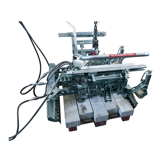
    Sicherheit 6 / 44 Sicherheitskennzeichnung VERBOTSZEICHEN Symbol Bedeutung Bestell-Nr. Größe 2904.0210 Ø 30 mm Niemals unter schwebende Last treten. Lebensgefahr! 2904.0209 Ø 50 mm 2904.0204 Ø 80 mm Quetschgefahr! Nur an Handgriffen anfassen. 2904.0367 205 x 30 mm WARNZEICHEN Symbol Bedeutung Bestell-Nr.
  • Seite 11: Persönliche Sicherheitsmaßnahmen

    Sicherheit 7 / 44 Persönliche Sicherheitsmaßnahmen • Jeder Bediener muss die Bedienungsanleitung für das Gerät mit den Sicherheitsvorschriften gelesen und verstanden haben. • Das Gerät und alle übergeordneten Geräte in/an die das Gerät eingebaut ist, dürfen nur von dafür beauftragten und qualifizierten Personen betrieben werden. •...
  • Seite 12: Hydraulik

    Sicherheit 8 / 44 2.8.2 Hydraulik Alle Hydraulikleitungen und Anschlüsse vor jedem Arbeitseinsatz auf Dichtigkeit prüfen. Defekte Teile in drucklosem Zustand von Fachpersonal austauschen lassen. Vor dem Öffnen von Hydraulikanschlüssen ist das Umfeld gründlich zu reinigen. Bei Arbeiten an der Hydraulikanlage ist auf Sauberkeit zu achten.
  • Seite 13: Sicherheit Im Verlegebetrieb

    Sicherheit 9 / 44 2.9.2 Sicherheit im Verlegebetrieb • Das Gerät nur an dessen Handgriffen in Position ziehen! • Der Bediener muss das Gerät während des gesamten Transportes bis zum Absetzen ungehindert beobachten können • Steinlagen nie außermittig aufnehmen, Kipp- und Verletzungsgefahr! •...
  • Seite 14: Ermittlung Der Greiftechnischen Qualität

    Allgemeines 10 / 44 2.9.3 Ermittlung der greiftechnischen Qualität Zum sicheren und reibungslosen Betrieb der Anlage/des Gerätes ist es unbedingt erforderlich, dass die Qualität der Steinlagen anhand der folgenden Vorgehensweise durchgeführt wird.: Die Anzahl der zu greifenden Steine wird übereinander Hauptspannungs- gestapelt, wobei die Steine auf der richtung...
  • Seite 15: Verbundsteinformen

    Allgemeines 11 / 44 Voraussetzungen bei hydraulischem Antrieb (Arbeitshydraulik des Trägergerätes): – Volumenstrom, nutzbar [l/min]: min. 25, optimal 35 bis 40, max. 80 – Betriebsdruck, nutzbar [bar]: min. 180, optimal 200, max. 320 – Rückstaudruck: max. 10 bar Mindestbetriebsgewicht Bagger : - ab ca.
  • Seite 16 Allgemeines 12 / 44 • Das Gerät darf nur für den in der Bedienungsanleitung beschriebenen bestimmungsgemäßen Einsatz, unter Einhaltung der gültigen Sicherheitsvorschriften und unter Einhaltung der dementsprechenden gesetzlichen Bestimmungen und den der Konformitätserklärung verwendet werden. • Jeder anderweitige Einsatz gilt als nicht bestimmungsgemäß und ist verboten! •...
  • Seite 17: Übersicht Und Aufbau

    10. Handgriffe zur Führung des Gerätes 4. Nebenspannweite 11. Verschiebeadapter Maschinenseitige Greifwange (Hauptspannweite) 6. Einstellbare Absetzrollen Hauptspannweite Für Steinhöhe Nebenspannweite = Tragfähigkeit WLL Eigengewicht Backenlänge L 990-1.400 580-1.470 HVZ-GENIUS-II 50-160 mm 332 kg 600-1.400 960-1.440 ** = = Öffnungsweite der Verlegezange Greifbereich (für Steinlagenabmessung) 5140.0042...
  • Seite 18: Installation

    14 / 44 Installation Mechanischer Anbau Nur Original-Probst-Zubehör verwenden, im Zweifelsfall Rücksprache mit dem Hersteller halten. Die Tragfähigkeit des Trägergerätes/Hebezeuges darf durch die Last des Gerätes, der Anbaugeräte (Drehmotor, Einstecktaschen etc.) und die zusätzliche Last der Greifgüter nicht überschritten werden! Greifgeräte müssen immer kardanisch aufgehängt werden, so dass sie in jeder Position frei auspendeln...
  • Seite 19 Installation 15 / 44 Baggeraufhängung UBA Es muss eine gesicherte Verbindung (Sicherungsschraube mit Stopp-Mutter) zwischen Drehkopf und Baggeraufhängung hergestellt werden. Baggeraufhängung (UBA) Sicherungsschraube mit Stopp-Mutter Pendelbremse Drehkopf *Einstellung der Sicherungsmutter hat Einfluss auf die Bewegungsgeschwindigkeit der Pendelbremse. 5140.0042...
  • Seite 20: Hydraulischer Anbau

    Installation 16 / 44 Hydraulischer Anbau Zum Anschluss der HVZ-GENIUS-BASIC an das Trägergerät werden zwei voneinander getrennte Hydrauliksteuerkreise benötigt. Der Anschluss der Hydraulikschläuche erfolgt am hydraulischen Drehkopf. Durch Lösen der beiden Arretierungsschrauben kann die Öffnungsweite zwischen der Bolzenaufnahme, bei Bedarf ...
  • Seite 21 Installation 17 / 44 Einstellbare Drosselventil (siehe ) in Hydraulikleitung zum Trägergerät (Bagger) für Regulierung der Drehgeschwindigkeit des Drehkopfes einbauen. Beim Anschluss der Hydraulikleitungen ist darauf zu achten, dass die Drehrichtung des Trommel, mit der der Drehrichtungsangabe (siehe ) auf dem Gehäuse über einstimmt.
  • Seite 22: Einstellung „Bypass-Ventil

    Installation 18 / 44 Einstellung „Bypass-Ventil“ Beim Einsatz von größeren Trägergeräten (Bagger), muss die Ölflussmenge zur Verlegezange durch den Einbau eines sogenannten „Bypass-Ventil“ erhöht werden. Um ein störungsfreies Arbeiten mit der Verlegezange zu gewährleisten. 5140.0042...
  • Seite 23: Einstellungen

    Einstellungen 19 / 44 Einstellungen Allgemein Alle Einstellarbeiten dürfen nur bei stillgelegtem Gerät vorgenommen werden! Vorsicht bei allen Einstellarbeiten besteht Verletzungsgefahr der Hände! 5.1.1 Greiftiefeneinstellung 5.1.1.1 Planumseite Bei extrem großen Steinlagen empfiehlt es sich die Greiftiefeneinstellung (Planumseite) ist so einzustellen, dass ⅓...
  • Seite 24 Einstellungen 20 / 44 Federriegel um 180 verdrehen und in Kerbe einrasten. Abstand ca. auf 100mm -150 mm Mitte Greiftiefeneinstellung Greiftiefeneinstellung entsprechend verschieben u. von der Außenkante der Steinlage einstellen (siehe Federriegel wieder um 180 verdrehen und einrasten. Einstellaufkleber am Gerät). Bild 5 Bild 6 100-150 mm...
  • Seite 25: Maschinenseite

    Einstellungen 21 / 44 5.1.1.2 Maschinenseite Greiftiefeneinstellung (Maschinenseite) ist so einzustellen, Bei extrem großen Steinlagen empfiehlt es sich die Greiftiefeneinstellung etwas niedriger einzustellen, so dass die ½ dass die Stahllamellen sich auf der der Steinlage (siehe Stahllamellen im untersten Bereich der Steinlage greifen. Ansonsten Bild 8) befinden.
  • Seite 26: Einstellung Absetzrollen

    Einstellungen 22 / 44 5.1.2 Einstellung Absetzrollen Zum Einstellen der Absetzrollen, Kurbel nach oben Durch Drehen an der Kurbel Höhe der Absetzrollen schwenken. verändern. Bild 12 Bild 11 Höhe der beider Absetzrollen genau gleich einstellen. Abstand zwischen Lamellen zur Steinlangenunterkante ungefähr 50 mm (siehe Darstellung A) Kurbel wieder nach unten schwenken und einrasten.
  • Seite 27: Einstellung Hauptspannung

    Einstellungen 23 / 44 5.1.3 Einstellung Hauptspannung Einstellung „C“ der Hauptspannung laut Einstellaufkleber Hauptspannung auf Position ziehen. am Gerät (Maschinenseite) entsprechend der Federriegel wieder um 180 verdrehen und einrasten Steinlagenlänge. Federriegel () um 180 verdrehen und in Kerbe einrasten Bild 14 Bild 15 Einstellaufkleber 5140.0042...
  • Seite 28 Einstellungen 24 / 44 Einstellung „A“ und „D“ Hauptspannung laut Klappsplint am Bolzen entnehmen. Einstellaufkleber am Gerät (Planumseite) entsprechend der Steinlagenlänge einstellen. Bild 17 Bild 16 Einstellaufkleber 5140.0042...
  • Seite 29 Einstellungen 25 / 44 Hauptspannung auf entsprechende Bohrungsposition ziehen, Bolzen wieder Einstecken (siehe Bild 15), Bolzen mit Klappsplint sichern (siehe Bild 17) und Federriegel um 180° (siehe Bild 14) verdrehen und in entsprechende Bohrung Bolzen entnehmen. einrasten lassen (siehe Einstellaufkleber). Bild 19 Bild 18 Das Gerät (HVZ-GENIUS) ist optimal eingestellt, wenn beim Greifvorgang bei geöffneter Zange, die Stahl-Lamellen...
  • Seite 30: Einstellung Feder-Stahllamellen

    Einstellungen 26 / 44 5.1.4 Einstellung Feder-Stahllamellen Die Stahllamellen sollten nicht seitlich über die Steinkontur hervorstehen, da sie sonst beim Ablegevorgang die bereits verlegten Steine erfassen und diese ins Planum drücken können. Je nach Länge des Paketes seitlich überstehende Lamellen abnehmen oder durch 1,5-Fache Lamellen oder Halblamellen ersetzen.
  • Seite 31: Veränderung Der Backenbreite

    Einstellungen 27 / 44 5.1.5 Veränderung der Backenbreite Zum optimalen Greifen der Steinlagen, besteht die Möglichkeit die Backenbreite entsprechend zu verändern. Grund: da oftmals die jeweils außen liegenden Feder- Stahllamellen (Bild 21.1) beim Greifvorgang an der Steinlage außen etwas überstehen und somit das Anlegen an eine bereits verlegte Steinlage eventuell erschweren.
  • Seite 32: Greifwangen-Verbreiterung

    Einstellungen 28 / 44 5.1.7 Greifwangen-Verbreiterung Greifwangen-Verbreiterung der Hauptspannung Greifwangen-Verbreiterung der Hauptspannung (Planumseite) je nach Steinlagenbreite entfernen, oder (Maschineseite) je nach Steinlagenbreite entfernen, oder anbauen. anbauen. Dazu Schraube „D“ entfernen. Stellschraube „B“ entfernen, um Verbreiterung zu Stellschraube „E“ für Schrägstellung/Vorspannung der entfernen.
  • Seite 33: Einstellung Nebenspannweite

    Einstellungen 29 / 44 5.1.8 Einstellung Nebenspannweite Schraubensicherung an Nebenspannung rechts u. links am Klemmschraube der Nebenspannung mit Steckschlüssel Gerät (auf Seite der Hauptspannung) gezeigt hochklappen. öffnen. Schraubensicherung wieder schließen. Bild 24 Bild 25 Einstellung Nebenspannung auf Steinlagebreite Nebenspannung mit Steckschlüssel nach Skala einstellen. Schraubensicherung hochklappen.
  • Seite 34: Greiftiefeneinstellung Nebenspannung

    Einstellungen 30 / 44 Einstellwert (Steinlagenlänge) über Skala muss an roter Klemmschraube der Nebenspannung mit Steckschlüssel Markierung sein (siehe Pfeil). Nebenspannung rechts u. links wieder schließen und auf gleichen Wert einstellen. Schraubensicherung wieder herunterklappen. Skala Bild 28 Bild 29 5.1.9 Greiftiefeneinstellung Nebenspannung ...
  • Seite 35: Einstellung Positionieradapter

    Einstellungen 31 / 44 Bild B Bild C Bild A bei Steindicke 6 cm bei Steindicke 8 cm bei Steindicke 10 cm Greiftiefeneinstellung in Stellung 1 Greiftiefeneinstellung in Stellung 2 Greiftiefeneinstellung in Stellung 3 montieren. montieren. montieren. 5.1.10 Einstellung Positionieradapter Die überstehende Länge der Positionieradapter zwischen Halfeneisen und Schraubenkopf (Vorsprungsmaß) beim abgebildeten Beispiel beträgt bei Halbsteinverband 20 cm dividiert durch 2 = 10 cm.
  • Seite 36: Gewichtsausgleich Einstellen

    Einstellungen 32 / 44 Hauptspannungsrichtung Bild 32 Bild 33 5.1.11 Gewichtsausgleich einstellen Nach erfolgter Einstellung der Haupt- u. Nebenspannung am Gerät ist darauf zu achten, dass es waagrecht zur Arbeitsfläche ausgerichtet ist, gegebenenfalls leicht geneigt zur Maschinenseite (Absetzrollen). Als Orientierung: der mittlere Steckbolzen (B) sollte sich in etwa in der Mitte der Steinlage befinden (gesehen aus Sicht der Nebenspannung).
  • Seite 37 Einstellungen 33 / 44 Verletzungsgefahr der Hände! Bild 34 5140.0042...
  • Seite 38: Bedienung

    Bedienung 34 / 44 Bedienung Niemals (mit und ohne Steinlage) bei geschlossener Nebenspannung die Hauptspannung schließen. Da ansonsten die Gefahr besteht, dass die Hauptspannbacken gegen die Halfeneisen (der Nebenspannung) drücken und dadurch die Greifwangen der Hauptspannung verbogen/beschädigt werden können. Wird der Auslegerarm des Trägergerätes (Baggers) mit gegriffener Steinlage zu weit nach außen bewegt, besteht Kippgefahr des Trägergerätes (Baggers) - bedingt durch das Eigengewicht der Verlegezange und das Gewicht der Steinlage.
  • Seite 39: Programme

    Bedienung 35 / 44 • Bei Einsatz am Bagger: Machen Sie sich mit den Bedienelementen des Trägergerätes für die beiden Steuerkreise für Klammerbetätigung und Drehkopfbetätigung vertraut. Prägen Sie sich insbesondere ein, welche Hebelfunktion ein Öffnen der Klammer (meist Betätigung des hydraulischen Steuerhebels vom Bediener weg) bewirkt, damit Sie nicht aus Versehen diese Funktion bei angehobener HVZ-GENIUS mit gegriffener Steinlage betätigen und so die Steinlage aus der Klammer herausfallen Unfallgefahr! lassen.
  • Seite 40: Ablauf Des Verlege-Zyklus

    Bedienung 36 / 44 OHNE ADV MIT ADV • Durch die Einstellung der Greifweite der Nebenspannung (Einstellung P) wird sichergestellt, dass die Einzelsteine in Greifrichtung der Nebenspannung nicht knirsch aneinandergepresst liegen, sondern einen geringen, zusätzlichen Fugenabstand in Richtung der Nebenspannung aufweisen. Nach dem Ablegevorgang dürfen diese zusätzlichen, geringen Fugenabstände auf keinen Fall durch zusammenklopfen mit dem Gummihammer von der Planumseite her beseitigt werden.
  • Seite 41 Bedienung 37 / 44 • Die Klammer über die zu greifende Steinlage schwenken • Mittels des hydraulischen Drehkopfes die Klammer so drehen, dass sie über die zu greifende Steinlage abgesenkt werden kann. • Die Klammer so verschwenken, dass die Stahllamellen der anlegeseitigen Hauptspannbacke nach Möglichkeit die Steine berühren.
  • Seite 42: Allgemeine Hinweise Zur Normgerechten Verlegung

    Bedienung 38 / 44 Nun ist der Verlegezyklus abgeschlossen, die Klammer ist bereit zur Aufnahme der nächsten zu verlegenden Steinlage. Der Ablauf der Verlegezyklus ist erst dann komplett beendet, wenn ADV u. die rote Markierung (siehe Pfeil Bild 2) an der Geräterückseite/ wieder komplett sichtbar ist.
  • Seite 43 Bedienung 39 / 44 • An eventuellen Trennstellen von alter Handverlegung zu maschineller Verlegung am besten komplett neuen Anfang machen, da Hand- und Maschinenverlegung meist unterschiedliche Fugen aufweisen. • Laufend überprüfen, ob die Rechtwinkligkeit, der Fugenverlauf und das Rastermaß des Belages noch stimmen. Manchmal sind spätere Korrekturen unmöglich oder verschlingen enorme Zeit zur Nacharbeit.
  • Seite 44: Wartung Und Pflege

    Wartung und Pflege 40 / 44 Wartung und Pflege Wartung Um eine einwandfreie Funktion, Betriebssicherheit und Lebensdauer des Gerätes zu gewährleisten, sind die in der Tabelle aufgeführten Wartungsarbeiten nach Ablauf der angegebenen Fristen durchzuführen. Es dürfen nur Original-Ersatzteile verwendet werden, ansonsten erlischt die Gewährleistung. Alle Arbeiten dürfen nur im drucklosen, stromlosen und beim stillgelegten Zustand des Gerätes erfolgen! Bei allen Arbeiten muss sichergestellt sein, dass sich das Gerät nicht unbeabsichtigt schließen kann.
  • Seite 45: Hydraulik

    Wartung und Pflege 41 / 44 Schmiernippel Alle Schmiernippel (siehe ) an der Schmiernippel (siehe ) am Hubzylinder der Seitenspannung rechts u. links am Gerät 1x Seitenspannung rechts u. links am Gerät 1x wöchentlich mit Fettpresse abschmieren. wöchentlich mit Fettpresse abschmieren. Alle Bolzen und bewegliche Teile 1x wöchentlich fetten.
  • Seite 46: Störungssuche

    Wartung und Pflege 42 / 44 Störungssuche STÖRUNG URSACHE BEHEBUNG • • Steinlage bricht nach unten aus Hauptspannung ist falsch Einstellung nach Einstellaufkleber eingestellt (200 mm Hub) überprüfen • • Steinlage ist extrem groß Greiftiefe etwas tiefer einstellen, dass Stahllamellen im unteren Bereich der Steinlage greifen.
  • Seite 47: Reparaturen

    • Die dementsprechenden gesetzlichen Bestimmungen u. die der Konformitätserklärung sind zu beachten! • Die Durchführung der Sachkundigenprüfung kann auch durch den Hersteller Probst GmbH erfolgen. Kontaktieren Sie uns unter: service@probst-handling.com • Wir empfehlen, nach durchgeführter Prüfung und Mängelbeseitigung des Gerätes die Prüfplakette „Sachkundigenprüfung / Expert inspection“...
  • Seite 48: Hinweis Zum Typenschild

    Kettenzug, Gabelstapler, Bagger...) mit zu berücksichtigen. Beispiel: Hinweis zur Vermietung/Verleihung von PROBST-Geräten Bei jeder Verleihung/Vermietung von PROBST-Geräten muss unbedingt die dazu gehörige Original Betriebsanleitung mitgeliefert werden (bei Abweichung der Sprache des jeweiligen Benutzerlandes, ist zusätzlich die jeweilige Übersetzung der Original Betriebsanleitung mit zuliefern)!
  • Seite 49: Wartungsnachweis

    (durch eine autorisierte Fachwerkstatt)! Nach jeder erfolgten Durchführung eines Wartungsintervalls muss unverzüglich dieser Wartungsnachweis (mit Unterschrift u. Stempel) an uns übermittelt werden 1). 1) per E-Mail an: service@probst-handling.com / per Fax oder Post Betreiber: _ _ _ _ _ _ _ _ _ _ _ _ _ _ _ _ _ Gerätetyp:...
  • Seite 51 Operating Instructions Translation of original operating instructions Hydraulic Installation Clamp HVZ-GENIUS-II HVZ-GENIUS-II 5140.0042...
  • Seite 52 Contents 2 / 45 Contents EC-Declaration of Conformity ..........................4 Safety ..................................5 Definition skilled worker / specialist ......................5 Explanation of basic concepts ........................5 Safety symbols ..............................5 Safety Marking ..............................6 Personal safety requirements ........................7 Protective equipment............................. 7 Accident prevention ............................
  • Seite 53 3 / 45 Maintenance ..............................41 7.1.1 Mechanical ..............................41 7.1.2 Hydraulic ..............................42 Trouble shooting ............................43 Repairs ................................44 Safety procedures ............................44 Hints to the type plate ..........................45 Hints to the renting/leasing of PROBST devices ..................45 5140.0042...
  • Seite 54: Ec-Declaration Of Conformity

    Safety of machinery - safety distances to prevent hazard zones being reached by upper and lower limbs (ISO 13857:2008) Authorized person for EC-documentation: Name: J. Holderied Address: Probst GmbH; Gottlieb-Daimler-Straße 6; 71729 Erdmannhausen, Germany Signature, information to the subscriber: Erdmannhausen, 20.05.2019................
  • Seite 55: Safety

    Safety 5 / 45 Safety Definition skilled worker / specialist Only skilled workers or specialists are allowed to carry out the installation-, maintenance-, and repair work on this device! • Skilled workers or specialists must have for the following points (if it applies for for mechanic this device), the necessary professional knowledge.
  • Seite 56: Safety Marking

    Safety 6 / 45 Safety Marking PROHIBITION SIGN Symbol Meaning Order-No. Size 2904.0210 Ø 30 mm It is not allowed to stand under hanging loads. Danger to life! 2904.0209 Ø 50 mm 2904.0204 Ø 80 mm Danger of squeezing the hands! Touch only at handles. 2904.0367 205 x 30 mm WARNING SIGN...
  • Seite 57: Personal Safety Requirements

    Safety 7 / 45 Requirements for hydraulic carrier (excavator) : 2904.0498 58x36 mm Volumetric flow (l/min), usable min. 25, optimal 35 – 40, max. 80 Working pressure (bar), usable min. 180, optimal 200, max. 320 Minimum excavator operating weight: from approx. 3,5 t Personal safety requirements Each operator must have read and understood the operating instructions (and all safety instructions).
  • Seite 58: Function Control

    Safety 8 / 45 Function Control 2.8.1 General • Before every usage of the device check the functions and the working condition. • Maintenance and lubrication are only permitted when device is shut down! • Do not use the device, until all faults which can cause safety hazards are removed. •...
  • Seite 59: Safety At Installation Work

    Safety 9 / 45 2.9.2 Safety at installation work • The manual guiding of is only allowed for devices with handles! • The load must always be in the range of vision of the operator, during the transporting and laying operation.
  • Seite 60: Check On The Gripping Quality Of Certain Layers Of Paving Stones

    General 10 / 45 2.9.3 Check on the gripping quality of certain layers of paving stones For the secure function of the automatic cuber/the device the gripping quality of certain layers of paving stones has to be checked as follows: Take the number of blocks you want to grip.
  • Seite 61: Stone Formations

    General 11 / 45 Requirements for hydraulic operation (operating hydraulics of the carrier): HVZ-GENIUS: – Volumetric flow (l/min), usable min. 25, optimal 35 – 40, max. 80 – Working pressure (bar), usable min. 180, optimal 200, max. 320 – Backflow pressure: max. 10 bar Minimum excavator operating weight: –...
  • Seite 62 General 12 / 45 • The device is only designed for the use specified in this documentation. • Every other use is not authorized and is forbidden! • All relevant safety regulations, corresponding legal regulations, especially regulations of the declaration of conformity, and additional local health and safety regulations must be observed.
  • Seite 63: Survey And Construction

    Type Side Gripping Width L Width (WLL) 990-1.400 580-1.470 (39“-55“) (22¾“-58“) 50-160 mm 332 kg (730 HVZ-GENIUS-II 400 kg (880 lbs) (2 - 6¾“) lbs) 600-1.400 960-1.440 (23½“--55“) (37¾“-55“) ** = = Opening width of the hydraulic clamp Gripping range (for stone layer dimensions)
  • Seite 64: Installation

    Installation 14 / 45 Installation Mechanical connection Use only original accessories, in case of doubt consult the manufacturer. Take care that the carrying capacity / working load limit (WLL) of the lifting device/carrier is not exceeded, through the load of the device, the attaching devices (turning device, fork sleeves etc.) and the additional load of the gripping goods! Gripping devices always have to be gimballed, so they can swing freely in any position.
  • Seite 65 Installation 15 / 45 Excavator-suspension UBA Make a secure connection (locking bolt with nut and a additional lock nut) between the rotating head and the excavator suspension. Excavator suspension (UBA) Safety bolt with locking ring (+ locknut) Grab swing brake Rotating head * The adjustment of the nut with locknut takes effect of the speed movement of the grab swing brake.
  • Seite 66: Hydraulical Connection

    Installation 16 / 45 Hydraulical connection Two separate hydraulic circuit are required to connect the HVZ-GENIUS to the support frame The connection of the hydraulic hoses takes place on the hydraulic rotator.  The opening width between the bolt sockets can be adjusted ( ) by loosening of the locking screws.
  • Seite 67 Installation 17 / 45 Install the adjustable throttle valve (see ). at the hydraulic line (to the support frame (excavator)). The throttle valve regulates the rotational speed of the rotating head When connecting the hydraulic lines, look after the rotating direction of the drum, that it is identical to the rotating direction at the casting (see ).
  • Seite 68: Adjustment „Bypass- Valve

    Installation 18 / 45 Adjustment „Bypass- Valve“ When using larger support frames (excavator), the oil flow to the installation clamp must be increased by installing a so- called "by-pass valve". To ensure a trouble-free operation with the installation clamp. 5140.0042...
  • Seite 69: Adjustments

    Adjustments 19 / 45 Adjustments General For all adjustments the device must be completely shut down! Caution with all adjustments exists danger of injury the hands! 5.1.1 Adjusting the gripping depth 5.1.1.1 Facing bedding sand With extremely large stone layers it recommends to adjust the Adjust the gripping depth (laying side) so, that the steel- ⅓...
  • Seite 70 Adjustments 20 / 45 Pull the spring bolt upwards, rotate around 180° and Adjust the gripping depth distance approx. on 100mm - lock in position (in nick). 150 mm from the middle of the gripping depth to the outside edge of the stone layer (see stickers at the Adjust gripping depth and rotate the spring bolt again device).
  • Seite 71: Machine Side

    Adjustments 21 / 45 5.1.1.2 Machine Side Adjust the gripping depth (machine side) so, that the With extremely large stone layers it recommends to adjust the gripping depth a little lower, so that the steel-lamellas grip in ½ steel-lamellas are gripping in the of the stone layer the lowest range of the stone layer.
  • Seite 72: Height Adjustment Of The Rollers

    Adjustments 22 / 45 5.1.2 Height adjustment of the rollers Swing crank upwards to adjust the height of the rollers. By Rotating at the crank change the height of the rollers. Fig. 11 Fig. 12 Adjust the height of both rollers identically. Distance between the steel lamellas to the lower edge of the stone layer ~ 50 mm (see picture A ) Swing crank downwards and secure it in the same...
  • Seite 73: Adjustment Main Clamping

    Adjustments 23 / 45 5.1.3 Adjustment main clamping Adjust adjusting „C“ at the main gripping corresponding Pull main gripping in the corresponding position. to the length of the stone layer → see sticker at the Rotate the spring bolt again around 180° and lock in device (machine side).
  • Seite 74 Adjustments 24 / 45 Adjust the adjusting „A“ und „D“ at the main gripping Remove safety clip at the bolt. corresponding to the length of the stone layer → see sticker at the device (laying side). Fig. 17 Fig. 16 Adjustment sticker 5140.0042...
  • Seite 75 Adjustments 25 / 45 Pull main gripping in the corresponding borehole position (see fig. 19) and insert bolt again (see fig. 15). Secure bolt with safety clip (as shown in fig.17) again. Rotate the spring bolt again around 180° (as shown in Remove bolt.
  • Seite 76 Adjustments 26 / 45 1.1 Adjustment of the steel-lamellas The steel-lamellas should not stitch out sideways over the contur of the laying cluster, because they could hit the already laid blocks when laying a new cluster into an edge. Depending on the length of a pack, the lamellas which are stitching over, should be replaced by the 1.5 lamella or the half lamella.
  • Seite 77: Extension Of The Gripper Width

    Adjustments 27 / 45 5.1.4 Extension of the gripper width For optimum gripping of the stone layers, it is possible to change the gripper width (of the main clamping) Reason: because often the outer feather-steel-lamellas (Fig 21.1) overlaps outside of the stone layer during the gripping process and thus complicate the direct positioning to an already laid stone layer eventually.
  • Seite 78: Gripper Widening

    Adjustments 28 / 45 5.1.6 Gripper Widening Remove or mount the gripper widening at the main Remove or mount the gripper widening at the main gripping (laying side) corresponding to the breadth of gripping (machine side) corresponding to the breadth the stone layer.
  • Seite 79: Adjustment Side Gripping

    Adjustments 29 / 45 5.1.7 Adjustment side gripping Lift up both screw locking devices (see arrow) at side Open clamping screw with a socket spanner. clamping (see on the left and on the right at the main Turn down screw locking devices again. gripping side of the device).
  • Seite 80 Adjustments 30 / 45 The setting dimension (stone layer length) on scale Close clamping screw of the side gripping with a socket must be at the red marking (see arrow). spanner. Adjust the setting dimension identically on both sides. Turn down screw locking devices again. Scale Fig.
  • Seite 81 Adjustments 31 / 45 Fig. B Fig. C Fig. A • paver thickness 6 cm paver thickness 10 cm paver thickness 8 cm depth-adjustment in position 1 depth-adjustment in position 3 depth-adjustment in position 2 • Opening width side direction The HVZ-GENIUS with its powerful side clamping action, is capable to shift clamping not dentated layers of pavers which are palletized in cross bond into the...
  • Seite 82: Setting Positioning Adapters

    Adjustments 32 / 45 • The distance between the head of the adapter and the C-profile is usually Setting positioning adapters half the length of one block, when half bond is required. • In the example shown, length of the paver is 20 cm, divided by 2 = 10 cm.
  • Seite 83 Adjustments 33 / 45 Remove locking pin (A) from plug bolt (B) Pull out the plug bolt (B) (see arrow). Place the rotating head at the corresponding position (at the HVZ-GENIUS) – plug in the plug bolt (B) again und secure it with locking pin (A).
  • Seite 84: Operation

    Operation 34 / 45 Operation Never close (with or without a stone layer) the main clamping when the side clamping is closed. Otherwise, there is a risk that the main clamping jaws can be pressed against the halfen rails (of the side clamping) and thereby the grippers of the side clamping can be bent/damaged.
  • Seite 85: Programms

    Operation 35 / 45 Actuate the control levers slowly, if possible in the idle gas of the carrier. • Operating the HVZ-GENIUS with an excavator: Make yourself familiar with the operating elements for the both hydraulic circuits (main / side gripping direction).
  • Seite 86: Indications For Concrete Paver Installation, Complying With The Standards

    Operation 36 / 45 Indications for concrete paver installation, complying with the standards • It is assumed that the concrete paving stone installation units (layers of pavers), which are to be laid, comply with the requirements allowing a uniform laying pattern, complying with the standards. •...
  • Seite 87: Operating Procedure Of Laying Cycle

    Operation 37 / 45 Operating procedure of laying cycle General is it the drivers obligation (of the support vehicle) to have at every time the complete working area of the support frame and the attachment in his field of view. He must ensure, that in the danger zone are either persons nor objects •...
  • Seite 88 Operation 38 / 45 • Position the HVZ-GENIUS over the stone layer, which shall be gripped. • Turn the HVZ-GENIUS in such a way by means of the hydraulic rotator that it can be lowered over the stone layer which can be gripped. •...
  • Seite 89: General Hints For Laying According To Standards

    Operation 39 / 45 Now the lying cycle is finished, the device is ready for the admission of the next stone layer which can be installed. The laying cycle is finally finished, when the ADV-bar () and the red marking (see fig.2) is complete visible. red marking Fig.
  • Seite 90: 6.6 General Laying-Hints

    Operation 40 / 45 6.6 General laying-hints: • To optimize the high degree of mechanization in the mechanical paver laying it is necessary t optimize the boundary conditions. Because the laying process consists in majority of transportation and the process of paving is the smaller part it is evident to optimize the transportation on the building ground.
  • Seite 91: Maintenance And Care

    Maintenance and care 41 / 45 Maintenance and care Maintenance To ensure the correct function, safety and service life of the device the following points must be executed in the maintenance interval. Used only original spare parts, otherwise the warranty expires. All operations may only be made in unpressurised, electro less and closed state of the device! For all operations you have to make sure, that the device will not close unintended.
  • Seite 92: Hydraulic

    Maintenance and care 42 / 45 Grease all bolts and movable parts 1x per week. 7.1.2 Hydraulic Service interval Maintenance work First inspection after • Control and tighten all hydraulic thread joints and connection. 25 operating hours (The implementation is only allowed by an expert). All 50 operating hours •...
  • Seite 93: Trouble Shooting

    Maintenance and care 43 / 45 Trouble shooting ERROR CAUSE REPAIR • • Stone layer breaks out (downward) Main clamping is wrong Check the adjustments according adjusted (stroke 200 mm) to the adjustment sticker • • Stone layer is too large Adjust the gripping depth a little lower, so that the steel lamellas grip in the lower range of the...
  • Seite 94: Repairs

    • The corresponding legal regulations and the regulations of the declaration of conformity must be observed! • The expert inspection can also be done by the manufacturer Probst GmbH. Contact us at: service@probst-handling.com • We recommend affixing the inspection sticker "„Sachkundigenprüfung / Expert inspection" in a clearly visible place (order no.: 2904.0056+Tüv sticker with year number) after the inspection has been done.
  • Seite 95: Hints To The Type Plate

    Example: Hints to the renting/leasing of PROBST devices With every renting/leasing of PROBST devices the original operating instructions must be included unconditionally (in deviation of the users country's language, the respective translations of the original operating instructions must be delivered additionally)!
  • Seite 96 After each completed performance of a maintenance interval the included form must be fill out, stamped, signed and send back to us immediately 1) via e-mail to service@probst-handling.com / via fax or post Operator: _ _ _ _ _ _ _ _ _ _ _ _ _ _ _ _ _...
  • Seite 97 Paketmaß 600 - 1400 960 - 1440 stone layer dimension 23,5" - 55" stone layer dimension 37,8" - 56,5" (Main Gripping) (Side Gripping) Tragfähigkeit / Working Load Limit WLL: kg / Eigengewicht / Dead Weight: kg / 796,4 Product Name: Hydraulic installation clamp HVZ-GENIUS II ©...
  • Seite 98 20100015 21050134 Detail A (1 : 5) 20100017 34010099 34010100 20000008 20000011 33100061 41401118 Liste 20100016 21340014 20100017 41900159 20080015 20400002 20020045 33100061 41400602 20540036 41400709 20000069 21710010 30320064 41401100 20100049 20400003 41401117 Blatt 14 20100016 Blatt 15 20000017 33501834 41401127 Blatt 3 41400601...
  • Seite 99 41401106 20000025 21720001 34010097 21720001 © all rights reserved conform to ISO 16016 20100017 20100015 31600008 21700011 30360002 Datum Name Benennung fester Backen für Erst. 13.2.2019 R.Hoffmann HVZ - Genius II komplett Gepr. 15.4.2019 R.Hoffmann Artikelnummer/Zeichnungsnummer Blatt E51400042 Zust. Urspr. Ers.
  • Seite 100 20100017 21720001 © all rights reserved conform to ISO 16016 Datum Name Benennung fester Backen für Erst. 13.2.2019 R.Hoffmann 34010097 21720001 20000025 41401107 HVZ - Genius II komplett Gepr. 15.4.2019 R.Hoffmann Artikelnummer/Zeichnungsnummer Blatt E51400042 Zust. Urspr. Ers. f. Ers. d.
  • Seite 101 20040004 20100015 41401096 30330061 20400002 20400002 30330061 20100015 20000010 20040004 20400002 21400042 20100015 21400042 21400025 30330084 20000010 22160103 41401095 20440004 33504606 41401091 22200090 20100015 21070131 20100004 20530006 41401129 20000267 21400042 Blatt 5 20100015 20100006 30330060 20400002 33504957 20000009 20550012 © all rights reserved conform to ISO 16016 20400002 Datum Name...
  • Seite 102 20140005 20400005 41400844 bei Montage mit 20140005 abgebohrt © all rights reserved conform to ISO 16016 Datum Name Benennung fester Backen für Erst. 13.2.2019 R.Hoffmann HVZ - Genius II komplett Gepr. 15.4.2019 R.Hoffmann Artikelnummer/Zeichnungsnummer Blatt E51400042 Zust. Urspr. Ers. f. Ers.
  • Seite 103 20000018 20400003 20100016 41400487 Blatt 7 20100023 20400031 21710011 20400031 20000371 41401119 21800001 20440006 20000023 © all rights reserved conform to ISO 16016 Datum Name Benennung fester Backen für Erst. 13.2.2019 R.Hoffmann HVZ - Genius II komplett Gepr. 15.4.2019 R.Hoffmann Artikelnummer/Zeichnungsnummer Blatt E51400042...
  • Seite 104 20000004 20400001 21600024 26800009 20400001 20400004 20100014 41401063 26800006 © all rights reserved conform to ISO 16016 Datum Name Benennung fester Backen für Erst. 13.2.2019 R.Hoffmann HVZ - Genius II komplett Gepr. 15.4.2019 R.Hoffmann Artikelnummer/Zeichnungsnummer Blatt E51400042 Zust. Urspr. Ers. f. Ers.
  • Seite 105 41401110 33100291 20000275 20400004 20100017 20400004 41401108 © all rights reserved conform to ISO 16016 Datum Name Benennung fester Backen für Erst. 13.2.2019 R.Hoffmann HVZ - Genius II komplett Gepr. 15.4.2019 R.Hoffmann Artikelnummer/Zeichnungsnummer Blatt E51400042 Zust. Urspr. Ers. f. Ers. d.
  • Seite 106 41401110 33100291 20000275 20400004 20100017 20400004 41401109 © all rights reserved conform to ISO 16016 Datum Name Benennung fester Backen für Erst. 13.2.2019 R.Hoffmann HVZ - Genius II komplett Gepr. 15.4.2019 R.Hoffmann Artikelnummer/Zeichnungsnummer Blatt E51400042 Zust. Urspr. Ers. f. Ers. d.
  • Seite 107 41400501 20100017 20000036 20000025 20100006 21720001 34010097 21720001 41400502 20100017 20000065 20000025 © all rights reserved conform to ISO 16016 Datum Name Benennung fester Backen für Erst. 13.2.2019 R.Hoffmann HVZ - Genius II komplett Gepr. 15.4.2019 R.Hoffmann Artikelnummer/Zeichnungsnummer Blatt E51400042 Zust.
  • Seite 108 20000024 41400523 33501979 20100006 20000141 41400524 20100017 Blatt 17 20000090 20100017 41400503 21720001 34010097 21720001 20000025 © all rights reserved conform to ISO 16016 Datum Name Benennung fester Backen für Erst. 13.2.2019 R.Hoffmann HVZ - Genius II komplett Gepr. 15.4.2019 R.Hoffmann Artikelnummer/Zeichnungsnummer Blatt...
  • Seite 109 20100022 33502650 33502325 20020059 33502432 33502431 20020059 33502329 33502331 33502429 33502430 33502651 33502331 20100022 41400507 Blatt 13 © all rights reserved conform to ISO 16016 Datum Name Benennung fester Backen für Erst. 13.2.2019 R.Hoffmann 21750006 HVZ - Genius II komplett Gepr.
  • Seite 110 20200026 20020077 33210005 33503410 33210001 24210039 21200009 21750015 20520006 33210002 33210004 20020086 33210003 21400023 21570044 22400004 © all rights reserved conform to ISO 16016 Datum Name Benennung fester Backen für Erst. 13.2.2019 R.Hoffmann HVZ - Genius II komplett Gepr. 15.4.2019 R.Hoffmann Artikelnummer/Zeichnungsnummer Blatt...
  • Seite 111 33506648 20100015 20400002 20000009 20400002 36400342 von innen angeschraubt © all rights reserved conform to ISO 16016 Datum Name Benennung fester Backen für Erst. 13.2.2019 R.Hoffmann HVZ - Genius II komplett Gepr. 15.4.2019 R.Hoffmann Artikelnummer/Zeichnungsnummer Blatt E51400042 Zust. Urspr. Ers. f. Ers.
  • Seite 112 20000150 33100271 20100014 20400004 33506711 41401114 41400519 41401115 © all rights reserved conform to ISO 16016 Datum Name Benennung fester Backen für Erst. 13.2.2019 R.Hoffmann HVZ - Genius II komplett Gepr. 15.4.2019 R.Hoffmann Artikelnummer/Zeichnungsnummer Blatt E51400042 Zust. Urspr. Ers. f. Ers.
  • Seite 113 33100271 20100014 20400004 20000150 33506711 41401113 41400519 41401115 © all rights reserved conform to ISO 16016 Datum Name Benennung fester Backen für Erst. 13.2.2019 R.Hoffmann HVZ - Genius II komplett Gepr. 15.4.2019 R.Hoffmann Artikelnummer/Zeichnungsnummer Blatt E51400042 Zust. Urspr. Ers. f. Ers.
  • Seite 114 20530005 20100008 20440008 20100065 20250070 © all rights reserved conform to ISO 16016 Datum Name Benennung fester Backen für Erst. 13.2.2019 R.Hoffmann HVZ - Genius II komplett Gepr. 15.4.2019 R.Hoffmann Artikelnummer/Zeichnungsnummer Blatt E51400042 Zust. Urspr. Ers. f. Ers. d.
  • Seite 115 22160117 24100149 22500026 22120003 32160005 22120007 24100149 24100146 22160045 22140437 22120003 22140423 22140437 22140418 22160117 22140423 22120007 22120003 22140418 © all rights reserved conform to ISO 16016 Datum Name Benennung Hydraulik-Schaltplan für HVZ - Genius II Erst. 29.1.2019 R.Hoffmann Gepr. 15.4.2019 R.Hoffmann 22140465...
  • Seite 116 A51400042 HVZ-GENIUS-II 29040783 29040498 29040209 auf beiden Seiten/ on both sides 29040221 Auf beiden Seiten/ on both sides 29040665 29040220 Fgst.-Nr. 29040056 chassis number 29040221 29040814 29040367 P 12.06.2019_V1 1 / 1 Einige der Abbildungen sind möglicherweise optionales Zubehör des Gerätes/Some of pictures may be optional equipment of the device.

Inhaltsverzeichnis