Herunterladen Inhalt Inhalt Diese Seite drucken
Inhaltsverzeichnis

Werbung

Verfügbare Sprachen

Verfügbare Sprachen

/ Perfect Charging /
Perfect Welding
Prüfvorrichtung Robacta
Robacta Testing System
Dispositif de contrôle Robacta
Przyrząd kontrolny Robacta
42,0410,0927
Fronius prints on elemental chlorine free paper (ECF) sourced from certified sustainable forests (FSC).
/ Solar Energy
006-20082019
Bedienungsanleitung
Systemerweiterung
Operating Instructions
System extension
Instructions de service
Extension système
Instrukcja obsługi
Rozbudowa systemu

Werbung

Inhaltsverzeichnis
loading

Inhaltszusammenfassung für Fronius Robacta series

  • Seite 1 Systemerweiterung Operating Instructions Robacta Testing System System extension Instructions de service Dispositif de contrôle Robacta Extension système Instrukcja obsługi Przyrząd kontrolny Robacta Rozbudowa systemu 42,0410,0927 006-20082019 Fronius prints on elemental chlorine free paper (ECF) sourced from certified sustainable forests (FSC).
  • Seite 3: Inhaltsverzeichnis

    Inhaltsverzeichnis Allgemeines ............................... Allgemeines ............................Prüfvorrichtung kalibrieren ........................Benötigtes Werkzeug..........................Optionen ............................... Lieferumfang .............................. Prüfvorrichtung Robacta W........................Prüfvorrichtung Robacta G ........................Prüfvorrichtung Robacta Twin....................... Prüfvorrichtung Robacta Twin Professional..................Prüfvorrichtung Robacta Gesamtsystem ....................Prüfvorrichtung Robacta Gesamtsystem Twin..................Prüfvorrichtung Robacta W / V ......................Prüfvorrichtung Robacta G / V ......................
  • Seite 4 Schweißbrenner prüfen......................... Prüfvorrichtung Robacta Compact Pro Twin - kundenspezifische Twin Roboter-Schweißbrenner prüfen Allgemeines ............................Schweißbrenner mit PA-Ausrichtung prüfen..................Schweißbrenner mit PA-Ausrichtung prüfen..................
  • Seite 5: Allgemeines

    Twin-Sonderanfertigungen Prüfvorrichtung Robacta Compact Pro Twin nur auf Anfrage erhältlich zum Überprüfen von Robacta Twin Compact PRO-Rohrbögen Prüfvorrichtung Um mit der Prüfvorrichtung Robacta optimale Prüfergebnisse zu erreichen, wird empfoh- kalibrieren len, die Prüfvorrichtung jährlich bei Fronius kalibrieren zu lassen.
  • Seite 6: Benötigtes Werkzeug

    Benötigtes Werk- Innensechskant-Schlüssel, SW 6 zeug Kontaktrohr-Schlüssel M6 / M8 (42,0410,0570) Kontaktrohr-Schlüssel M10 (42,0410,0138) Optionen Grundplatte Stahl „Professional“ (42,0201,2064) beispielsweise für häufige Prüf- und Richtarbeiten (nur Werkseinbau) Grundplatte Stahl MTG (42,0201,2512) für häufige Prüf- und Richtarbeiten von gasgekühlten MIG/MAG-Schweißbrennern Prüfwelle W (42,0001,5830) zum Überprüfen der Prüfvorrichtung Robacta W Prüfwelle G (42,0001,5831) zum Überprüfen der Prüfvorrichtung Robacta G...
  • Seite 7: Lieferumfang

    Lieferumfang Prüfvorrichtung Robacta W 1 x Rohrbogen-Aufnahme 1 x Grundplatte Alu 1 x Prüfeinheit 1 x Zentrierhülse M8 (Robacta 280 / 300 / 400) 1 x Zentrierhülse M10 (Robacta 500 / 700) 1 x Zentrierhülse M6 (Robacta 2500) dieses Dokument (nicht abgebildet)
  • Seite 8: Prüfvorrichtung Robacta G

    Prüfvorrichtung Robacta G 1 x Rohrbogen-Aufnahme 1 x Grundplatte Alu 1 x Prüfeinheit 1 x Zentrierhülse M8 (Robacta 280 / 300 / 400) 1 x Zentrierhülse M10 (Robacta 500 / 700) 1 x Zentrierhülse M6 (Robacta 2500) dieses Dokument (nicht abgebildet)
  • Seite 9: Prüfvorrichtung Robacta Twin

    Prüfvorrichtung Robacta Twin 1 x Rohrbogen-Aufnahme 1 x Grundplatte Alu 1 x Prüfeinheit 1 x Prüfspitzen symmetrisch 1 x Prüfspitzen asymmetrisch dieses Dokument (nicht abgebildet)
  • Seite 10: Prüfvorrichtung Robacta Twin Professional

    Prüfvorrichtung Robacta Twin Professional 1 x Rohrbogen-Aufnahme 1 x Grundplatte Alu 1 x Prüfeinheit mit schwenkbarem Prüfrohr dieses Dokument (nicht abgebildet)
  • Seite 11: Prüfvorrichtung Robacta Gesamtsystem

    Prüfvorrichtung Robacta Gesamt- system 1 x Aufnahmeblock 1 x Grundplatte Alu 1 x Prüfeinheit je 1 x Einstellhülse M10 / M8 / M6 je 1 x Zentrierhülse M10 / M8 / M6 4 x Spanneisen mit Schrauben dieses Dokument (nicht abgebildet)
  • Seite 12: Prüfvorrichtung Robacta Gesamtsystem Twin

    Prüfvorrichtung Robacta Gesamt- system Twin 1 x Aufnahmeblock 1 x Grundplatte Alu 1 x Prüfeinheit 1 x Ausgleichsplatte 10 mm (0.39 inch) 1 x Prüfspitzen asymmetrisch 1 x Prüfspitzen symmetrisch 4 x Spanneisen mit Schrauben dieses Dokument (nicht abgebildet)
  • Seite 13: Prüfvorrichtung Robacta W / V

    Prüfvorrichtung Robacta W / V 1 x Rohrbogen-Aufnahme 1 x Grundplatte Alu 1 x Prüfeinheit je 1 x Zentrierhülse M10 / M8 / M6 je 1 x Einstellhülse M10 / M8 / M6 4 x Spanneisen mit Schrauben dieses Dokument (nicht abgebildet)
  • Seite 14 Prüfvorrichtung Robacta G / V 1 x Rohrbogen-Aufnahme 1 x Grundplatte Alu 1 x Prüfeinheit je 1 x Zentrierhülse M10 / M8 / M6 je 1 x Einstellhülse M10 / M8 / M6 4 x Spanneisen mit Schrauben dieses Dokument (nicht abgebildet)
  • Seite 15: Prüfvorrichtung Robacta Twin V

    Prüfvorrichtung Robacta Twin V 1 x Rohrbogen-Aufnahme 1 x Grundplatte Alu 1 x Prüfeinheit je 1 x Prüfspitzen asymmetrisch je 1 x Prüfspitzen symmetrisch 4 x Spanneisen mit Schrauben dieses Dokument (nicht abgebildet)
  • Seite 16: Prüfvorrichtung Robacta Compact Pro Twin

    Prüfvorrichtung Robacta Compact Pro Twin 1 x Rohrbogen-Aufnahme 1 x Grundplatte Alu 1 x Prüfeinheit dieses Dokument (nicht abgebildet)
  • Seite 17: Sicherheit

    Sicherheit Sicherheit WARNUNG! Gefahr durch Fehlbedienung und fehlerhaft durchgeführte Arbeiten. Schwerwiegende Personen- und Sachschäden können die Folge sein. ► Alle in diesem Dokument beschriebenen Arbeiten und Funktionen dürfen nur von Fro- nius-Servicetechnikern ausgeführt werden. ► Dieses Dokument lesen und verstehen. ►...
  • Seite 18: Prüfvorrichtung Robacta W - Wassergekühlte Roboter-Rohrbögen Prüfen

    Prüfvorrichtung Robacta W - wassergekühlte Robo- ter-Rohrbögen prüfen Prüfeinheit vorbe- Auf der Grundplatte der Prüfvorrichtung reiten Robacta W befinden sich 13 mögliche Posi- tionen zur Montage der Prüfeinheit. Im Auslieferungszustand ist die Prüfeinheit auf die Montageposition 0° vormontiert. Für jede andere Rohrbogen-Krümmung die Prüfeinheit entsprechend der Rohrbogen- Krümmung des zu prüfenden Schweiß- brenners auf der Grundplatte montieren:...
  • Seite 19: Rohrbogen Für Das Prüfen Vorbereiten

    Rohrbogen für Gasdüse abnehmen das Prüfen vorbe- Kontaktrohr mittels Kontaktrohr- reiten Schlüssel abschrauben: M6/M8-Kontaktrohre ... Kontaktrohr- Schlüssel SW 7 mm M10-Kontaktrohre ... Kontaktrohr- Schlüssel SW 8 mm Gasdüse und Kontaktrohr entfernen Zentrierhülse von der Grundplatte ab- schrauben: Zentrierhülse M10 für Robacta 500 und Robacta 700 Zentrierhülse M8 für Robacta 280, Robacta 300 und Robacta 400...
  • Seite 20: Rohrbogen Prüfen

    Lässt sich der Pass-Stift nicht leichtgängig in die oder aus der Zentrierhülse bewegen, den Rohrbogen gemäß Bedienungsanleitung „Richtset Robacta“ einrichten Bei Maßabweichungen > 5 mm (0.197 inch) den Rohrbogen nicht mehr selbst einrich- ten! In diesem Fall den Rohrbogen zur Reparatur an Fronius einsenden...
  • Seite 21: Prüfvorrichtung Robacta G - Gasgekühlte Roboter-Rohrbögen Prüfen

    Prüfvorrichtung Robacta G - gasgekühlte Roboter- Rohrbögen prüfen Prüfeinheit vorbe- Auf der Grundplatte der Prüfvorrichtung reiten Robacta G befinden sich 13 mögliche Posi- tionen zur Montage der Prüfeinheit. Im Auslieferungszustand ist die Prüfeinheit auf die Montageposition 0° vormontiert. Für jede andere Rohrbogen-Krümmung die Prüfeinheit entsprechend der Rohrbogen- Krümmung des zu prüfenden Schweiß- brenners auf der Grundplatte montieren:...
  • Seite 22: Rohrbogen Für Das Prüfen Vorbereiten

    Rohrbogen für Gasdüse abnehmen das Prüfen vorbe- Kontaktrohr mittels Kontaktrohr- reiten Schlüssel abschrauben: M6/M8-Kontaktrohre ... Kontaktrohr- Schlüssel SW 7 mm M10-Kontaktrohre ... Kontaktrohr- Schlüssel SW 8 mm Gasdüse und Kontaktrohr entfernen Zentrierhülse von der Grundplatte ab- schrauben: Zentrierhülse M10 für Robacta MTG 4000 Zentrierhülse M8 für Robacta MTG 2500...
  • Seite 23: Gasgekühlte Rohrbogen Prüfen

    Lässt sich der Pass-Stift nicht leichtgängig in die oder aus der Zentrierhülse bewegen, den Rohrbogen gemäß Bedienungsanleitung „Richtset Robacta“ einrichten Bei Maßabweichungen > 5 mm (0.197 inch) den Rohrbogen nicht mehr selbst einrich- ten! In diesem Fall den Rohrbogen zur Reparatur an Fronius einsenden...
  • Seite 24: Prüfvorrichtung Robacta Twin - Twin Roboter-Rohrbögen Prüfen

    Prüfvorrichtung Robacta Twin - Twin Roboter-Rohr- bögen prüfen Prüfeinheit vorbe- Auf der Grundplatte der Prüfvorrichtung reiten Robacta Twin befinden sich 5 mögliche Po- sitionen zur Montage der Prüfeinheit. Im Auslieferungszustand ist die Prüfeinheit aus verpackungstechnischen Gründen auf die Montageposition „0° kurz“ montiert. Montagepositionen auf der Grundplatte Innensechskant-Schrauben an der Prüfeinheit mittels Innensechskant-...
  • Seite 25: Rohrbogen Für Das Prüfen Vorbereiten

    Rohrbogen für Gasdüse abnehmen das Prüfen vorbe- reiten Gasdüse entfernen Prüfvorrichtung Prüfeinheit entsprechend der Rohrbogenkrümmung des zu prüfen- den Schweißbrenners auf der Grundplatte montieren: Prüfspitzen von der Grundplatte ab- nehmen Je nachdem ob der zu prüfende Twin- Rohrbogen symmetrisch oder asym- metrisch ausgeführt ist, die entspre- chenden Prüfspitzen verwenden.
  • Seite 26: Rohrbogen Prüfen

    Rohrbogen mittels 2 Überwurfmuttern festschrauben Position der Kontaktrohre durch Druck auf den Pass-Stift (2) überprüfen Der Rohrbogen ist in Ordnung, wenn die Prüfspitzen (3) genau in die Drahtaus- tritts-Öffnungen der Kontaktrohre ragen. Bei Maßabweichungen den Rohrbogen zur Reparatur an Fronius einsenden.
  • Seite 27: Prüfvorrichtung Robacta Twin Professional - Twin Roboter-Rohrbögen Prüfen

    Prüfvorrichtung Robacta Twin Professional - Twin Roboter-Rohrbögen prüfen Prüfeinheit vorbe- Auf der Grundplatte der Prüfvorrichtung reiten Robacta Twin Professional befinden sich 5 mögliche Positionen zur Montage der Prü- feinheit. Im Auslieferungszustand ist die Prüfeinheit aus verpackungstechnischen Gründen auf die Montageposition 0° kurz montiert. Montagepositionen auf der Grundplatte Prüfeinheit entsprechend der Rohrbogen- krümmung des zu prüfenden Schweißbren-...
  • Seite 28: Rohrbogen Für Das Prüfen Vorbereiten

    Rohrbogen mittels 2 Überwurfmuttern festschrauben Position, Winkel und Lage der Kontaktrohre zueinander mittels dem schwenkbaren Prüfrohr überprüfen Der Rohrbogen ist in Ordnung, wenn das schwenkbare Prüfrohr ohne Widerstand über beide Kontaktrohre gleitet Bei Maßabweichungen den Rohrbogen zur Reparatur an Fronius einsenden...
  • Seite 29: Prüfvorrichtung Robacta Gesamtsystem - Gesamtsysteme Von Roboter-Schweißbrennern Prüfen

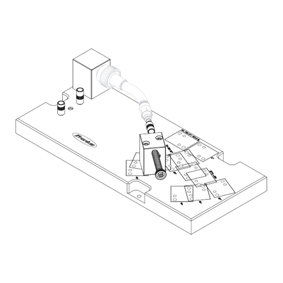
    Prüfvorrichtung Robacta Gesamtsystem - Gesamt- systeme von Roboter-Schweißbrennern prüfen Allgemeines Mit Hilfe der Prüfvorrichtung Robacta Gesamtsystem lassen sich komplette Roboter- Schweißbrenner-Systeme vom Rohrbogen bis zur Roboter-Abschaltbox auf Maßabwei- chungen überprüfen. Für Aufbau und Erstjustierung ist der Anwender verantwortlich. Zur Überprüfung stehen verschiedene Möglichkeiten zur Verfügung, beispielsweise: Rohrbogen Rohrbogen + Schlauchpaket Rohrbogen + Schlauchpaket + Justierschelle...
  • Seite 30: Prüfvorrichtung Justieren Und Erstes Gesamtsystem Prüfen

    Gasdüse entfernen Zur Unterscheidung von Zentrierhülsen und Einstellhülsen sind Einstellhülsen mit zwei zusätzlichen Querrillen ausgestattet. Passende Einstellhülse von der Grundplatte der Prüfvorrichtung Rob- acta Gesamtsystem abschrauben Einstellhülse anstelle des Kontaktroh- res in den Rohrbogen des Gesamtsys- tems einschrauben Einstellhülse einschrauben Der Aufnahmeblock ist zur Montage unter- schiedlicher Roboter-Abschaltboxen vorge- sehen.
  • Seite 31: Gesamtsystem Prüfen

    Aufnahmeblock mit den restlichen Spanneisen diagonal festschrauben Gesamtsystem prüfen: Pass-Stift der Prüfeinheit durch Druck auf die Feder in die Einstellhülse einschieben Das Gesamtsystem ist in Ordnung, wenn der Pass-Stift leichtgängig und vollständig in die Zentrierhülse gleitet, und der Pass-Stift nach Loslassen der Feder auf Grund der Federkraft wieder leichtgängig aus der Zent- rierhülse heraus gleitet.
  • Seite 32 Das Gesamtsystem ist in Ordnung, wenn der Pass-Stift leichtgängig und vollständig in die Zentrierhülse gleitet, und der Pass-Stift nach Loslassen der Feder auf Grund der Federkraft wieder leichtgängig aus der Zentrierhülse heraus gleitet. Gleitet der Pass-Stift nicht leichtgängig in die Zentrierhülse, das Gesamtsystem einrichten.
  • Seite 33: Prüfvorrichtung Robacta Gesamtsystem Twin - Twin-Gesamtsysteme Von Roboter-Schweißbrennern Prüfen

    Prüfvorrichtung Robacta Gesamtsystem Twin - Twin-Gesamtsysteme von Roboter-Schweißbren- nern prüfen Allgemeines Mit Hilfe der Prüfvorrichtung Robacta Gesamtsystem Twin lassen sich komplette Twin Ro- boter-Schweißbrenner-Systeme vom Rohrbogen bis zur Roboter-Abschaltbox auf Maßab- weichungen überprüfen. Für Aufbau und Erstjustierung ist der Anwender verantwortlich. Zur Überprüfung stehen verschiedene Möglichkeiten zur Verfügung, beispielsweise: Rohrbogen Rohrbogen + Schlauchpaket...
  • Seite 34: Prüfvorrichtung Justieren Und Erstes Gesamtsysten Prüfen

    Der Aufnahmeblock ist zur Montage unter- schiedlicher Roboter-Abschaltboxen vorge- sehen. Die Schlauchpakete von den System- komponenten trennen Gasdüse entfernen Twin-Gesamtsystem auf Aufnahmeb- lock schrauben Twin-Gesamtsystem mit Aufnahmeb- lock auf der Grundplatte positionieren Twin-Gesamtsystem und Aufnahmeblock auf der Grundplatte positionieren Prüfvorrichtung Twin-Gesamtsystem mit Aufnahmeb- justieren und ers- lock fluchtend zur Prüfeinheit ausrich-...
  • Seite 35: Twin-Gesamtsystem Prüfen

    Twin-Gesamtsys- tem prüfen Die Schlauchpakete von den Systemkomponenten trennen Gasdüse vom Rohrbogen des Twin-Gesamtsystems entfernen Twin-Gesamtsystem auf Aufnahmeblock (1) schrauben Position der Kontaktrohre durch Druck auf die Feder (2) überprüfen Das Twin-Gesamtsystem ist in Ordnung, wenn die Prüfspitzen (3) genau in die Drahtaustritts-Öffnungen der Kontaktrohre ragen Ist dies nicht der Fall, das Twin-Gesamtsystem mit Aufnahmeblock nachjustieren...
  • Seite 36: Prüfvorrichtung Robacta W / V - Wassergekühlte, Kundenspezifische Roboter-Schweißbrenner Prüfen

    Prüfvorrichtung Robacta W / V - wassergekühlte, kundenspezifische Roboter-Schweißbrenner prüfen Allgemeines Mit Hilfe der Prüfvorrichtung Robacta W / V lassen sich wassergekühlte, kundenspezifi- sche Roboter-Schweißbrenner und Sonderanfertigungen auf Maßabweichungen überprü- fen. Für Aufbau und Erstjustierung ist der Anwender verantwortlich. Prüfvorrichtung Auf der Grundplatte der Prüfvorrichtung vorbereiten Robacta W / V befinden sich 6 mögliche...
  • Seite 37: Prüfvorrichtung Justieren Und Ersten Rohrbogen Prüfen

    Gasdüse entfernen Zur Unterscheidung von Zentrierhülsen und Einstellhülsen sind Einstellhülsen mit zwei zusätzlichen Querrillen ausgestattet. Passende Einstellhülse von der Grundplatte der Prüfvorrichtung Rob- acta W / V abschrauben Einstellhülse anstelle des Kontaktroh- res in den Rohrbogen des Gesamtsys- tems einschrauben Einstellhülse einschrauben Rohrbogen auf die Rohrbogen-Auf- nahme der Grundplatte aufsetzen...
  • Seite 38: Schweißbrenner Prüfen

    Bedienungsanleitung „Richtset Robac- ta“ einrichten. Bei Maßabweichungen > 5 mm (0.197 inch) den Rohrbogen nicht mehr selbst einrichten! In diesem Fall den Rohrbo- gen zur Reparatur an Fronius einsen- Falls vorhanden, alle weiteren bauglei- chen Rohrbögen wie nachfolgend be- schrieben prüfen Schweißbrenner prüfen...
  • Seite 39 Lässt sich der Pass-Stift nicht leichtgängig in die oder aus der Zentrierhülse bewegen, den Rohrbogen gemäß Bedienungsanleitung „Richtset Robacta“ einrichten. Bei Maßabweichungen > 5 mm (0.197 inch) den Rohrbogen nicht mehr selbst einrichten! In diesem Fall den Rohrbogen zur Reparatur an Fronius einsenden...
  • Seite 40: Prüfvorrichtung Robacta G / V - Gasgekühlte, Kundenspezifische Roboter-Schweißbrenner Prüfen

    Prüfvorrichtung Robacta G / V - gasgekühlte, kun- denspezifische Roboter-Schweißbrenner prüfen Allgemeines Mit Hilfe der Prüfvorrichtung Robacta G / V lassen sich gasgekühlte, kundenspezifische Roboter-Schweißbrenner und Sonderanfertigungen auf Maßabweichungen überprüfen. Für Aufbau und Erstjustierung ist der Anwender verantwortlich. Prüfvorrichtung Auf der Grundplatte der Prüfvorrichtung vorbereiten Robacta G / V befinden sich 6 mögliche Po- sitionen zur Montage der Prüfeinheit.
  • Seite 41: Prüfvorrichtung Justieren Und Ersten Rohrbogen Prüfen

    Gasdüse entfernen Zur Unterscheidung von Zentrierhülsen und Einstellhülsen sind Einstellhülsen mit zwei zusätzlichen Querrillen ausgestattet. Passende Einstellhülse von der Grundplatte der Prüfvorrichtung Rob- acta G / V abschrauben Einstellhülse anstelle des Kontaktroh- res in den Rohrbogen des Gesamtsys- tems einschrauben Einstellhülse einschrauben Rohrbogen bis Anschlag in die Rohr- bogen-Aufnahme der Grundplatte ein-...
  • Seite 42: Schweißbrenner Prüfen

    Bedienungsanleitung „Richtset Robac- ta“ einrichten. Bei Maßabweichungen > 5 mm (0.197 inch) den Rohrbogen nicht mehr selbst einrichten! In diesem Fall den Rohrbo- gen zur Reparatur an Fronius einsen- den. Falls vorhanden, alle weiteren bauglei- chen Rohrbögen wie nachfolgend be- schrieben prüfen Schweißbrenner...
  • Seite 43 Lässt sich der Pass-Stift nicht leichtgängig in die oder aus der Zentrierhülse bewegen, den Rohrbogen gemäß Bedienungsanleitung „Richtset Robacta“ einrichten. Bei Maßabweichungen > 5 mm (0.197 inch) den Rohrbogen nicht mehr selbst einrichten! In diesem Fall den Rohrbogen zur Reparatur an Fronius einsenden.
  • Seite 44: Prüfvorrichtung Robacta Twin V - Kundenspezifische Twin Roboter-Schweißbrenner Prüfen

    Prüfvorrichtung Robacta Twin V - kundenspezifi- sche Twin Roboter-Schweißbrenner prüfen Allgemeines Mit Hilfe der Prüfvorrichtung Robacta Twin V lassen sich kundenspezifische Twin Roboter- Schweißbrenner und Sonderanfertigungen auf Maßabweichungen überprüfen. Für Aufbau und Erstjustierung ist der Anwender verantwortlich. Prüfvorrichtung Auf der Grundplatte der Prüfvorrichtung vorbereiten Robacta Twin V befinden sich 6 mögliche Positionen zur Montage der Prüfeinheit.
  • Seite 45: Prüfvorrichtung Justieren Und Ersten Rohrbogen Prüfen

    Der Rohrbogen ist in Ordnung, wenn die Prüfspitzen genau in die Drahtaustritts-Öffnungen der Kon- taktrohre ragen. Bei Maßabweichungen den Rohr- bogen zur Reparatur an Fronius einsenden. Falls vorhanden, alle weiteren bauglei- chen Rohrbögen wie nachfolgend be- schrieben prüfen Rohrbogen-Aufnahme festschrauben...
  • Seite 46 Rohrbogen mittels 2 Überwurfmuttern festschrauben Position der Kontaktrohre durch Druck auf den Pass-Stift der Prüfeinheit (2) überprü- Der Rohrbogen ist in Ordnung, wenn die Prüfspitzen genau in die Drahtaustritts- Öffnungen der Kontaktrohre ragen. Bei Maßabweichungen den Rohrbogen zur Reparatur an Fronius einsenden.
  • Seite 47 Prüfvorrichtung Robacta Compact Pro Twin - kun- denspezifische Twin Roboter-Schweißbrenner prü- Allgemeines Mit Hilfe der Prüfvorrichtung Prüfvorrichtung Robacta Compact Pro Twin lassen sich kun- denspezifische Twin Roboter-Schweißbrenner und Sonderanfertigungen auf Maßabwei- chungen überprüfen. Für Aufbau und Erstjustierung ist der Anwender verantwortlich. Schweißbrenner mit PA-Ausrich- tung prüfen...
  • Seite 48 Den Spannhebel nur per Hand be- tätigen. Keine Verlängerungen ver- wenden. Wenn der Pass-Stifft ohne Wider- stand über die Prüfspitze gleitet, weißt der Schweißbrenner eine TCP-Genauigkeit von 1mm (0.04 inch) auf...
  • Seite 49 Wenn der Pass-Stifft ohne Wider- stand über die Prüfspitze gleitet, weißt der Schweißbrenner eine TCP-Genauigkeit von 1mm (0.04 inch) auf Schweißbrenner mit PA-Ausrich- tung prüfen...
  • Seite 50 Den Spannhebel nur per Hand be- tätigen. Keine Verlängerungen ver- wenden. Wenn der Pass-Stifft ohne Wider- stand über die Prüfspitze gleitet, weißt der Schweißbrenner eine TCP-Genauigkeit von 1mm (0.04 mm) auf...
  • Seite 51 Wenn der Pass-Stifft ohne Wider- stand über die Prüfspitze gleitet, weißt der Schweißbrenner eine TCP-Genauigkeit von 1mm (0.04 mm) auf...
  • Seite 53 Contents General ..............................General ..............................Calibrating the Testing System ......................Required Tools............................Options..............................Scope of Supply............................Robacta W Testing System ........................Robacta G Testing System ........................Robacta Twin Testing System ......................Robacta Twin Professional Testing System ..................Robacta Complete System Testing System ..................Robacta Complete System Twin Testing System.................
  • Seite 54 Testing the Welding Torch ........................Robacta Compact Pro Twin Testing System - Testing Customer-Specific Twin Robot Welding Torches. General ..............................Testing a Welding Torch with PA Alignment..................Testing a Welding Torch with PA Alignment..................
  • Seite 55: General

    Calibrating the In order to achieve optimal test results with the Robacta testing system, it is recommended Testing System that the system is calibrated by Fronius on a yearly basis. Required Tools Allen key, size 6 Contact-tip wrench M6/M8 (42,0410,0570)
  • Seite 56: Options

    Options Steel "Professional" base plate (42,0201,2064) e.g. for frequent testing and straightening work (only factory installation) Steel MTG base plate (42,0201,2512) For frequent testing and straightening work on gas-cooled MIG/MAG welding torches Test shaft W (42,0001,5830) Used to test the Robacta W testing system Test shaft G (42,0001,5831) Used to test the Robacta G testing system...
  • Seite 57: Scope Of Supply

    Scope of Supply Robacta W Test- ing System 1 x torch neck holder 1 x aluminum base plate 1 x testing unit 1 x centering sleeve M8 (Robacta 280 / 300 / 400) 1 x centering sleeve M10 (Robacta 500 / 700) 1 x centering sleeve M6 (Robacta 2500) This document (not shown)
  • Seite 58: Robacta G Testing System

    Robacta G Test- ing System 1 x torch neck holder 1 x aluminum base plate 1 x testing unit 1 x centering sleeve M8 (Robacta 280 / 300 / 400) 1 x centering sleeve M10 (Robacta 500 / 700) 1 x centering sleeve M6 (Robacta 2500) This document (not shown)
  • Seite 59: Robacta Twin Testing System

    Robacta Twin Testing System 1 x torch neck holder 1 x aluminum base plate 1 x testing unit 1 x symmetrical test probe 1 x asymmetrical test probe This document (not shown)
  • Seite 60: Robacta Twin Professional Testing System

    Robacta Twin Professional Testing System 1 x torch neck holder 1 x aluminum base plate 1 x testing unit with pivoting testing tube This document (not shown)
  • Seite 61: Robacta Complete System Testing System

    Robacta Com- plete System Testing System 1 x mounting block 1 x aluminum base plate 1 x testing unit 1 each of M10, M8, and M6 adjusting sleeves 1 each of M10, M8 and M6 centering sleeves 4 x clamps with screws This document (not shown)
  • Seite 62: Robacta Complete System Twin Testing System

    Robacta Com- plete System Twin Testing Sys- 1 x mounting block 1 x aluminum base plate 1 x testing unit 1 x compensating plate 10 mm (0.39 inch) 1 x asymmetrical test probe 1 x symmetrical test probe 4 x clamps with screws This document (not shown)
  • Seite 63: Robacta W / V Testing System

    Robacta W / V Testing System 1 x torch neck holder 1 x aluminum base plate 1 x testing unit 1 each of M10, M8 and M6 centering sleeves 1 each of M10, M8, and M6 adjusting sleeves 4 x clamps with screws This document (not shown)
  • Seite 64: Robacta G / V Testing System

    Robacta G / V Testing System 1 x torch neck holder 1 x aluminum base plate 1 x testing unit 1 each of M10, M8 and M6 centering sleeves 1 each of M10, M8, and M6 adjusting sleeves 4 x clamps with screws This document (not shown)
  • Seite 65: Robacta Twin V Testing System

    Robacta Twin V Testing System 1 x torch neck holder 1 x aluminum base plate 1 x testing unit 1 each of asymmetrical test probes 1 each of symmetrical test probes 4 x clamps with screws This document (not shown)
  • Seite 66: Robacta Compact Pro Twin Testing System

    Robacta Compact Pro Twin Testing System 1 x torch neck holder 1 x aluminum base plate 1 x testing unit This document (not shown)
  • Seite 67: Safety

    This can result in severe personal injury and damage to property. ► All the work and functions described in this document must only be carried out by a Fronius service technician. ► Read and understand this document. ► Read and understand all the Operating Instructions for the system components, espe- cially the safety rules.
  • Seite 68: Robacta W Testing System - Testing Water-Cooled Robot Torch Necks

    Robacta W Testing System - Testing Water-Cooled Robot Torch Necks Preparing the The base plate of the Robacta W testing Testing Unit system contains 13 possible positions for mounting the testing unit. The testing unit is pre-mounted on the 0° mounting position when delivered.
  • Seite 69: Preparing The Torch Neck For Testing

    Preparing the Remove the gas nozzle Torch Neck for Unscrew the contact tip using a cont- Testing act-tip wrench: M6/M8 contact tips ... 7 mm contact-tip wrench M10 contact tips ... 8 mm contact-tip wrench Removing the gas nozzle and contact tip Unscrew the centering sleeve from the base plate: Centering sleeve M10 for Robacta 500...
  • Seite 70: Testing The Torch Neck

    "Robacta Alignment Kit" Operating Instructions For dimensional deviations > 5 mm (0.197 inch), you should no longer set up the torch neck on your own. In this case, please send the torch neck to Fronius for repairs...
  • Seite 71: Robacta G Testing System - Testing Gas-Cooled Robot Torch Necks

    Robacta G Testing System - Testing Gas-Cooled Ro- bot Torch Necks Preparing the The base plate of the Robacta G testing Testing Unit system contains 13 possible positions for mounting the testing unit. The testing unit is pre-mounted on the 0° mounting position when delivered.
  • Seite 72: Preparing The Torch Neck For Testing

    Preparing the Remove the gas nozzle Torch Neck for Unscrew the contact tip using a cont- Testing act-tip wrench: M6/M8 contact tips ... 7 mm contact-tip wrench M10 contact tips ... 8 mm contact-tip wrench Removing the gas nozzle and contact tip Unscrew the centering sleeve from the base plate: Centering sleeve M10 for Robacta...
  • Seite 73: Testing Gas-Cooled Torch Necks

    "Robacta Alignment Kit" Operating Instructions For dimensional deviations > 5 mm (0.197 inch), you should no longer set up the torch neck on your own. In this case, please send the torch neck to Fronius for repairs...
  • Seite 74: Robacta Twin Testing System - Testing Twin Robot Torch Necks

    Robacta Twin Testing System - Testing Twin Robot Torch Necks Preparing the The base plate of the Robacta Twin testing Testing Unit system contains 5 possible positions for mounting the testing unit. For packaging reasons, the testing unit is pre-mounted on the „0° kurz“ mounting po- sition when delivered.
  • Seite 75: Preparing The Torch Neck For Testing

    Preparing the Remove the gas nozzle Torch Neck for Testing Removing the gas nozzle Mounting the Testing System Testing Unit in the Correct Position on the Base Plate for the Torch Neck Curvature of the Welding Torch to be Tested: Remove the test probes from the base plate Select the appropriate test probes ba-...
  • Seite 76: Testing The Torch Neck

    Check the position of the contact tips by pressing on the dowel pin (2) The torch neck is okay if the test probes (3) fit perfectly into the wire outlet open- ings on the contact tips. In the case of dimension deviations, please send the torch neck to Fronius for re- pairs.
  • Seite 77: Robacta Twin Professional Testing System - Testing Twin Robot Torch Necks

    Robacta Twin Professional Testing System - Testing Twin Robot Torch Necks Preparing the The base plate of the Robacta Twin Profes- Testing Unit sional testing system contains 5 possible positions for mounting the testing unit. For packaging reasons, the testing unit is pre-mounted on the "0°...
  • Seite 78: Preparing The Torch Neck For Testing

    Check the position, angle, and orientation of the contact tips relative to one another using the pivoting testing tube The torch neck is okay if the pivoting testing tube glides over both contact tips without resistance In the case of dimension deviations, please send the torch neck to Fronius for re- pairs...
  • Seite 79: Robacta Complete System Testing System - Testing Complete Robot Welding Torch Systems

    Robacta Complete System Testing System - Testing Complete Robot Welding Torch Systems General With the Robacta Complete System testing system you can test complete robot welding torch systems, from the torch neck to the shutoff box, for dimensional deviations. The user is responsible for the setup and initial adjustment. There are various options available for testing, for example: Torch neck Torch neck + hosepack...
  • Seite 80: Calibrating The Testing System And Testing The First Complete System

    Remove the gas nozzle To distinguish between centering sleeves and adjusting sleeves, the adjusting slee- ves are equipped with two additional cross grooves. Unscrew the appropriate adjusting sleeve from the base plate of the Rob- acta Complete System testing system Screw the adjusting sleeve into the torch neck of the complete system ins- tead of the contact tip...
  • Seite 81: Testing The Complete System

    Secure the mounting block by tigh- tening the rest of the clamps in a diago- nal pattern Test the complete system: Insert the testing unit dowel pin into the adjusting sleeve by pressing on the spring The complete system is okay if: The dowel pin glides fully into the centering sleeve with ease The dowel pin glides out of the...
  • Seite 82 If the dowel pin does not glide into the centering sleeve with ease, the complete system must be adjusted.
  • Seite 83: General

    Robacta Complete System Twin Testing System - Testing Complete Twin Robot Welding Torch Sys- tems General With the Robacta Complete System Twin testing system you can test complete Twin robot welding torch systems, from torch neck to robot shutoff box, for dimensional deviations. The user is responsible for the setup and initial adjustment.
  • Seite 84: Calibrating The Testing System And Testing The First Complete System

    The mounting block is designed for moun- ting various robot shutoff boxes. Disconnect the hosepacks from the system components Remove the gas nozzle Screw the Twin complete system onto the mounting block Position the Twin complete system with mounting block on the base plate Positioning the Twin complete system and mounting block on the base plate Calibrating the...
  • Seite 85: Testing The Twin Complete System

    Testing the Twin Complete System Disconnect the hosepacks from the system components Remove the gas nozzle from the torch neck of the Twin complete system Screw the Twin complete system onto the mounting block (1) Check the position of the contact tips by pressing on the spring (2) The Twin complete system is okay if the test probes (3) fit perfectly into the wire outlet openings of the contact tips If this is not the case, the Twin complete system with mounting block must be re-...
  • Seite 86: Robacta W / V Testing System - Testing Water-Cooled, Customer-Specific Robot Welding Torches

    Robacta W / V Testing System - Testing Water- Cooled, Customer-Specific Robot Welding Torches General With the Robacta W / V testing system, you can test water-cooled, customer-specific robot welding torches and special models for dimensional deviations. The user is responsible for the setup and initial adjustment. Preparing the The base plate of the Robacta W / V testing Testing System...
  • Seite 87: Calibrating The Testing System And Testing The First Torch Neck

    Remove the gas nozzle To distinguish between centering sleeves and adjusting sleeves, the adjusting slee- ves are equipped with two additional cross grooves. Unscrew the appropriate adjusting sleeve from the base plate of the Rob- acta W / V testing system Screw the adjusting sleeve into the torch neck of the complete system ins- tead of the contact tip...
  • Seite 88: Testing The Welding Torch

    For dimensional deviations > 5 mm (0.197 inch), you should no longer set up the torch neck on your own. In this case, please send the torch neck to Fronius for repairs If applicable, test all other torch necks of identical construction as described below...
  • Seite 89 "Robacta alignment kit" Operating Instructions. For dimensional deviations > 5 mm (0.197 inch), you should no longer set up the torch neck on your own. In this case, please send the torch neck to Fronius for repairs...
  • Seite 90: Robacta General / V Testing System - Testing Generalas-Cooled, Customer-Specific Robot Welding Torches

    Robacta G / V Testing System - Testing Gas-Cooled, Customer-Specific Robot Welding Torches General With the Robacta G / V testing system, you can test gas-cooled, customer-specific robot welding torches and special models for dimensional deviations. The user is responsible for the setup and initial adjustment. Preparing the The base plate of the Robacta G / V testing Testing System...
  • Seite 91: Calibrating The Testing System And Testing The First Torch Neck

    Remove the gas nozzle To distinguish between centering sleeves and adjusting sleeves, the adjusting slee- ves are equipped with two additional cross grooves. Unscrew the appropriate adjusting sleeve from the base plate of the Rob- acta G / V testing system Screw the adjusting sleeve into the torch neck of the complete system ins- tead of the contact tip...
  • Seite 92: Testing The Welding Torch

    For dimensional deviations > 5 mm (0.197 inch), you should no longer set up the torch neck on your own. In this case, please send the torch neck to Fronius for repairs. If applicable, test all other torch necks of identical construction as described below...
  • Seite 93 "Robacta alignment kit" Operating Instructions. For dimensional deviations > 5 mm (0.197 inch), you should no longer set up the torch neck on your own. In this case, please send the torch neck to Fronius for repairs.
  • Seite 94: Robacta Twin V Testing System - Testing Customer-Specific Twin Robot Welding Torches

    Robacta Twin V Testing System - Testing Customer- Specific Twin Robot Welding Torches General With the Robacta Twin V testing system, you can test customer-specific Twin robot welding torches and special models for dimensional deviations. The user is responsible for the setup and initial adjustment. Preparing the The base plate of the Robacta Twin V tes- Testing System...
  • Seite 95: Calibrating The Testing System And Testing The First Torch Neck

    In the case of dimension devia- tions, please send the torch neck to Fronius for repairs. If applicable, test all other torch necks of identical construction as described below Securing the torch neck holder...
  • Seite 96 Check the position of the contact tips by pressing on the testing unit dowel pin (2) The torch neck is okay if the test probes fit perfectly into the wire outlet openings on the contact tips. In the case of dimension deviations, please send the torch neck to Fronius for re- pairs.
  • Seite 97 Robacta Compact Pro Twin Testing System - Testing Customer-Specific Twin Robot Welding Torches General With the Robacta Compact Pro Twin testing system, you can test customer-specific Twin robot welding torches and special models for dimensional deviations. The user is responsible for the setup and initial adjustment. Testing a Welding Torch with PA Alignment...
  • Seite 98 Only actuate the clamping lever by hand. Do not use any extensions. If the dowel pin glides over the test probe without any resistance, the welding torch has a TCP accuracy of 1 mm (0.04 inch)
  • Seite 99 If the dowel pin glides over the test probe without any resistance, the welding torch has a TCP accuracy of 1 mm (0.04 inch) Testing a Welding Torch with PA Alignment...
  • Seite 100 Only actuate the clamping lever by hand. Do not use any extensions. If the dowel pin glides over the test probe without any resistance, the welding torch has a TCP accuracy of 1 mm (0.04 inch)
  • Seite 101 If the dowel pin glides over the test probe without any resistance, the welding torch has a TCP accuracy of 1 mm (0.04 inch)
  • Seite 103 Sommaire Généralités..............................105 Généralités............................105 Calibrer le dispositif d'essai ........................105 Outillage nécessaire ..........................106 Options..............................106 Livraison..............................107 Dispositif d'essai Robacta W ........................ 107 Dispositif d'essai Robacta G ......................... 108 Dispositif d'essai Robacta Twin ......................109 Dispositif d'essai Robacta Twin Professional ..................110 Dispositif d'essai Robacta Système complet ..................
  • Seite 104 Préparer le dispositif d'essai ......................... 144 Calibrer le dispositif d'essai et contrôler le premier coude..............145 Contrôler la torche de soudage......................146 Dispositif d'essai Robacta Twin Compact Pro – contrôler les torches de soudage robot Twin personnali- sées ................................Généralités............................147 Contrôler une torche de soudage avec orientation PA .................
  • Seite 105: Généralités

    Robacta Twin Compact PRO Calibrer le dispo- Pour obtenir des résultats d'essai optimaux avec le dispositif d'essai Robacta, il est recom- sitif d'essai mandé de faire calibrer annuellement ce dernier chez Fronius.
  • Seite 106: Outillage Nécessaire

    Outillage néces- Clé pour vis à tête six pans creux OC 6 saire Clé de tube de contact M6/M8 (42,0410,0570) Clé de tube de contact M10 (42,0410,0138) Options Plaque de base en acier « Professional » (42,0201,2064) par exemple pour les travaux fréquents d'essai et de réglage (uniquement mon- tage en usine) Plaque de base en acier MTG (42,0201,2512) pour les travaux fréquents d'essai et de réglage de torches de soudage MIG/MAG...
  • Seite 107: Livraison

    Livraison Dispositif d'essai Robacta W 1 x logement pour coude 1 x plaque de base alu 1 x unité d'essai 1 x douille de centrage M8 (Robacta 280 / 300 / 400) 1 x douille de centrage M10 (Robacta 500 / 700) 1 x douille de centrage M6 (Robacta 2500) Le présent document (non représenté)
  • Seite 108: Dispositif D'essai Robacta G

    Dispositif d'essai Robacta G 1 x logement pour coude 1 x plaque de base alu 1 x unité d'essai 1 x douille de centrage M8 (Robacta 280 / 300 / 400) 1 x douille de centrage M10 (Robacta 500 / 700) 1 x douille de centrage M6 (Robacta 2500) Le présent document (non représenté)
  • Seite 109: Dispositif D'essai Robacta Twin

    Dispositif d'essai Robacta Twin 1 x logement pour coude 1 x plaque de base alu 1 x unité d'essai 1 x pointes de contrôle symétriques 1 x pointes de contrôle asymétriques Le présent document (non représenté)
  • Seite 110: Dispositif D'essai Robacta Twin Professional

    Dispositif d'essai Robacta Twin Professional 1 x logement pour coude 1 x plaque de base alu 1 x unité d'essai avec tube d'essai inclinable Le présent document (non représenté)
  • Seite 111: Dispositif D'essai Robacta Système Complet

    Dispositif d'essai Robacta Système complet 1 x bloc support 1 x plaque de base alu 1 x unité d'essai 1 x douille de réglage M10 / M8 / M6 1 x douille de centrage M10 / M8 / M6 4 x brides de serrage avec vis Le présent document (non représenté)
  • Seite 112: Dispositif D'essai Robacta Twin Système Complet

    Dispositif d'essai Robacta Twin Système complet 1 x bloc support 1 x plaque de base alu 1 x unité d'essai 1 x plaque de compensation 10 mm (0.39 inch) 1 x pointes de contrôle asymétriques 1 x pointes de contrôle symétriques 4 x brides de serrage avec vis Le présent document (non représenté)
  • Seite 113: Dispositif D'essai Robacta W / V

    Dispositif d'essai Robacta W / V 1 x logement pour coude 1 x plaque de base alu 1 x unité d'essai 1 x douille de centrage M10 / M8 / M6 1 x douille de réglage M10 / M8 / M6 4 x brides de serrage avec vis Le présent document (non représenté)
  • Seite 114: Dispositif D'essai Robacta G / V

    Dispositif d'essai Robacta G / V 1 x logement pour coude 1 x plaque de base alu 1 x unité d'essai 1 x douille de centrage M10 / M8 / M6 1 x douille de réglage M10 / M8 / M6 4 x brides de serrage avec vis Le présent document (non représenté)
  • Seite 115: Dispositif D'essai Robacta Twin V

    Dispositif d'essai Robacta Twin V 1 x logement pour coude 1 x plaque de base alu 1 x unité d'essai 1 x pointes de contrôle asymétriques 1 x pointes de contrôle symétriques 4 x brides de serrage avec vis Le présent document (non représenté)
  • Seite 116: Dispositif D'essai Robacta Compact Pro Twin

    Dispositif d'essai Robacta Compact Pro Twin 1 x logement pour coude 1 x plaque de base alu 1 x unité d'essai Le présent document (non représenté)
  • Seite 117: Sécurité

    Cela peut entraîner des dommages corporels et matériels graves. ► Toutes les fonctions et tous les travaux décrits dans le présent document doivent uni- quement être exécutés par des techniciens de service Fronius. ► Le présent document doit être lu et compris.
  • Seite 118: Dispositif D'essai Robacta W - Contrôler Les Coudes Robot Refroidis Par Eau

    Dispositif d'essai Robacta W – contrôler les coudes robot refroidis par eau Préparer l'unité 13 positions de montage de l'unité d'essai d'essai sur la plaque de base du dispositif d'essai Robacta W sont possibles. L'unité d'essai est livrée en position de montage 0°.
  • Seite 119: Préparer Le Coude Pour Le Contrôle

    Préparer le coude Retirer la buse de gaz pour le contrôle Dévisser le tube de contact à l'aide d'une clé de tube de contact : Tubes de contact M6/M8 ... Clé de tube de contact OC 7 mm Tubes de contact M10 ... Clé de tube de contact OC 8 mm Retirer la buse de gaz et le tube de contact Dévisser la douille de centrage de la...
  • Seite 120: Contrôler Le Coude

    Instructions de service « Kit de réglage Robacta » Si les écarts de dimensions sont > 5 mm (0.197 inch), le réglage ne doit plus être ef- fectué par vos soins ! Dans ce cas, envoyer le coude à Fronius pour réparation...
  • Seite 121: Dispositif D'essai Robacta G - Contrôler Les Coudes Robot Refroidis Par Gaz

    Dispositif d'essai Robacta G – contrôler les coudes robot refroidis par gaz Préparer l'unité 13 positions de montage de l'unité d'essai d'essai sur la plaque de base du dispositif d'essai Robacta G sont possibles. L'unité d'essai est livrée en position de montage 0°.
  • Seite 122: Préparer Le Coude Pour Le Contrôle

    Préparer le coude Retirer la buse de gaz pour le contrôle Dévisser le tube de contact à l'aide d'une clé de tube de contact : Tubes de contact M6/M8 ... Clé de tube de contact OC 7 mm Tubes de contact M10 ... Clé de tube de contact OC 8 mm Retirer la buse de gaz et le tube de contact Dévisser la douille de centrage de la...
  • Seite 123: Contrôler Le Coude Refroidi Par Gaz

    Instructions de service « Kit de réglage Robacta » Si les écarts de dimensions sont > 5 mm (0.197 inch), le réglage ne doit plus être ef- fectué par vos soins ! Dans ce cas, envoyer le coude à Fronius pour réparation...
  • Seite 124: Dispositif D'essai Robacta Twin - Contrôler Les Coudes Robot Twin

    Dispositif d'essai Robacta Twin – contrôler les coudes robot Twin Préparer l'unité 5 positions de montage de l'unité d'essai d'essai sur la plaque de base du dispositif d'essai Robacta Twin sont possibles. Pour des raisons techniques liées à l'em- ballage, l'unité est livrée en position de montage „0°...
  • Seite 125: Préparer Le Coude Pour Le Contrôle

    Préparer le coude Retirer la buse de gaz pour le contrôle Enlever la buse de gaz Monter l'unité d'essai du dispositif d'essai sur la plaque de base en fonction de l'angle de courbure du coude de la torche de sou- dage à...
  • Seite 126: Contrôler Le Coude

    Contrôler la position des tubes de contact par une pression sur le goujon d'adaptation Le coude est bien réglé lorsque les pointes de contrôle (3) passent précisément dans les orifices de sortie du fil des tubes de contact. En cas d'écarts de dimensions, envoyer le coude à Fronius pour réparation.
  • Seite 127: Dispositif D'essai Robacta Twin Professional - Contrôler Les Coudes Robot Twin

    Dispositif d'essai Robacta Twin Professional – contrôler les coudes robot Twin Préparer l'unité 5 positions de montage de l'unité d'essai d'essai sur la plaque de base du dispositif d'essai Robacta Twin Professional sont possibles. Pour des raisons techniques liées à l'em- ballage, l'unité...
  • Seite 128: Préparer Le Coude Pour Le Contrôle

    Vérifier la position, l'angle et l'orientation des tubes de contact à l'aide du tube d'essai inclinable Le coude est bien réglé lorsque le tube d'essai inclinable peut être glissé facile- ment et sans se coincer sur les deux tubes de contact En cas d'écarts de dimensions, envoyer le coude à Fronius pour réparation...
  • Seite 129: Dispositif D'essai Robacta Pour Système Complet - Contrôler Les Systèmes Complets De Torches De Sou- Dage Robot

    Dispositif d'essai Robacta pour système complet – contrôler les systèmes complets de torches de sou- dage robot Généralités À l'aide du dispositif d'essai Robacta pour système complet, il est possible de vérifier les écarts de dimensions des systèmes de torches de soudage robot complets, du coude au boîtier de déconnexion robot.
  • Seite 130: Calibrer Le Dispositif D'essai Et Contrôler Le Premier Système Complet

    Enlever la buse de gaz Les douilles de réglage disposent de deux rainures transversales supplémentaires pour les différencier des douilles de centra- Dévisser la douille de réglage approp- riée de la plaque de base du dispositif d'essai Robacta Système complet Visser la douille de réglage à...
  • Seite 131: Contrôler Le Système Complet

    Si le goujon d'adaptation ne s'introduit pas ou alors difficilement dans la douille de réglage, réajuster le système complet avec le bloc support Visser le bloc support en diagonale avec la bride de serrage restante Contrôler le système complet : Intro- duire le goujon d'adaptation de l'unité...
  • Seite 132 Introduire le goujon d'adaptation (2) de l'unité d'essai dans la douille de centrage (3) par une pression sur le ressort Le système complet est bien réglé lorsque le goujon d'adaptation entre complètement et facilement dans la douille de centrage, et lorsque le goujon d'adaptation ressort facilement de la douille de centrage suite à...
  • Seite 133: Dispositif D'essai Robacta Twin Système Complet - Contrôler Les Systèmes Complets De Torches De Sou- Dage Robot Twin

    Dispositif d'essai Robacta Twin Système complet – contrôler les systèmes complets de torches de sou- dage robot Twin Généralités À l'aide du dispositif d'essai Robacta Twin Système complet, il est possible de vérifier les écarts de dimensions des systèmes de torches de soudage robot Twin complets, du coude au boîtier de déconnexion robot.
  • Seite 134: Calibrer Le Dispositif D'essai Et Contrôler Le Premier Système Complet

    Le bloc support est destiné au montage de différents boîtiers de déconnexion robots. Déconnecter les faisceaux de liaison des composants périphériques Enlever la buse de gaz Visser le système complet sur le bloc support Positionner le système complet Twin avec bloc support sur la plaque de base Positionner le système complet Twin et le bloc support sur la plaque de base...
  • Seite 135: Contrôler Le Système Complet Twin

    Contrôler le sys- tème complet Twin Déconnecter les faisceaux de liaison des composants périphériques Retirer la buse de gaz du coude du système complet Twin Visser le système complet Twin sur le bloc support (1) Contrôler la position des tubes de contact par une pression sur le ressort (2) Le système complet Twin est bien réglé...
  • Seite 136: Dispositif D'essai Robacta W / V - Contrôler Les Torches De Soudage Robot Personnalisées Refroidies Par Eau

    Dispositif d'essai Robacta W / V – contrôler les torches de soudage robot personnalisées refroidies par eau Généralités À l'aide du dispositif d'essai Robacta W / V, il est possible de vérifier les écarts de dimen- sions des torches de soudage robot personnalisées refroidies par eau et des exécutions spécifiques.
  • Seite 137: Calibrer Le Dispositif D'essai Et Contrôler Le Premier Coude

    Enlever la buse de gaz Les douilles de réglage disposent de deux rainures transversales supplémentaires pour les différencier des douilles de centra- Dévisser la douille de réglage approp- riée de la plaque de base du dispositif d'essai Robacta W / V Visser la douille de réglage à...
  • Seite 138: Contrôler La Torche De Soudage

    Si les écarts de dimensions sont > 5 mm (0.197 inch), le réglage ne doit plus être effectué par vos soins ! Dans ce cas, envoyer le coude à Fronius pour réparation Le cas échéant, contrôler tous les aut- res coudes identiques comme décrit ci- dessous Contrôler la...
  • Seite 139 Instructions de service « Kit de réglage Robacta ». Si les écarts de dimensions sont > 5 mm (0.197 inch), le réglage ne doit plus être effectué par vos soins ! Dans ce cas, envoyer le coude à Fronius pour réparation...
  • Seite 140: Dispositif D'essai Robacta G / V - Contrôler Les Torches De Soudage Robot Personnalisées Refroidies Par Gaz

    Dispositif d'essai Robacta G / V – contrôler les torches de soudage robot personnalisées refroidies par gaz Généralités À l'aide du dispositif d'essai Robacta G / V, il est possible de vérifier les écarts de dimen- sions des torches de soudage robot personnalisées refroidies par gaz et des exécutions spécifiques.
  • Seite 141: Calibrer Le Dispositif D'essai Et Contrôler Le Premier Coude

    Enlever la buse de gaz Les douilles de réglage disposent de deux rainures transversales supplémentaires pour les différencier des douilles de centra- Dévisser la douille de réglage approp- riée de la plaque de base du dispositif d'essai Robacta G / V Visser la douille de réglage à...
  • Seite 142: Contrôler La Torche De Soudage

    Si les écarts de dimensions sont > 5 mm (0.197 inch), le réglage ne doit plus être effectué par vos soins ! Dans ce cas, envoyer le coude à Fronius pour réparation. Le cas échéant, contrôler tous les aut- res coudes identiques comme décrit ci- dessous Contrôler la...
  • Seite 143 Instructions de service « Kit de réglage Robacta ». Si les écarts de dimensions sont > 5 mm (0.197 inch), le réglage ne doit plus être effectué par vos soins ! Dans ce cas, envoyer le coude à Fronius pour réparation.
  • Seite 144: Dispositif D'essai Robacta Twin V - Contrôler Les Torches De Soudage Robot Twin Personnalisées

    Dispositif d'essai Robacta Twin V – contrôler les torches de soudage robot Twin personnalisées Généralités À l'aide du dispositif d'essai Robacta Twin V, il est possible de vérifier les écarts de dimen- sions des torches de soudage robot Twin personnalisées et des exécutions spécifiques. L'utilisateur est responsable du montage et du premier ajustage.
  • Seite 145: Calibrer Le Dispositif D'essai Et Contrôler Le Premier Coude

    En cas d'écarts de dimensions, envoyer le coude à Fronius pour réparation. Le cas échéant, contrôler tous les aut- res coudes identiques comme décrit ci-...
  • Seite 146: Contrôler La Torche De Soudage

    Contrôler la position des tubes de contact par une pression sur le goujon d'adaptation de l'unité d'essai (2) Le coude est bien réglé lorsque les pointes de contrôle passent précisément dans les orifices de sortie du fil des tubes de contact. En cas d'écarts de dimensions, envoyer le coude à Fronius pour réparation.
  • Seite 147: Dispositif D'essai Robacta Twin Compact Pro - Contrôler Les Torches De Soudage Robot Twin Personnali- Sées

    Dispositif d'essai Robacta Twin Compact Pro – contrôler les torches de soudage robot Twin person- nalisées Généralités À l'aide du dispositif d'essai Robacta Twin Compact Pro, il est possible de vérifier les écarts de dimensions des torches de soudage robots Twin personnalisées et des exécutions spé- cifiques.
  • Seite 148 Actionner le levier de serrage uniquement à la main. Ne pas utili- ser de rallonge. Lorsque le goujon d'adaptation peut être glissé sans se coincer sur la pointe de contrôle, la torche de sou- dage présente une précision TCP d'1 mm (0.04 inch)
  • Seite 149: Contrôler Une Torche De Soudage Avec Orientation Pa

    Lorsque le goujon d'adaptation peut être glissé sans se coincer sur la pointe de contrôle, la torche de sou- dage présente une précision TCP d'1 mm (0.04 inch) Contrôler une torche de sou- dage avec orien- tation PA...
  • Seite 150 Actionner le levier de serrage uniquement à la main. Ne pas utili- ser de rallonge. Lorsque le goujon d'adaptation peut être glissé sans se coincer sur la pointe de contrôle, la torche de sou- dage présente une précision TCP d'1 mm (0.04 inch)
  • Seite 151 Lorsque le goujon d'adaptation peut être glissé sans se coincer sur la pointe de contrôle, la torche de sou- dage présente une précision TCP d'1 mm (0.04 inch)
  • Seite 153 Spis treści Informacje ogólne ............................155 Informacje ogólne ..........................155 Kalibracja przyrządu kontrolnego......................155 Potrzebne narzędzia ..........................156 Opcje..............................156 Zakres dostawy............................157 Przyrząd kontrolny Robacta W ......................157 Przyrząd kontrolny Robacta G ......................158 Przyrząd kontrolny Robacta Twin ......................159 Przyrząd kontrolny Robacta Twin Professional ..................
  • Seite 154 Informacje ogólne ..........................194 Przygotowanie przyrządu kontrolnego....................194 Wyregulować przyrząd kontrolny i skontrolować pierwszą końcówkę palnika........195 Skontrolować palnik spawalniczy......................196 Przyrząd kontrolny Robacta Compact Pro Twin – kontrola specyficznego dla klienta palnika spawalnicze- go do aplikacji zrobotyzowanych typu Twin ....................Informacje ogólne ..........................
  • Seite 155: Informacje Ogólne

    Robacta Twin Compact PRO Kalibracja przy- Aby w pracy z przyrządem kontrolnym Robacta móc uzyskać optymalne wyniki kontroli, rządu kontrolne- zalecamy, aby raz w roku zlecać kalibrację przyrządu kontrolnego w firmie Fronius.
  • Seite 156: Potrzebne Narzędzia

    Potrzebne narzę- Klucz imbusowy o rozmiarze 6 dzia Klucz do końcówek prądowych, M6 / M8 (42,0410,0570) Klucz do końcówek prądowych M10 (42,0410,0138) Opcje Płyta podstawowa stalowa „Professional” (42,0201,2064) przykładowo do częstych prac kontrolnych i prostowania końcówek (tylko montaż fabryczny) Płyta podstawowa stalowa MTG (42,0201,2512) do częstych prac kontrolnych i prostowania chłodzonych gazem palników spawal- niczych MIG/MAG Wałek kontrolny W (42,0001,5830)
  • Seite 157: Zakres Dostawy

    Zakres dostawy Przyrząd kontrol- ny Robacta W 1 x uchwyt końcówki palnika 1 x płyta podstawowa aluminiowa 1 x jednostka kontrolna 1 x tuleja centrująca M8 (Robacta 280 / 300 / 400) 1 x tuleja centrująca M10 (Robacta 500 / 700) 1 x tuleja centrująca M6 (Robacta 2500) niniejszy dokument (nieprzedstawiony)
  • Seite 158: Przyrząd Kontrolny Robacta G

    Przyrząd kontrol- ny Robacta G 1 x uchwyt końcówki palnika 1 x płyta podstawowa aluminiowa 1 x jednostka kontrolna 1 x tuleja centrująca M8 (Robacta 280 / 300 / 400) 1 x tuleja centrująca M10 (Robacta 500 / 700) 1 x tuleja centrująca M6 (Robacta 2500) niniejszy dokument (nieprzedstawiony)
  • Seite 159: Przyrząd Kontrolny Robacta Twin

    Przyrząd kontrol- ny Robacta Twin 1 x uchwyt końcówki palnika 1 x płyta podstawowa aluminiowa 1 x jednostka kontrolna 1 x końcówka kontrolna symetryczna 1 x końcówka kontrolna asymetryczna niniejszy dokument (nieprzedstawiony)
  • Seite 160: Przyrząd Kontrolny Robacta Twin Professional

    Przyrząd kontrol- ny Robacta Twin Professional 1 x uchwyt końcówki palnika 1 x płyta podstawowa aluminiowa 1 x jednostka kontrolna z przechylną rurą kontrolną niniejszy dokument (nieprzedstawiony)
  • Seite 161: Przyrząd Kontrolny Robacta - System Całościowy

    Przyrząd kontrol- ny Robacta – sys- tem całościowy 1 x blok mocujący 1 x płyta podstawowa aluminiowa 1 x jednostka kontrolna po 1 x tulei nastawczej M10 / M8 / M6 po 1 x tulei centrującej M10 / M8 / M6 4 x docisk ze śrubami niniejszy dokument (nieprzedstawiony)
  • Seite 162: Przyrząd Kontrolny Robacta - System Całościowy Twin

    Przyrząd kontrol- ny Robacta – sys- tem całościowy Twin 1 x blok mocujący 1 x płyta podstawowa aluminiowa 1 x jednostka kontrolna 1 x płyta wyrównawcza 10 mm (0.39 inch) 1 x końcówka kontrolna asymetryczna 1 x końcówka kontrolna symetryczna 4 x docisk ze śrubami niniejszy dokument (nieprzedstawiony)
  • Seite 163: Przyrząd Kontrolny Robacta W / V

    Przyrząd kontrol- ny Robacta W / V 1 x uchwyt końcówki palnika 1 x płyta podstawowa aluminiowa 1 x jednostka kontrolna po 1 x tulei centrującej M10 / M8 / M6 po 1 x tulei nastawczej M10 / M8 / M6 4 x docisk ze śrubami niniejszy dokument (nieprzedstawiony)
  • Seite 164: Przyrząd Kontrolny Robacta G / V

    Przyrząd kontrol- ny Robacta G / V 1 x uchwyt końcówki palnika 1 x płyta podstawowa aluminiowa 1 x jednostka kontrolna po 1 x tulei centrującej M10 / M8 / M6 po 1 x tulei nastawczej M10 / M8 / M6 4 x docisk ze śrubami niniejszy dokument (nieprzedstawiony)
  • Seite 165: Przyrząd Kontrolny Robacta Twin V

    Przyrząd kontrol- ny Robacta Twin 1 x uchwyt końcówki palnika 1 x płyta podstawowa aluminiowa 1 x jednostka kontrolna po 1 x końcówki kontrolne asymetryczne po 1 x końcówki kontrolne symetryczne 4 x docisk ze śrubami niniejszy dokument (nieprzedstawiony)
  • Seite 166: Przyrząd Kontrolny Robacta Compact Pro Twin

    Przyrząd kontrol- ny Robacta Com- pact Pro Twin 1 x uchwyt końcówki palnika 1 x płyta podstawowa aluminiowa 1 x jednostka kontrolna niniejszy dokument (nieprzedstawiony)
  • Seite 167: Bezpieczeństwo

    Skutkiem mogą być poważne uszczerbki na zdrowiu i straty materialne. ► Wszystkie prace i funkcje opisane w tym dokumencie mogą być wykonywane tylko przez techników serwisowych Fronius. ► Należy dokładnie zapoznać się z niniejszym dokumentem. ► Należy dokładnie zapoznać się ze wszystkimi instrukcjami obsługi komponentów sys- temu, w szczególności przepisami dotyczącymi bezpieczeństwa.
  • Seite 168: Przyrząd Kontrolny Robacta W - Kontrola Chłodzonych Wodą Końcówek Palnika Robota

    Przyrząd kontrolny Robacta W – kontrola chłodzo- nych wodą końcówek palnika robota Przygotowanie Na płycie podstawowej przyrządu kontrol- jednostki kontrol- nego Robacta W znajduje się 13 możliwych pozycji do montażu jednostki kontrolnej. W momencie dostawy jednostka kontrolna jest zamontowana w pozycji montażowej 0°.
  • Seite 169: Przygotowanie Końcówki Palnika Do Sprawdzenia

    Przygotowanie Zdjąć dyszę gazową końcówki palnika Odkręcić końcówkę prądową przy uży- do sprawdzenia ciu klucza do końcówek prądowych: Końcówki prądowe M6/M8 ... klucz do końcówek prądowych, rozwartość 7 Końcówki prądowe M10 ... klucz do końcówek prądowych, rozwartość 8 Zdejmowanie dyszy gazowej i końcówki prądowej Odkręcić...
  • Seite 170: Sprawdzanie Końcówki Palnika

    Jeśli kołek pasowany nie porusza się swobodnie w tulei centrującej, końcówkę palnika należy wyprostować zgodnie z instrukcją obsługi „Zestaw do prostowania Robacta” W przypadku odchyłek wymiarowych > 5 mm (0.197 inch) nie należy już samodzielnie prostować końcówki palnika! W takim przypadku należy wysłać końcówkę palnika do naprawy do firmy Fronius...
  • Seite 171: Przyrząd Kontrolny Robacta G - Kontrola Chłodzonych Gazem Końcówek Palnika Robota

    Przyrząd kontrolny Robacta G – kontrola chłodzo- nych gazem końcówek palnika robota Przygotowanie Na płycie podstawowej przyrządu kontrol- jednostki kontrol- nego Robacta G znajduje się 13 możliwych pozycji do montażu jednostki kontrolnej. W momencie dostawy jednostka kontrolna jest zamontowana w pozycji montażowej 0°.
  • Seite 172: Przygotowanie Końcówki Palnika Do Sprawdzenia

    Przygotowanie Zdjąć dyszę gazową końcówki palnika Odkręcić końcówkę prądową przy uży- do sprawdzenia ciu klucza do końcówek prądowych: Końcówki prądowe M6/M8 ... klucz do końcówek prądowych, rozwartość 7 Końcówki prądowe M10 ... klucz do końcówek prądowych, rozwartość 8 Zdejmowanie dyszy gazowej i końcówki prądowej Odkręcić...
  • Seite 173: Sprawdzanie Chłodzonych Gazem Końcówek Palnika

    Końcówka palnika musi swobodnie wsuwać się do uchwytu końcówki palnika; je- śli końcówka palnika nie daje się wsunąć lub z trudem wsuwa się do uchwytu koń- cówki palnika, wysłać końcówkę palnika do pomiaru do firmy Fronius. Przykręcić końcówkę palnika do uchwytu końcówki palnika za pomocą śruby z łbem o gnieździe sześciokątnym M5 x 20 mm...
  • Seite 174: Przyrząd Kontrolny Robacta Twin - Kontrola Końcówek Palnika Robota Twin

    Przyrząd kontrolny Robacta Twin – kontrola końcó- wek palnika robota Twin Przygotowanie Na płycie podstawowej przyrządu kontrol- jednostki kontrol- nego Robacta Twin znajduje się 5 możli- wych pozycji do montażu jednostki kontrolnej. Ze względu na sposób zapakowania w mo- mencie dostawy jednostka kontrolna jest zamontowana w pozycji montażowej „0°...
  • Seite 175: Przygotowanie Końcówki Palnika Do Sprawdzenia

    Przygotowanie Zdjąć dyszę gazową końcówki palnika do sprawdzenia Wyjąć dyszę gazową Zamontować na płycie podstawowej jed- nostkę kontrolną przyrządu odpowiednio do skrzywienia korpusu kontrolowanego palnika spawalniczego: Zdjąć końcówki kontrolne z płyty pod- stawowej Zależnie od tego, czy kontrolowana końcówka palnika Twin jest symetrycz- na, czy też...
  • Seite 176: Sprawdzanie Końcówki Palnika

    Sprawdzić pozycję końcówek prądowych poprzez naciśnięcie kołka pasowanego (2) Stan końcówki palnika jest prawidłowy, gdy końcówki kontrolne (3) wchodzą do- kładnie do otworów wylotowych drutu końcówek prądowych. W razie odstępstw wymiarowych należy wysłać końcówkę palnika do naprawy do firmy Fronius.
  • Seite 177: Przyrząd Kontrolny Robacta Twin Professional - Kontrola Końcówek Palnika Robota Twin

    Przyrząd kontrolny Robacta Twin Professional – kontrola końcówek palnika robota Twin Przygotowanie Na płycie podstawowej przyrządu kontrol- jednostki kontrol- nego Robacta Twin Professional znajduje się 5 możliwych pozycji do montażu jed- nostki kontrolnej. Ze względu na sposób zapakowania w mo- mencie dostawy jednostka kontrolna jest zamontowana w pozycji montażowej 0°.
  • Seite 178: Przygotowanie Końcówki Palnika Do Sprawdzenia

    Sprawdzić pozycję, kąt i położenie końcówek prądowych przy użyciu przechylnej rury kontrolnej Stan końcówki palnika jest prawidłowy, gdy przechylna rura kontrolna przesuwa się bez oporu przez obie końcówki prądowe W razie odstępstw wymiarowych należy wysłać końcówkę palnika do naprawy do firmy Fronius...
  • Seite 179: Przyrząd Kontrolny Robacta - System Całościowy - Kontrola Całych Systemów Palników Spawalniczych Do Aplikacji Zrobotyzowanych

    Przyrząd kontrolny Robacta – system całościowy – kontrola całych systemów palników spawalniczych do aplikacji zrobotyzowanych Informacje ogól- Za pomocą przyrządu kontrolnego Robacta do systemów całościowych można kontrolo- wać pod względem odstępstw wymiarowych całe systemy palników spawalniczych do apli- kacji zrobotyzowanych, od końcówki palnika do modułu wyłączania robota. Za montaż...
  • Seite 180 Odkręcić dopasowaną tuleję nasta- wczą od płyty podstawowej przyrządu kontrolnego Robacta do systemów całościowych Wkręcić tuleję nastawczą zamiast końcówki prądowej do końcówki palni- ka systemu całościowego Wkręcanie tulei nastawczej Wyjąć dyszę gazową Do rozróżnienia tulei centrujących i nasta- wczych tuleje nastawcze wyposażono w dwa dodatkowe rowki poprzeczne.
  • Seite 181: Wyregulować Przyrząd Kontrolny I Skontrolować Pierwszy System Całościowy

    Wyregulować Wyrównać system całościowy z blo- przyrząd kontrol- kiem uchwytu zbieżnie do jednostki ny i skontrolować kontrolnej, odstęp od tulei nastawczej pierwszy system musi wynosić co najmniej 15 mm (0.59 całościowy inch) Lekko przykręcić blok mocujący przy użyciu docisku Skontrolować system całościowy: na- ciskając na sprężynę...
  • Seite 182: Kontrola Systemu Całościowego

    Kontrola systemu całościowego Odłączyć wiązkę uchwytu od komponentów systemu Wyjąć dyszę gazową i końcówkę prądową końcówki palnika systemu całościowego Wkręcić pasującą tuleję centrującą do końcówki palnika Przykręcić system całościowy na bloku mocującym (1) Naciskając na sprężynę wsunąć kołek pasowany (2) jednostki kontrolnej do tulei cen- trującej (3) Stan całego systemu jest prawidłowy, gdy kołek pasowany wykazuje swobodę...
  • Seite 183: Przyrząd Kontrolny Robacta Do Systemów Całościowych Twin - Kontrola Systemów Całościowych Twin Do Palników Spawalniczych Do Aplikacji Zrobotyzowanych

    Przyrząd kontrolny Robacta do systemów całościo- wych Twin – kontrola systemów całościowych Twin do palników spawalniczych do aplikacji zrobotyzo- wanych Informacje ogól- Za pomocą przyrządu kontrolnego Robacta do systemów całościowych Twin można kon- trolować pod względem odstępstw wymiarowych całe systemy palników spawalniczych do aplikacji zrobotyzowanych typu Twin, od końcówki palnika do modułu wyłączania robota.
  • Seite 184: Regulacja Przyrządu Kontrolnego I Kontrola Pierwszego Systemu Całościowego

    Blok mocujący jest przeznaczony do mon- tażu różnych modułów wyłączania robota. Odłączyć wiązki uchwytu od kompo- nentów systemu Wyjąć dyszę gazową Przykręcić system całościowy Twin na bloku mocującym Umieścić system całościowy Twin z blokiem mocującym na płycie podsta- wowej Umiejscowienie systemu całościowego Twin i bloku mocującego na płycie podstawowej Regulacja przy- Wyrównać...
  • Seite 185: Kontrola Systemu Całościowego Twin

    Kontrola systemu całościowego Twin Odłączyć wiązki uchwytu od komponentów systemu Wyjąć dyszę gazową z końcówki palnika systemu całościowego Twin Przykręcić system całościowy Twin na bloku mocującym (1) Sprawdzić pozycję końcówek prądowych poprzez naciśnięcie sprężyny (2) System całościowy Twin jest w porządku, gdy końcówki kontrolne (3) wchodzą dokładnie do otworów wylotowych drutu końcówek prądowych Jeśli tak nie jest, należy ponownie wyregulować...
  • Seite 186: Przyrząd Kontrolny Robacta W / V - Kontrola Chłodzonych Wodą, Specyficznych Dla Klienta Końcówek Pal- Nika Spawalniczego Do Aplikacji Zrobotyzowanych

    Przyrząd kontrolny Robacta W / V – kontrola chło- dzonych wodą, specyficznych dla klienta końcówek palnika spawalniczego do aplikacji zrobotyzowa- nych Informacje ogól- Za pomocą przyrządu kontrolnego Robacta W / V można kontrolować chłodzone wodą, specyficzne dla klienta palniki spawalnicze do aplikacji zrobotyzowanych i wersje specjal- ne pod względem odstępstw wymiarowych.
  • Seite 187: Wyregulować Przyrząd Kontrolny I Skontrolować Pierwszą Końcówkę Palnika

    Wyjąć dyszę gazową Do rozróżnienia tulei centrujących i nasta- wczych tuleje nastawcze wyposażono w dwa dodatkowe rowki poprzeczne. Odkręcić dopasowaną tuleję nasta- wczą od płyty podstawowej przyrządu kontrolnego Robacta W / V Wkręcić tuleję nastawczą zamiast końcówki prądowej do końcówki palni- ka systemu całościowego Wkręcanie tulei nastawczej Założyć...
  • Seite 188: Skontrolować Palnik Spawalniczy

    5 mm (0.197 inch) nie należy już samo- dzielnie prostować końcówki palnika! W takim przypadku należy wysłać końcówkę palnika do naprawy do firmy Fronius Jeżeli są, skontrolować wszystkie inne końcówki palnika o takiej samej konst- rukcji zgodnie z poniższym opisem Skontrolować...
  • Seite 189 Jeśli kołek pasowany nie porusza się swobodnie w tulei centrującej, wyprostować końców- kę palnika zgodnie z instrukcją obsługi „Zestaw do prostowania Robacta”. W przypadku odchyłek wymiarowych > 5 mm (0.197 inch) nie należy już samodzielnie pro- stować końcówki palnika! W takim przypadku należy wysłać końcówkę palnika do naprawy do firmy Fronius...
  • Seite 190: Przyrząd Kontrolny Robacta G / V - Kontrola Chłodzonych Gazem, Specyficznych Dla Klienta Końcówek Palnika Spawalniczego Do Aplikacji Zrobotyzowanych

    Przyrząd kontrolny Robacta G / V – kontrola chłodzo- nych gazem, specyficznych dla klienta końcówek palnika spawalniczego do aplikacji zrobotyzowa- nych Informacje ogól- Za pomocą przyrządu kontrolnego Robacta G / V można kontrolować chłodzone gazem, specyficzne dla klienta palniki spawalnicze do aplikacji zrobotyzowanych i wersje specjal- ne pod względem odstępstw wymiarowych.
  • Seite 191: Wyregulować Przyrząd Kontrolny I Skontrolować Pierwszą Końcówkę Palnika

    Wyjąć dyszę gazową Do rozróżnienia tulei centrujących i nasta- wczych tuleje nastawcze wyposażono w dwa dodatkowe rowki poprzeczne. Odkręcić dopasowaną tuleję nasta- wczą od płyty podstawowej przyrządu kontrolnego Robacta G / V Wkręcić tuleję nastawczą zamiast końcówki prądowej do końcówki palni- ka systemu całościowego Wkręcanie tulei nastawczej Wsunąć...
  • Seite 192: Skontrolować Palnik Spawalniczy

    5 mm (0.197 inch) nie należy już samo- dzielnie prostować końcówki palnika! W takim przypadku należy wysłać końcówkę palnika do naprawy do firmy Fronius. Jeżeli są, skontrolować wszystkie inne końcówki palnika o takiej samej konst- rukcji zgodnie z poniższym opisem Skontrolować...
  • Seite 193 Jeśli kołek pasowany nie porusza się swobodnie w tulei centrującej, wyprostować końców- kę palnika zgodnie z instrukcją obsługi „Zestaw do prostowania Robacta”. W przypadku odchyłek wymiarowych > 5 mm (0.197 inch) nie należy już samodzielnie pro- stować końcówki palnika! W takim przypadku należy wysłać końcówkę palnika do naprawy do firmy Fronius.
  • Seite 194: Przyrząd Kontrolny Robacta Twin V - Kontrola Specyficznego Dla Klienta Palnika Spawalniczego Do Apli- Kacji Zrobotyzowanych Typu Twin

    Przyrząd kontrolny Robacta Twin V – kontrola spe- cyficznego dla klienta palnika spawalniczego do aplikacji zrobotyzowanych typu Twin Informacje ogól- Za pomocą przyrządu kontrolnego Robacta Twin V można kontrolować specyficzne dla klienta palniki spawalnicze do aplikacji zrobotyzowanych typu Twin i wersje specjalne pod względem odstępstw wymiarowych.
  • Seite 195: Wyregulować Przyrząd Kontrolny I Skontrolować Pierwszą Końcówkę Palnika

    W razie odstępstw wymiarowych należy wysłać końcówkę palnika do naprawy do firmy Fronius. Jeżeli są, skontrolować wszystkie inne końcówki palnika o takiej samej konst- rukcji zgodnie z poniższym opisem Przykręcanie uchwytu końcówki palnika...
  • Seite 196: Skontrolować Palnik Spawalniczy

    Sprawdzić pozycję końcówek prądowych poprzez naciśnięcie kołka pasowanego jed- nostki kontrolnej (2) Stan końcówki palnika jest prawidłowy, gdy końcówki kontrolne wchodzą dokład- nie do otworów wylotowych drutu końcówek prądowych. W razie odstępstw wymiarowych należy wysłać końcówkę palnika do naprawy do firmy Fronius.
  • Seite 197: Przyrząd Kontrolny Robacta Compact Pro Twin - Kontrola Specyficznego Dla Klienta Palnika Spawalnicze- Go Do Aplikacji Zrobotyzowanych Typu Twin

    Przyrząd kontrolny Robacta Compact Pro Twin – kontrola specyficznego dla klienta palnika spawalni- czego do aplikacji zrobotyzowanych typu Twin Informacje ogól- Za pomocą przyrządu kontrolnego Robacta Compact Pro Twin można kontrolować specy- ficzne dla klienta palniki spawalnicze do aplikacji zrobotyzowanych typu Twin i wersje spe- cjalne pod względem odstępstw wymiarowych.
  • Seite 198 Dźwignię mocującą naciskać tylko ręcznie. Nie stosować przedłużek. Jeśli kołek pasowany przesuwa się bez oporu przez końcówkę kont- rolną, palnik spawalniczy ma dokładność TCP 1 mm (0.04 inch)
  • Seite 199: Kontrola Palnika Spawalniczego Z Wyrównaniem Pa

    Jeśli kołek pasowany przesuwa się bez oporu przez końcówkę kont- rolną, palnik spawalniczy ma dokładność TCP 1 mm (0.04 inch) Kontrola palnika spawalniczego z wyrównaniem PA...
  • Seite 200 Dźwignię mocującą naciskać tylko ręcznie. Nie stosować przedłużek. Jeśli kołek pasowany przesuwa się bez oporu przez końcówkę kont- rolną, palnik spawalniczy ma dokładność TCP 1 mm (0.04 inch)
  • Seite 201 Jeśli kołek pasowany przesuwa się bez oporu przez końcówkę kont- rolną, palnik spawalniczy ma dokładność TCP 1 mm (0.04 inch)
  • Seite 204 FRONIUS INTERNATIONAL GMBH Froniusstraße 1, A-4643 Pettenbach, Austria E-Mail: sales@fronius.com www.fronius.com Under www.fronius.com/contact you will find the addresses of all Fronius Sales & Service Partners and locations...

Inhaltsverzeichnis