Herunterladen Inhalt Inhalt Diese Seite drucken
Stryker XPRT Bedienungs- Und Wartungshandbuch

Stryker XPRT Bedienungs- Und Wartungshandbuch

Therapeutische auflagefläche integriert in modell fl27 (2155/2156)
Inhaltsverzeichnis

Werbung

Verfügbare Sprachen
  • DE

Verfügbare Sprachen

  • DEUTSCH, seite 149
Therapeutic Support Surface
Surface de soutien thérapeutique
Therapeutische Auflagefläche
Therapeutisch steunoppervlak
Superficie de apoyo terapéutico
Superfície de suporte terapêutico
For Parts or Technical Assistance:
Service technique et pièces de rechange :
Für Ersatzteile oder technische Hilfe:
Voor onderdelen of technische bijstand:
Para solicitar asistencia técnica o piezas:
Para encomendar peças ou solicitar assistência técnica:
USA/États-Unis/USA/VS/EE. UU/EUA: 1-800-327-0770
2012/06 B.0
XPRT™
Operations/Maintenance Manual
2950-109-005 REV B
REF
Integrated with FL27 (2155/2156)
Intégré avec FL27 (2155/2156)
Integriert in Modell FL27 (2155/2156)
Geïntegreerd met FL27 (2155/2156)
Integración con FL27 (2155/2156)
Integrado com o FL27 (2155/2156)
Manuel d'utilisation et d'entretien
Bedienungs- und Wartungshandbuch
Gebruiks-/onderhoudshandleiding
Manual de uso y mantenimiento
Manual de funcionamento/manutenção
2950
transparent
outline with
White letters and
rectangle
0086
www.stryker.com

Werbung

Inhaltsverzeichnis
loading

Inhaltszusammenfassung für Stryker XPRT

  • Seite 1 XPRT™ 2950 White letters and outline with transparent rectangle Therapeutic Support Surface Integrated with FL27 (2155/2156) Surface de soutien thérapeutique Intégré avec FL27 (2155/2156) Therapeutische Auflagefläche Integriert in Modell FL27 (2155/2156) Therapeutisch steunoppervlak Geïntegreerd met FL27 (2155/2156) Superficie de apoyo terapéutico Integración con FL27 (2155/2156)
  • Seite 3 FRANCE Stryker Portugal Produtos Stryker France S.A.S. Medicos, LTDA. EASTERN EUROPE ZAC - Avenue de Satolas Green Avenida Marechal Gomes Stryker SA - Export Business 69330 Pusignan da Costa, 35 Grand-Rue 90 France 1800-255 Lisboa P.O. Box 1567 Phone: 011-33-472-45-36-00...
  • Seite 5: Inhaltsverzeichnis

    To Change the Displayed Language . . . . . . . . . . . . . . . . . . . . . . . . . . . . . . . . . . . . . . . . . . . . . . . . . . . . . . . 1-29 www.stryker.com 2950-109-005 REV B...
  • Seite 6 Transferring a Patient From the XPRT™ Therapeutic Support Surface . . . . . . . . . . . . . . . .
  • Seite 7: Symbols And Definitions

    . Consult Instructions for Use Model Number Manufacturer Damp Wipe Only 10% Chlorinated Bleach Do Not Tumble Dry Do Not Iron Do Not Dry-Clean Allow to Completely Air Dry Return To Table of Contents www.stryker.com 2950-109-005 REV B...
  • Seite 8: Warning/Caution/Note Definition

    . NOTE Provides special information to make maintenance easier or important instructions clearer . Return To Table of Contents 2950-109-005 REV B www.stryker.com...
  • Seite 9: Brief Product Description And Intended Use Statement

    (CLRT) . XPRT offers turn assist and pressure redistribution . XPRT also offers a powered low air loss feature to provide a flow of air and a breathable cover to assist in maintaining the micro-climate of the skin .
  • Seite 10: Product Illustration

    Introduction PRODUCT ILLUSTRATION Head End Head Box CPR Plug Foot End Foot Box Return To Table of Contents 2920-009-005 REV A www.stryker.com...
  • Seite 11: Specifications

    IEC60601-1 CAN/CSA C22 .2 No . 601 . 1 .-M90 Electromagnetic compatibility, meets IEC60601-1-2 (CISPR 11 classified as Class A, Group 1 ISM equipment) Return To Table of Contents www.stryker.com 2950-109-005 REV B...
  • Seite 12: Contact Information

    3800 E . Centre Avenue Portage, MI 49002 Please have the serial number (A) of your Stryker product available when calling Stryker Customer Service or Technical Support . Include the serial number in all written communication . PRODUCT SERIAL NUMBER LOCATION/IDENTIFICATION The serial number (A) is located on the label located on the front of the foot box and again at (B) on the head box of the support surface as shown in Figure 1 .
  • Seite 13: Summary Of Safety Precautions

    • Portable and mobile RF communication equipment can affect Medical Electrical Equipment . • Risk of injury . Use of XPRT therapeutic support surface for stroke victims should be only under physician’s order . • It is the caregiver’s responsibility to monitor the patient’s condition at regular intervals to ensure patient safety .
  • Seite 14 . • The XPRT™ therapeutic support surface should not be used adjacent to or stacked with other equipment to avoid malfunction (excluding on a bed) . If adjacent or stacked use is necessary, the XPRT™ therapeutic support surface should be observed to verify normal operation in the configuration in which it will be used .
  • Seite 15: Contraindications

    Summary of Safety Precautions English CONTRAINDICATIONS Stryker Medical promotes the clinical assessment of each patient’s condition and appropriate therapy administration by the caregiver . Air support therapy is not recommended for patients with unstable fractures, unstable spinal cord injuries or those in skeletal traction .
  • Seite 16: Setup Procedures

    To Power Source Outlet on Bed Frame . Place foot box on foot end of bed litter . CAUTION • The XPRT™ therapeutic support surface should not be used adjacent to or stacked with other equipment to avoid malfunction (excluding on a bed) . If adjacent or stacked use is necessary, the XPRT™...
  • Seite 17 . • To avoid possible injury confirm proper scale system operation following support surface installation . For best results, secure the XPRT™ therapeutic support surface power cord to prevent damage to the cord and interference with the bed frame and the scale system .
  • Seite 18: Powering Up The Support Surface

    PAUSED . SIDERAIL POSITION The position of the siderails determines the functionality of the XPRT™ . All the therapies including Max Inflate, Firmness and Turn Assist, will function if the siderails are unlocked, except for the rotation therapy. If a siderail is unlocked during the rotation therapy, this therapy will automatically stop .
  • Seite 19: Xprt™ Clinical Functions

    XPRT™ is a pressure redistributing therapeutic support surface that assists with pulmonary management . LOW AIR LOSS (LAL) XPRT™ provides continuous flow of air through the multi-zoned support surface . LAL assists with skin management of microclimate at the interface of skin and support surface .
  • Seite 20: To Prepare For Rotation Therapy

    . • Risk of injury . Use of XPRT therapeutic support surface for stroke victims should be only under physician’s order . • Rotation angle settings approximate the degrees of rotation achieved by a 165 pound patient with an 18 inch shoulder width .
  • Seite 21 . • All Therapy parameters are stored until changed or reset . • To reset the parameters to the default values, refer to “Advanced Settings” on page 1-29 . Return To Table of Contents www.stryker.com 2950-109-005 REV B 1-17...
  • Seite 22: To Adjust The Active Therapy Parameters

    Always secure the support surface to the bed frame to ensure the sensors are aligned . TO STOP ROTATION THERAPY Select the “Stop” button . The patient returns to the center position and the rotation stops . Return To Table of Contents 1-18 2950-109-005 REV B www.stryker.com...
  • Seite 23: Percussion Therapy

    . • Risk of injury . Use of XPRT therapeutic support surface for stroke victims should be only under physician’s order . • To avoid possible injury, when using rotation or pulmonary therapy, take care not to extubate intubated patients .
  • Seite 24: To Adjust The Active Therapy Parameters

    1-29 . • The vibration therapy button is inactive while Percussion is active . TO STOP PERCUSSION THERAPY Select the “Stop” button and the percussion therapy is stopped . Return To Table of Contents 1-20 2950-109-005 REV B www.stryker.com...
  • Seite 25: To Start Vibration Therapy

    • Risk of injury . Use of XPRT therapeutic support surface for stroke victims should be only under physician’s order . • To avoid possible injury, when using rotation or pulmonary therapy, take care not to extubate intubated patients .
  • Seite 26: To Adjust The Active Therapy Parameters

    1-29 . • The Percussion therapy button is inactive while Vibration is active . TO STOP VIBRATION THERAPY Select the “Stop” button and the Vibration therapy is stopped . Return To Table of Contents 1-22 2950-109-005 REV B www.stryker.com...
  • Seite 27 . “Start” must be pressed to resume therapy . WARNING Deflate the XPRT™ therapeutic support surface or use Max Inflate to inflate it completely before beginning CPR . Return To Table of Contents www.stryker.com...
  • Seite 28 Note: Rotation, Percussion and Vibration therapies are paused when Max Inflate is started . When Max Inflate is stopped, a prompt is briefly provided to continue or resume therapy . Return To Table of Contents 1-24 2950-109-005 REV B www.stryker.com...
  • Seite 29: To Adjust Support Surface Firmness

    Adjust the settings as needed by increasing (+) or decreasing (-) the firmness . Select the “Ok” button . PATIENT POSITIONING Align the patient’s shoulders with the graphic indicator on the side of the support surface . Return To Table of Contents www.stryker.com 2950-109-005 REV B 1-25...
  • Seite 30: To Start Turn Assist

    English WARNING • To avoid possible injury and to assure proper operation when using the XPRT™ therapeutic support surface on a bed frame equipped with scales or bed exit follow manufacturer’s instructions for use of these options . • To avoid possible injury do not zero bed scales or weigh patient with Percussion, Vibration, Rotation or Turn Assist active .
  • Seite 31: To Stop Turn Assist

    Note: Rotation, Percussion and Vibration therapies are paused when Turn Assist is started . When Turn Assist is stopped, a prompt is briefly provided to continue or resume therapy . Return To Table of Contents www.stryker.com 2950-109-005 REV B 1-27...
  • Seite 32: To Lock All Functions

    • When a locked button is selected, the message “Controls Locked” is displayed . TO UNLOCK ALL FUNCTIONS Select the unlock button . The message “Controls Unlocked” will briefly display . Return To Table of Contents 1-28 2950-109-005 REV B www.stryker.com...
  • Seite 33: To Change The Displayed Language

    • Nederlands Note: • The selected language is active until another language is selected . • The selected language is not reset when the “Reset Parameters” button is selected . Return To Table of Contents www.stryker.com 2950-109-005 REV B 1-29...
  • Seite 34: To Reset Therapy History

    Select the “Therapy History” button . Select the “Ok” button and the current therapy history is erased and reset to zero . Or select “Cancel” to retain the current therapy history . Return To Table of Contents 1-30 2950-109-005 REV B www.stryker.com...
  • Seite 35: To Reset Parameters To Default

    Select the “Ok” button to reset all therapy parameters to the default settings . Or select “Cancel” to retain the current parameters . Note: The selected language and alarm tones are not reset . Return To Table of Contents www.stryker.com 2950-109-005 REV B 1-31...
  • Seite 36: To View Therapy History

    Operation Guide English ADVANCED SETTINGS (CONTINUED) TO VIEW THERAPY HISTORY Select Select the “Therapy History” button . Note: The Therapy History screen is displayed for 60 seconds . Return To Table of Contents 1-32 2950-109-005 REV B www.stryker.com...
  • Seite 37: Cpr Activation

    Operation Guide English CPR ACTIVATION WARNING Deflate the XPRT™ therapeutic support surface or use “Max Inflate” to inflate it completely before beginning CPR . Refer to “To Start Max Inflate” on page 1-23 To activate CPR, pull either the left, right or both straps located at the head end of the support surface .
  • Seite 38: Transferring A Patient To The Xprt™ Therapeutic Support Surface

    • To reduce risk of patient or user injury and equipment damage, do not exceed the safe working load of the hospital bed frame when supporting both the patient and XPRT™ therapeutic support surface . • Failure to position the patient along the support surface center line before starting therapy could result in patient injury .
  • Seite 39: Nursing Care

    Check patient frequently to ensure proper positioning and support surface inflation . 12 . Align the patient’s shoulders with the graphic indicator on the side of the support surface . 13 . Raise and lock the siderails . Return To Table of Contents www.stryker.com 2950-109-005 REV B 1-35...
  • Seite 40: Bed Pan Placement

    . • Disinfect the support surface between patients . Failure to properly disinfect could result in cross-contamination and infection . • Consult physician if redness or skin breakdown occurs . Return To Table of Contents 1-36 2950-109-005 REV B www.stryker.com...
  • Seite 41: Preventative Maintenance Checklist

    ____ Foam/air cells are free of excessive wear (i .e . cracks) . Recommend checking cells every 6 months . Replace, if necessary . Support Surface Serial No. Completed by:_________________________ Date________________________________ Return To Table of Contents www.stryker.com 2950-109-005 REV B 1-37...
  • Seite 42: Cleaning

    . • Wipe down all surfaces with a clean, dry cloth to remove any excess moisture . • Do not iron, dry-clean, or tumble dry the XPRT™ therapeutic support surface, as this will cause malfunction and damage the product .
  • Seite 43: Troubleshooting Guide

    1) If no voltage at any one of the points, check for 26 VAC on connector J2 . If no voltage, replace the transformer and contact your local Stryker service representative to return for fault evaluation . 2) If no voltage at any one of the points, replace the power board and contact your local Stryker service representative to return for fault evaluation .
  • Seite 44 . B . Check the red connector for a proper connection . If it is connected properly, test with another controller . Return To Table of Contents 1-40 2950-109-005 REV B www.stryker.com...
  • Seite 45: Product Labels

    Product Labels English XPRT Pulmonary Mattress STRYKER MEDICAL 3800 East Centre Ave. 2155/2156 (2950200002) Portage, MI 49002 USA 2011 CAUTION U.S.Federal law restricts this device to sale by or on the order of a physician. For grounding reliability, plug only into a...
  • Seite 46 URETHANE FILM FILMD'URETHANE BUREAU OF HOME FURNISHINGS TECHNICAL BULLETIN 603. XPRT MATTRESS INSTALLATION INSTRUCTIONS Connect the 3 color coded connectors on the footbox to Place mattress on bed litter, with printed Push pendant onto retainer pin on either side of footbox.
  • Seite 47: Quick Reference Replacement Parts List

    The parts and accessories listed on this page are all currently available for purchase . Some of the parts identified on the assembly drawing parts in this manual may not be individually available for purchase . Please call Stryker Customer Service USA: 1-800-327-0770 for availability and pricing .
  • Seite 48: Service Information

    Using a Phillips screwdriver, remove the six screws holding the power board to the foot box assembly . Remove the power board and contact your local Stryker service representative to return for fault evaluation . Reverse the procedure to install the new power board .
  • Seite 49: Foot Box Pump Replacement

    (D) securing the pump assembly to the bottom of the foot box (Figure 3) . Save the machine screws for later reinstallation . Figure 1 Figure 2 Figure 3 Return To Table of Contents www.stryker.com 2950-109-005 REV B 1-45...
  • Seite 50 3 (see Figure 1) . 18 . Fold the foot end of the support surface back down . 19 . Test the support surface functionality before returning to service . Figure 7 Return To Table of Contents 1-46 2950-109-005 REV B www.stryker.com...
  • Seite 51: Head Box Cpu Board Replacement

    Using a Phillips screwdriver, remove the eight screws securing the CPU board to the head box and contact your local Stryker service representative to return for fault evaluation . 10 . Reverse the procedure to install the new CPU board .
  • Seite 52: Head Box Stepper Motor / Rotary Valve Assembly

    Install the new stepper motor / rotary valve assembly and reverse the steps . 10 . Plug the support surface power cord into the power source and test the functionality before returning to service . Return To Table of Contents 1-48 2950-109-005 REV B www.stryker.com...
  • Seite 53: Cell Assembly Replacement Kit

    Cut spiral tubing just above 90 degree fitting from head box, four places . Refer to Figure 1 . Figure 1 Remove existing 90 degree fittings from head box and replace with new 90 degree fittings, four places . Refer to Figure 2 for orientation . Figure 2 Return To Table of Contents www.stryker.com 2950-109-005 REV B 1-49...
  • Seite 54 Cut tubing just above the 90 degree fitting from the head box; two places . Refer to Figure 4 . Figure 4 Remove existing 90 degree fittings from head box and replace with new 90 degree fittings, two places . Refer to Figure 5 for orientation . Figure 5 Return To Table of Contents 1-50 2950-109-005 REV B www.stryker.com...
  • Seite 55: Installation Of New Cell Assembly

    Note: Two people required to return support surface to original flat position . Unsnap cell-retaining strap from cell assembly near foot end as shown in Figure 6 . 10 . Remove Cell Assembly and contact your local Stryker service representative to return for fault evaluation . Figure 6 INSTALLATION OF NEW CELL ASSEMBLY Place new cell assembly on top of foam crib .
  • Seite 56 . Refer to Figure 10 . Return head end of support surface down to original flat position . Note: Two people required to fold back foam crib and head box . Figure 10 Return To Table of Contents 1-52 2950-109-005 REV B www.stryker.com...
  • Seite 57 14 . Put the support surface into the service mode . (Lock Screen, Hold Percussion 5 seconds, Hold Rotation 5 seconds, Press Start) . 15 . Perform a diagnostic test to verify the support surface is working correctly . Return To Table of Contents www.stryker.com 2950-109-005 REV B 1-53...
  • Seite 58: To Access The Service Screen

    Note: XPRT support surfaces integrated with InTouch 1 .x and 3 .x do not require the pendant to access the service screen . However, XPRT with 2 .x versions of the software require the pendant controller to access the service information .
  • Seite 59 Result of Diagnostic Test . Shows no values until the Diagnostic Test is run . Values update as tests are executed . Over temperature status . Service/Error log . Displays service codes and descriptions . Press up or down buttons to scroll through the list of events/errors . Return To Table of Contents www.stryker.com 2950-109-005 REV B 1-55...
  • Seite 60: Service Screen Functions

    Do not perform Burn In function in the field, this function is for ‘manufacturing’ purposes only . Press the “Restart Log” button to update event information from the CPU . Use when replacing a controller . Return To Table of Contents 1-56 2950-109-005 REV B www.stryker.com...
  • Seite 61 Press the “Reset Service Error/Log” button to clear the service error log . Press the “Cancel” button to cancel any of the service screen functions and return to the therapy menu . Return To Table of Contents www.stryker.com 2950-109-005 REV B 1-57...
  • Seite 62: Service Codes

    Check connector is fully engaged to PCB TB6 . CPR_Both Both CPR plugs are not detected . Check CPR plugs are fully engaged and snapped . Check connector is fully engaged to PCB TB6 . Return To Table of Contents 1-58 2950-109-005 REV B www.stryker.com...
  • Seite 63 > 140 degrees F (60 degrees C) . motor . Displays message “Auto . Overload Check percussion motor belt tension . Caused a Power Shutdown . ” Check connecting rod bearing . Return To Table of Contents www.stryker.com 2950-109-005 REV B 1-59...
  • Seite 64 (TB9) of less than 0 .2 volts DC when the flag is aligned with the sensor and greater than 4 .0 volts DC when not aligned . Replace sensor if necessary . Return To Table of Contents 1-60 2950-109-005 REV B www.stryker.com...
  • Seite 65 Check for kinked supply tubing in support surface and replace with wire reinforced supply tubing and clamps if necessary . Check for plugged bulkhead fitting at foot box and replace if necessary . Return To Table of Contents www.stryker.com 2950-109-005 REV B 1-61...
  • Seite 66 Rotary valve stopped at the wrong an air cell that is not intended to be position and is filling the wrong cell . filling . Check tubing for proper connections . Return To Table of Contents 1-62 2950-109-005 REV B www.stryker.com...
  • Seite 67 . rotation cells . This alarm is more susceptible when the rotation rate is set very low, there is patient movement or no patient on the support surface . Return To Table of Contents www.stryker.com 2950-109-005 REV B 1-63...
  • Seite 68 The system lost power and restarted . 1 . This is not an error message rather an indication that the system lost power and then the power was reapplied . Return To Table of Contents 1-64 2950-109-005 REV B www.stryker.com...
  • Seite 69: Alarms / Errors

    Diagnostic test leak rotation bladder circuit . LEFT_PERCUSSION_LEAK Diagnostic test leak percussion bladder circuit . RIGHT_PERCUSSION_LEAK Diagnostic test leak percussion bladder circuit . INVALID_COMMAND An invalid command has been received by the support surface controller . Return To Table of Contents www.stryker.com 2950-109-005 REV B 1-65...
  • Seite 70: Recycling Passports

    Assembly Part number: 2950-047-000 (Reference Only) Head Box Assembly Item Recycling/Material Code Important Information (2950-001-225) Valve Solenoid 24 VDC (2950-001-224) Sensor Solenoid 24 VDC (2950-101-223) PCB, Main Control Board Assembly Return To Table of Contents 1-66 2950-109-005 REV B www.stryker.com...
  • Seite 71 Recycling Passports English Assembly Part number: 2950-003-007 (Reference Only) Foot Box Assembly Item Recycling/Material Code Important Information (2950-001-116) Power Supply Board (2950-001-119) Transformer Assembly (2950-001-123) EMI Power Line Filter Return To Table of Contents www.stryker.com 2950-109-005 REV B 1-67...
  • Seite 72: Emc Information

    XPRT™ THERAPEUTIC SUPPORT SURFACE Guidance and Manufacturer’s declaration - Electromagnetic Immunity The XPRT™ is suitable for use in the electromagnetic environment specified below . The customer or the user of the XPRT™ should assure that it is used in such an environment .
  • Seite 73 Recommended separation distances between portable and mobile RF communications equipment and the XPRT™. The XPRT™ is intended for use in an electromagnetic environment in which radiated RF disturbances are controlled . The customer or the user of the XPRT™ can help prevent electromagnetic interferences by maintaining a minimum distance between portable and mobile RF communications equipment (transmitters) and the XPRT™...
  • Seite 74 . To assess the electromagnetic environment due to fixed RF transmitters, an electromagnetic site survey should be considered . If the measured field strength in the location in which the XPRT™ is used exceeds the applicable RF compliance level above, the XPRT™ should be observed to verify normal operation . If abnormal performance is observed, additional measures may be necessary, such as reorienting or relocating the XPRT™...
  • Seite 75: Guidance And Manufacturer's Declaration - Electromagnetic Emissions

    XPRT™ THERAPEUTIC SUPPORT SURFACE (CONTINUED) Guidance and Manufacturer’s declaration - Electromagnetic Emissions The XPRT™ is intended for use in an electromagnetic environment specified below . The customer or the user of the XPRT™ should assure that it is used in such an environment .
  • Seite 76: Warranty

    Stryker’s obligation under this warranty is expressly limited to supplying replacement parts and labor for, or replacing, at its option, any product which is, in the sole discretion of Stryker, found to be defective . If requested by Stryker, products or parts for which a warranty claim is made shall be returned prepaid to the factory . Any improper use or any alteration or repair by others in such manner as in Stryker’s judgment affects the product materially and adversely...
  • Seite 77 Changement de la langue d’affichage . . . . . . . . . . . . . . . . . . . . . . . . . . . . . . . . . . . . . . . . . . . . . . . . . . . . . .2-29 www.stryker.com 2950-109-005 REV B...
  • Seite 78 Transfert d’un patient depuis la surface de soutien thérapeutique XPRT™ . . . . . . . . . . . . . . .
  • Seite 79: Symboles Et Définitions

    Essuyer avec un linge humide Eau de Javel à 10 % Ne pas sécher au sèche-linge Ne pas repasser . Ne pas nettoyer à sec . Laisser sécher complètement à l’air . Retour à la table des matières www.stryker.com 2950-109-005 REV B...
  • Seite 80: Définition Des Termes « Avertissement », « Mise En Garde » Et « Remarque

    . Couvre notamment les précautions à prendre afin d’assurer l’utilisation sûre et efficace du matériel et d’éviter les dommages qui pourraient découler de l’usage ou d’une utilisation incorrecte du matériel . REMARQUE Fournit des informations spécifiques destinées à faciliter l’entretien ou à clarifier des instructions importantes . Retour à la table des matières 2950-109-005 REV B www.stryker.com...
  • Seite 81: Utilisation Prévue De Ce Manuel

    Le XPRT ne convient pas à l’utilisation en présence d’un mélange d’anesthésique inflammable et d’air, riche en oxygène ou en oxyde nitreux . Le XPRT est conçu pour une durée de vie utile prévue de cinq (5) ans pour le produit et de trois (3) ans pour les housses, dans des conditions normales d’utilisation et avec un entretien périodique approprié...
  • Seite 82: Illustration Du Produit

    Introduction ILLUSTRATION DU PRODUIT Côté tête Boîte côté tête Français Bouchon de RCP Côté pieds Boîte côté pieds Retour à la table des matières 2950-109-005 REV B www.stryker.com...
  • Seite 83: Caractéristiques Techniques

    C22 .2 No . 601 . 1 .-M90 . Compatibilité électromagnétique, conforme à la norme IEC 60601-1-2 (classé par le CISPR 11 comme matériel ISM de classe A, groupe 1) Retour à la table des matières www.stryker.com 2950-109-005 REV B...
  • Seite 84: Coordonnées

    3800 E . Centre Avenue Portage, MI 49002 Garder le numéro de série (A) du produit Stryker à portée de main avant d’appeler le service clientèle ou le support technique de Stryker . Inclure le numéro de série dans toutes les communications écrites .
  • Seite 85: Résumé Des Précautions D'emploi

    • Les équipements de communication RF portables et mobiles peuvent affecter le matériel médical électrique . • Risque de blessure . La surface de soutien thérapeutique XPRT ne doit être utilisée pour les patients ayant subi un accident vasculaire cérébral que sur prescription d’un médecin .
  • Seite 86 . • Ne pas utiliser la surface de soutien thérapeutique XPRT™ à côté de, ou empilée sur d’autres équipements (à l’exclusion d’un lit), pour éviter des défaillances . Si une telle configuration du matériel est nécessaire, surveiller la surface de soutien thérapeutique XPRT™...
  • Seite 87: Contre-Indications

    Résumé des précautions d’emploi CONTRE-INDICATIONS Stryker Medical recommande une évaluation clinique de chaque patient et une administration appropriée du traitement par le personnel soignant . Le support thérapeutique à air n’est pas recommandé chez les patients présentant des fractures instables, des lésions instables de la moelle épinière ou traités par traction squelettique .
  • Seite 88: Procédures D'installation

    . MISE EN GARDE • Ne pas utiliser la surface de soutien thérapeutique XPRT™ à côté de, ou empilée sur d’autres équipements (à l’exclusion d’un lit), pour éviter des défaillances . Si une telle configuration du matériel est nécessaire, surveiller la surface de soutien thérapeutique...
  • Seite 89 XPRT™ pour éviter l’endommagement du cordon et toute interférence avec le châssis du lit et le système de pesée . • S’assurer que le cordon d’alimentation est acheminé le long du lit et qu’il ne ressort pas du côté...
  • Seite 90: Mise Sous Tension De La Surface De Soutien

    ON (Activé), OFF (Désactivé) ou PAUSED (En pause) . POSITION DES BARRIÈRES La position des barrières détermine les fonctionnalités du XPRT™ . Tous les traitements, notamment Max Inflate (Gonflage maximum), Firmness (Fermeté) et Turn Assist (Retournement assisté), fonctionnent si les barrières ne sont pas verrouillées, à...
  • Seite 91: Fonctions Cliniques Du Système Xprt

    . Ceci comprend une charge maximum admissible de 226,8 kg . La surface de soutien thérapeutique XPRT™ est dotée de fonctions réglables pour la rotation, la percussion, la vibration et le retournement assisté ainsi que d’une fonction automatique de faible perte d’air . Le contrôleur sophistiqué à écran tactile rend le système facile à...
  • Seite 92: Traitement Par Rotation

    • Toujours fixer les sangles de la surface de soutien au châssis du lit pour empêcher qu’elle ne glisse et pour éviter d’éventuelles blessures chez le patient . • Risque de blessure . La surface de soutien thérapeutique XPRT ne doit être utilisée pour les patients ayant subi un accident vasculaire cérébral que sur prescription d’un médecin .
  • Seite 93: Démarrage Du Traitement Par Rotation

    . • Pour réinitialiser les paramètres aux valeurs par défaut, se référer à « Réglages avancés » à la page 2-29 . Retour à la table des matières www.stryker.com 2950-109-005 REV B 2-17...
  • Seite 94: Réglage Des Paramètres De Traitement En Cours

    . ARRÊT DU TRAITEMENT PAR ROTATION Sélectionner « Stop » . Le patient revient en position centrée et la rotation s’arrête . Retour à la table des matières 2-18 2950-109-005 REV B www.stryker.com...
  • Seite 95: Traitement Par Percussion

    • Pour éviter d’éventuelles blessures et garantir le bon fonctionnement de la surface de soutien thérapeutique Français XPRT™ sur un châssis de lit équipé d’un système de pesée ou d’une sortie de lit, suivre les instructions du fabricant lors de l’utilisation de ces options .
  • Seite 96: Réglage Des Paramètres De Traitement En Cours

    • La touche de traitement par vibration est désactivée quand le mode Percussion est en cours . ARRÊT DU TRAITEMENT PAR PERCUSSION Sélectionner « Stop » et le traitement par percussion s’arrête . Retour à la table des matières 2-20 2950-109-005 REV B www.stryker.com...
  • Seite 97 • Toujours fixer les sangles de la surface de soutien au châssis du lit pour empêcher qu’elle ne glisse et pour éviter d’éventuelles blessures chez le patient . • Risque de blessure . La surface de soutien thérapeutique XPRT ne doit être utilisée pour les patients ayant subi un accident vasculaire cérébral que sur prescription d’un médecin .
  • Seite 98 • La touche de traitement par percussion est désactivée quand le mode Vibration est en cours . ARRÊT DU TRAITEMENT PAR VIBRATION Sélectionner « Stop » et le traitement par vibration s’arrête . Retour à la table des matières 2-22 2950-109-005 REV B www.stryker.com...
  • Seite 99 « Start » (Démarrage) doit être pressée pour reprendre le traitement . AVERTISSEMENT Dégonfler la surface de soutien thérapeutique XPRT™ ou utiliser la fonction Max Inflate (Gonflage maximum) pour la gonfler entièrement avant de commencer la RCP . Retour à la table des matières www.stryker.com...
  • Seite 100 Max Inflate (Gonflage maximum) est mis en route . Quand la fonction est arrêtée, un message s’affiche momentanément, demandant à l’utilisateur s’il souhaite continuer ou reprendre le traitement . Français Retour à la table des matières 2-24 2950-109-005 REV B www.stryker.com...
  • Seite 101: Positionnement Du Patient

    (-) la fermeté . Sélectionner « OK » . POSITIONNEMENT DU PATIENT Aligner les épaules du patient avec l’indicateur graphique situé sur le côté de la surface de soutien . Retour à la table des matières www.stryker.com 2950-109-005 REV B 2-25...
  • Seite 102 • Pour éviter d’éventuelles blessures et garantir le bon fonctionnement de la surface de soutien thérapeutique XPRT™ sur un châssis de lit équipé d’un système de pesée ou d’une sortie de lit, suivre les instructions du fabricant lors de l’utilisation de ces options .
  • Seite 103 (Retournement assisté) est mis en route . Quand la fonction Turn Assist (Retournement assisté) est arrêtée, un message s’affiche momentanément, demandant à l’utilisateur s’il souhaite continuer ou reprendre le traitement . Retour à la table des matières www.stryker.com 2950-109-005 REV B 2-27...
  • Seite 104 « Controls Locked » (Commandes verrouillées) s’affiche . Français DÉVERROUILLAGE DE TOUTES LES FONCTIONS Sélectionner le bouton de déverrouillage Le message « Controls Unlocked » (Commandes déverrouillées) s’affiche momentanément . Retour à la table des matières 2-28 2950-109-005 REV B www.stryker.com...
  • Seite 105 • La langue sélectionnée est active jusqu’à ce qu’une autre langue soit sélectionnée . • La langue sélectionnée n’est pas réinitialisée quand la touche « Reset Parameters » (Réinitialiser les paramètres) est sélectionnée . Retour à la table des matières www.stryker.com 2950-109-005 REV B 2-29...
  • Seite 106 Sélectionner « OK » et l’historique de traitement actuel est effacé et réinitialisé à zéro . Ou sélectionner « Cancel » (Annuler) pour enregistrer l’historique de traitement actuel . Retour à la table des matières 2-30 2950-109-005 REV B www.stryker.com...
  • Seite 107 . Ou sélectionner « Cancel » (Annuler) pour enregistrer les paramètres actuels . Remarque : La langue et les tonalités d’alarme sélectionnées ne sont pas réinitialisées . Retour à la table des matières www.stryker.com 2950-109-005 REV B 2-31...
  • Seite 108 AFFICHAGE DE L’HISTORIQUE DE TRAITEMENT Sélectionner Sélectionner « Therapy History » (Historique de traitement) . Remarque : L’écran Therapy History (Historique de traitement) s’affiche pendant 60 secondes . Français Retour à la table des matières 2-32 2950-109-005 REV B www.stryker.com...
  • Seite 109 Guide d’utilisation ACTIVATION DE LA CONFIGURATION RCP AVERTISSEMENT Dégonfler la surface de soutien thérapeutique XPRT™ ou utiliser la fonction « Max Inflate » (Gonflage maximum) pour la gonfler entièrement avant de commencer la RCP . Se référer à « Démarrage de la fonction de gonflage maximum »...
  • Seite 110 Guide d’utilisation TRANSFERT D’UN PATIENT VERS LA SURFACE DE SOUTIEN THÉRAPEUTIQUE XPRT™ Sélectionner « Max Inflate » (Gonflage maximum) . Se référer à « Démarrage de la fonction de gonflage maximum » à la page 2-23 . Régler la hauteur du lit au même niveau que la surface à...
  • Seite 111 . 12 . Aligner les épaules du patient avec l’indicateur graphique situé sur le côté de la surface de soutien . 13 . Relever et verrouiller les barrières . Retour à la table des matières www.stryker.com 2950-109-005 REV B 2-35...
  • Seite 112 • Désinfecter la surface de soutien entre deux patients . Le non-respect de cette consigne risque d’entraîner une contamination croisée et une infection . • Consulter un médecin en cas de rougeurs ou de détérioration cutanée . Retour à la table des matières 2-36 2950-109-005 REV B www.stryker.com...
  • Seite 113 ____ Les cellules en mousse/à air ne sont pas excessivement usées (c .-à-d . sans fissures) . Il est recommandé de contrôler les cellules tous les 6 mois . Remplacez si nécessaire . Numéro de série de la surface de soutien Rempli par :_________________________ Date________________________________ Retour à la table des matières www.stryker.com 2950-109-005 REV B 2-37...
  • Seite 114 • Essuyer toutes les surfaces avec un linge doux et sec pour éliminer toute humidité excessive . • Ne pas repasser, nettoyer à sec ni sécher au sèche-linge la surface de soutien thérapeutique XPRT™ : cela risque d’entraîner une défaillance et d’endommager le produit .
  • Seite 115: Guide De Dépannage

    2) Si la tension est absente à l’un de ces points, remplacer la carte d’alimentation et contacter un représentant du service technique Stryker local afin de renvoyer la carte pour une évaluation de la panne . Si la surface de soutien est à présent alimentée, la remettre en service .
  • Seite 116 . Si la surface de soutien est à présent alimentée, la remettre en service . B . Vérifier que le connecteur rouge est bien connecté . S’il est correctement raccordé, tester avec un autre contrôleur . Retour à la table des matières 2-40 2950-109-005 REV B www.stryker.com...
  • Seite 117 Étiquettes du produit XPRT Pulmonary Mattress STRYKER MEDICAL 3800 East Centre Ave. 2155/2156 (2950200002) Portage, MI 49002 USA 2011 MISE EN GARD Selon la loi fédérale des États-Unis, ce dispositif ne peut être vendu que par un médecin ou sur sa prescription. Pour assurer la abilité...
  • Seite 118 BUREAU OF HOME FURNISHINGS. MOUSSED’URETHA FILMD'URETHANE INSTRUCTIONS D’INSTALLATION DU MATELAS XPRT Raccorder les trois (3) connecteurs à code couleur de la Placer le matelas sur le plan de couchage du lit Pousser le boîtier de commande suspendu sur la broche boîte côté...
  • Seite 119: Liste De Référence Rapide Des Pièces De Rechange

    Tous les accessoires et pièces répertoriés sur cette page sont actuellement disponibles à la vente . Certaines des pièces indiquées sur les vues éclatées de ce manuel peuvent ne pas être disponibles individuellement . Merci d’appeler le service client Stryker aux États-Unis : 1-800-327-0770 pour la disponibilité et les prix . Dénomination de la pièce Référence...
  • Seite 120: Informations D'entretien

    À l’aide d’un tournevis cruciforme, retirer les six vis qui fixent la carte d’alimentation sur l’assemblage de la boîte côté pieds . Retirer la carte d’alimentation et contacter un représentant du service technique Stryker local afin de renvoyer la carte pour une évaluation de la panne .
  • Seite 121: Remplacement De La Pompe De La Boîte Côté Pieds

    à métaux (D) fixant le bloc de pompe au fond de la boîte côté pieds (Figure 3) . Conserver les vis à métaux pour la réinstallation ultérieure . Figure 1 Figure 2 Figure 3 Retour à la table des matières www.stryker.com 2950-109-005 REV B 2-45...
  • Seite 122 18 . Replier le côté pieds de la surface de soutien vers le bas . Figure 7 19 . Tester le fonctionnement de la surface de soutien avant de la remettre en service . Retour à la table des matières 2-46 2950-109-005 REV B www.stryker.com...
  • Seite 123: Remplacement De La Carte Uc De La Boîte Côté Tête

    À l’aide d’un tournevis cruciforme, retirer les huit vis cruciformes qui fixent la carte UC sur la boîte côté tête et contacter un représentant du service technique Stryker local afin de renvoyer la carte pour une évaluation de la panne .
  • Seite 124: Assemblage Du Moteur Pas À Pas / Vanne Rotative De La Boîte Côté Tête

    10 . Brancher le cordon d’alimentation de la surface de soutien dans la source d’alimentation et tester les fonctions de la surface de soutien avant de la remettre en service . Retour à la table des matières 2-48 2950-109-005 REV B www.stryker.com...
  • Seite 125: Kit De Remplacement D'assemblage De Cellule

    Retirer les raccords à 90° existants de la boîte côté tête et les remplacer par de nouveaux raccords à 90°, en quatre emplacements . Consulter la Figure 2 pour l’orientation . Figure 2 Retour à la table des matières www.stryker.com 2950-109-005 REV B 2-49...
  • Seite 126 Retirer les raccords à 90° existants de la boîte côté tête et les remplacer par de nouveaux raccords à 90°, en deux emplacements . Consulter la Figure 5 pour l’orientation . Figure 5 Retour à la table des matières 2-50 2950-109-005 REV B www.stryker.com...
  • Seite 127: Installation D'un Nouvel Assemblage De Cellule

    9 . Défaire la sangle de retenue des cellules de l’assemblage de cellule près du côté pieds, tel qu’illustré dans la Figure 6 . 10 . Retirer l’assemblage de cellule et contacter un représentant du service technique Stryker local afin de le renvoyer pour une évaluation de la panne .
  • Seite 128 Remettre le côté tête de la surface de soutien à plat, dans sa position d’origine . Remarque : deux personnes sont nécessaires pour replier le caisson en mousse et la boîte côté tête . Figure 10 Retour à la table des matières 2-52 2950-109-005 REV B www.stryker.com...
  • Seite 129 Rotation pendant 5 secondes, appuyer sur « Start » [Démarrage] . ) 15 . Exécuter un test diagnostique pour vérifier que la surface de soutien fonctionne correctement . Retour à la table des matières www.stryker.com 2950-109-005 REV B 2-53...
  • Seite 130 . Français Remarque : Les surfaces de soutien XPRT avec InTouch 1 .x et 3 .x ne nécessitent pas de suspendre la commande pour accéder à l’écran Service . Cependant, les systèmes XPRT avec versions 2 .x du logiciel nécessitent de...
  • Seite 131 à mesure que les tests sont accomplis . État de surchauffe . Journal de service/erreurs . Affiche les codes et descriptions de service . Appuyer sur pour faire défiler la liste des événements/erreurs . Retour à la table des matières www.stryker.com 2950-109-005 REV B 2-55...
  • Seite 132 : cette fonction est réservée à des fins de fabrication . Appuyer sur « Restart Log » (Relancer Journal) pour mettre à jour les informations d’événement de l’UC . Utiliser lors du remplacement du contrôleur . Retour à la table des matières 2-56 2950-109-005 REV B www.stryker.com...
  • Seite 133 Journal de service/erreurs) pour effacer le journal de service/erreurs . Français Appuyer sur « Cancel » (Annuler) pour annuler une fonction quelconque de l’écran Service et retourner au menu du traitement . Retour à la table des matières www.stryker.com 2950-109-005 REV B 2-57...
  • Seite 134 Les deux bouchons de RCP ne sont Vérifier que les bouchons de RCP sont pas détectés . complètement enfoncés et enclenchés . Vérifier que le connecteur est complètement enfoncé dans la CCI TB6 . Retour à la table des matières 2-58 2950-109-005 REV B www.stryker.com...
  • Seite 135 Vérifier la tension de courroie du moteur à Shutdown . » (Mise hors tension pour percussion . cause de surcharge auto . ) est affiché . Vérifier le palier de la biellette de connexion . Retour à la table des matières www.stryker.com 2950-109-005 REV B 2-59...
  • Seite 136 (TB9) quand le drapeau est aligné sur le capteur et une tension supérieure à 4,0 volts CC quand le drapeau n’est pas aligné . Remplacer le capteur selon les besoins . Retour à la table des matières 2-60 2950-109-005 REV B www.stryker.com...
  • Seite 137 à renfort métallique et des pinces . Vérifier que le raccord de cloison n’est pas bouché au niveau de la boîte côté pieds et le remplacer selon les besoins . Retour à la table des matières www.stryker.com 2950-109-005 REV B 2-61...
  • Seite 138 La vanne rotative s’est arrêtée dans la mauvaise Reading dans une cellule à air qui n’est pas position et gonfle la mauvaise cellule . supposée se gonfler . Vérifier que la tubulure est correctement connectée . Retour à la table des matières 2-62 2950-109-005 REV B www.stryker.com...
  • Seite 139 Cette alarme est plus susceptible de se déclencher quand la fréquence de rotation est réglée très bas, en présence de mouvement du patient ou en l’absence d’un patient sur la surface de soutien . Retour à la table des matières www.stryker.com 2950-109-005 REV B 2-63...
  • Seite 140 L’alimentation du système a été Ceci n’est pas un message d’erreur mais Occurred coupée puis rétablie . indique une coupure de l’alimentation du système, suivie de son rétablissement . Français Retour à la table des matières 2-64 2950-109-005 REV B www.stryker.com...
  • Seite 141 Fuite du circuit de la vessie de percussion au cours du test diagnostique . INVALID_COMMAND Une commande non valide a été reçue par le contrôleur de la surface de soutien . Retour à la table des matières www.stryker.com 2950-109-005 REV B 2-65...
  • Seite 142 Assembly Part number: 2950-047-000 (Reference Only) Head Box Assembly Français Item Recycling/Material Code Important Information (2950-001-225) Valve Solenoid 24 VDC (2950-001-224) Sensor Solenoid 24 VDC (2950-101-223) PCB, Main Control Board Assembly Retour à la table des matières 2-66 2950-109-005 REV B www.stryker.com...
  • Seite 143 Recycling Passports Assembly Part number: 2950-003-007 (Reference Only) Français Foot Box Assembly Item Recycling/Material Code Important Information (2950-001-116) Power Supply Board (2950-001-119) Transformer Assembly (2950-001-123) EMI Power Line Filter Retour à la table des matières www.stryker.com 2950-109-005 REV B 2-67...
  • Seite 144 SURFACE DE SOUTIEN THÉRAPEUTIQUE XPRT™ Directives et déclaration du fabricant – Immunité électromagnétique Le XPRT™ peut être utilisé dans l’environnement électromagnétique spécifié ci-dessous . L’acheteur ou l’utilisateur du XPRT™ doit s’assurer qu’il est utilisé dans un tel environnement . Niveau de test selon Environnement électro-...
  • Seite 145 Distances de séparation recommandées entre les équipements de communication RF portables et mobiles et le XPRT™. Le XPRT™ est destiné à être utilisé dans un environnement électromagnétique où les perturbations des RF rayonnées sont contrôlées . L’acheteur ou l’utilisateur du XPRT™ peut contribuer à prévenir les interférences électromagnétiques en respectant la distance minimum entre les équipements de communication RF...
  • Seite 146 électromagnétique engendré par des émetteurs RF fixes, une étude électromagnétique sur site doit être envisagée . Si l’intensité de champ mesurée à l’emplacement où le XPRT™ est utilisé dépasse le niveau de conformité RF applicable indiqué ci-dessus, il convient d’observer le XPRT™ pour vérifier qu’il fonctionne normalement . Si des performances anormales sont observées, des mesures supplémentaires peuvent être nécessaires, telles que la...
  • Seite 147 SURFACE DE SOUTIEN THÉRAPEUTIQUE XPRT™ (SUITE) Directives et déclaration du fabricant – Émissions électromagnétiques Le XPRT™ est destiné à être utilisé dans l’environnement électromagnétique spécifié ci-dessous . L’acheteur ou l’utilisateur du XPRT™ doit s’assurer qu’il est utilisé dans un tel environnement .
  • Seite 148: Produits Endommagés

    XPRT™ sera exempt de vices matériels et de fabrication pendant une période de deux (2) ans à compter de la date de livraison . L’obligation de Stryker en vertu de la présente garantie se limite expressément, au gré de la société, à...
  • Seite 149 Ändern der angezeigten Sprache . . . . . . . . . . . . . . . . . . . . . . . . . . . . . . . . . . . . . . . . . . . . . . . . . . . . . . . . . . . . . www.stryker.com...
  • Seite 150 Umlagerung eines Patienten von der therapeutischen XPRT™-Auflagefläche . . . . . . . . . . . . . . . . .
  • Seite 151: Symbole Und Definitionen

    . Auskünfte über länderspezifische Rückgabe- und/oder Sammelsysteme sind beim jeweiligen Händler erhältlich . Gebrauchsanweisung beachten Modellnummer Hersteller Nur feucht abwischen 10%-ige Chlorbleichelösung Nicht im Wäschetrockner trocknen Nicht bügeln Nicht chemisch reinigen Vollständig an der Luft trocknen lassen Zurück zum Inhaltsverzeichnis www.stryker.com 2950-109-005 REV B...
  • Seite 152: Definition Von Warnung/Vorsicht/Hinweis

    Systems und die nötigen Vorsichtsmaßnahmen, um Beschädigungen des Systems zu vermeiden, die als Folge des Gebrauchs bzw . der unsachgemäßen Benutzung auftreten könnten . HINWEIS Enthält Informationen, die die Wartung erleichtern oder wichtige Anweisungen verdeutlichen . Zurück zum Inhaltsverzeichnis 2950-109-005 REV B www.stryker.com...
  • Seite 153: Einführung

    Dieses Handbuch wurde entworfen, um bei der Bedienung und Wartung der therapeutischen XPRT™-Auflagefläche, Modell 2950, von Stryker Medical behilflich zu sein . Vor Verwendung der XPRT-Auflagefläche bzw . vor der Durchführung von Wartungsarbeiten gründlich lesen . Zur Gewährleistung des sicheren Betriebs dieses Geräts wird empfohlen, Methoden und Maßnahmen zur Information und Schulung von Personal über die sichere Bedienung der therapeutischen XPRT-Auflagefläche...
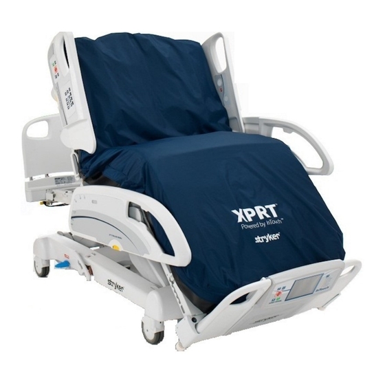
  • Seite 154: Produktabbildung

    Einführung PRODUKTABBILDUNG Kopfende Kopfende-Schaltkasten Deutsch HLR-Stecker Fußende Fußende-Schaltkasten Zurück zum Inhaltsverzeichnis 2950-109-005 REV B www.stryker.com...
  • Seite 155: Technische Daten

    Medizingerät: Klassifikation nur in Bezug auf Stromschlag und mechanische Gefahren, gemäß IEC 60601-1 CAN/CSA C22 .2 No . 601 . 1 .-M90 Elektromagnetische Verträglichkeit, erfüllt IEC 60601-1-2 (CISPR 11 Klassifikation als ISM-Gerät der Klasse A, Gruppe 1) Zurück zum Inhaltsverzeichnis www.stryker.com 2950-109-005 REV B...
  • Seite 156: Kontaktinformationen

    3800 E . Centre Avenue Portage, MI 49002 Deutsch Bei Anrufen beim Stryker-Kundendienst oder technischen Support bitte die Seriennummer (A) des jeweiligen Stryker-Produkts bereithalten . Die Seriennummer bei allen schriftlichen Mitteilungen angeben . IDENTIFIZIERUNG/ORT DER PRODUKTSERIENNUMMER Die Seriennummer (A) befindet sich auf dem Etikett auf der Vorderseite des Fußende-Schaltkastens und noch einmal (B) am Kopfende-Schaltkasten der Auflagefläche (siehe Abbildung 1) .
  • Seite 157: Zusammenfassung Der Sicherheitsvorkehrungen

    Den Patienten nicht unbeaufsichtigt lassen, während die Funktion „Turn-Assist“ (Wendehilfe) aktiviert ist . Andernfalls kann es zu schweren Verletzungen kommen . • Die therapeutische XPRT™-Auflagefläche deflatieren oder die Funktion „Max Inflate“ (Max . Inflation) verwenden, um sie vor einer HLR vollständig zu inflatieren . •...
  • Seite 158 Auflagefläche kann die Steuerung beschädigen und Gerätefehlfunktionen hervorrufen . • Um eine Fehlfunktion zu vermeiden, sollte die therapeutische XPRT™-Auflagefläche nicht neben oder übereinander gestapelt mit anderen Geräten verwendet werden (außer auf einem Bett) . Ist die Verwendung neben oder auf anderen Geräten erforderlich, sollte die therapeutische XPRT™-Auflagefläche beobachtet werden, um in der verwendeten...
  • Seite 159: Kontraindikationen

    Zusammenfassung der Sicherheitsvorkehrungen KONTRAINDIKATIONEN Stryker Medical fördert die klinische Beurteilung des Zustands von jedem Patienten und die geeignete Therapieanwendung durch das Pflegepersonal . Eine Luftunterstützungstherapie wird bei Patienten mit instabilen Frakturen, instabilen Rückenmarksverletzungen oder Patienten mit Traktion des Skeletts nicht empfohlen .
  • Seite 160: Einsatzvorbereitung

    • Um eine Fehlfunktion zu vermeiden, sollte die therapeutische XPRT™-Auflagefläche nicht neben oder übereinander gestapelt mit anderen Geräten verwendet werden (außer auf einem Bett) . Ist die Verwendung neben oder auf anderen Geräten erforderlich, sollte die therapeutische XPRT™- Auflagefläche beobachtet werden, verwendeten Konfiguration einen normalen Betrieb sicherzustellen .
  • Seite 161 Auflagefläche sicherstellen, mögliche Verletzungen vermeiden . Für optimale Ergebnisse das Stromkabel der therapeutischen XPRT™-Auflagefläche gut befestigen, um Beschädigungen am Kabel und Beeinträchtigungen des Bettrahmens und des Wiegesystems zu vermeiden . • Sicherstellen, dass das Stromkabel an der Bettseite entlang geführt wird und nicht aus dem Fußende des Bettes herausragt (siehe Abbildungen rechts) .
  • Seite 162: Einschalten Der Auflagefläche

    (Pause) . POSITION DER SEITENGITTER Die Position der Seitengitter ist ausschlaggebend für die Funktionalität der XPRT™-Auflagefläche . Bei entriegelten Seitengittern funktionieren mit Ausnahme der Rotationstherapie alle Therapien, einschließlich „Max Inflate“ (Max . Inflation), „Firmness“ (Härte) und „Turn Assist“ (Wendehilfe) . Wird ein Seitengitter während der Drehtherapie entriegelt, wird diese...
  • Seite 163: Klinische Funktionen Der Xprt™-Auflagefläche

    • Vor Beginn der Behandlung den Abschnitt „Kontraindikationen auf Seite 3-11 durchlesen . XPRT™ ist eine therapeutische Auflagefläche, die Patienten eine kontinuierliche Druckumverteilung bietet . Dies gilt bis zu einer Deutsch sicheren Arbeitslast von 226,8 kg . Die therapeutische XPRT™-Auflagefläche verfügt über die wählbaren Funktionen Rotation, Perkussion, Vibration, Wendehilfe und automatischer geringer Luftverlust .
  • Seite 164: Rotationstherapie

    Zur Gewährleistung der Patientensicherheit stets die Seitengitter des Bettes vor Beginn der Therapie anheben . • Bei der Verwendung der therapeutischen XPRT™-Auflagefläche auf einem mit Waage oder der Funktion „Bed Exit“ (Bettenausstieg) ausgestatteten Bettrahmen immer den Anweisungen des Herstellers bez . dieser Funktionen folgen, um mögliche Verletzungen zu vermeiden und einen ordnungsgemäßen Betrieb zu gewährleisten .
  • Seite 165: Start Der Rotationstherapie

    . • Alle Therapieparameter werden gespeichert, bis sie geändert oder zurückrückgesetzt werden . • Informationen zum Zurücksetzen der Parameter auf die Standardwerte finden Sie im Abschnitt „Erweiterte Einstellungen auf Seite 3-29 . Zurück zum Inhaltsverzeichnis www.stryker.com 2950-109-005 REV B 3-17...
  • Seite 166: Anpassen Der Aktiven Therapieparameter

    Sensoren korrekt ausgerichtet sind . ANHALTEN DER ROTATIONSTHERAPIE Die Schaltfläche „Stop“ (Anhalten) auswählen . Der Patient kehrt in die mittige Position zurück und die Rotation wird angehalten . Zurück zum Inhaltsverzeichnis 3-18 2950-109-005 REV B www.stryker.com...
  • Seite 167: Perkussionstherapie

    • Zur Gewährleistung der Patientensicherheit stets die Seitengitter des Bettes vor Beginn der Therapie anheben . • Bei der Verwendung der therapeutischen XPRT™-Auflagefläche auf einem mit Waage oder der Funktion „Bed Exit“ (Bettenausstieg) ausgestatteten Bettrahmen immer den Anweisungen des Herstellers bez . dieser Funktionen folgen, um mögliche Verletzungen zu vermeiden und einen ordnungsgemäßen Betrieb zu gewährleisten .
  • Seite 168: Anpassen Der Aktiven Therapieparameter

    Standardwerte finden Sie im Abschnitt „Erweiterte Einstellungen auf Seite 3-29 . • Die Schaltfläche für die Vibrationstherapie ist bei aktivierter Perkussion deaktiviert . ANHALTEN DER PERKUSSIONSTHERAPIE Die Schaltfläche „Stop“ (Anhalten) auswählen, damit die Perkussionstherapie angehalten wird . Zurück zum Inhaltsverzeichnis 3-20 2950-109-005 REV B www.stryker.com...
  • Seite 169: Vibrationstherapie

    • Zur Gewährleistung der Patientensicherheit stets die Seitengitter des Bettes vor Beginn der Therapie anheben . • Bei der Verwendung der therapeutischen XPRT™-Auflagefläche auf einem mit Waage oder der Funktion „Bed Exit“ (Bettenausstieg) ausgestatteten Bettrahmen immer den Anweisungen des Herstellers bez . dieser Funktionen folgen, um mögliche Verletzungen zu vermeiden und einen ordnungsgemäßen Betrieb zu gewährleisten .
  • Seite 170: Anpassen Der Aktiven Therapieparameter

    Standardwerte finden Sie im Abschnitt „Erweiterte Einstellungen auf Seite 3-29 . • Die Schaltfläche für die Perkussionstherapie ist bei aktivierter Vibration deaktiviert . ANHALTEN DER VIBRATIONSTHERAPIE Die Schaltfläche „Stop“ (Anhalten) auswählen, damit die Vibrationstherapie angehalten wird . Zurück zum Inhaltsverzeichnis 3-22 2950-109-005 REV B www.stryker.com...
  • Seite 171: Starten Der Funktion „Max Inflate" (Max. Inflation)

    Einstellungen . Zur Wiederaufnahme der Therapie muss „Start“ gedrückt werden . WARNUNG Die therapeutische XPRT™-Auflagefläche deflatieren oder die Funktion „Max Inflate“ (Max . Inflation) verwenden, um sie vor einer HLR vollständig zu inflatieren . Zurück zum Inhaltsverzeichnis www.stryker.com...
  • Seite 172: Anhalten Der Funktion „Max Inflate" (Max. Inflation)

    Funktion „Max Inflate“ (Max . Inflation) gestartet wird . Wird die Funktion „Max Inflate“ (Max . Inflation) angehalten, erscheint kurz eine Aufforderung zur Fortsetzung oder Wiederaufnahme der Therapie . Zurück zum Inhaltsverzeichnis 3-24 2950-109-005 REV B www.stryker.com...
  • Seite 173: Anpassen Der Härte Der Auflagefläche

    Die Einstellungen durch Erhöhen (+) oder Verringern (-) der Härte nach Bedarf anpassen . Die Schaltfläche „Ok“ auswählen . POSITIONIERUNG DES PATIENTEN Die Schultern des Patienten an der grafischen Darstellung auf der Auflageflächenseite ausrichten . Zurück zum Inhaltsverzeichnis www.stryker.com 2950-109-005 REV B 3-25...
  • Seite 174: Starten Der Funktion „Wendehilfe

    Bedienungsanleitung WARNUNG • Bei der Verwendung der therapeutischen XPRT™-Auflagefläche auf einem mit Waage oder der Funktion „Bed Exit“ (Bettenausstieg) ausgestatteten Bettrahmen immer den Anweisungen des Herstellers bez . dieser Funktionen folgen, um mögliche Verletzungen zu vermeiden und einen ordnungsgemäßen Betrieb zu gewährleisten .
  • Seite 175: Anhalten Der Funktion „Wendehilfe

    Die Rotations-, Perkussions- und Vibrationstherapie werden unterbrochen, wenn die Funktion „Turn Assist“ (Wendehilfe) gestartet wird . Wird die Funktion „Turn Assist“ (Wendehilfe) angehalten, erscheint kurz eine Aufforderung zur Fortsetzung oder Wiederaufnahme der Therapie . Zurück zum Inhaltsverzeichnis www.stryker.com 2950-109-005 REV B 3-27...
  • Seite 176: Verriegeln Aller Funktionen

    • Wird eine verriegelte Schaltfläche ausgewählt, erscheint die Meldung „Controls Locked“ (Steuerungen verriegelt) . ENTRIEGELN ALLER FUNKTIONEN Die Schaltfläche „Entriegeln“ auswählen . Die Meldung „Controls Unlocked“ (Steuerungen entriegelt) wird kurz angezeigt . Zurück zum Inhaltsverzeichnis 3-28 2950-109-005 REV B www.stryker.com...
  • Seite 177: Erweiterte Einstellungen

    • Nederlands (Niederländisch) Hinweis: • Die ausgewählte Sprache ist aktiv, bis eine andere Sprache ausgewählt wird . • Die ausgewählte Sprache wird nicht zurückgesetzt, wenn die Schaltfläche „Reset Parameters“ (Parameter zurücksetzen) ausgewählt wird . Zurück zum Inhaltsverzeichnis www.stryker.com 2950-109-005 REV B 3-29...
  • Seite 178: Zurücksetzen Der Therapie-Historie

    Historie) auswählen . Die Schaltfläche „Ok“ auswählen, damit die aktuelle Therapie-Historie gelöscht und auf null zurückgesetzt wird . Andernfalls die Schaltfläche „Cancel“ (Abbrechen) auswählen, um die aktuelle Therapie- Historie zu behalten . Zurück zum Inhaltsverzeichnis 3-30 2950-109-005 REV B www.stryker.com...
  • Seite 179: Zurücksetzen Der Parameter In Die Standardeinstellung

    Die Schaltfläche „Ok“ auswählen, damit alle Therapieparameter auf die Standardeinstellungen zurückgesetzt werden . Andernfalls die Schaltfläche „Cancel“ (Abbrechen) auswählen, um die aktuellen Parameter zu behalten . Hinweis: Die ausgewählte Sprache und die ausgewählten Alarmsignale werden nicht zurückgesetzt. Zurück zum Inhaltsverzeichnis www.stryker.com 2950-109-005 REV B 3-31...
  • Seite 180: Anzeigen Der Therapie-Historie

    Bedienungsanleitung ERWEITERTE EINSTELLUNGEN (FORTSETZUNG) ANZEIGEN DER THERAPIE-HISTORIE Die Schaltfläche auswählen . Die Schaltfläche „Therapy History“ (Therapie-Historie) auswählen . Deutsch Hinweis: Der Bildschirm „Therapy History“ (Therapie- Historie) wird 60 Sekunden lang angezeigt . Zurück zum Inhaltsverzeichnis 3-32 2950-109-005 REV B www.stryker.com...
  • Seite 181: Aktivierung Für Hlr

    Bedienungsanleitung AKTIVIERUNG FÜR HLR WARNUNG Die therapeutische XPRT™-Auflagefläche deflatieren oder die Funktion „Max Inflate“ (Max . Inflation) verwenden, um Deutsch sie vor einer HLR vollständig zu inflatieren . Siehe Abschnitt „Starten der Funktion „Max Inflate“ (Max . Inflation) Seite 3-23 .
  • Seite 182: Umlagerung Eines Patienten Auf Die Therapeutische Xprt™-Auflagefläche

    Funktion „Max Inflate“ (Max . Inflation) auszuschalten . WARNUNG • Die sichere Arbeitslast des Krankenhausbettrahmens bei einer Unterstützung von Patient und therapeutischer XPRT™- Auflagefläche nicht überschreiten, um das Risiko von Verletzungen bei Patient bzw . Anwender und von Geräteschäden zu verringern .
  • Seite 183: Patientenpflege

    Patientenverletzung kommen . Häufig nach dem Patienten sehen, um eine ordnungsgemäße Positionierung und Auflageflächeninflation zu gewährleisten . 12 . Die Schultern des Patienten an der grafischen Darstellung auf der Auflageflächenseite ausrichten . 13 . Die Seitengitter anheben und verriegeln . Zurück zum Inhaltsverzeichnis www.stryker.com 2950-109-005 REV B 3-35...
  • Seite 184: Platzierung Einer Bettpfanne

    • Die Auflagefläche nach jedem Patienten desinfizieren . Findet eine korrekte Desinfektion nicht statt, könnte es zu einer Kreuzkontamination und Infektion kommen . • Den Arzt verständigen, falls Rötung oder Hauterosion auftritt . Zurück zum Inhaltsverzeichnis 3-36 2950-109-005 REV B www.stryker.com...
  • Seite 185: Checkliste Für Vorbeugende Wartungsmaßnahmen

    ____ Schaumstoff-/Luftzellen weisen keine übermäßige Abnutzung (z . B . Risse) auf . Es wird empfohlen, die Zellen alle 6 Monate zu prüfen . Gegebenenfalls auswechseln . Seriennummer der Auflagefläche Bearbeiter:______________________________ Datum:__________________________________ Zurück zum Inhaltsverzeichnis www.stryker.com 2950-109-005 REV B 3-37...
  • Seite 186: Reinigung

    Auflagefläche kann die Steuerung beschädigen und Gerätefehlfunktionen hervorrufen . • Zum Entfernen von überschüssiger Flüssigkeit alle Oberflächen mit einem sauberen, trockenen Tuch abwischen . • Die therapeutische XPRT™-Auflagefläche nicht bügeln, chemisch reinigen oder im Wäschetrockner trocknen, da es dadurch zu Fehlfunktionen oder Schäden des Produkts kommt .
  • Seite 187: Vorgehensweise Bei Störungen Und Problemen

    Vertriebsvertretung von Stryker zur Einsendung zwecks Fehlerbewertung kontaktieren . 2) Wenn an keinem der Punkte Spannung vorliegt, die Netzplatine austauschen und die örtliche Vertriebsvertretung von Stryker zur Einsendung zwecks Fehlerbewertung kontaktieren . Wenn jetzt eine Stromzufuhr zur Auflagefläche besteht, diese wieder in Betrieb nehmen .
  • Seite 188 Stromkabel der Auflagefläche wieder in die Netzsteckdose stecken . Wenn jetzt eine Stromzufuhr zur Auflagefläche besteht, diese wieder in Betrieb nehmen . Den roten Anschluss auf korrekte Verbindung prüfen . Ist dies der Fall, mit einer anderen Steuerung testen . Zurück zum Inhaltsverzeichnis 3-40 2950-109-005 REV B www.stryker.com...
  • Seite 189: Mit Einem Lattenrost

    Produktetiketten XPRT Pulmonary Mattress STRYKER MEDICAL 3800 East Centre Ave. 2155/2156 (2950200002) Portage, MI 49002 USA 2011 VORSICHT Laut US-Bundesgesetz darf dieses Gerät Deutsch nur von einem Arzt oder auf ärztliche Anordnung verkauft werden. Schließen Sie das Gerät stets an eine geerdete...
  • Seite 190 ANFORDERUNGEN DES TECHNISCHEN MERKBLATTS 603 VOM CALIFORNIA BUREAU OF HOME FURNISHINGS. URETHANFOLIE INSTALLATIONSANWEISUNGEN FÜR DIE XPRT-MATRATZE Die 3 farbcodierten Anschlüsse am Die Handbedienung auf den Haltestift auf beiden Seiten des Die Matratze mit dem aufgedruckten Logo am Fußende-Schaltkasten mit den entsprechenden Fußende des Bettes auf die Liege äche legen.
  • Seite 191: Kurzgefasste Ersatzteilliste

    Die auf dieser Seite aufgeführten Ersatz- und Zubehörteile sind gegenwärtig alle zum Kauf erhältlich . Einige der in den Montagezeichnungen dieses Handbuchs gekennzeichneten Teile sind möglicherweise nicht einzeln zum Kauf erhältlich . Der Stryker-Kundendienst beantwortet unter der Nummer: 1-800-327-0770 (USA) gerne Fragen zu Erhältlichkeit und Preisen . Teilebezeichnung...
  • Seite 192: Wartungsinformationen

    Die sechs Schrauben, mit denen die Netzplatine an der Fußende-Schaltkastengruppe befestigt ist, mit einem Phillips- Schraubendreher entfernen . Die Netzplatine abnehmen und die örtliche Vertriebsvertretung von Stryker zur Einsendung zwecks Fehlerbewertung kontaktieren . Das Verfahren umkehren, um die neue Netzplatine zu installieren .
  • Seite 193: Austausch Der Fußende-Schaltkastenpumpe

    Kopfschrauben (D) entfernen, mit denen die Pumpenbaugruppe an der Unterseite des Fußende- Schaltkastens befestigt ist (siehe Abbildung 3) . Die Kopfschrauben für den Wiedereinbau aufbewahren . Abbildung 1 Abbildung 2 Abbildung 3 Zurück zum Inhaltsverzeichnis www.stryker.com 2950-109-005 REV B 3-45...
  • Seite 194 (siehe Abbildung 1) . 18 . Das Fußteil der Auflagefläche wieder nach unten klappen . 19 . Die Funktion der Auflagefläche prüfen, bevor sie wieder in Betrieb genommen wird . Abbildung 7 Zurück zum Inhaltsverzeichnis 3-46 2950-109-005 REV B www.stryker.com...
  • Seite 195: Austausch Der Cpu-Platine Des Kopfende-Schaltkastens

    . Die acht Schrauben, mit denen die CPU-Platine am Kopfende-Schaltkasten befestigt ist, entfernen und die örtliche Vertriebsvertretung von Stryker zur Einsendung zwecks Fehlerbewertung kontaktieren . 10 . Das Verfahren umkehren, um die neue CPU-Platine zu installieren .
  • Seite 196: Schrittschaltmotor / Drehschiebergruppe Des Kopfende-Schaltkastens

    Den neuen Schrittschaltmotor / die neue Drehschiebergruppe installieren und die Schritte umkehren . 10 . Das Stromkabel der Auflagefläche in die Netzsteckdose stecken und die Funktion testen, bevor sie wieder in Betrieb genommen wird . Zurück zum Inhaltsverzeichnis 3-48 2950-109-005 REV B www.stryker.com...
  • Seite 197: Austauschkit Für Die Zellgruppe

    . Siehe Abbildung 1 . Abbildung 1 Die vorhandenen 90-Grad-Nippel vom Kopfende-Schaltkasten abnehmen und an allen vier Stellen gegen neue 90-Grad-Nippel austauschen . Zur Ausrichtung siehe Abbildung 2 . Abbildung 2 Zurück zum Inhaltsverzeichnis www.stryker.com 2950-109-005 REV B 3-49...
  • Seite 198 Die Schläuche jeweils etwas über den beiden am Kopfende-Schaltkasten befindlichen 90-Grad-Nippeln einschneiden . Siehe Abbildung 4 . Abbildung 4 Die vorhandenen 90-Grad-Nippel vom Kopfende-Schaltkasten abnehmen und an beiden Stellen gegen neue 90-Grad-Nippel austauschen . Zur Ausrichtung siehe Abbildung 5 . Abbildung 5 Zurück zum Inhaltsverzeichnis 3-50 2950-109-005 REV B www.stryker.com...
  • Seite 199: Installation Der Neuen Zellgruppe

    Hinweis: Zum Herunterklappen der Auflagefläche in die ursprüngliche flache Position werden zwei Personen benötigt . Den Zellhaltegurt von der Zellgruppe nahe dem Fußende (siehe Abbildung 6) ausschnappen . 10 . Die Zellgruppe entfernen und die örtliche Vertriebsvertretung von Stryker zur Einsendung zwecks Fehlerbewertung kontaktieren .
  • Seite 200: Die Schläuche An Zwei Neue 90-Grad-Nippel

    Schläuche eingeführt sind . Siehe Abbildung 10 . Das Kopfende der Auflagefläche in die ursprüngliche flache Position herunterklappen . Hinweis: Zum Zurückklappen des Schaumstoffunterbaus und des Kopfende-Schaltkastens werden zwei Personen benötigt . Abbildung 10 Zurück zum Inhaltsverzeichnis 3-52 2950-109-005 REV B www.stryker.com...
  • Seite 201 14 . Die Auflagefläche in den Wartungsmodus versetzen . (Bildschirm sperren, Schaltfläche „Percussion“ (Perkussion) 5 Sekunden lang halten, Schaltfläche „Rotation“ 5 Sekunden lang halten, Schaltfläche „Start“ drücken) . 15 . Einen Diagnosetest durchführen, um sicherzustellen, dass die Auflagefläche einwandfrei funktioniert . Zurück zum Inhaltsverzeichnis www.stryker.com 2950-109-005 REV B 3-53...
  • Seite 202: Aufrufen Des Wartungsbildschirms

    Deutsch Eine Handbedienung an den schwarzen Anschluss des Fußende-Schaltkastens anschließen . Hinweis: XPRT-Auflageflächen, die in InTouch 1 .x und 3 .x integriert sind, benötigen keine Handbedienung, um den Wartungsbildschirm aufzurufen . XPRT-Auflageflächen mit der Softwareversion 2 .x benötigen jedoch eine Handbedienung, um die Wartungsinformationen aufzurufen .
  • Seite 203 Ergebnis des Diagnosetests . Zeigt bis zur Durchführung des Diagnosetests keine Werte an . Die Werte werden bei Durchführung der Tests aktualisiert . Status für Übertemperatur . Wartungs-/Fehlerprotokoll Zeigt Wartungscodes und Beschreibungen an . Auf die Schaltfläche nach oben oder nach unten drücken, um die Ereignis-/Fehlerliste durchzublättern . Zurück zum Inhaltsverzeichnis www.stryker.com 2950-109-005 REV B 3-55...
  • Seite 204: Funktionen Des Wartungsbildschirms

    . Diese Funktion ist nur für Herstellungszwecke (,Manufacturing‘) vorgesehen . Auf die Schaltfläche „Restart Log“ (Protokoll neu starten) drücken, um Ereignisinformationen von der CPU zu aktualisieren . Beim Austauschen einer Steuerung verwenden . Zurück zum Inhaltsverzeichnis 3-56 2950-109-005 REV B www.stryker.com...
  • Seite 205 Auf die Schaltfläche „Reset Service Error/Log“ (Wartungs-/Fehlerprotokoll zurücksetzen) drücken, um das Wartungsfehlerprotokoll zurückzusetzen . Deutsch Auf die Schaltfläche „Cancel“ (Abbrechen) drücken, um die auf dem Wartungsbildschirm ausgeführten Funktionen abzubrechen und zum Therapiemenü zurückzukehren . Zurück zum Inhaltsverzeichnis www.stryker.com 2950-109-005 REV B 3-57...
  • Seite 206: Wartungscodes

    TB6 der Platine eingerastet ist . CPR_Both Beide HLR-Stecker werden Prüfen, ob die HLR-Stecker vollständig nicht erkannt . eingerastet und eingeschnappt sind . Prüfen, ob der Anschluss vollständig in TB6 der Platine eingerastet ist . Zurück zum Inhaltsverzeichnis 3-58 2950-109-005 REV B www.stryker.com...
  • Seite 207 Schaltkasten . Temp . > 60 °C . Anzeige prüfen . der Meldung „Auto . Overload Caused a Die Spannung des Power Shutdown” (Automatische Perkussionsmotorriemens prüfen . Überlastung führte zu Stromabschaltung) . Das Verbindungsstangenlager prüfen . Zurück zum Inhaltsverzeichnis www.stryker.com 2950-109-005 REV B 3-59...
  • Seite 208 Draht (TB9) von weniger als 0,2 V Gleichstrom, wenn die Markierung auf den Sensor ausgerichtet ist, und mehr als 4,0 V Gleichstrom, wenn diese nicht ausgerichtet ist, prüfen . Den Sensor, falls erforderlich, austauschen . Zurück zum Inhaltsverzeichnis 3-60 2950-109-005 REV B www.stryker.com...
  • Seite 209 HLR-Stecker ziehen und den HLR- Limitschalter eingerastet lassen . geknickten Zufuhrschlauch der Auflagefläche prüfen und diesen, falls erforderlich, gegen einen drahtverstärkten Zufuhrschlauch Klemmen austauschen . Wandverschraubung Fußende- Schaltkasten auf Verstopfungen prüfen und, falls erforderlich, austauschen . Zurück zum Inhaltsverzeichnis www.stryker.com 2950-109-005 REV B 3-61...
  • Seite 210 In einer Luftzelle, die nicht gefüllt sein Der Drehschieber hielt an der falschen sollte, wurde ein übermäßiger Druck Position an und füllt die falsche Zelle . festgestellt . Schläuche korrekte Verbindungen prüfen . Zurück zum Inhaltsverzeichnis 3-62 2950-109-005 REV B www.stryker.com...
  • Seite 211 Leckweg zwischen Rotationszellen werden gleichzeitig Rotationszellen prüfen . gefüllt . Der Alarm ist empfindlicher, wenn Rotationsgeschwindigkeit sehr niedrig eingestellt wurde, der Patient sich bewegt oder kein Patient auf der Auflagefläche liegt . Zurück zum Inhaltsverzeichnis www.stryker.com 2950-109-005 REV B 3-63...
  • Seite 212 Das System hat Strom verloren Dies ist keine Fehlermeldung, sondern und einen Neustart durchgeführt . eher ein Hinweis, dass das System Strom verloren hat und der Strom wieder zugeführt wurde . Deutsch Zurück zum Inhaltsverzeichnis 3-64 2950-109-005 REV B www.stryker.com...
  • Seite 213: Alarme / Fehler

    Rotationsblasenkreislauf festgestellt . RIGHT_SURFACE_LEAK Durch Diagnosetest Leck im Rotationsblasenkreislauf festgestellt . LEFT_PERCUSSION_LEAK Durch Diagnosetest Leck im Perkussionsblasenkreislauf festgestellt . RIGHT_PERCUSSION_LEAK Durch Diagnosetest Leck im Perkussionsblasenkreislauf festgestellt . INVALID_COMMAND Auflageflächensteuerung hat ungültigen Befehl erhalten . Zurück zum Inhaltsverzeichnis www.stryker.com 2950-109-005 REV B 3-65...
  • Seite 214: Recycling Passports

    Recycling Passports Assembly Part number: 2950-047-000 (Reference Only) Head Box Assembly Deutsch Item Recycling/Material Code Important Information (2950-001-225) Valve Solenoid 24 VDC (2950-001-224) Sensor Solenoid 24 VDC (2950-101-223) PCB, Main Control Board Assembly Zurück zum Inhaltsverzeichnis 3-66 2950-109-005 REV B www.stryker.com...
  • Seite 215 Recycling Passports Assembly Part number: 2950-003-007 (Reference Only) Deutsch Foot Box Assembly Item Recycling/Material Code Important Information (2950-001-116) Power Supply Board (2950-001-119) Transformer Assembly (2950-001-123) EMI Power Line Filter Zurück zum Inhaltsverzeichnis www.stryker.com 2950-109-005 REV B 3-67...
  • Seite 216: Emv-Angaben

    Anleitungen und Herstellererklärung – Elektromagnetische Störfestigkeit Die XPRT™-Auflagefläche ist für den Gebrauch in der nachfolgend spezifizierten elektromagnetischen Umgebung vorgesehen . Der Kunde bzw . der Anwender der XPRT™-Auflagefläche hat dafür zu sorgen, dass sie in einer solchen Umgebung verwendet wird .
  • Seite 217 Empfohlene Trennabstände zwischen tragbaren und mobilen HF- Kommunikationsgeräten und der XPRT™-Auflagefläche. Die XPRT™-Auflagefläche ist für den Gebrauch in einer elektromagnetischen Umgebung vorgesehen, in der Störungen durch abgestrahlte HF unter Kontrolle sind . Der Kunde bzw . der Anwender der XPRT™-Auflagefläche kann dazu beitragen, elektromagnetische Störungen durch Einhalten eines Mindestabstands zwischen den tragbaren und...
  • Seite 218 HF-Sender verursachten elektromagnetischen Strahlung sollte deshalb eine elektromagnetische Untersuchung des Standorts erfolgen . Wenn die gemessene Feldstärke an dem Standort, an dem die XPRT™-Auflagefläche eingesetzt wird, die oben erwähnten Grenzwerte für die Hochfrequenz übersteigt, sollte der Normalbetrieb der XPRT™- Auflagefläche überprüft werden .
  • Seite 219: Anleitungen Und Herstellererklärung - Elektromagnetische Emissionen

    Anleitungen und Herstellererklärung – Elektromagnetische Emissionen -Auflagefläche ist für den Gebrauch in der nachfolgend spezifizierten elektromagnetischen XPRT™ Umgebung vorgesehen . Der Kunde bzw . der Anwender der XPRT™-Auflagefläche hat dafür zu sorgen, dass sie in einer solchen Umgebung verwendet wird . Emissionstest Konformität...
  • Seite 220: Garantie

    Bereitstellung von Ersatzteilen und Arbeitskräften für – nach seiner Wahl – die Reparatur oder den Ersatz von Produkten, die Stryker nach alleinigem Ermessen für defekt befindet . Auf Ersuchen von Stryker müssen Produkte bzw . Teile, für die ein Garantieanspruch erhoben wird, auf eigene Kosten an das Werk zurückgeschickt werden . Missbräuchliche Verwendung Deutsch des Produkts oder Änderungen bzw .
  • Seite 221 De weergegeven taal wijzigen . . . . . . . . . . . . . . . . . . . . . . . . . . . . . . . . . . . . . . . . . . . . . . . . . . . . . . . . . . 4-29 Terug naar de inhoudsopgave www.stryker.com 2950-109-005 REV B...
  • Seite 222 Een patiënt vanaf het XPRT™ therapeutische steunoppervlak verplaatsen . . . . . . . . . . . . . . . . .
  • Seite 223: Symbolen En Definities

    . Zie gebruiksaanwijzing Modelnummer Fabrikant Alleen met een vochtige doek afnemen 10% bleekwater Niet in de droogtrommel drogen Niet strijken Niet chemisch reinigen Helemaal aan de lucht laten drogen Terug naar de inhoudsopgave www.stryker.com 2950-109-005 REV B...
  • Seite 224: Definitie Van Waarschuwing / Let Op / Opmerking

    . OPMERKING Verstrekt speciale informatie die het onderhoud vergemakkelijkt of belangrijke instructies verduidelijkt . Terug naar de inhoudsopgave 2950-109-005 REV B www.stryker.com...
  • Seite 225: Inleiding

    De XPRT is niet geschikt voor gebruik in aanwezigheid van een brandbaar anesthesiemengsel met zuurstofrijke lucht of lucht met lachgas . De XPRT is ontworpen voor een levensduur van het product van vijf (5) jaar en drie (3) jaar voor de hoezen, bij normaal gebruik, onder normale omstandigheden, en bij correct periodiek onderhoud zoals beschreven in de onderhoudshandleiding voor elk apparaat .
  • Seite 226: Afbeelding Van Het Product

    Inleiding AFBEELDING VAN HET PRODUCT Hoofdeinde Regelkast voor hoofdeinde Nederlands Reanimatiestop Regelkast voor Voeteneinde voeteneinde Terug naar de inhoudsopgave 2950-109-005 REV B www.stryker.com...
  • Seite 227: Specificaties

    IEC 60601-1 CAN/CSA C22 .2 nr . 601 . 1 -M90 . Elektromagnetische compatibiliteit, voldoet aan IEC 60601-1-2 (CISPR 11 geclassificeerd als apparatuur van klasse A, groep 1 ISM) Terug naar de inhoudsopgave www.stryker.com 2950-109-005 REV B...
  • Seite 228: Contactgegevens

    3800 E . Centre Avenue Portage, MI 49002 Zorg dat u het serienummer (A) van uw Stryker-product bij de hand hebt wanneer u de klantenservice of technische ondersteuning van Stryker belt . Vermeld het serienummer in al uw correspondentie .
  • Seite 229: Samenvatting Van De Veiligheidsmaatregelen

    Verminder het risico van letsel bij de patiënt of de gebruiker en beschadiging van de apparatuur door de veilige werkbelasting van het frame van het ziekenhuisbed niet te overschrijden wanneer het frame zowel de patiënt als het XPRT™ therapeutische steunoppervlak draagt .
  • Seite 230 Om mogelijk letsel te voorkomen, dient u na plaatsing van het steunoppervlak de werking van het weegsysteem te controleren . Voor de beste resultaten dient u het netsnoer van het XPRT™ therapeutische steunoppervlak vast te zetten om te voorkomen dat het netsnoer wordt beschadigd en dit het frame van het bed en het weegsysteem in de weg staat .
  • Seite 231: Contra-Indicaties

    Samenvatting van de veiligheidsmaatregelen CONTRA-INDICATIES Stryker Medical is voorstander van de klinische beoordeling van de gesteldheid van elke patiënt en de toepassing van de juiste hulp door de zorgverlener . Gebruik van een luchtmatras wordt niet aanbevolen voor patiënten met instabiele fracturen of instabiel ruggenmergletsel of die in tractie liggen .
  • Seite 232: Het Steunoppervlak Installeren

    (behalve een bed) worden gebruikt . Als gebruik naast of gestapeld met andere apparatuur nodig is, moet het XPRT™ therapeutische steunoppervlak worden geobserveerd om te verifiëren dat het normaal werkt in de configuratie waarin het zal worden gebruikt .
  • Seite 233 . Voor de beste resultaten dient u het netsnoer van het XPRT™ therapeutische steunoppervlak vast te zetten om te voorkomen dat het netsnoer wordt beschadigd en dit het frame van het bed en het weegsysteem in de weg staat .
  • Seite 234: Het Steunoppervlak Opstarten

    (uit) of PAUSED (gepauzeerd) laat zien . STAND ONRUSTHEKKEN De stand van de onrusthekken bepaalt de functionaliteit van de XPRT™ . Alle behandelingen, waaronder Max Inflate (maximaal oppompen), Firmness (stevigheid) en Turn Assist (hulp bij draaien), werken als de onrusthekken losgezet zijn, met uitzondering van de rotatiehulp.
  • Seite 235: Te Gebruiken Hulpen

    LAAG LUCHTVERLIES De XPRT™ zorgt voor een continue luchtstroom door het steunoppervlak met meerdere zones . LAL (laag luchtverlies) helpt bij de behandeling van het microklimaat van de huid op plaatsen waar de huid contact maakt met het steunoppervlak .
  • Seite 236: Voorbereiden Op Rotatiehulp

    Bevestig de banden van het steunoppervlak altijd aan het bedframe om te voorkomen dat het steunoppervlak verschuift en de patiënt hierdoor letsel oploopt . • Risico van letsel . Gebruik van het XPRT therapeutische steunoppervlak voor slachtoffers van een beroerte mag uitsluitend op voorschrift van een arts gebeuren . •...
  • Seite 237: Rotatiehulp Starten

    • Alle parameters voor de hulp worden opgeslagen totdat ze gewijzigd of gereset worden . • Om de parameters te resetten naar de standaardwaarden, raadpleegt u ‘Geavanceerde instellingen’ op pagina 4-29 Terug naar de inhoudsopgave www.stryker.com 2950-109-005 REV B 4-17...
  • Seite 238: De Actieve Parameters Voor De Hulp Aanpassen

    . ROTATIEHULP STOPPEN Selecteer de toets “Stop” (stoppen) . De patiënt wordt weer in de middelste stand geplaatst en de rotatie stopt . Terug naar de inhoudsopgave 4-18 2950-109-005 REV B www.stryker.com...
  • Seite 239: Percussiehulp Starten

    Bevestig de banden van het steunoppervlak altijd aan het bedframe om te voorkomen dat het steunoppervlak verschuift en de patiënt hierdoor letsel oploopt . • Risico van letsel . Gebruik van het XPRT therapeutische steunoppervlak voor slachtoffers van een beroerte mag uitsluitend op voorschrift van een arts gebeuren . •...
  • Seite 240: De Actieve Parameters Voor De Hulp Aanpassen

    4-29 . • De toets voor de vibratiehulp is niet actief terwijl Percussion (percussie) actief is . PERCUSSIEHULP STOPPEN Selecteer de toets “Stop” (stoppen), waarna de percussiehulp wordt gestopt . Terug naar de inhoudsopgave 4-20 2950-109-005 REV B www.stryker.com...
  • Seite 241: Vibratiehulp Starten

    Bevestig de banden van het steunoppervlak altijd aan het bedframe om te voorkomen dat het steunoppervlak verschuift en de patiënt hierdoor letsel oploopt . • Risico van letsel . Gebruik van het XPRT therapeutische steunoppervlak voor slachtoffers van een beroerte mag uitsluitend op voorschrift van een arts gebeuren . •...
  • Seite 242: De Actieve Parameters Voor De Hulp Aanpassen

    4-29 . • De toets voor de percussiehulp is niet actief terwijl Vibration (vibratie) actief is . VIBRATIEHULP STOPPEN Selecteer de toets “Stop” (stoppen), waarna de vibratiehulp wordt gestopt . Terug naar de inhoudsopgave 4-22 2950-109-005 REV B www.stryker.com...
  • Seite 243: Max Inflate (Maximaal Oppompen) Starten

    . Er moet op “Start” (starten) worden gedrukt om de hulp te hervatten . WAARSCHUWING Laat het XPRT™ therapeutische steunoppervlak leeglopen of gebruik Max Inflate (maximaal oppompen) om het steunoppervlak volledig op te pompen voordat u met reanimatie begint . Terug naar de inhoudsopgave www.stryker.com...
  • Seite 244: Max Inflate (Maximaal Oppompen) Stoppen

    Max Inflate (maximaal oppompen) wordt gestart . Wanneer Max Inflate (maximaal oppompen) wordt gestopt, wordt er kortstondig een prompt gegeven om door te gaan of om de hulp te hervatten . Nederlands Terug naar de inhoudsopgave 4-24 2950-109-005 REV B www.stryker.com...
  • Seite 245: Hardheid Steunoppervlak Aanpassen

    (+) of te verkleinen (-) . Selecteer de toets “Ok” (OK) . PATIËNT POSITIONEREN Breng de schouders van de patiënt op één lijn met de grafische indicator op de zijkant van het steunoppervlak . Terug naar de inhoudsopgave www.stryker.com 2950-109-005 REV B 4-25...
  • Seite 246: Turn Assist (Hulp Bij Draaien) Starten

    Om mogelijk letsel te voorkomen, dient u na plaatsing van het steunoppervlak de werking van het weegsysteem te controleren . Voor de beste resultaten dient u het netsnoer van het XPRT™ therapeutische steunoppervlak vast te zetten om te voorkomen dat het netsnoer wordt beschadigd en dit het frame van het bed en het weegsysteem in de weg staat .
  • Seite 247: Turn Assist (Hulp Bij Draaien) Stoppen

    Turn Assist (hulp bij draaien) wordt gestart . Wanneer Turn Assist (hulp bij draaien) wordt gestopt, wordt er kortstondig een prompt gegeven om door te gaan of om de hulp te hervatten . Terug naar de inhoudsopgave www.stryker.com 2950-109-005 REV B 4-27...
  • Seite 248: Alle Functies Vergrendelen

    Wanneer er een vergrendelde toets wordt geselecteerd, verschijnt de melding “Controls Locked” (regelaars vergrendeld) . Nederlands ALLE FUNCTIES ONTGRENDELEN Selecteer de ontgrendelingstoets . De melding “Controls Unlocked” (regelaars ontgrendeld) wordt kortstondig weergegeven . Terug naar de inhoudsopgave 4-28 2950-109-005 REV B www.stryker.com...
  • Seite 249: Geavanceerde Instellingen

    Opmerking: • De geselecteerde taal is actief totdat een andere taal wordt geselecteerd . • De geselecteerde taal wordt niet gereset wanneer de toets “Reset Parameters” (parameters resetten) wordt geselecteerd . Terug naar de inhoudsopgave www.stryker.com 2950-109-005 REV B 4-29...
  • Seite 250: Therapy History (Geschiedenis Van Hulp) Resetten

    Select de toets “Ok” (OK) . De huidige geschiedenis van de hulp wordt gewist en op nul teruggesteld . Of selecteer “Cancel” (annuleren) om de geschiedenis van de huidige hulp te bewaren . Terug naar de inhoudsopgave 4-30 2950-109-005 REV B www.stryker.com...
  • Seite 251: Parameters Op De Standaardinstellingen Resetten

    Selecteer de toets “Ok” (OK) om alle parameters voor de hulp te resetten naar de standaardinstellingen . Of selecteer “Cancel” (annuleren) om de huidige parameters te bewaren . Opmerking: De geselecteerde taal en alarmtonen worden niet gereset . Terug naar de inhoudsopgave www.stryker.com 2950-109-005 REV B 4-31...
  • Seite 252: Geschiedenis Van De Hulp Bekijken

    GESCHIEDENIS VAN DE HULP BEKIJKEN Selecteer Selecteer de toets “Therapy History” (geschiedenis van de hulp) . Opmerking: Het scherm Therapy History (geschiedenis van de hulp) wordt 60 seconden lang weergegeven . Nederlands Terug naar de inhoudsopgave 4-32 2950-109-005 REV B www.stryker.com...
  • Seite 253: Reanimatieactivering

    Gebruikshandleiding REANIMATIEACTIVERING WAARSCHUWING Laat het XPRT™ therapeutische steunoppervlak leeglopen of gebruik Max Inflate (maximaal oppompen) om het steunoppervlak volledig op te pompen voordat u met reanimatie begint . Raadpleeg ‘Max Inflate (maximaal oppompen) starten’ pagina 4-23 Om reanimatie te activeren, trekt u aan de linker- of...
  • Seite 254: Een Patiënt Naar Het Xprt™ Therapeutische Steunoppervlak Verplaatsen

    Verminder het risico van letsel bij de patiënt of de gebruiker en beschadiging van de apparatuur door de veilige werkbelasting van het frame van het ziekenhuisbed niet te overschrijden wanneer het frame zowel de patiënt als het XPRT™ therapeutische steunoppervlak draagt .
  • Seite 255: Verpleegkundige Zorg

    12 . Breng de schouders van de patiënt op één lijn met de grafische indicator op de zijkant van het steunoppervlak . 13 . Breng de onrusthekken omhoog en vergrendel ze . Terug naar de inhoudsopgave www.stryker.com 2950-109-005 REV B 4-35...
  • Seite 256: Plaatsen Van De Ondersteek

    Desinfecteer het steunoppervlak tussen patiënten door . Als het steunoppervlak niet naar behoren wordt gedesinfecteerd, kunnen kruisbesmetting en infectie optreden . • Raadpleeg een arts bij het optreden van erytheem of decubitus . Terug naar de inhoudsopgave 4-36 2950-109-005 REV B www.stryker.com...
  • Seite 257: Checklist Voor Preventief Onderhoud

    ____ Het schuimrubber/de luchtcellen vertonen geen overmatige slijtage (bijv . barsten) . Aanbevolen wordt de cellen om de 6 maanden te controleren . Vervang indien nodig . Serienummer steunoppervlak Ingevuld door:_________________________ Datum________________________________ Terug naar de inhoudsopgave www.stryker.com 2950-109-005 REV B 4-37...
  • Seite 258: Reiniging

    Neem alle oppervlakken af met een schone, droge doek om eventueel overtollig vocht te verwijderen . • Het XPRT™ therapeutische steunoppervlak mag niet worden gestreken, chemisch gereinigd of in een droogtrommel worden gedroogd, omdat dit storing en beschadiging van het product zal veroorzaken .
  • Seite 259: Problemen Oplossen

    1) Als er op geen van de punten spanning aanwezig is, controleer dan connector J2 op 26 VAC . Als er geen spanning is, vervang dan de transformator en neem contact op met uw plaatselijke Stryker- vertegenwoordiger om de transformator op storing te laten onderzoeken .
  • Seite 260 . Controleer of de rode connector goed is aangesloten . As hij goed is aangesloten, test dan of een ander bedieningspaneel wel werkt . Terug naar de inhoudsopgave 4-40 2950-109-005 REV B www.stryker.com...
  • Seite 261: Productlabels

    Productlabels XPRT Pulmonary Mattress STRYKER MEDICAL 3800 East Centre Ave. 2155/2156 (2950200002) Portage, MI 49002 USA 2011 LET OP Krachtens de federale wetten van de Verenigde Staten mag dit apparaat uitsluitend door of op voorschrift van een arts worden verkocht. Sluit ten behoeve...
  • Seite 262 603 VAN CALIFORNIA BUREAU OF HOME FURNISHINGS. URETHAANFILM INSTRUCTIES VOOR INSTALLATIE VAN DE XPRT-MATRAS Sluit de 3 connectors met kleurcodering van de regelkast Druk het bedieningspaneel op de borgpen aan een van Plaats de matras op de matrasdrager, met het voor het voeteneinde aan op de overeenkomstige gedrukte logo aan het hoofdeinde van het bed.
  • Seite 263: Naslaglijst Vervangingsonderdelen

    De op deze pagina vermelde onderdelen en accessoires zijn momenteel alle leverbaar . Sommige van de op de montagetekeningen in deze handleiding geïdentificeerde onderdelen zijn mogelijk niet afzonderlijk leverbaar . Bel de klantenservice van Stryker in de VS: 1-800-327-0770 voor beschikbaarheid en prijzen .
  • Seite 264: Service-Informatie

    Verwijder met behulp van een kruiskopschroevendraaier de zes schroeven waarmee de printplaat op de regelkast voor het voeteneinde wordt vastgehouden . Verwijder de printplaat en neem contact op met uw plaatselijke Stryker-vertegenwoordiger om de printplaat op storing te laten onderzoeken .
  • Seite 265: De Pomp In De Regelkast Voor Het Voeteneinde Vervangen

    (D) waarmee de pomp aan de onderzijde van de regelkast voor het voeteneinde is vastgezet (afbeelding 3) . Bewaar de bouten voor het terugplaatsen . Afbeelding 1 Afbeelding 2 Afbeelding 3 Terug naar de inhoudsopgave www.stryker.com 2950-109-005 REV B 4-45...
  • Seite 266 3 (zie afbeelding 1) . 18 . Sla het voeteneinde van het steunoppervlak weer terug . 19 . Test de werking van het steunoppervlak voordat dit weer in gebruik wordt genomen . Afbeelding 7 Terug naar de inhoudsopgave 4-46 2950-109-005 REV B www.stryker.com...
  • Seite 267: Printplaat Van De Cve In De Regelkast Voor Het Hoofdeinde Vervangen

    . Verwijder met behulp van een kruiskopschroevendraaier de acht schroeven waarmee de printplaat van de CVE aan de regelkast voor het hoofdeinde vastzit en neem contact op met uw plaatselijke Stryker-vertegenwoordiger om de printplaat op storing te laten onderzoeken .
  • Seite 268: Stappenmotor-/Draaiklepassemblage Van De Regelkast Voor Het Hoofdeinde

    Installeer de nieuwe stappenmotor/draaiklep-assemblage en voer de stappen in omgekeerde volgorde uit . 10 . Sluit het netsnoer van het steunoppervlak aan op de voedingsbron en test de werking van het steunoppervlak alvorens dit opnieuw in gebruik te nemen . Terug naar de inhoudsopgave 4-48 2950-109-005 REV B www.stryker.com...
  • Seite 269: Vervangingskit Voor Cellenassemblage

    Verwijder de aanwezige 90-graden fittingen van de regelkast voor het hoofdeinde en vervang deze door nieuwe 90-graden fittingen, op vier plaatsen . Raadpleeg afbeelding 2 voor de oriëntatie . Afbeelding 2 Terug naar de inhoudsopgave www.stryker.com 2950-109-005 REV B 4-49...
  • Seite 270 Verwijder de aanwezige 90-graden fittingen van de regelkast voor het hoofdeinde en vervang deze door nieuwe 90-graden fittingen, op twee plaatsen . Raadpleeg afbeelding 5 voor de oriëntatie . Afbeelding 5 Terug naar de inhoudsopgave 4-50 2950-109-005 REV B www.stryker.com...
  • Seite 271: Installatie Van Nieuwe Cellenassemblage

    Opmerking: Er zijn twee mensen voor nodig om het steunoppervlak in zijn oorspronkelijke platte stand terug te zetten . Maak de cellensluitriem los van de cellenassemblage vlak bij het voeteneinde zoals getoond in afbeelding 6 . 10 . Verwijder de cellen en neem contact op met uw plaatselijke Stryker-vertegenwoordiger om de cellen op storing te laten onderzoeken .
  • Seite 272 Zet het hoofdeinde van het steunoppervlak weer terug in zijn oorspronkelijke platte stand . Opmerking: Er zijn twee mensen voor nodig om de schuimrubber onderlegger en de regelkast voor het Afbeelding 10 hoofdeinde terug te slaan . Terug naar de inhoudsopgave 4-52 2950-109-005 REV B www.stryker.com...
  • Seite 273 14 . Zet het steunoppervlak in de servicemodus . (Lock Screen [scherm vergrendelen], houd Percussion [percussie] 5 seconden ingedrukt, houd Rotation [rotatie] 5 seconden ingedrukt, druk op Start [start] . ) 15 . Voer een diagnostische test uit om te verifiëren dat het steunoppervlak goed werkt . Terug naar de inhoudsopgave www.stryker.com 2950-109-005 REV B 4-53...
  • Seite 274: Het Servicescherm Openen

    Opmerking: Bij XPRT steunoppervlakken die zijn geïntegreerd in InTouch 1 .x en 3 .x is geen bedieningspaneel vereist om het servicescherm te openen . Bij XPRT met softwareversies 2 .x is echter het bedieningspaneel vereist om de service-informatie te openen .
  • Seite 275 . De waarden worden bijgewerkt terwijl de tests worden uitgevoerd . Overtemperatuurstatus . Service-/foutenlog . Geeft servicecodes en beschrijvingen weer . Druk op de toetsen omhoog of omlaag om de lijst met voorvallen/fouten door te nemen . Terug naar de inhoudsopgave www.stryker.com 2950-109-005 REV B 4-55...
  • Seite 276: Functies Op Het Servicescherm

    . Druk op de toets “Restart Log” (log opnieuw starten) om de voorvalleninformatie van de CVE bij te werken . Gebruik dit wanneer u een bedieningspaneel vervangt . Terug naar de inhoudsopgave 4-56 2950-109-005 REV B www.stryker.com...
  • Seite 277 . Nederlands Druk op de toets “Cancel” (annuleren) om alle functies op het servicescherm te annuleren en terug te keren naar het hulpmenu . Terug naar de inhoudsopgave www.stryker.com 2950-109-005 REV B 4-57...
  • Seite 278: Servicecodes

    TB6 . CPR_Both Geen van beide reanimatiestoppen Controleer of de reanimatiestoppen goed op worden gedetecteerd . hun plaats zitten en aangedrukt zijn . Controleer connector helemaal aangesloten is op printplaat TB6 . Terug naar de inhoudsopgave 4-58 2950-109-005 REV B www.stryker.com...
  • Seite 279 Controleer de spanning van de riem van de Toont melding “Auto . Overload Caused percussiemotor . a Power Shutdown” (automatische Controleer het lager van de verbindingsstang . overbelasting heeft een uitschakeling van de voeding veroorzaakt) . Terug naar de inhoudsopgave www.stryker.com 2950-109-005 REV B 4-59...
  • Seite 280 (TB9) minder dan 0,2 VDC bedraagt wanneer de vlag is uitgelijnd met de sensor en meer dan 4,0 VDC bedraagt wanneer de vlag niet is uitgelijnd . Vervang de sensor zo nodig . Terug naar de inhoudsopgave 4-60 2950-109-005 REV B www.stryker.com...
  • Seite 281 . Controleer verstoppingen schutbordfitting op de regelkast voor het voeteneinde en vervang deze fitting zo nodig . Terug naar de inhoudsopgave www.stryker.com 2950-109-005 REV B 4-61...
  • Seite 282 De draaiklep is in de verkeerde positie gestopt men in een luchtcel die niet gevuld en vult de verkeerde cel . hoort te worden . Controleer de slang op de juiste aansluitingen . Terug naar de inhoudsopgave 4-62 2950-109-005 REV B www.stryker.com...
  • Seite 283 Controleer op een lekkagebaan tussen de worden tegelijkertijd gevuld . rotatiecellen . Dit alarm is gevoeliger wanneer de rotatiesnelheid zeer laag is ingesteld, de patiënt zich beweegt of er geen patiënt op het steunoppervlak ligt . Terug naar de inhoudsopgave www.stryker.com 2950-109-005 REV B 4-63...
  • Seite 284 1 . Dit is geen foutmelding, maar een indicatie dat is uitgevallen en het systeem de stroom van het systeem is uitgevallen en is opnieuw gestart . vervolgens opnieuw is toegepast . Nederlands Terug naar de inhoudsopgave 4-64 2950-109-005 REV B www.stryker.com...
  • Seite 285: Alarmen / Fouten

    Diagnostische test heeft lek ontdekt in het percussieluchtzakcircuit . RIGHT_PERCUSSION_LEAK Diagnostische test heeft lek ontdekt in het percussieluchtzakcircuit . INVALID_COMMAND Er is een ongeldige opdracht ontvangen door het bedieningspaneel van het steunoppervlak . Terug naar de inhoudsopgave www.stryker.com 2950-109-005 REV B 4-65...
  • Seite 286: Recycling Passports

    Assembly Part number: 2950-047-000 (Reference Only) Head Box Assembly Nederlands Item Recycling/Material Code Important Information (2950-001-225) Valve Solenoid 24 VDC (2950-001-224) Sensor Solenoid 24 VDC (2950-101-223) PCB, Main Control Board Assembly Terug naar de inhoudsopgave 4-66 2950-109-005 REV B www.stryker.com...
  • Seite 287 Recycling Passports Assembly Part number: 2950-003-007 (Reference Only) Nederlands Foot Box Assembly Item Recycling/Material Code Important Information (2950-001-116) Power Supply Board (2950-001-119) Transformer Assembly (2950-001-123) EMI Power Line Filter Terug naar de inhoudsopgave www.stryker.com 2950-109-005 REV B 4-67...
  • Seite 288: Informatie Over De Elektromagnetische Compatibiliteit

    Leidraad en verklaring van de fabrikant - elektromagnetische immuniteit De XPRT™ is geschikt voor gebruik in de hieronder gespecificeerde elektromagnetische omgeving . De klant of de gebruiker van de XPRT™ dient ervoor te zorgen dat deze in een dergelijke omgeving wordt gebruikt .
  • Seite 289: Xprt™ Therapeutisch Steunoppervlak (Vervolg)

    De XPRT™ is bestemd voor gebruik in een elektromagnetische omgeving waarin uitgestraalde RF-storingen onder controle worden gehouden . De klant of gebruiker van de XPRT™ kan elektromagnetische interferentie helpen voorkomen door een minimumafstand te bewaren tussen draagbare en mobiele RF-communicatieapparatuur (zenders) en de XPRT™ zoals hieronder aanbevolen, overeenkomstig het maximale uitgangsvermogen van de communicatieapparatuur .
  • Seite 290 Informatie over de elektromagnetische compatibiliteit XPRT™ THERAPEUTISCH STEUNOPPERVLAK (VERVOLG) De XPRT™ is geschikt voor gebruik in de hieronder gespecificeerde elektromagnetische omgeving . De klant of de gebruiker van de XPRT™ dient ervoor te zorgen dat deze in een dergelijke omgeving wordt gebruikt .
  • Seite 291 Leidraad en verklaring van de fabrikant - elektromagnetische emissies De XPRT™ is geschikt voor gebruik in de hieronder gespecificeerde elektromagnetische omgeving . De klant of de gebruiker van de XPRT™ dient ervoor te zorgen dat deze in een dergelijke omgeving wordt gebruikt .
  • Seite 292 Stryker tot het vervangen van, elk product waarvan, uitsluitend naar het oordeel van Stryker, gebleken is dat het defect is . Als Stryker daarom vraagt, dienen producten of onderdelen waarvoor een beroep op de garantie wordt gedaan, franco te worden geretourneerd aan de fabriek .
  • Seite 293 Para cambiar el idioma mostrado . . . . . . . . . . . . . . . . . . . . . . . . . . . . . . . . . . . . . . . . . . . . . . . . . . . . . . . . . . . . . . . . . Volver al índice www.stryker.com 2950-109-005 REV B...
  • Seite 294 Transferencia de un paciente de la superficie de apoyo terapéutico XPRT™ . . . . . . . . . . . . . . .
  • Seite 295: Símbolos Y Definiciones

    Consulte las instrucciones de uso Número de modelo Fabricante Limpiar exclusivamente con un paño húmedo Lejía clorada al 10% No utilizar secadora No planchar No limpiar en seco Dejar que se seque al aire por completo Volver al índice www.stryker.com 2950-109-005 REV B...
  • Seite 296: Definición De Advertencia, Precaución Y Nota

    . Incluyen cuidados especiales necesarios para el uso seguro y eficaz del dispositivo y para evitar dañarlo con el uso o el mal uso . NOTA Las notas ofrecen información especial que facilita el mantenimiento o aclara instrucciones importantes . Español Volver al índice 2950-109-005 REV B www.stryker.com...
  • Seite 297 (CLRT) . XPRT cuenta con un asistente de giro y redistribución de la presión . XPRT también ofrece una función de baja pérdida de aire que brinda un flujo de aire y una cubierta transpirable que ayudan a mantener el microclima de la piel .
  • Seite 298: Ilustración Del Producto

    Introducción ILUSTRACIÓN DEL PRODUCTO Extremo superior Caja de la cabecera Enchufe CPR Extremo inferior Caja de los pies Volver al índice 2920-009-005 REV A www.stryker.com...
  • Seite 299 UL60601-1 y CAN/CSA C22 .2 N . ° 601 . 1 .–M90 Compatibilidad electromagnética, cumple con la norma IEC60601-1-1-2 (CISPR 11 clasificado como Clase A, Grupo 1 equipo ISM) Volver al índice www.stryker.com 2950-109-005 REV B...
  • Seite 300: Información De Contacto

    EE . UU . Tenga a mano el número de serie (A) del producto Stryker cuando llame al Servicio de Atención al Cliente o al Servicio Técnico de Stryker . Incluya el número de serie en todas las comunicaciones por escrito .
  • Seite 301: Resumen De Las Precauciones De Seguridad

    Resumen de las precauciones de seguridad Antes de utilizar la superficie de apoyo terapéutico XPRT™ o de realizar tareas de mantenimiento en él, es importante leer y comprender toda la información que se recoge en el presente manual . Lea detenidamente las pautas de seguridad que se enumeran a continuación y sígalas rigurosamente .
  • Seite 302 La cama deberá estar siempre en su posición más baja cuando no se esté vigilando al paciente, para minimizar las consecuencias de caídas . • No planche, seque en seco ni meta en la secadora la superficie de apoyo terapéutico XPRT™, ya que esto hará que el producto falle y se deteriore . •...
  • Seite 303 Resumen de las precauciones de seguridad CONTRAINDICACIONES Stryker Medical promueve la evaluación clínica del estado de salud de cada paciente, como también la administración de la terapia apropiada por parte del cuidador . La terapia de apoyo con aire no se recomienda para pacientes con fracturas inestables, lesiones inestables de la médula espinal ni aquellos pacientes con tracción esquelética .
  • Seite 304: Procedimientos De Instalación

    Español • Para evitar fallos, la superficie de apoyo terapéutico XPRT™ no debería usarse junto a otro equipo ni apilarse con otro equipo (salvo sobre una cama) . Si es necesario apilarla o situarla adyacente a otro dispositivo, debe observarse la superficie de apoyo terapéutico XPRT™...
  • Seite 305 . Para obtener los mejores resultados, asegure el cable de alimentación de la superficie de apoyo terapéutico XPRT™ para evitar que se dañe o que interfiera con el bastidor de la cama y el sistema de la báscula .
  • Seite 306 POSICIÓN DE LOS RAÍLES LATERALES La posición de los raíles laterales determina la funcionalidad de la XPRT™ . Todas las terapias, incluidas Max Inflate (Inflado máximo), Firmness (Firmeza) y Turn Assist (Asistente de giro) funcionarán si los raíles laterales están desbloqueados, salvo en el caso de la terapia de rotación.
  • Seite 307 BAJA PÉRDIDA DE AIRE (LOW AIR LOSS, LAL) XPRT™ brinda un flujo de aire continuo a través de la superficie de apoyo multizona . LAL contribuye al tratamiento de la piel con un microclima en la superficie de la piel y la superficie de apoyo .
  • Seite 308 Para evitar posibles daños y tener garantizado un funcionamiento correcto al utilizar la superficie de apoyo terapéutico XPRT™ en el bastidor de una cama equipado con básculas o una salida de cama, siga las instrucciones del fabricante para utilizar estas opciones .
  • Seite 309 Todos los parámetros de la terapia se almacenan hasta que se los cambie o se los resetee . • Para resetear los parámetros a los valores predeterminados, consulte “Ajustes avanzados” en la página 5-29 . Volver al índice www.stryker.com 2950-109-005 REV B 5-17...
  • Seite 310 . DETENER LA TERAPIA DE ROTACIÓN Seleccione el botón “Stop” (Detener) . El paciente vuelve a la posición central y la rotación se detiene . Volver al índice 5-18 2950-109-005 REV B www.stryker.com...
  • Seite 311 • Para evitar posibles daños y tener garantizado un funcionamiento correcto al utilizar la superficie de apoyo terapéutico XPRT™ en el bastidor de una cama equipado con básculas o una salida de cama, siga las instrucciones del fabricante para utilizar estas opciones .
  • Seite 312 El botón de la terapia de vibración está inactivo mientras la percusión está activa . COMENZAR LA TERAPIA DE PERCUSIÓN Seleccione el botón “Stop” (Detener), y la terapia de percusión se detendrá . Volver al índice 5-20 2950-109-005 REV B www.stryker.com...
  • Seite 313 • Para evitar posibles daños y tener garantizado un funcionamiento correcto al utilizar la superficie de apoyo terapéutico XPRT™ en el bastidor de una cama equipado con básculas o una salida de cama, siga las instrucciones del fabricante para utilizar estas opciones .
  • Seite 314 El botón de la terapia de percusión está inactivo mientras la vibración está activa . PARA DETENER LA TERAPIA DE VIBRACIÓN Seleccione el botón “Stop” (Detener), y la terapia de vibración se detendrá . Volver al índice 5-22 2950-109-005 REV B www.stryker.com...
  • Seite 315 . Se debe presionar “Start” (Comenzar) para reiniciar la terapia . ADVERTENCIA Desinfle la superficie de apoyo terapéutico XPRT™ o utilice Max Inflate (Inflado máximo) para inflarla completamente antes de empezar la CPR . Volver al índice www.stryker.com...
  • Seite 316 Max Inflate (Inflado máximo) . Al detenerse la función Max Inflate (Inflado máximo) aparecerá momentáneamente un mensaje que instará a continuar o reanudar la terapia . Español Volver al índice 5-24 2950-109-005 REV B www.stryker.com...
  • Seite 317 (+) o reduciendo (-) la firmeza . Seleccione el botón “Ok” (Aceptar) . POSICIÓN DEL PACIENTE Alinee los hombros del paciente con el indicador gráfico que está a un lado de la superficie de apoyo . Volver al índice www.stryker.com 2950-109-005 REV B 5-25...
  • Seite 318 Para evitar posibles lesiones, compruebe que el sistema de báscula funcione correctamente después de instalar la superficie . Para obtener los mejores resultados, asegure el cable de alimentación de la superficie de apoyo terapéutico XPRT™ para evitar que se dañe o que interfiera con el bastidor de la cama y el sistema de la báscula .
  • Seite 319 Turn Assist (Asistente de giro) . Al detenerse la función Turn Assist (Asistente de giro) aparecerá momentáneamente un mensaje que instará a continuar o reanudar la terapia . Español Volver al índice www.stryker.com 2950-109-005 REV B 5-27...
  • Seite 320 Cuando se selecciona un botón bloqueado, aparece el mensaje “Controls Locked” (Controles bloqueados) . PARA DESBLOQUEAR TODAS LAS FUNCIONES Seleccione el botón de desbloqueo Aparecerá momentáneamente el mensaje “Controls Unlocked” (Controles desbloqueados) . Español Volver al índice 5-28 2950-109-005 REV B www.stryker.com...
  • Seite 321 Nota: • El idioma seleccionado permanecerá activo hasta que se seleccione otro idioma . • El idioma seleccionado no se resetea Español cuando se selecciona el botón “Reset Parameters” (Resetear parámetros) . Volver al índice www.stryker.com 2950-109-005 REV B 5-29...
  • Seite 322: Para Resetear El Historial De La Terapia

    Seleccione el botón “Ok” y el historial de la Español terapia actual se borrará y reseteará a cero . O bien seleccione “Cancel” (Cancelar”) para conservar el historial de la terapia actual . Volver al índice 5-30 2950-109-005 REV B www.stryker.com...
  • Seite 323: Para Resetear Los Parámetros A Los Valores Por Defecto

    . O bien seleccione “Cancel” (Cancelar”) para conservar los parámetros actuales . Nota: El idioma seleccionado y los tonos de la alarma no se resetean Volver al índice www.stryker.com 2950-109-005 REV B 5-31...
  • Seite 324: Para Ver El Historial De La Terapia

    PARA VER EL HISTORIAL DE LA TERAPIA Seleccione Seleccione el botón “Therapy History” (Historial de la terapia) . Nota: La pantalla Therapy History (Historial de la terapia) aparece durante 60 segundos . Español Volver al índice 5-32 2950-109-005 REV B www.stryker.com...
  • Seite 325: Activación De La Cpr

    Guía de uso ACTIVACIÓN DE LA CPR ADVERTENCIA Desinfle la superficie de apoyo terapéutico XPRT™ o utilice Max Inflate (Inflado máximo) para inflarla completamente antes de empezar la CPR . Consulte “Para comenzar Max Inflate (Inflado máximo)” en la página 5-23 .
  • Seite 326: Transferencia De Un Paciente A La Superficie De Apoyo Terapéutico Xprt

    Para reducir el riesgo de lesiones en el paciente o usuario y de daños en el equipo, no supere la carga de trabajo segura del soporte de cama del hospital cuando soporte tanto al paciente como a la superficie de apoyo terapéutico XPRT™ .
  • Seite 327: Cuidados Generales

    . 12 . Alinee los hombros del paciente con el indicador gráfico que está a un lado de la superficie de apoyo . 13 . Suba y trabe las barandillas . Volver al índice www.stryker.com 2950-109-005 REV B 5-35...
  • Seite 328: Colocación De La Bacinilla

    Desinfecte la superficie de apoyo cuando la vaya a utilizar en otro paciente . Si el colchón no se desinfecta correctamente, podría haber contaminación cruzada e infección . • Consulte a un médico si aparecen enrojecimientos o heridas en la piel . Volver al índice 5-36 2950-109-005 REV B www.stryker.com...
  • Seite 329: Lista De Control Para El Mantenimiento Preventivo

    ____ Las celdas de espuma/aire no están excesivamente gastadas (es decir, rotas) . Se recomienda revisar las celdas cada 6 meses . Sustitúyalos si es necesario . N.º de serie de la superficie de soporte Completado por: __________________________ Fecha________________________________ Volver al índice www.stryker.com 2950-109-005 REV B 5-37...
  • Seite 330: Limpieza

    Limpie todas las superficies con un paño limpio y seco para eliminar todo exceso de humedad . • No planche, seque en seco ni meta en la secadora la superficie de apoyo terapéutico XPRT™, ya que esto hará que el producto falle y se deteriore .
  • Seite 331: Guía De Solución De Problemas

    1) Si no hay voltaje en ninguno de los puntos, revise que haya 26 VCA en el conector J2 . Si no hay voltaje, cambie el transformador y comuníquese con su representante local de servicio de Stryker para enviar la pieza para una evaluación de fallas .
  • Seite 332 . Si la superficie de apoyo ya tiene corriente, devuélvalo a servicio . Compruebe que el conector rojo esté correctamente conectado . Si está enchufado correctamente, pruebe con otro controlador . Volver al índice 5-40 2950-109-005 REV B www.stryker.com...
  • Seite 333 Etiquetas de productos XPRT Pulmonary Mattress STRYKER MEDICAL 3800 East Centre Ave. 2155/2156 (2950200002) Portage, MI 49002 USA 2011 CAUTION U.S.Federal law restricts this device to sale by or on the order of a physician. For grounding reliability, plug only into a...
  • Seite 334 FILMD'URETHANE FURNISHINGS (OFICINA DE MOBILIARIO DOMÉSTICO DE CALIFORNIA). INSTRUCCIONES DE INSTALACIÓN DEL COLCHÓN XPRT Conecte los tres conectores de colores del reposapiés Introduzca el mando de control en la clavija de Coloque el colchón en la plataforma de la cama,...
  • Seite 335: Lista De Referencia Rápida De Piezas De Repuesto

    Todas las piezas y accesorios citados en esta página están actualmente a la venta . Es posible que algunas de las piezas identificadas en las partes de los dibujos de montaje de este manual no se vendan por separado . Llame al servicio de atención al cliente de Stryker en EE .
  • Seite 336: Información De Reparaciones

    Con un desarmador Phillips, retire los seis tornillos que fijan el tablero eléctrico al montaje de la caja de los pies . Retire el tablero eléctrico y comuníquese con su representante local de servicio de Stryker para enviar la pieza para una evaluación de fallas .
  • Seite 337: Cambio De La Bomba De La Caja De Los Pies

    (Figure 3) . Guarde los tornillos para metal para su posterior reinstalación . Figura 1 Figura 2 Figura 3 Volver al índice www.stryker.com 2950-109-005 REV B 5-45...
  • Seite 338 18 . Doble el extremo de los pies de la superficie de apoyo de nuevo hacia abajo . 19 . Compruebe la funcionalidad de la superficie de apoyo antes de devolverla a servicio . Figura 7 Volver al índice 5-46 2950-109-005 REV B www.stryker.com...
  • Seite 339: Cambio De La Tarjeta Madre Del Cpu De La Caja De La Cabecera

    Con un desarmador Philips, retire los ocho tornillos que fijan la tarjeta madre a la caja de la cabecera y comuníquese con su representante local de servicio de Stryker para enviar la tarjeta para una evaluación de fallas . 10 . Realice el procedimiento a la inversa para instalar el la tarjeta madre nueva .
  • Seite 340: Motor A Pasos De La Caja De La Cabecera/Montaje De La Válvula Rotatoria

    10 . Enchufe el cable de alimentación de la superficie de apoyo en la fuente de alimentación y pruebe la funcionalidad de la superficie de apoyo antes de enviar la superficie de apoyo a servicio . Volver al índice 5-48 2950-109-005 REV B www.stryker.com...
  • Seite 341: Kit De Repuesto Del Conjunto De Celdas

    Retire los acoples a 90 grados que hay en la caja de la cabecera y cámbielos por unos nuevos, en los cuatro lugares . Consulte la Figura 2 como referencia . Figura 2 Volver al índice www.stryker.com 2950-109-005 REV B 5-49...
  • Seite 342 Retire los acoples a 90 grados que hay en la caja de la cabecera y cámbielos por unos nuevos, en los dos lugares . Consulte la Figura 5 como referencia . Figura 5 Volver al índice 5-50 2950-109-005 REV B www.stryker.com...
  • Seite 343: Instalación Del Conjunto De Celdas Nuevo

    Desabroche la correa de sujeción de las celdas que está próxima al extremo de los pies como se indica en la Figura 6 . 10 . Retire el conjunto de celdas y contacte con su representante local de servicio de Stryker para enviar la pieza para una evaluación de fallos .
  • Seite 344 . Nota: Se necesitan dos personas para doblar hacia atrás el soporte de la parte superior del colchón y la caja de la Figura 10 cabecera . Volver al índice 5-52 2950-109-005 REV B www.stryker.com...
  • Seite 345 5 segundos, mantenga pulsado el botón Rotation (rotación) durante 5 segundos y presione Start (Comenzar) . 15 . Realice una prueba de diagnóstico para verificar que la superficie de soporte funcione correctamente . Volver al índice www.stryker.com 2950-109-005 REV B 5-53...
  • Seite 346: Para Acceder A La Pantalla De Servicio

    Nota: Las superficies de soporte XPRT integradas con InTouch 1 .x y 3 .x no necesitan el controlador para acceder a la pantalla de servicio . No obstante, XPRT con las versiones 2 .x del software necesitan el controlador para acceder a la información de servicio .
  • Seite 347 Estado de sobrecalentamiento . Registro de servicio/error . Muestra los códigos de servicio y las descripciones . Presione los botones hacia arriba o hacia abajo para desplazarse por la lista de eventos/errores . Volver al índice www.stryker.com 2950-109-005 REV B 5-55...
  • Seite 348: Funciones De La Pantalla De Servicio

    “fabricación” . Presione el botón “Restart Log” (Reiniciar registro) para actualizar la información de eventos de la CPU . Use esta función al cambiar el controlador . Volver al índice 5-56 2950-109-005 REV B www.stryker.com...
  • Seite 349 (Resetear registro de errores de servicio) para borrar el registro de errores de servicio . Español Presione el botón “Cancel” (Cancelar) para cancelar todas las funciones de la pantalla de servicio y volver al menú de terapias . Volver al índice www.stryker.com 2950-109-005 REV B 5-57...
  • Seite 350: Códigos De Servicio

    . Compruebe la continuidad del interruptor entre los cables violetas cuando el enchufe esté conectado Compruebe que el conector esté completamente conectado al circuito impreso TB6 . Volver al índice 5-58 2950-109-005 REV B www.stryker.com...
  • Seite 351 “Auto . Caused a Power Shutdown” Revise la tensión de la correa del motor de (La sobrecarga automática ocasionó un percusión . corte de energía) . Revise los cojinetes de la biela . Volver al índice www.stryker.com 2950-109-005 REV B 5-59...
  • Seite 352 (TB9) cuando la bandera esté alineada con el sensor, y que el voltaje sea mayor a 4,0 voltios CC cuando no esté alineada . Cambie el sensor, de ser necesario . Volver al índice 5-60 2950-109-005 REV B www.stryker.com...
  • Seite 353 . Revise si el acople que está conectado en la caja de los pies está bloqueado y cámbielo, de ser necesario . Volver al índice www.stryker.com 2950-109-005 REV B 5-61...
  • Seite 354 Reading (Lectura de celda de aire que no debía llenarse . equivocada y está llenando la celda exceso de presión) equivocada . Revise que las conexiones de la tubería estén bien . Volver al índice 5-62 2950-109-005 REV B www.stryker.com...
  • Seite 355 Esta alarma es más sensible cuando la tasa de rotación se configura a un valor muy bajo, cuando el paciente se mueve o cuando el paciente no está sobre la superficie de apoyo . Volver al índice www.stryker.com 2950-109-005 REV B 5-63...
  • Seite 356 El sistema se apagó y se reinició . Más que un mensaje de error es una reseteó el sistema) indicación de que el sistema se apagó y se volvió a encender . Español Volver al índice 5-64 2950-109-005 REV B www.stryker.com...
  • Seite 357: Alarmas/Errores

    Prueba de diagnóstico de fugas del circuito de las (FUGA DE PERCUSIÓN DERECHA) cámaras de percusión . INVALID_COMMAND El controlador de la superficie de apoyo recibió un (COMANDO INVÁLIDO) comando inválido . Volver al índice www.stryker.com 2950-109-005 REV B 5-65...
  • Seite 358: Recycling Passports

    Recycling Passports Assembly Part number: 2950-047-000 (Reference Only) Head Box Assembly Español Item Recycling/Material Code Important Information (2950-001-225) Valve Solenoid 24 VDC (2950-001-224) Sensor Solenoid 24 VDC (2950-101-223) PCB, Main Control Board Assembly Volver al índice 5-66 2950-109-005 REV B www.stryker.com...
  • Seite 359 Recycling Passports Assembly Part number: 2950-003-007 (Reference Only) Español Foot Box Assembly Item Recycling/Material Code Important Information (2950-001-116) Power Supply Board (2950-001-119) Transformer Assembly (2950-001-123) EMI Power Line Filter Volver al índice www.stryker.com 2950-109-005 REV B 5-67...
  • Seite 360: Información De Compatibilidad Electromagnética

    Guía y declaración del fabricante sobre inmunidad electromagnética La XPRT™ es apta para utilizarla en el entorno electromagnético especificado a continuación . El cliente o el usuario de la XPRT™ deben asegurarse de que se utilice en dicho entorno .
  • Seite 361 (transmisores) y la XPRT™ tal y como se recomienda a continuación, en función de la potencia de salida máxima del equipo de comunicaciones .
  • Seite 362 . Para evaluar el entorno electromagnético debido a los transmisores de RF fijos, se debe considerar la posibilidad de realizar un estudio electromagnético del lugar . Si la intensidad del campo medida en la ubicación en la que se utiliza la XPRT™...
  • Seite 363 Guía y declaración del fabricante sobre emisiones electromagnéticas La XPRT™ es apta para utilizarla en el entorno electromagnético especificado a continuación . El cliente o el usuario de la XPRT™ deben asegurarse de que se utilice en dicho entorno .
  • Seite 364: Garantía

    . Sólo hay que llamar al representante local o llamar al Servicio de Atención al Cliente de Stryker en EE .UU . al 1-800-327-0770 (llamada gratis en EE .UU . ) .
  • Seite 365 Para alterar o idioma apresentado . . . . . . . . . . . . . . . . . . . . . . . . . . . . . . . . . . . . . . . . . . . . . . . . . . . . . . . 6-29 www.stryker.com 2950-109-005 REV B...
  • Seite 366 Transferir um doente de uma superfície de suporte terapêutico XPRT™ . . . . . . . . . . . . . . .
  • Seite 367: Símbolos E Definições

    Consultar as Instruções de utilização Número do modelo Fabricante Apenas pano humedecido Lixívia de cloro a 10% Não secar na máquina Não passar a ferro Não lavar a seco Deixar secar completamente ao ar Voltar ao índice www.stryker.com 2950-109-005 REV B...
  • Seite 368: Definição De Advertência/Precaução/Nota

    . NOTA Fornece informações especiais, que se destinam a facilitar a manutenção ou clarificar instruções importantes . Português Voltar ao índice 2950-109-005 REV B www.stryker.com...
  • Seite 369: Utilização Pretendida Para O Manual

    A superfície XPRT não é adequada para ser utilizada na presença de misturas anestésicas inflamáveis com ar rico em oxigénio ou óxido nitroso . A superfície XPRT foi concebida para ter uma vida útil prevista de cinco (5) anos para o produto e uma vida útil de três (3) anos para as capas, em condições de utilização normal e com manutenção periódica adequada,...
  • Seite 370: Ilustração Do Produto

    Introdução ILUSTRAÇÃO DO PRODUTO Lado da cabeça Caixa da cabeça Ficha de RCP Português Lado dos pés Caixa dos pés Voltar ao índice 2950-109-005 REV B www.stryker.com...
  • Seite 371: Especificações

    IEC 60601-1 CAN/CSA C22 .2 No . 601 . 1 .-M90 Compatibilidade electromagnética, cumpre a norma IEC 60601-1-2 (CISPR 11 classificado como equipamento de Classe A, Grupo 1 ISM) Voltar ao índice www.stryker.com 2950-109-005 REV B...
  • Seite 372: Informações De Contacto

    Portage, MI 49002 Ter o número de série (A) do produto da Stryker à mão aquando do telefonema para o Serviço de Apoio ao Cliente ou Assistência Técnica da Stryker . Incluir o número de série em toda a comunicação escrita .
  • Seite 373: Resumo Das Precauções De Segurança

    • Equipamento de radiofrequência, móvel e portátil, pode afectar o funcionamento de equipamento eléctrico médico . • Risco de lesão . A utilização da superfície de suporte terapêutico XPRT para vítimas de acidente vascular cerebral só deve ser feita apenas sob a indicação de um médico .
  • Seite 374 • A cama deve estar sempre na sua posição mais baixa quando o doente estiver desacompanhado, para minimizar as consequências de eventuais quedas . • Não passar a ferro, limpar a seco nem centrifugar a superfície de suporte terapêutico XPRT™, dado que tal irá provocar avarias e danos no produto .
  • Seite 375: Contra-Indicações

    Resumo das precauções de segurança CONTRA-INDICAÇÕES A Stryker Medical promove a avaliação clínica do estado de cada doente e a administração de terapêutica adequada pelo prestador de cuidados . A terapêutica de suporte com ar não está recomendada para doentes com fracturas instáveis, lesões da coluna instáveis ou doentes com tracção do esqueleto .
  • Seite 376: Procedimentos De Preparação

    . Colocar a caixa dos pés na extremidade dos pés do apoio da cama . PRECAUÇÃO • A superfície de suporte terapêutico XPRT™ não deve ser usada em posição adjacente ou empilhada sobre outro equipamento para evitar Português avarias (excluindo a colocação sobre uma cama) .
  • Seite 377 . Para obter melhores resultados, fixar o cabo de alimentação da superfície de suporte terapêutico XPRT™ para prevenir danos no cabo e interferência com a estrutura da cama e sistema de balança .
  • Seite 378: Ligar A Energia Da Superfície De Suporte

    (Ligado), OFF (Desligado) ou PAUSED (Suspenso) . POSIÇÃO DAS GRADES LATERAIS A posição das grades laterais determina a funcionalidade da superfície XPRT™ . Todas as terapêuticas, incluindo insuflação máxima, firmeza e viragem assistida, funcionarão se as grades laterais estiverem desbloqueadas, exceptuando a terapêutica de rotação .
  • Seite 379: Funções Clínicas Da Superfície Xprt

    A XPRT™ é uma superfície de suporte terapêutico que fornece aos doentes uma redistribuição contínua de pressão . Esta abrange uma carga de trabalho de 226,8 kg (500 libras) . A superfície de suporte terapêutico XPRT™ é dotada de rotação, percussão, vibração, viragem assistida seleccionáveis e de uma baixa perda de ar automática . O ecrã...
  • Seite 380: Guia De Utilização

    • Fixar sempre as correias da superfície de suporte à estrutura da cama para impedir que a superfície de suporte deslize e impedir lesões no doente . • Risco de lesão . A utilização da superfície de suporte terapêutico XPRT para vítimas de acidente vascular cerebral só deve ser feita apenas sob a indicação de um médico .
  • Seite 381: Para Iniciar A Terapêutica Por Rotação

    . • Todos os parâmetros da terapêutica ficam armazenados até serem alterados ou repostos . • Para repor os parâmetros nos valores predefinidos, consultar “Definições avançadas” na página 6-29 Voltar ao índice www.stryker.com 2950-109-005 REV B 6-17...
  • Seite 382: Para Ajustar Os Parâmetros Da Terapêutica Activa

    à estrutura da cama para garantir que os sensores estão alinhados . PARA INTERROMPER A TERAPÊUTICA POR ROTAÇÃO Seleccionar o botão "Stop" (Parar) . O doente volta à posição central e a rotação pára . Voltar ao índice 6-18 2950-109-005 REV B www.stryker.com...
  • Seite 383: Para Iniciar A Terapêutica Por Percussão

    • Fixar sempre as correias da superfície de suporte à estrutura da cama para impedir que a superfície de suporte deslize e impedir lesões no doente . • Risco de lesão . A utilização da superfície de suporte terapêutico XPRT para vítimas de acidente vascular cerebral só deve ser feita apenas sob a indicação de um médico .
  • Seite 384: Para Ajustar Os Parâmetros Da Terapêutica Activa

    • O botão de terapêutica por vibração está inactivo enquanto a opção Percussion (Percussão) estiver activa . PARA INTERROMPER A TERAPÊUTICA POR PERCUSSÃO Seleccionar o botão "Stop" (Parar) e a terapêutica por percussão é parada . Voltar ao índice 6-20 2950-109-005 REV B www.stryker.com...
  • Seite 385: Para Iniciar A Terapêutica Por Vibração

    • Fixar sempre as correias da superfície de suporte à estrutura da cama para impedir que a superfície de suporte deslize e impedir lesões no doente . • Risco de lesão . A utilização da superfície de suporte terapêutico XPRT para vítimas de acidente vascular cerebral só deve ser feita apenas sob a indicação de um médico .
  • Seite 386: Para Ajustar Os Parâmetros Da Terapêutica Activa

    • O botão de terapêutica Percussion (Percussão) está inactivo enquanto a opção Vibration (Vibração) estiver activa . PARAR INTERROMPER A TERAPÊUTICA POR VIBRAÇÃO Seleccionar o botão "Stop" (Parar) e a ter- apêutica por vibração é parada . Voltar ao índice 6-22 2950-109-005 REV B www.stryker.com...
  • Seite 387: Para Iniciar A Opção Max Inflate (Insuflação Máxima)

    às definições anteriores . Tem que se premir "Start" (Iniciar) para retomar a terapêutica . ADVERTÊNCIA Desinsuflar a superfície de suporte terapêutico XPRT™ ou utilizar a opção Max Inflate (Insuflação Máxima) para insuflar completamente antes de iniciar RCP . Voltar ao índice www.stryker.com...
  • Seite 388: Para Parar A Opção Max Inflate (Insuflação Máxima)

    Máxima) . Quando se pára a opção Max Inflate (Insuflação Máxima), é apresentada por breves instantes uma caixa de diálogo que pergunta ao utilizador se pretende prosseguir ou retomar a terapêutica . Português Voltar ao índice 6-24 2950-109-005 REV B www.stryker.com...
  • Seite 389: Para Ajustar A Firmeza Da Superfície De Suporte

    (+) ou diminuindo (-) a firmeza . Seleccionar o botão "Ok" . Português POSICIONAMENTO DO DOENTE Alinhar os ombros do doente com o indicador gráfico na face lateral da superfície de suporte . Voltar ao índice www.stryker.com 2950-109-005 REV B 6-25...
  • Seite 390: Para Iniciar A Opção Turn Assist (Viragem Assistida)

    ADVERTÊNCIA • Para evitar possíveis lesões e garantir um funcionamento adequado ao utilizar a superfície de suporte terapêutico XPRT™ numa estrutura de cama equipada com balanças ou saída da cama, seguir as instruções de utilização do fabricante destas opções .
  • Seite 391: Para Parar A Opção Turn Assist (Viragem Assistida)

    Assistida) . Quando se pára a opção Turn Assist (Viragem Assistida), é apresentada por breves instantes uma caixa de diálogo que pergunta ao utilizador se pretende prosseguir ou retomar a terapêutica . Português Voltar ao índice www.stryker.com 2950-109-005 REV B 6-27...
  • Seite 392: Para Bloquear Todas As Funções

    “Controls Locked” (Controlos Bloqueados) . PARA DESBLOQUEAR TODAS AS FUNÇÕES Seleccionar o botão de desbloqueio . Será apresentada, por breves instantes, a mensagem “Controls Unlocked” (Controlos Desbloqueados) . Português Voltar ao índice 6-28 2950-109-005 REV B www.stryker.com...
  • Seite 393: Para Alterar O Idioma Apresentado

    Nota: • O idioma seleccionado fica activo até que seja seleccionado outro idioma . • O idioma seleccionado não é reiniciado quando se selecciona o botão “Reset Parameters” (Reiniciar Parâmetros) . Português Voltar ao índice www.stryker.com 2950-109-005 REV B 6-29...
  • Seite 394: Para Reiniciar O Histórico Da Terapêutica

    Terapêutica) . Seleccionar o botão "Ok" e o histórico da terapêutica actual é eliminado e reiniciado para zero . Ou seleccionar “Cancel” (Cancelar) para reter o histórico a terapêutica actual . Português Voltar ao índice 6-30 2950-109-005 REV B www.stryker.com...
  • Seite 395: Para Repor Os Parâmetros Na Predefinição

    . Ou seleccionar “Cancel” (Cancelar) para reter os parâmetros actuais . Português Nota: O idioma seleccionado e os tons de alarme não são reiniciados . Voltar ao índice www.stryker.com 2950-109-005 REV B 6-31...
  • Seite 396: Para Ver O Histórico Da Terapêutica

    DEFINIÇÕES AVANÇADAS (CONTINUAÇÃO) PARA VER O HISTÓRICO DA TERAPÊUTICA Seleccionar Seleccionar o botão "Therapy History" (Histórico da Terapêutica) . Nota: O ecrã Therapy History (Histórico da Terapêutica) é apresentado durante 60 segundos . Português Voltar ao índice 6-32 2950-109-005 REV B www.stryker.com...
  • Seite 397: Activação De Rcp

    Guia de utilização ACTIVAÇÃO DE RCP ADVERTÊNCIA Desinsuflar a superfície de suporte terapêutico XPRT™ ou utilizar a opção Max Inflate (Insuflação Máxima) para insuflar completamente antes de iniciar a RCP . Consultar “Para iniciar a opção Max Inflate (Insuflação Máxima)”...
  • Seite 398: Transferir Um Doente Para A Superfície De Suporte Terapêutico Xprt

    • Para reduzir o risco de lesões no doente ou no utilizador e danos no equipamento, não exceder a carga de trabalho segura da estrutura da cama hospitalar quando apoiar o doente e a superfície de suporte terapêutico XPRT™ .
  • Seite 399: Cuidados De Enfermagem

    . 12 . Alinhar os ombros do doente com o indicador gráfico na face lateral da superfície de suporte . 13 . Levantar e bloquear as grades laterais . Voltar ao índice www.stryker.com 2950-109-005 REV B 6-35...
  • Seite 400: Colocação Da Arrastadeira

    • Desinfectar a superfície de suporte entre doentes . Se se não desinfectar correctamente poderá ocorrer contaminação cruzada e infecção . • Consultar o médico caso se desenvolva rubor ou degradação da pele . Voltar ao índice 6-36 2950-109-005 REV B www.stryker.com...
  • Seite 401: Lista De Verificação Da Manutenção Preventiva

    ____ A espuma/células de ar estão isentas de desgaste excessivo (ou seja, fissuras) . Recomenda-se a verificação das células a cada 6 meses . Substituir, se necessário . N.º de série da superfície de suporte Concluído por:_________________________ Data________________________________ Voltar ao índice www.stryker.com 2950-109-005 REV B 6-37...
  • Seite 402: Limpeza

    • Limpar todas as superfícies com um pano limpo e seco para remover qualquer humidade em excesso . • Não passar a ferro, limpar a seco nem centrifugar a superfície de suporte terapêutico XPRT™, dado que tal irá provocar avarias e danos no produto .
  • Seite 403: Guia De Resolução De Problemas

    26 VCA no conector J2 . Caso não esteja presente tensão, substituir o transformador e entrar em contacto com o representante de assistência da Stryker local para devolver a unidade para avaliação de avarias . 2) Caso não esteja presente tensão em qualquer dos pontos, substituir a placa de energia e entrar em contacto com o representante de assistência da Stryker local para devolver...
  • Seite 404 à fonte de alimentação . Se a superfície de suporte tiver agora energia, retomar a utilização . B . Verificar se existe uma ligação adequada no conector vermelho . Se estiver encaixado correctamente, testar com outro controlador . Voltar ao índice 6-40 2950-109-005 REV B www.stryker.com...
  • Seite 405 Etiquetas do produto XPRT Pulmonary Mattress STRYKER MEDICAL 3800 East Centre Ave. 2155/2156 (2950200002) Portage, MI 49002 USA 2011 PRECAUÇÃO A lei federal dos EUA limita a venda deste dispositivo a médicos ou mediante prescrição médica. Para uma ligação à...
  • Seite 406 DO DEPARTAMENTO DE MOBILIÁRIO DOMÉSTICO DA CALIFÓRNIA. PELÍCULA DE URETANO INSTRUÇÕES DE INSTALAÇÃO DO COLCHÃO XPRT Ligar os 3 conectores codi cados a cores na caixa dos Colocar o colchão no apoio da cama com o Empurrar o controlador suspenso para o pino de retenção dos pés aos correspondentes conectores codi cados a...
  • Seite 407: Lista De Peças De Substituição De Consulta Rápida

    Todas as peças e acessórios listados nesta página estão actualmente disponíveis para compra . Algumas das peças identificadas nas partes dos esquemas de montagem neste manual podem não estar disponíveis para compra em separado . Telefonar para o Serviço de Apoio ao Cliente da Stryker nos EUA: 1-800-327-0770 para informações sobre disponibilidade e preços .
  • Seite 408: Informações Sobre Actividades De Manutenção

    Utilizando uma chave de parafusos Phillips, retirar os seis parafusos que fixam a placa de energia ao conjunto da caixa dos pés . Retirar a placa de energia e entrar em contacto com o representante de assistência da Stryker local para devolver a unidade para avaliação de avarias .
  • Seite 409: Substituição Da Bomba Da Caixa Dos Pés

    (D) que fixam o conjunto da bomba à parte inferior da caixa dos pés Figura 1 (Figura 3) . Guardar os parafusos maquinados para a reinstalação posterior . Figura 2 Figura 3 Voltar ao índice www.stryker.com 2950-109-005 REV B 6-45...
  • Seite 410 18 . Dobrar a extremidade do lado dos pés da superfície Figura 7 de suporte de novo para baixo . 19 . Testar a funcionalidade da superfície de suporte antes de voltar a utilizá-la . Voltar ao índice 6-46 2950-109-005 REV B www.stryker.com...
  • Seite 411: Substituição Da Placa Da Cpu Da Caixa Da Cabeça

    Utilizando uma chave de parafusos Phillips, retirar os oito parafusos que fixam a placa da CPU à caixa da cabeça e entrar em contacto com o representante de assistência da Stryker local para devolver a unidade para avaliação de Português avarias .
  • Seite 412: Conjunto Do Motor De Passo/Válvula Rotativa Da Caixa Da Cabeça

    Instalar o novo conjunto do motor de passo/válvula rotativa e inverter os passos . 10 . Ligar o cabo de alimentação da superfície de suporte à fonte de alimentação e testar a funcionalidade da superfície de suporte antes de retomar a utilização . Voltar ao índice 6-48 2950-109-005 REV B www.stryker.com...
  • Seite 413: Conjunto De Substituição Do Conjunto De Células

    Retirar os encaixes de 90 graus existentes da caixa da cabeça e substituir por novos encaixes de 90 graus, em quatro locais . Consultar a Figura 2 para orientação . Figura 2 Voltar ao índice www.stryker.com 2950-109-005 REV B 6-49...
  • Seite 414 Retirar os encaixes de 90 graus existentes da caixa da cabeça e substituir por novos encaixes de 90 graus, em dois locais . Consultar a Figura 5 para orientação . Figura 5 Voltar ao índice 6-50 2950-109-005 REV B www.stryker.com...
  • Seite 415: Instalação Do Novo Conjunto De Células

    Desencaixar a correia de retenção das células do conjunto de células próximo da extremidade para os pés, conforme mostrado na Figura 6 . 10 . Retirar o conjunto de células e entrar em contacto com o representante de assistência da Stryker local para devolver a unidade para avaliação de avarias .
  • Seite 416 Voltar a colocar a extremidade da cabeça da superfície de suporte para baixo na sua posição plana original . Nota: São necessárias duas pessoas para dobrar para trás o suporte de espuma e caixa da cabeça . Figura 10 Voltar ao índice 6-52 2950-109-005 REV B www.stryker.com...
  • Seite 417 5 segundos, manter premido Rotation [Rotação] durante 5 segundos, premir Start [Iniciar]) . 15 . Efectuar um teste de diagnóstico para confirmar que a superfície de suporte está a funcionar correctamente . Voltar ao índice www.stryker.com 2950-109-005 REV B 6-53...
  • Seite 418: Para Aceder Ao Ecrã De Assistência

    Nota: As superfícies de suporte XPRT integradas com InTouch 1 .x e 3 .x não necessitam do controlador suspenso para aceder ao ecrã de assistência . Contudo, a XPRT com versões 2 .x do software necessita do controlador suspenso para aceder às informações de assistência .
  • Seite 419 Estado de temperatura excessiva . Registo de assistência/erros . Apresenta os códigos de assistência e respectivas descrições . Premir os botões para cima ou para baixo para percorrer a lista de eventos/erros . Voltar ao índice www.stryker.com 2950-109-005 REV B 6-55...
  • Seite 420: Funções Do Ecrã Service (Assistência)

    'fabrico' . Premir o botão "Restart Log" (Reiniciar registo) para actualizar a informação de eventos a partir da CPU . Utilizar quando se substituir um controlador . Voltar ao índice 6-56 2950-109-005 REV B www.stryker.com...
  • Seite 421 Erro/Registo de Assistência) para limpar o registo de erros de assistência . Português Premir o botão "Cancel" (Cancelar) para cancelar qualquer uma das funções do ecrã de assistência e voltar ao menu de terapêutica . Voltar ao índice www.stryker.com 2950-109-005 REV B 6-57...
  • Seite 422: Códigos De Assistência

    PCB TB6 . CPR_Both Não se detectam as duas fichas Verificar se as fichas de RCP estão de RCP . completamente encaixadas . Verificar se o conector está totalmente encaixado na PCB TB6 . Voltar ao índice 6-58 2950-109-005 REV B www.stryker.com...
  • Seite 423 "Auto Overload Caused Verificar a tensão da correia do motor de Power Shutdown” (Sobrecarga percussão . automática fez com que a energia Verificar o rolamento da haste de ligação . fosse desligada) . Voltar ao índice www.stryker.com 2950-109-005 REV B 6-59...
  • Seite 424 (TB9) inferior a 0,2 volts CC quando o sinalizador está alinhado com o sensor e superior a 4,0 volts CC quando não está alinhado . Substituir o sensor se for necessário . Voltar ao índice 6-60 2950-109-005 REV B www.stryker.com...
  • Seite 425 . Verificar se o encaixe do anteparo está encaixado na caixa dos pés e substituir se for necessário . Voltar ao índice www.stryker.com 2950-109-005 REV B 6-61...
  • Seite 426 A válvula rotativa parou na posição errada célula de ar que não está prevista para e está a encher a célula incorrecta . ser enchida . Verificar as ligações da tubagem para confirmar que estão correctas . Voltar ao índice 6-62 2950-109-005 REV B www.stryker.com...
  • Seite 427 É mais provável que este alarme ocorra quando a frequência de rotação está definida para valores muito baixos, existe um movimento do doente ou não está nenhum doente na superfície de suporte . Voltar ao índice www.stryker.com 2950-109-005 REV B 6-63...
  • Seite 428 O sistema perdeu energia e reiniciou . Não se trata de uma mensagem de erro mas antes de uma indicação que o sistema perdeu energia e que foi novamente aplicada energia . Português Voltar ao índice 6-64 2950-109-005 REV B www.stryker.com...
  • Seite 429: Alarmes/Erros

    Teste de diagnóstico de fuga no circuito da pêra de percussão . RIGHT_PERCUSSION_LEAK Teste de diagnóstico de fuga no circuito da pêra de percussão . INVALID_COMMAND recebido comando inválido pelo controlador da superfície de suporte . Voltar ao índice www.stryker.com 2950-109-005 REV B 6-65...
  • Seite 430: Recycling Passports

    Recycling Passports Assembly Part number: 2950-047-000 (Reference Only) Head Box Assembly Português Item Recycling/Material Code Important Information (2950-001-225) Valve Solenoid 24 VDC (2950-001-224) Sensor Solenoid 24 VDC (2950-101-223) PCB, Main Control Board Assembly Voltar ao índice 6-66 2950-109-005 REV B www.stryker.com...
  • Seite 431 Recycling Passports Assembly Part number: 2950-003-007 (Reference Only) Foot Box Assembly Português Item Recycling/Material Code Important Information (2950-001-116) Power Supply Board (2950-001-119) Transformer Assembly (2950-001-123) EMI Power Line Filter Voltar ao índice www.stryker.com 2950-109-005 REV B 6-67...
  • Seite 432: Informações Sobre Cem

    Declaração do fabricante e orientações - imunidade electromagnética A XPRT™ é adequada para utilização no ambiente electromagnético especificado abaixo . O cliente ou o utilizador da XPRT™ devem garantir que a mesma é utilizada num ambiente com estas características .
  • Seite 433 A XPRT™ destina-se a ser utilizada em ambientes electromagnéticos nos quais as perturbações provocadas por RF radiada estão controladas . O cliente ou o utilizador da XPRT™ podem ajudar a prevenir a interferência electromagnética mantendo uma distância mínima entre os equipamentos de comunicações de RF (transmissores), portáteis e móveis, e a XPRT™...
  • Seite 434 RF, deve considerar-se a realização de uma avaliação electromagnética do local . Se a intensidade de campo avaliada no local onde a XPRT™ é utilizada ultrapassar o nível de conformidade RF aplicável supracitado, deve inspeccionar-se a XPRT™ para confirmar se está a funcionar normalmente . Caso se observe um desempenho anormal, podem ser necessárias medidas adicionais, tais como reorientar ou mudar a localização da...
  • Seite 435 Declaração do fabricante e orientações — emissões electromagnéticas A XPRT™ destina-se a ser utilizada no ambiente electromagnético abaixo especificado . O cliente ou o utilizador da XPRT™ devem garantir que a mesma é utilizada num ambiente com estas características .
  • Seite 436 Nenhum funcionário ou representante da Stryker está autorizado a alterar esta garantia de forma alguma . A superfície de suporte terapêutico XPRT™ foi concebida para ter uma vida útil prevista de cinco (5) anos para o produto e uma vida útil de três (3) para as capas, em condições de utilização normal, condições e com manutenção periódica adequada, conforme descrito no manual de manutenção para cada dispositivo .
  • Seite 437 Table of Contents Pneumatic Diagram . . . . . . . . . . . . . . . . . . . . . . . . . . . . . . . . . . . . . . . . . . . . . . . . . . . . . . . . . . . . . . . . . . . . . . .1-4 12388 .
  • Seite 438: Pneumatic Diagram

    Pneumatic Diagram Return To Table of Contents 2950-109-005 REV B www.stryker.com...
  • Seite 439 12388 Return To Table of Contents www.stryker.com 2950-109-0065 REV B...
  • Seite 440 12388 Return To Table of Contents 2950-109-005 REV B www.stryker.com...
  • Seite 441 2950-001-518 Return To Table of Contents www.stryker.com 2950-109-0065 REV B...
  • Seite 442 2950-001-518 Return To Table of Contents 2950-109-005 REV B www.stryker.com...
  • Seite 443 2950-001-518 Return To Table of Contents www.stryker.com 2950-109-0065 REV B...
  • Seite 444 2950-001-518 Item Part No . Qty . 2950-001-422 2950-002-801 2950-002-803 2950-001-300 2950-001-507 2950-101-401 2950-001-419 2950-001-441 2950-001-414 2950-001-418 2950-001-445 2950-001-415 2950-001-416 2950-001-509 2950-001-508 ** 2950-001-450 **2950-700-002 Return To Table of Contents 1-10 2950-109-005 REV B www.stryker.com...
  • Seite 445 2950-001-602 Item Part No . Qty . 2950-001-601 2950-001-600 2950-001-316 Return To Table of Contents www.stryker.com 2950-109-0065 REV B 1-11...
  • Seite 446 2950-001-300 34 39 11 58 48 37 46 37 46 32 48 Return To Table of Contents 1-12 2950-109-005 REV B www.stryker.com...
  • Seite 447 2950-001-300 Return To Table of Contents www.stryker.com 2950-109-0065 REV B 1-13...
  • Seite 448 2950-001-300 Return To Table of Contents 1-14 2950-109-005 REV B www.stryker.com...
  • Seite 449 2950-001-300 Return To Table of Contents www.stryker.com 2950-109-0065 REV B 1-15...
  • Seite 450 2950-001-300 Return To Table of Contents 1-16 2950-109-005 REV B www.stryker.com...
  • Seite 451 SCALE: NONE Item Part No . Qty . 2950-001-226 2950-001-227 2950-001-228 2950-001-245 2950-001-246 2950-101-244 2950-001-301 2950-001-220 2950-001-214 2950-001-212 2950-001-216 2950-101-223 2950-001-230 2950-001-500 2950-001-209 2950-001-213 2950-001-208 2950-101-202 2950-003-611 2950-001-290 2950-001-262 2950-001-263 2950-001-264 Return To Table of Contents www.stryker.com 2950-109-0065 REV B 1-17...
  • Seite 452 2950-001-267 2950-001-235 2950-001-236 2950-001-237 2950-001-504 2950-001-171 2950-001-210 2950-001-287 2950-001-167 2950-001-239 2950-001-548 2950-001-240 2950-001-268 2950-001-296 2950-001-297 2950-001-292 2950-001-293 2950-001-309 2950-001-217 2950-001-282 2950-001-225 2950-001-224 2950-001-219 2950-001-255 2950-001-256 2950-001-257 2950-001-505 2950-001-506 2950-001-303 2950-001-302 Return To Table of Contents 1-18 2950-109-005 REV B www.stryker.com...
  • Seite 453 2950-001-208 L / 2950-001-213 R Item Part No . Qty . 2950-003-601 2950-003-602 2950-003-603 2950-003-604 2950-003-606 2950-003-607 2950-003-608 2950-003-609 2950-003-611 2950-003-612 2950-003-613 2950-003-614 2950-003-616 2950-003-617 Return To Table of Contents www.stryker.com 2950-109-0065 REV B 1-19...
  • Seite 454 2950-001-302 Return To Table of Contents 1-20 2950-109-005 REV B www.stryker.com...
  • Seite 455 2950-001-302 Item Part No . Qty . 2950-001-531 2950-001-243 2950-002-805 2950-001-532 2950-001-533 2950-001-512 2950-001-535 2950-001-536 2950-001-250 2950-001-539 2950-003-503 2950-003-504 2950-001-542 2950-001-133 2950-001-543 2950-001-545 2950-001-546 2950-001-534 2950-003-501 2950-003-502 2950-001-300 Return To Table of Contents www.stryker.com 2950-109-0065 REV B 1-21...
  • Seite 456 2950-001-250 9" REF., Item Part No . Qty . 2950-001-524 2950-001-525 2950-001-526 2950-001-527 2950-001-528 2950-001-310 Return To Table of Contents 1-22 2950-109-005 REV B www.stryker.com...
  • Seite 457 2950-001-533 L / 2950-001-532 R Item Part No . Qty . 2950-001-510 2950-001-511 2950-001-513 2950-001-515 2950-001-514 Return To Table of Contents www.stryker.com 2950-109-0065 REV B 1-23...
  • Seite 458 2950-001-551 77 78 Return To Table of Contents 1-24 2950-109-005 REV B www.stryker.com...
  • Seite 459 2950-001-551 Return To Table of Contents www.stryker.com 2950-109-0065 REV B 1-25...
  • Seite 460 2950-001-551 38 40 44 53 41 Return To Table of Contents 1-26 2950-109-005 REV B www.stryker.com...
  • Seite 461 DETAIL H CLEAR BLACK BLUE/WHITE STRIPE WHITE/BLUE STRIPE WHITE/ORANGE STRIPE DETAIL F BLUE/WHITE STRIPE WHITE/BLUE STRIPE To J5 DETAIL G ORANGE/WHITE STRIPE WHITE/ORANGE STRIPE ORANGE/WHITE STRIPE WHITE/GREEN STRIPE GREEN/WHITE STRIPE Return To Table of Contents www.stryker.com 2950-109-0065 REV B 1-27...
  • Seite 462 2950-001-141 2950-001-129 2950-001-136 2950-001-135 2950-002-804 2950-001-106 2950-101-101 2950-101-103 2950-001-120 2950-001-110 2950-001-131 2950-001-130 2950-001-150 2950-001-153 2950-001-521 2950-001-152 2950-001-154 2950-001-155 2950-001-411 2950-001-161 2950-001-162 2950-001-164 2950-001-108 2950-001-166 2950-001-163 2950-001-127 2950-000-174 2950-001-133 2950-001-125 2950-001-111 Return To Table of Contents 1-28 2950-109-005 REV B www.stryker.com...
  • Seite 463 Qty . 2950-001-169 2950-001-170 2950-001-171 2950-001-167 2950-001-103 2950-001-172 2950-001-168 2950-001-123 2950-001-159 2950-001-156 2950-001-122 2950-001-137 2950-001-138 2950-001-139 2950-001-140 2950-001-132 2950-001-157 2950-001-158 2950-001-117 2950-001-118 2950-001-190 2950-001-119 2950-001-114 2950-001-121 2950-001-522 2950-001-523 2950-001-107 2950-001-109 Return To Table of Contents www.stryker.com 2950-109-0065 REV B 1-29...
  • Seite 464 2950-001-317 13 21 11 10 22 Item Part No . Qty . 2950-001-165 2950-001-191 2950-001-120 2950-001-110 2950-001-154 2950-001-411 2950-001-164 2950-001-108 2950-001-172 2950-001-158 2950-001-107 2950-001-109 Return To Table of Contents 1-30 2950-109-005 REV B www.stryker.com...
  • Seite 465 2950-001-317 Item Part No . Qty . 2950-001-128 2950-001-104 2950-001-106 2950-001-120 2950-001-110 2950-001-127 2950-001-125 2950-001-111 2950-001-137 2950-001-190 Return To Table of Contents www.stryker.com 2950-109-0065 REV B 1-31...
  • Seite 466 2950-001-180 36" Return To Table of Contents 1-32 2950-109-005 REV B www.stryker.com...
  • Seite 468 UNITED STATES Stryker Medical 3800 E. Centre Ave., Portage, Michigan 49002 European Representative Stryker France S.A.S. ZAC - Avenue de Satolas Green 69881 MEYZIEU Cedex France 2012/06 2950-109-005 REV B www.stryker.com...

Inhaltsverzeichnis