Inhaltsverzeichnis
Werbung
Verfügbare Sprachen
Verfügbare Sprachen
Quicklinks
Printed Matter No.9836 6294 00
Valid from Serial No.2012W16
Valid to Serial No.2013W22
2012-04-01
MT Focus 400A
Read all safety warnings and instructions
Failure to follow the safety warnings and in-
structions may result in electric shock, fire and/
or serious injury.
Save all warnings and instructions for future
reference
8432 0850 00
WARNING
MT Focus 400
Product Instructions
Control and drive unit
Werbung
Inhaltsverzeichnis

Verwandte Anleitungen für Atlas Copco MT Focus 400


Inhaltszusammenfassung für Atlas Copco MT Focus 400
- Seite 1 MT Focus 400 Printed Matter No.9836 6294 00 Control and drive unit Valid from Serial No.2012W16 Product Instructions Valid to Serial No.2013W22 2012-04-01 MT Focus 400A 8432 0850 00 WARNING Read all safety warnings and instructions Failure to follow the safety warnings and in- structions may result in electric shock, fire and/ or serious injury.
-
Seite 2: Inhaltsverzeichnis
Instrukcja użytkowania produktu ..........143 CS Pokyny k používání výrobku ............164 HU Termékre vonatkozó utasítások ..........184 RO Instrucţiuni pentru produs............204 ZH 产品说明 ..................224 製品に関する指示 ................. 243 KO 제품 지침..................262 © Atlas Copco Industrial Technique AB - 9836 629400 00... -
Seite 3: En Product Instructions
All locally legislated safety regulations with regard to installation, operation and maintenance must be adhered to at all times. Refer installation and servicing to qualified personnel only. Contact your Atlas Copco representative if questions regarding the safety and operating instructions arise. Technical data... -
Seite 4: Useful Information
A cut-off wheel can get stuck if the wheel is either bent or if it is not guided properly. Make sure to use the correct flanges for cut-off wheels and avoid bending the wheel during cut-off operation. • When drilling: © Atlas Copco Industrial Technique AB - 9836 629400 00... - Seite 5 Please refer to the information on the product label. Limited Liability / Warranty Contact the Atlas Copco sales representative within your area to claim a prod- uct. Warranty will only be approved if the product has been installed, operated and maintained according to the product instructions. Warranty will not be ap- proved if it should be detected that the Tool has been opened.
-
Seite 6: Basic Set-Up
Product Instructions MT Focus 400 Safety Data Sheets MSDS/SDS The safety data sheets describes chemical products sold by Atlas Copco. For more information, consult the website http://www.atlascopco.com/. Choose Products - Safety Data Sheets, and follow the instructions on the page. -
Seite 7: Connecting Accessories
Use a 3-pole pin plug from the Binder 719 Series. Signal Description Transmitted data Data ground Received data Vacuum pump output (VP) 5-pole socket connector for the connection of Atlas Copco Vacuum pump VPX6 (24 V, 600 mA). © Atlas Copco Industrial Technique AB - 9836 629400 00... - Seite 8 A sensor with PNP output is connected to pin 1, 2 and 5. Configurable digital inputs and outputs (DIGITAL I/O) 15-pole D-sub socket connector for configurable signals. Use a 15-pole D-sub pin plug. © Atlas Copco Industrial Technique AB - 9836 629400 00...
- Seite 9 • If used to reset the tool, the signal duration must be more than 40 ms. • Interface connection can be connected in PNP mode (source type, posi- tive logic), or in NPN mode (sink type, negative logic). © Atlas Copco Industrial Technique AB - 9836 629400 00...
- Seite 10 NPN mode Description INT -24V +24 V output EXT-OUT-COM0 Connect to DGND or external 0 V. EXT-OUT0...EXT- OUT3 The outputs will be connected to the external 0 V when activated. © Atlas Copco Industrial Technique AB - 9836 629400 00...
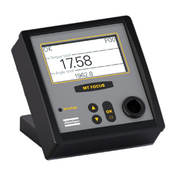
- Seite 11 Operation Start Press and hold the OK button (A) on the controller until the display lights up. The system initializes. All basic functions are checked and displayed during ini- tialization. © Atlas Copco Industrial Technique AB - 9836 629400 00...
- Seite 12 UP or the DOWN buttons to select the number. 5. Set the required tightening torque. Use the UP or the DOWN buttons to set the torque. 6. Press OK. © Atlas Copco Industrial Technique AB - 9836 629400 00...
- Seite 13 1. Press either the UP or the DOWN button 2. Select Batch control in the menu. 3. Press OK. 4. Select Set batch size in the menu. 5. Press OK. © Atlas Copco Industrial Technique AB - 9836 629400 00...
- Seite 14 3. Select Auto-start ON. 4. Press OK. To de-activate Auto-start: 1. Select Auto-start control in the menu. 2. Press OK. 3. Select Auto-start OFF. 4. Press OK. To temporarily disable Auto-start: © Atlas Copco Industrial Technique AB - 9836 629400 00...
- Seite 15 • Cleaning of the tool and controller should be done regularly, but not with aggressive cleanser. • Check wear of the bit regularly. • Replace worn cables immediately. © Atlas Copco Industrial Technique AB - 9836 629400 00...
- Seite 16 Product Instructions MT Focus 400 Tools which have been opened by anyone else than Atlas Copco Industrial Technique AB, will not be serviced. Calibration and preventive maintenance is recommended at regular intervals once per year or after maximum 1.000.000 tightenings depending on which oc- curs sooner.
- Seite 17 • Friction: The internal friction in the tool. • No. tightenings: The total number of tool cycles, including unscrew and Not OK tightenings. • Supply Voltage: The controller supply voltage. 5. Press OK when done. © Atlas Copco Industrial Technique AB - 9836 629400 00...
- Seite 18 Do not open the unit when faced down. 2. With the unit in upright position, open the housing carefully to the left. Do not strain the flat cable from the front. Do not loose the USB isolator. © Atlas Copco Industrial Technique AB - 9836 629400 00...
- Seite 19 Changing the display 1. Open the connector by folding the movable part up and forward, and care- fully pull out the flat cable. 2. Disconnect the white connector by pulling straight up. © Atlas Copco Industrial Technique AB - 9836 629400 00...
- Seite 20 6. Insert the flat cable into the connector. Make sure the cable runs under the small tabs at each side of the con- nector 7. Close the connector by turning the movable part back inte position. © Atlas Copco Industrial Technique AB - 9836 629400 00...
- Seite 21 Please refer to User guide 9836 5312 01: MicroTorque Controller – Software update. Controller upgrade To upgrade the controller from 400B to 400A, contact Support for a new li- cense No. Please refer to User guide 9836 5637 01: ToolsTalk MT. © Atlas Copco Industrial Technique AB - 9836 629400 00...
-
Seite 22: Caractéristiques Techniques
être respectées à tout moment. Ne confiez l'installation et la maintenance qu'à du personnel qualifié. Prendre contact avec le représentant Atlas Copco pour toute question portant sur les consignes de sécurité et les instructions d'utilisation. -
Seite 23: Informations Utiles
• Utiliser des outils insérés ou des consommables de grande qualité pour limi- ter au strict minimum l'exposition à des niveaux excessifs de vibrations. • Limiter l'exposition aux forces de réaction. • Pendant le tronçonnage : © Atlas Copco Industrial Technique AB - 9836 629400 00... - Seite 24 Responsabilité limitée / Garantie Pour toute réclamation concernant un produit, veuillez prendre contact avec votre représentant Atlas Copco. La prise en charge dans le cadre de la garantie n'est acceptée que si le produit a été installé, utilisé et entretenu conformément à...
- Seite 25 100 jours. Connecteurs du contrôleur USB: PC, connecté par câble USB. ALIMENTATION: Connexion de l'alimentation électrique. RS232-C: Interface série, pour divers accessoires. VP: Connexion de la pompe à vide. © Atlas Copco Industrial Technique AB - 9836 629400 00...
- Seite 26 Réglages du port COM : 115200 bauds, 8 bits de données, 1 bit stop, pas de pa- rité, pas de poignée de main. Utiliser un connecteur à broches 3 pôles pour le Binder série 719. Broche Signal Description Données émises © Atlas Copco Industrial Technique AB - 9836 629400 00...
- Seite 27 Masse données Données reçues Sortie pompe à vide (VP) Broche de connexion 5 pôles pour la connexion de la pompe à vide Atlas Copco VPX6 (24 V, 600 mA). Utiliser un connecteur mâle 5 pôles du Binder série 719. Broche...
- Seite 28 Démarrage serrage EXT-IN1 Configurable Réinitialiser l'outil EXT-IN2 Configurable Démarrage desserrage EXT-IN3 Configurable Remise à zéro lot Non utilisée Non utilisée EXT-IN-COM0 Ligne commune externe pour les entrées DGND Masse interne © Atlas Copco Industrial Technique AB - 9836 629400 00...
- Seite 29 EXT-IN0...EXT- IN3 Les entrées sont activées par un signal +24 V appli- qué sur la broche d'entrée. EXT-IN-COM0 Connecter à DGND ou 0 V externe. DGND Sortie 0 V © Atlas Copco Industrial Technique AB - 9836 629400 00...
- Seite 30 3. Fixer le contrôleur sur la surface, de préférence avec les vis retirées. AVIS • Les vis ne doivent pas dépasser dans le contrôleur de plus de 10 mm. © Atlas Copco Industrial Technique AB - 9836 629400 00...
- Seite 31 Flèche BAS : • Entrer dans le menu du système • Faire descendre la sélection Bouton OK : • Mettre le contrôleur en service et hors service • Confirmer la sélection © Atlas Copco Industrial Technique AB - 9836 629400 00...
- Seite 32 MONTÉE ou DESCENTE pour régler le couple de dé- clenchement du comptage d'angle.Appuyer sur OK pour continuer. 14. Pour revoir les réglages, répéter les étapes 10 à 13. 15. Appuyer sur OK pour terminer. © Atlas Copco Industrial Technique AB - 9836 629400 00...
- Seite 33 1. Appuyer sur la touche UP (haut) ou DOWN (bas). 2. Sélectionner Batch control (contrôle des lots) dans le menu. 3. Appuyer sur OK. 4. Sélectionner Decrement batch (décrémenter le lot) dans le menu. © Atlas Copco Industrial Technique AB - 9836 629400 00...
- Seite 34 4. Appuyer sur OK. Pour désactiver temporairement l'auto-démarrage : Placer un objet non magnétique dans l'orifice (A) en façade du coffret, par exemple un crayon. La fonction d'auto-démarrage reprend dès que l'on retire l'objet. © Atlas Copco Industrial Technique AB - 9836 629400 00...
- Seite 35 • Vérifier régulièrement l'usure de l'embout. • Remplacer immédiatement les cordons endommagés. Les outils qui ont été ouverts par quiconque en dehors d'Atlas Copco Industrial Technique AB ne seront pas réparés. Il est recommandé de procéder à l'étalonnage et à la maintenance préventive à...
- Seite 36 (surveillance d'angle d'appui). Seating torque exceeded Le couple d'appui est supérieur à Max. torque (couple maxi.) (visible uniquement si l'option choisie pour Final tightening method (méthode de serrage final) est Torque (couple)). © Atlas Copco Industrial Technique AB - 9836 629400 00...
- Seite 37 • No. tightenings : nombre total de cycles de l'outil, y compris dévis- sages et serrages incorrects. • Supply Voltage : tension d'alimentation du contrôleur. 5. Appuyer sur OK une fois terminé. © Atlas Copco Industrial Technique AB - 9836 629400 00...
- Seite 38 Ne pas ouvrir l'appareil face en bas. 2. Tout en tenant l'appareil en position verticale, ouvrir le boîtier prudemment vers la gauche. Ne pas tirer sur le câble plat. Ne pas perdre l'isolateur USB. © Atlas Copco Industrial Technique AB - 9836 629400 00...
- Seite 39 1. Ouvrir le connecteur en rabattant la pièce mobile vers le haut et vers l'avant et extraire prudemment le câble plat. 2. Débrancher le connecteur blanc en tirant à la verticale. © Atlas Copco Industrial Technique AB - 9836 629400 00...
- Seite 40 6. Insérer le câble plat dans le connecteur. Veiller à faire passer le câble sous les petites languettes de part et d'autre du connecteur. 7. Fermer le connecteur en remettant la partie mobile en place. © Atlas Copco Industrial Technique AB - 9836 629400 00...
- Seite 41 Pour une mise à niveau du contrôleur de 400B à 400A, prendre contact avec le service d'assistance pour obtenir un nouveau numéro de licence. Se reporter au guide d'utilisation 9836 5637 01 : ToolsTalk MT. © Atlas Copco Industrial Technique AB - 9836 629400 00...
-
Seite 42: Sicherheits- Und Bedienungsanweisungen
Alle lokalen gesetzlichen Sicherheitsbestimmungen hinsichtlich Installation, Bedienung und Instandhaltung müssen stets beachtet werden. Installation und Wartung darf nur von erfahrenem Personal ausgeführt werden. Wenden Sie sich an einen Vertreter von Atlas Copco, wenn Sie Fragen bezüg- lich der Sicherheits- und Bedienungsanweisungen haben. Technische Daten Bestell-Nr. -
Seite 43: Nützliche Informationen
0.850 kg Gewicht 1.88 lb Nützliche Informationen Melden Sie sich auf der Website von Atlas Copco an: www.atlascopco.com Auf unserer Website finden Sie Informationen zu unseren Produkten, Zubehör und Ersatzteilen sowie diverse Veröffentlichungen. Ergonomie-Richtlinien Denken Sie an Ihre Arbeitsstation, während Sie diese Liste mit allgemeinen Er- gonomie-Richtlinien lesen und schauen Sie, ob Sie Bereiche identifizieren kön-... - Seite 44 Beziehen Sie sich bitte auf die auf dem Produktetikett angegebenen Informatio- nen. Haftungsausschluss / Garantie Im Gewährleistungsfall nehmen Sie mit Ihrem örtlichen Atlas Copco Handels- vertreter Kontakt auf. Ein Gewährleistungsanspruch kann nur geltend gemacht werden, wenn das Produkt in Übereinstimmung mit der Produktanleitung mon- tiert, betrieben und gewartet wurde.
- Seite 45 Suchfunktionalität für unser gesamtes Lieferprogramm be- reit. ServAid ist auf DVD und auf folgender Webseite erhältlich: http://servaidweb.atlascopco.com Weitere Informationen erhalten Sie bei Ihrem zuständigen Atlas Copco An- sprechpartner, oder schicken Sie eine E-Mail an: servaid.support@se.atlascopco.com Sicherheitsdatenblätter MSDS/SDS Die Sicherheitsdatenblätter stellen Angaben zu von Atlas Copco erhältlichen...
-
Seite 46: Zubehör Anschließen
Anschluss für Armband zum Schutz vor elektrostatischer Entladung HINWEIS Die Drehmoment-Messfunktion der Steuerung reagiert empfindlich auf starke Magnetfelder.Legen Sie keine magnetischen Gegenstände, wie beispielsweise Bohrer, auf die Steuerung oder in deren Nähe ab. Zubehör anschließen © Atlas Copco Industrial Technique AB - 9836 629400 00... - Seite 47 Informationen zur Konfiguration des Eingangs finden Sie unter ToolsTalk MT - Referenz - E/A-Status. Verwenden Sie einen 5-poligen Buchsenstecker der Binder Serie 719. HINWEIS • Dieser Eingang ist nicht opto-isoliert. Eingangswiderstand 10 kΩ © Atlas Copco Industrial Technique AB - 9836 629400 00...
- Seite 48 Beschreibung Vorgegeben INT 24V Interne 24 V Versorgung EXT-AUS-COM0 Externe gemeinsame Lei- tung für Ausgänge EXT-AUS0 Konfigurierbar Aktiv EXT-AUS1 Konfigurierbar Verschraubung i.O. EXT-AUS2 Konfigurierbar Verschraubung n.i.O. EXT-AUS3 Konfigurierbar Gruppe i.O. © Atlas Copco Industrial Technique AB - 9836 629400 00...
- Seite 49 Die Ausgänge werden bei einer Aktivierung an die externe +24 V Versorgung angeschlossen. EXT-EIN0...EXT- EIN3 Die Eingänge werden durch ein am Eingangsstift an- gelegtes +24 V Signal aktiviert. EXT-EIN-COM0 An DGND oder externe 0 V Versorgung anschließen. © Atlas Copco Industrial Technique AB - 9836 629400 00...
- Seite 50 3. Die Steuerung wird vom Kolben fixiert, sobald Sie ihn loslassen. Befestigung mit Schrauben auf der Rückseite 1. Entfernen Sie die beiden Schrauben, mit denen der Steuerungssockel be- festigt ist. © Atlas Copco Industrial Technique AB - 9836 629400 00...
-
Seite 51: Steuergerät
PSatz nicht verwendet werden. In dem Fall muss ein anderer PSatz ausgewählt oder der jeweilige PSatz neu konfiguriert werden. Dies erfolgt über Tools Talk MT oder die AutoSet- Funktion. © Atlas Copco Industrial Technique AB - 9836 629400 00... - Seite 52 UP- oder DOWN-Taste die gewünschte Drehzahl ein. Drücken Sie zum Forfahren auf OK. 11. Muss der Minimalwinkel geändert werden, verwenden SieAUF oder die TasteAB zum Einstellen des Minimalwinkels. Drücken SieOK um fortzu- fahren. © Atlas Copco Industrial Technique AB - 9836 629400 00...
- Seite 53 1. Drücken Sie entweder die Taste UP oder die Taste DOWN 2. Wählen Sie im Menü Batch control. 3. Drücken Sie OK. 4. Wählen Sie im Menü Increment batch. 5. Drücken Sie OK. © Atlas Copco Industrial Technique AB - 9836 629400 00...
- Seite 54 Zeitweilige Deaktivierung von Auto-Start: Stecken Sie einen nicht magnetischen Gegenstand in die Öffnung ( A) vorne an der Steuerung, z.B. einen Bleistift. Die Auto-Start Funktion setzt ein, sobald der Gegenstand entfernt wurde. © Atlas Copco Industrial Technique AB - 9836 629400 00...
-
Seite 55: Wartung
Temperaturbereichs einsetzen. Das Werkzeug, die Steuerung oder die Stromversorgung nicht abdecken. • Werkzeug und Steuerung sind regelmäßig zu reinigen, jedoch mit keinen aggressiven Reinigungsmitteln. • Die Schrauberspitze regelmäßig auf Verschleiß kontrollieren. © Atlas Copco Industrial Technique AB - 9836 629400 00... - Seite 56 Produktanweisungen MT Focus 400 • Verschlissene Kabel unverzüglich austauschen. Werkzeuge, die von jemand anderem als Atlas Copco Industrial Technique AB geöffnet wurden, werden nicht gewartet. Es wird empfohlen, regelmäßig – zumindest ein Mal jährlich oder alle 1 Mio. Verschraubungen (je nachdem, was früher eintritt) – eine Kalibrierung und vor- beugende Wartung durchzuführen.
- Seite 57 Drehmoment. Unscrew Ausschraubvorgang aktiv. Steuerungssysteminformationen Informationsanzeige: 1. Drücken Sie entweder die Taste AUF oder die Taste AB. 2. Wählen Sie System information (Systeminformationen) im Menü aus. 3. Drücken Sie OK. © Atlas Copco Industrial Technique AB - 9836 629400 00...
- Seite 58 • Reibung: Die innere Reibung im Werkzeug. • Anz. Verschraubungen: Die Gesamtzahl der Werkzeugzyklen, ein- schließlich Ausschraubvorgänge und NIO-Verschraubungen. • Versorgungsspannung: Die Versorgungsspannung der Steuerung. 5. Drücken Sie danach OK. © Atlas Copco Industrial Technique AB - 9836 629400 00...
- Seite 59 Das Gerät nicht mit der Vorderseite nach unten öffnen. 2. Das Gerät in aufrechter Position halten und das Gehäuse vorsichtig nach links öffnen. Das Flachkabel nicht zu sehr anspannen. Den USB-Trenner nicht lösen. © Atlas Copco Industrial Technique AB - 9836 629400 00...
- Seite 60 Sicherstellen, dass der Hohllichtleiter korrekt positioniert ist. 6. Die Werkzeugaufnahme montieren. 7. Das Flachkabel in die Steckverbindung einsetzen und die Steckverbindung schließen. Hierzu das bewegliche Teil mit einem kleinen Schraubendreher eindrücken. © Atlas Copco Industrial Technique AB - 9836 629400 00...
- Seite 61 6. Das Flachkabel in die Steckverbindung einsetzen. Sicherstellen, dass das Kabel unter den kleinen auf beiden Seiten der Steckverbindung befindlichen Laschen geführt wird. 7. Die Steckverbindung schließen. Hierzu das bewegliche Teil zurück in Po- sition bringen. © Atlas Copco Industrial Technique AB - 9836 629400 00...
- Seite 62 1. Das Gehäuse schließen. HINWEIS • Sicherstellen, dass sich Display und USB-Trenner in ihrer korrek- ten Position befinden. • Sicherstellen, dass das Flachkabel nicht beschädigt wird. 2. Die vier Schrauben montieren. © Atlas Copco Industrial Technique AB - 9836 629400 00...
- Seite 63 Wenn Sie ein Upgrade von 400B auf 400A vornehmen möchten, setzen Sie sich für eine neue Lizenznummer mit dem Kundensupport in Verbindung. Beziehen Sie sich bitte auf das Benutzerhandbuch 9836 5637 01: ToolsTalk MT. © Atlas Copco Industrial Technique AB - 9836 629400 00...
-
Seite 64: Es Instrucciones Del Producto
La instalación y el servicio deberá efectuarlo únicamente personal cualificado. Contacte con su representante de Atlas Copco si tiene alguna duda sobre las instrucciones de seguridad y funcionamiento. -
Seite 65: Información Útil
• Utilice herramientas o consumibles insertados de alta calidad para minimi- zar la exposición a excesivos niveles de vibración. • Minimice la exposición a fuerzas de reacción. • Durante el corte: © Atlas Copco Industrial Technique AB - 9836 629400 00... - Seite 66 Consulte la información en la etiqueta del producto. Garantía / responsabilidad limitada Póngase en contacto con el representante de ventas de Atlas Copco de su área para realizar cualquier tipo de reclamación. La garantía solo será válida si el producto se ha instalado, se ha utilizado y se le ha realizado el mantenimiento del modo que establecen las instrucciones del producto.
- Seite 67 100 días sin necesidad de recarga. Conectores del controlador USB: PC, conectado a través de un cable USB. POWER: conexión para el suministro de corriente. RS232-C: interfaz en serie, para varios accesorios © Atlas Copco Industrial Technique AB - 9836 629400 00...
-
Seite 68: Conexión De Accesorios
Parámetros del puerto COM: 115200 baudios, 8 bits de datos, 1 bit de parada, sin paridad, sin protocolo de enlace. Utilice un enchufe de 3 patillas de la serie Binder 719. © Atlas Copco Industrial Technique AB - 9836 629400 00... - Seite 69 • Si se utiliza para restablecer la herramienta, la duración de la señal debe ser superior a 40 ms. Patilla Salida Descripción Predet. +24 V Interna +24 V GND (0 V) Salida 0 V Entrada digital Entrada digital Iniciar apriete © Atlas Copco Industrial Technique AB - 9836 629400 00...
- Seite 70 Apriete incorrecto EXT-OUT3 Configurable Lote correcto No utilizado EXT-IN0 Configurable Iniciar apriete EXT-IN1 Configurable Reset tool (Herramienta de reinicio) EXT-IN2 Configurable Iniciar desapriete EXT-IN3 Configurable Reiniciar lote No utilizado No utilizado © Atlas Copco Industrial Technique AB - 9836 629400 00...
- Seite 71 EXT-IN0...EXT- IN3 Las entradas serán activadas por una señal de +24 V aplicada a la patilla de entrada. EXT-IN-COM0 Conectar a DGND o 0 V externa. DGND Salida 0 V © Atlas Copco Industrial Technique AB - 9836 629400 00...
- Seite 72 3. Instale el controlador en la superficie, preferiblemente sin los tornillos. AVISO • Los tornillos no deben entrar más de 10 mm en el controlador. © Atlas Copco Industrial Technique AB - 9836 629400 00...
- Seite 73 • Desplazar la selección hacia arriba Botón DOWN : • Elegir el menú del sistema • Desplazar la selección hacia abajo Botón OK : • Encender y apagar el controlador • Confirmar la selección © Atlas Copco Industrial Technique AB - 9836 629400 00...
- Seite 74 13. Si tiene que modificar el par del gatillo para el contador de ángulo, utilice los botonesUP oDOWN para establecer el par del gatillo para el contador de ángulo.PulseOK para continuar. 14. Para revisar los ajustes, repita los pasos 10-13. 15. PulseOK para finalizar. © Atlas Copco Industrial Technique AB - 9836 629400 00...
- Seite 75 Para disminuir el número de lote: 1. Pulse los botones ARRIBA o ABAJO 2. Seleccione Control de lotes en el menú. 3. Haga clic en Aceptar. 4. Seleccione Disminuir lote en el menú. © Atlas Copco Industrial Technique AB - 9836 629400 00...
- Seite 76 Coloque un objeto no magnético en el orificio (A) en la parte delantera del con- trolador, por ejemplo un lapicero. La función Auto-start se reanudará cuando se retire el objeto. © Atlas Copco Industrial Technique AB - 9836 629400 00...
- Seite 77 1.000.000 de tensiones como máximo, lo que ocurra en primer lugar. Es posible que sea necesario un mayor número de revisiones si hace un uso in- tensivo de la máquina. © Atlas Copco Industrial Technique AB - 9836 629400 00...
- Seite 78 última calibración. Se ha excedido el Max. time definido para la etapa Time exceeded Time not reached No se ha alcanzado el Min. time definido para la eta- © Atlas Copco Industrial Technique AB - 9836 629400 00...
- Seite 79 • Nº. de aprietes: El número total de ciclos de la herramienta, incluyen- do los desenroscados y los aprietes incorrectos. • Tensión de alimentación: la tensión de suministro del controlador. 5. Pulse OK al terminar. © Atlas Copco Industrial Technique AB - 9836 629400 00...
- Seite 80 No abra la unidad cuando esté boca abajo. 2. Con la unidad en posición vertical, abra cuidadosamente la carcasa hacia la izquierda. No tense el cable plano de la parte delantera. No pierda el aislante del USB. © Atlas Copco Industrial Technique AB - 9836 629400 00...
- Seite 81 Para cambiar la pantalla 1. Abra el conector plegando la parte móvil hacia arriba y hacia delante y tire cuidadosamente del cable plano. 2. Desconecte el conector blanco tirando recto hacia arriba. © Atlas Copco Industrial Technique AB - 9836 629400 00...
- Seite 82 Asegúrese de que el cable se encuentra por debajo de las pequeñas len- güetas situadas a ambos lados del conector. 7. Cierre el conector colocando la pieza móvil en su posición. © Atlas Copco Industrial Technique AB - 9836 629400 00...
- Seite 83 Para actualizar el controlador del 400B al 400A, póngase en contacto con el Servicio de asistencia para obtener un nuevo número de licencia. Consulte la Guía del usuario 9836 5637 01: ToolsTalk MT. © Atlas Copco Industrial Technique AB - 9836 629400 00...
-
Seite 84: Pt Instruções Para Produto
Todas as normas de segurança conforme legislação local, com relação à instalação, operação e manutenção precisam ser sempre respeitadas. Confie a instalação e a assistência apenas a pessoal competente. Entre em contato com o seu representante Atlas Copco caso surjam dúvidas sobre as instruções de segurança e operação. Dados técnicos Nº... - Seite 85 O disco de corte poderá enroscar se estiver empenado ou não for guiado adequadamente. Verifique se está usando flanges corretos para os discos de corte e evite entortar o disco durante a operação de corte. © Atlas Copco Industrial Technique AB - 9836 629400 00...
- Seite 86 Consulte as informações na etiqueta do produto. Garantia/Responsabilidade Limitada Entre em contato com o representante de vendas da Atlas Copco na sua região para reivindicar a garantia de um produto. A garantia só será aprovada se o produto tiver sido instalado, operado e revisado de acordo com as instruções do produto.
- Seite 87 VP: Conexão da bomba de aspiração. Ferramenta, conectada com o cabo. I/O: Entrada digital única com um propósito específico. DIGITAL I/O: Conexão para diversos acessórios. Conexão para a pulseira de proteção ESD © Atlas Copco Industrial Technique AB - 9836 629400 00...
- Seite 88 Definições da porta COM: Transmissão de dados de 115200, 8 bits de dados, 1 bit de parada, sem paridade, sem handshake. Use um conector macho de 3 pinos da Série Binder 719. Pino Sinal Descrição Dados transmitidos Dados do aterramento Dados recebidos © Atlas Copco Industrial Technique AB - 9836 629400 00...
- Seite 89 MT Focus 400 Instruções para Produto Saída de bomba de aspiração (VP) Conector de 5 pinos para conexão com a bomba de Aspiração Atlas Copco VPX6 (24 V, 600 mA). Use um conector macho de 5 pinos da Série Binder 719.
- Seite 90 Configurável Iniciar aperto EXT-IN1 Configurável Reinicializar a ferramenta EXT-IN2 Configurável Iniciar desaperto EXT-IN3 Configurável Reinicializar o lote Não usado Não usado EXT-IN-COM0 Linha comum externa para entradas DGND Aterramento interno © Atlas Copco Industrial Technique AB - 9836 629400 00...
- Seite 91 EXT-IN0...EXT- IN3 As entradas serão ativadas com um sinal +24 V aplicado ao pino de entrada. EXT-IN-COM0 Conecte à DGND ou à 0 V externa. DGND Saída de 0 V © Atlas Copco Industrial Technique AB - 9836 629400 00...
- Seite 92 2. Faça dois furos de 5 mm na superfície, correspondendo aos furos na parte traseira do controlador. Deixe espaço sobre os furos para os conectores e a abertura de som. © Atlas Copco Industrial Technique AB - 9836 629400 00...
- Seite 93 Botão PARA CIMA: • Insira o menu do sistema • Mova a seleção para cima Botão PARA BAIXO: • Insira o menu do sistema • Mova a seleção para baixo © Atlas Copco Industrial Technique AB - 9836 629400 00...
- Seite 94 13. If the trigger torque for angle counting is to be changed, use the UP or the DOWN buttons to set the trigger torque for angle counting. Press OK to continue. 14. Para revisar os ajustes, as etapas 10-13. 15. Press OK to finish. © Atlas Copco Industrial Technique AB - 9836 629400 00...
- Seite 95 1. Pressione o botão PARA CIMA ou PARA BAIXO 2. Selecione Controle de lote no menu. 3. Pressione OK. 4. Selecione Reduzir lote no menu. 5. Pressione OK. Para reinicializar o número do lote: © Atlas Copco Industrial Technique AB - 9836 629400 00...
- Seite 96 To temporarily disable Auto-start: Put a non-magnetic object in the hole (A) on the front of the controller, for example a pencil. A função Início automático será reiniciada quando o objeto for removido. © Atlas Copco Industrial Technique AB - 9836 629400 00...
-
Seite 97: Manutenção
• Verifique regularmente o desgaste da ponta da ferramenta. • Substitua cabos desgastados imediatamente. As ferramentas abertas por alguém que não seja da Atlas Copco Industrial Technique AB não serão incluídas na assistência. Recomenda-se efetuar a calibração e a manutenção preventiva em intervalos regulares, uma vez por ano ou no máximo depois de 1.000.000 apertos,... - Seite 98 O torque Mín. definido para a etapa não foi atingido. Torque não atingido Total torque too low Total step torque is lower than Min. allowed torque. Desparafusar Processo de desparafusamento ativo. © Atlas Copco Industrial Technique AB - 9836 629400 00...
- Seite 99 • Friction: Atrito interno na ferramenta. • No. tightenings: Total de ciclos da ferramenta, incluindo desparafusar e apertos NOK. • Supply Voltage: A tensão de entrada do controlador. 5. Pressione OK quando terminar. © Atlas Copco Industrial Technique AB - 9836 629400 00...
- Seite 100 Não abra a unidade quando ela estiver virada para baixo. 2. Com a unidade em pé, abra a carcaça cuidadosamente para a esquerda. Não estique o cabo flat da frente. Não remova o isolador USB. © Atlas Copco Industrial Technique AB - 9836 629400 00...
- Seite 101 Troca da tela 1. Abra o conector dobrando a peça móvel para cima e para frente, em seguida puxe o cabo flat cuidadosamente. 2. Remova o conector branco puxando-o para cima. © Atlas Copco Industrial Technique AB - 9836 629400 00...
- Seite 102 Certifique-se de que o cabo passe por baixo das pequenas aletas em cada lado do conector 7. Feche o conector pondo a peça móvel de volta na sua posição original. © Atlas Copco Industrial Technique AB - 9836 629400 00...
- Seite 103 Para fazer o upgrade do controlador do 400B para o 400A, entre em contato com o Suporte para obter um novo nº de licença. Consulte o Guia do usuário 9836 5637 01: ToolsTalk MT. © Atlas Copco Industrial Technique AB - 9836 629400 00...
-
Seite 104: It Istruzioni Sul Prodotto
Rivolgersi esclusivamente a personale addestrato per le operazioni di installa- zione ed assistenza. Contattare il rappresentante Atlas Copco in caso di dubbi relativi alle istruzioni di sicurezza e per l'uso. Dati tecnici N. -
Seite 105: Informazioni Utili
• Utilizzare utensili o materiali di consumo di elevata qualità per ridurre al minimo l'esposizione a livelli eccessivi di vibrazioni. • Minimizzare l'esposizione a forze di reazione. • Durante il taglio: © Atlas Copco Industrial Technique AB - 9836 629400 00... - Seite 106 Fare riferimento alle informazioni sull'etichetta del prodotto. Responsabilità limitata / Garanzia Contattare il rappresentante Atlas Copco della propria zona per presentare re- clami in merito a un prodotto. La garanzia verrà approvata solo se il prodotto è stato installato, utilizzato e sottoposto a manutenzione secondo le istruzioni re- lative al prodotto.
-
Seite 107: Schede Informative In Materia Di Sicurezza Msds/Sds
ServAid offre una funzionalità di ricerca avanzata per l'intera gamma di prodotti Atlas Copco. ServAid è disponibile in DVD e sul Web: http://servaidweb.atlascopco.com Per ulteriori informazioni, contattare il proprio rappresentante Atlas Copco op- pure scrivere una mail a: servaid.support@se.atlascopco.com Schede informative in materia di sicurezza MSDS/SDS Le schede informative in materia di sicurezza descrivono i prodotti chimici commercializzati da Atlas Copco. - Seite 108 Impostazioni porta COM: 115200 Baud, 8 bit di dati, 1 bit di stop, nessuna pari- tà, nessuna sincronizzazione. Utilizzare una spina maschio a 3 poli della serie Binder 719. Segnale Descrizione Dati trasmessi © Atlas Copco Industrial Technique AB - 9836 629400 00...
- Seite 109 Terra Terra dati Dati ricevuti Uscita della pompa del vuoto (VP) Connettore a 5 poli per il collegamento della pompa del vuoto Atlas Copco VPX6 (24V, 600 mA). Utilizzare una spina maschio a 5 poli della serie Binder 719. Uscita...
- Seite 110 Avvia serraggio EXT-IN1 Configurabile Reset tool (Reset utensile) EXT-IN2 Configurabile Avvia svitatura EXT-IN3 Configurabile Resetta lotto Non utilizzato Non utilizzato EXT-IN-COM0 Linea comune esterna per gli ingressi DGND Massa interna © Atlas Copco Industrial Technique AB - 9836 629400 00...
- Seite 111 Gli ingressi saranno attivati da un segnale a +24 V ap- plicato al pin di ingresso. EXT-IN-COM0 Collega a DGND o esterna 0 V. DGND Uscita 0 V modalità NPN © Atlas Copco Industrial Technique AB - 9836 629400 00...
- Seite 112 3. Fissare il controller alla superficie, preferibilmente con le viti rimosse. NOTA • Le viti non devono sporgere nel controller di oltre 10 mm. Funzionamento Start (Avvio) © Atlas Copco Industrial Technique AB - 9836 629400 00...
- Seite 113 • Conferma la selezione Indicatore di STATO: • Verde - Serraggio OK • Blu - Lotto completato • Rosso - Errore Impostazione automatica 1. Premere il pulsante SU o il pulsante GIÙ © Atlas Copco Industrial Technique AB - 9836 629400 00...
- Seite 114 4. Se richiesto, inserire la password. Utilizzare il pulsante OK per selezionare una posizione e i pulsanti SU oppure GIÙ per selezionare il numero. 5. Selezionare l'impostazione di programma richiesta. © Atlas Copco Industrial Technique AB - 9836 629400 00...
- Seite 115 4. Selezionare Resetta lotto nel menu. 5. Premere OK. Funzione Auto-start Se la funzione "Auto-Start" (Avvio automatico) è stata abilitata da ToolsTalk, verrà visualizzato il menu aggiuntivo associato a tale funzione. © Atlas Copco Industrial Technique AB - 9836 629400 00...
- Seite 116 © Atlas Copco Industrial Technique AB - 9836 629400 00...
- Seite 117 • Controllare regolarmente l'usura della punta. • Sostituire immediatamente i cavi usurati. Gli utensili aperti da persone terze non autorizzate da Atlas Copco Industrial Technique AB non verranno riparati. È consigliabile eseguire la taratura e la manutenzione preventiva ad intervalli regolari, una volta all'anno, oppure dopo 1.000.000 di serraggi, a seconda di...
- Seite 118 Il Min. time definito per il passaggio non è stato rag- giunto. Il Max. torque definito per il passaggio è stato supe- Torque exceeded rato. Torque not reached Il Min. torque definito per il passaggio non è stato raggiunto. © Atlas Copco Industrial Technique AB - 9836 629400 00...
- Seite 119 • No. tightenings (N. serraggi): Indica il numero totale di cicli eseguiti dall'utensile, inclusi svitamenti e serraggi falliti. • Supply Voltage (Tensione di alimentazione): la tensione di alimenta- zione del controller. 5. Premere OK al completamento. © Atlas Copco Industrial Technique AB - 9836 629400 00...
-
Seite 120: Prevenzione Dei Problemi Dovuti Alle Scariche Elettrostatiche
Non aprire l'unità rivolta verso il basso. 2. Con l'unità in posizione verticale, aprire attentamente l'alloggiamento verso sinistra. Non sottoporre a sforzi il cavo piatto dalla parte anteriore. Non allentare l'isolatore USB. © Atlas Copco Industrial Technique AB - 9836 629400 00... - Seite 121 Sostituzione del display 1. Aprire il connettore piegando verso l'alto e in avanti la parte mobile ed estrarre attentamente il cavo piatto. 2. Scollegare il connettore bianco tirandolo verso l'alto. © Atlas Copco Industrial Technique AB - 9836 629400 00...
- Seite 122 6. Inserire il cavo piatto nel connettore. Assicurarsi che il cavo scorra sotto le linguette su ciascun lato del con- nettore. 7. Chiudere il connettore riportando in posizione la parte mobile. © Atlas Copco Industrial Technique AB - 9836 629400 00...
- Seite 123 Per eseguire l'upgrade del controller da 400B a 400A, contattare il Centro di supporto per un nuovo numero di licenza. Fare riferimento alla Guida utente 9836 5637 01: ToolsTalk MT. © Atlas Copco Industrial Technique AB - 9836 629400 00...
- Seite 124 Alla lokala lagstiftade säkerhetsregler vad gäller installation, drift och underhåll måste följas vid alla tillfällen. Installation och service får endast utföras av behörig personal. Kontakta din Atlas Copco-representant om det uppstår frågor när det gäller säkerhets- och användarinstruktioner. Tekniska data Beställningsnummer...
-
Seite 125: Användbar Information
• Använd hörselskydd där det förekommer buller. • Använd högkvalitativa insatta verktyg eller förbrukningsartiklar för att minimera exponeringen av höga nivåer av vibrationer. • Minimera exponeringen för reaktionskrafter. • Vid kapning: © Atlas Copco Industrial Technique AB - 9836 629400 00... - Seite 126 ServAid kan användas för att vissa innehåll på ett visst språk, om det finns översättningar, och för att visa information om utgångna produkter. I ServAid finns en avancerad sökfunktion med hela vårt produktsortiment. ServAid finns på DVD och på internet: http://servaidweb.atlascopco.com © Atlas Copco Industrial Technique AB - 9836 629400 00...
- Seite 127 MT Focus 400 Produktinstruktioner För ytterligare information kontakta din återförsäljare för Atlas Copco eller skicka e-post på adressen: servaid.support@se.atlascopco.com Säkerhetsdatablad MSDS/SDS Säkerhetsdatabladen beskriver kemiska produkter som säljs av Atlas Copco. För mer information, gå till webbplatsen http://www.atlascopco.com/. Välj Produkter – Säkerhetsdatablad, och följ instruktionerna på sidan.
- Seite 128 3-poligt hylstag för seriellt gränssnitt. COM-portinställningar: 115200 baud, 8 databits, 1 stoppbit, ingen paritet, ingen handskakning. Använd en 3-polig stiftpropp från serien Binder 719. Stift Signal Beskrivning Överförd data Datajord Mottagen data © Atlas Copco Industrial Technique AB - 9836 629400 00...
- Seite 129 MT Focus 400 Produktinstruktioner Vakuumpump (VP) 5-polig kontakt för anslutning av Atlas Copco vakuumpump VPX6 (24 V, 600 mA). Använd en 5-polers stiftkontakt från Binder 719-serien. Stift Utgång Beskrivning Standard +24 V Intern +24 V +24 V Intern +24 V Pump på...
- Seite 130 Återställ grupp Ej använd Ej använd EXT-IN-COM0 Extern gemensam ledning för ingångar DGND Intern jord För information om konfiguration av ingångarna och utgångarna, se ToolsTalk MT - Referens - I/O-status. © Atlas Copco Industrial Technique AB - 9836 629400 00...
- Seite 131 Utgångarna ansluts till den externa +24 V om de är aktiverade. EXT-IN0...EXT- IN3 Ingångarna aktiveras av en +24 V signal som läggs på ingångsstiftet. EXT-IN-COM0 Anslut till DGND eller extern 0 V. DGND 0 V utgång NPN-läge © Atlas Copco Industrial Technique AB - 9836 629400 00...
- Seite 132 3. Fäst styrenheten på ytan, helst med de lossade skruvarna. OBSERVERA • Skruvarna får inte sticka ut mer än 10 mm. Användning Start Tryck och håll in OK -knappen (A) på styrenheten tills displayen tänds. © Atlas Copco Industrial Technique AB - 9836 629400 00...
- Seite 133 2. Välj Auto-set i menyn. 3. Tryck på OK. 4. Ange lösenord om så krävs. Använd knappen OK för att välja nästa siffra respektive UP eller DOWN för att ändra värdet. © Atlas Copco Industrial Technique AB - 9836 629400 00...
- Seite 134 UP eller DOWN för att ändra värdet. 5. Välj önskad programinställning. 6. Tryck på OK. Satsövervakning För att ställa in satsstorlek: 1. Tryck antingen på knappen UP eller DOWN 2. Välj Batch control i menyn. © Atlas Copco Industrial Technique AB - 9836 629400 00...
- Seite 135 1. Välj Auto-start control i menyn. 2. Tryck på OK. 3. Välj Auto-start ON. 4. Tryck på OK. För att inaktivera Auto-start: 1. Välj Auto-start control i menyn. 2. Tryck på OK. © Atlas Copco Industrial Technique AB - 9836 629400 00...
-
Seite 136: Underhåll
• Utsätt aldrig systemet för stora vibrationer eller stor luftfuktighet. • Förhindra överhettning genom att endast använda det inom det tillåtna temperaturintervallet. Täck inte över verktyget eller driv-/styrenheten eller spänningsmatningen. © Atlas Copco Industrial Technique AB - 9836 629400 00... - Seite 137 • Kontrollera bitsens slitage regelbundet. • Byt slitna kablar omedelbart. För verktyg som öppnats av någon annan än Atlas Copco Industrial Technique AB, kommer service inte att utföras. Vi rekommenderar kalibrering och förebyggande underhåll med regelbundna intervall en gång per år eller efter högst 1 000 000 åtdragningar beroende på...
- Seite 138 • Verktyg S/W: Verktygets programvaruversion. • Friktion: Verktygets inre friktion. • Ant. åtdragningar: Verktygets totala antal cykler, inklusive lossning och NOK-åtdragningar. • Matningsspänning: Styrenhetens matningsspänning. 5. Tryck OK när du är klar. © Atlas Copco Industrial Technique AB - 9836 629400 00...
- Seite 139 Öppna inte enheten om den är vänd nedåt. 2. När enheten står upprätt, öppna höljet försiktigt åt vänster. Var försiktig så att flatkabeln inte lossar från höljet. Lossa inte USB-isolatorn. © Atlas Copco Industrial Technique AB - 9836 629400 00...
- Seite 140 Byta display 1. Öppna kontakten genom att vika den rörliga delen uppåt och framåt och drag försiktigt ut flatkabeln. 2. Lossa den vita kontakten genom att dra rakt uppåt. © Atlas Copco Industrial Technique AB - 9836 629400 00...
- Seite 141 6. Sätt i flatkabeln i kontakten. Kontrollera att kabeln löper under de små flikarna på kontaktens båda sidor. 7. Stäng kontakten genom att vrida tillbaka den rörliga delen till ursprungsläget. © Atlas Copco Industrial Technique AB - 9836 629400 00...
- Seite 142 Se Användarguiden 9836 5312 01: MicroTorque-styrenhet – Programuppdatering. Uppgradering av styrenheten För att uppgradera styrenheten från 400B till 400A, kontakta Supportavdelningen för ett nytt licensnummer. Se Användarguiden 9836 5637 01: ToolsTalk MT. © Atlas Copco Industrial Technique AB - 9836 629400 00...
-
Seite 143: Dane Techniczne
Instalację i serwisowanie należy zawsze powierzać wyłącznie wykwalifikowa- nemu personelowi. W przypadku jakichkolwiek pytań dotyczących instrukcji bezpieczeństwa i ob- sługi prosimy o kontakt z lokalnym przedstawicielem firmy Atlas Copco. Dane techniczne Nr zamówieniowy 8432085000... -
Seite 144: Przydatne Informacje
• Stosuj oświetlenie odpowiednie do wykonywanego zadania. • Wybieraj narzędzie odpowiednie do wykonywanego zadania. • W środowisku o wysokim natężeniu hałasu stosuj środki ochrony słuchu. © Atlas Copco Industrial Technique AB - 9836 629400 00... - Seite 145 Nie wolno otwierać obudowy zespołu napędowego, obudowy sterownika i obu- dowy zasilacza. Zerwanie plomb skutkuje unieważnieniem gwarancji. ServAid ServAid jest aplikacją przeznaczoną do uzyskiwania zaktualizowanych infor- macji o produkcie, dotyczących: - instrukcji bezpieczeństwa © Atlas Copco Industrial Technique AB - 9836 629400 00...
-
Seite 146: Podstawowa Konfiguracja
Niektóre funkcje sterownika, takie jak wbudowany zegar, są zasilane z we- wnętrznego akumulatora. Czas ładowania wynosi 5 godzin, zaś akumulator mo- że funkcjonować przez 100 dni przed ponownym ładowaniem. © Atlas Copco Industrial Technique AB - 9836 629400 00... -
Seite 147: Podłączanie Akcesoriów
Złącze do podłączania antystatycznej opaski na nadgarstek. UWAGA Zawarta w sterowniku funkcja pomiaru momentu dokręcania jest wrażliwa na silne pola magnetyczne.Nie umieszczać namagnesowanych przedmiotów, na przykład końcówek wkrętakowych, na lub w pobliżu sterownika. Podłączanie akcesoriów © Atlas Copco Industrial Technique AB - 9836 629400 00... - Seite 148 W celu uzyskania informacji na temat konfiguracji wejścia, patrz ToolsTalk MT — Objaśnienia — Stan wejścia/wyjścia. Stosować 5-biegunowy wtyk gniazdowy z serii Binder 719. UWAGA • To wejście nie jest odizolowane optycznie. © Atlas Copco Industrial Technique AB - 9836 629400 00...
- Seite 149 • W przypadku przekroczenia maksymalnej wartości natężenia prądu na- pięcie wyjściowe zostanie wyłączone. Problem ten można rozwiązać, wyłączając i ponownie włączając wyjście. Styk Opis Domyślnie INT 24V Wewnętrzne zasilanie 24 EXT-OUT-COM0 Zewnętrzna linia wspólna dla wyjść © Atlas Copco Industrial Technique AB - 9836 629400 00...
- Seite 150 Tryb NPN (tryb wyjściowy, logika ujemna). Tryb PNP Opis INT -24V Wyjście +24 V EXT-OUT-COM0 Podłączyć do INT +24 V lub zewnętrznego napięcia +24 V (nie równocześnie) © Atlas Copco Industrial Technique AB - 9836 629400 00...
- Seite 151 • Zamocowanie do pionowej powierzchni przy użyciu wspornika ściennego. • Zamocowanie do pionowej powierzchni przy użyciu umieszczonych z tyłu wkrętów. Zamocowanie przy użyciu wspornika ściennego 1. Zamocować wspornik do powierzchni przy użyciu czterech wkrętów 5 mm. © Atlas Copco Industrial Technique AB - 9836 629400 00...
- Seite 152 Następuje inicjalizacja systemu.Podczas inicjalizacji zostają sprawdzone i wy- świetlone wszystkie podstawowe funkcje. OSTRZEŻENIE • Wrzeciono obraca się, gdy system jest włączony i przeprowadzana jest kali- bracja narzędzia. Po pomyślnym zakończeniu inicjalizacji system jest gotowy do użytku. © Atlas Copco Industrial Technique AB - 9836 629400 00...
- Seite 153 UP (W GÓRĘ) lub DOWN (W DÓŁ). 6. Nacisnąć przycisk OK. 7. Sprawdzić, czy pokazywane jest właściwe ustawienie PSet.Jeśli tak, wy- brać opcjęyes (tak) i nacisnąćOK. Jeśli nie, powrócić przez wybranie opcjino (nie) i naciśnięcieOK. © Atlas Copco Industrial Technique AB - 9836 629400 00...
- Seite 154 6. Nacisnąć przycisk OK. Regulacja partii Aby ustawić wielkość partii, należy: 1. Nacisnąć przycisk UP (W GÓRĘ) lub DOWN (W DÓŁ). 2. Wybrać w menu opcję Batch control (Regulacja partii). © Atlas Copco Industrial Technique AB - 9836 629400 00...
- Seite 155 Włączanie automatycznego uruchamiania: 1. Wybrać opcjęAuto-start control (Sterowanie automatycznym urucha- mianiem) w menu. 2. Nacisnąć przycisk OK. 3. Wybrać opcjęAuto-start ON (Automatyczne uruchamianie włączone). 4. Nacisnąć przycisk OK. Wyłączanie automatycznego uruchamiania: © Atlas Copco Industrial Technique AB - 9836 629400 00...
-
Seite 156: Konserwacja
Istnieją pewne ogólne procedury konserwacyjne, które należy wykonywać w celu utrzymywania systemu MicroTorque w czystości oraz w celu zapewnie- nia jego pracy z pełną wydajnością. System jest skomplikowanym narzędziem, składającym się z wielu wrażliwych elementów. © Atlas Copco Industrial Technique AB - 9836 629400 00... - Seite 157 Końcówka wyślizguje się z połączenia, gdy moment dokręcania osiągnie 70% wartości docelowej [jeśli dla funkcji Bit slip detection (Wykrywanie wyśli- zgiwania się końcówki) ustawiona jest opcja On (Wł.)]. Cancel Dokręcanie zostało anulowane. System jest wyłączony. Disable © Atlas Copco Industrial Technique AB - 9836 629400 00...
- Seite 158 Ustalona wartość Min. torque dla danego kroku nie Torque not reached została osiągnięta. Total torque too low Całkowity etapowy moment dokręcania jest mniejszy niżMin. allowed torque (Min. dopuszczalny mo- ment dokręcania). Unscrew Aktywny proces odkręcania. © Atlas Copco Industrial Technique AB - 9836 629400 00...
- Seite 159 • Friction: Wewnętrzne tarcie w narzędziu. • No. tightenings: Łączna liczba cykli pracy narzędzia, z uwzględnie- niem odkręcania i nieprawidłowych dokręceń. • Supply Voltage: Napięcie zasilania sterownika. 5. Nacisnąć przycisk OK po zakończeniu przeglądania informacji. © Atlas Copco Industrial Technique AB - 9836 629400 00...
- Seite 160 Nie otwierać urządzenia skierowanego przednim panelem do dołu. 2. Trzymając urządzenie pionowo, ostrożnie otworzyć obudowę w lewo. Nie naciągać płaskiego kabla zamocowanego do przedniego panelu. Uważać, aby nie zgubić izolatora gniazda USB. © Atlas Copco Industrial Technique AB - 9836 629400 00...
- Seite 161 7. Włożyć płaski kabel w złącze, po czym zamknąć złącze, naciskając rucho- mą część małym śrubokrętem. Wymiana wyświetlacza 1. Otworzyć złącze, odginając ruchomą część do góry i do przodu, po czym ostrożnie wyciągnąć płaski kabel. © Atlas Copco Industrial Technique AB - 9836 629400 00...
- Seite 162 6. Włożyć płaski kabel w złącze. Upewnić się, że kabel umieszczony jest pod małymi występami z bo- ków złącza. 7. Zamknąć złącze, obracając jego ruchomą część z powrotem na właściwe miejsce. © Atlas Copco Industrial Technique AB - 9836 629400 00...
- Seite 163 Aby wymienić sterownik z wersji 400B na wersję 400A, należy skontaktować się z działem wsparcia technicznego w celu uzyskania nowego numeru licencji. Więcej informacji można znaleźć w instrukcji użytkownika nr 9836 5637 01: ToolsTalk MT. © Atlas Copco Industrial Technique AB - 9836 629400 00...
-
Seite 164: Cs Pokyny K Používání Výrobku
- dB(A) Akustický standard Akustická nestálost - dB(A) Rozsah otáček - ot./min Rozsah utahovacího momentu 0.5–250 cNm Rozsah utahovacího momentu -– in lb Napětí - V Napájení 240 W Napětí motoru - V Výkon motoru - W Standardní vibrace © Atlas Copco Industrial Technique AB - 9836 629400 00... -
Seite 165: Užitečné Informace
Pokud je řezný kotouč ohnutý nebo pokud není správně veden, může dojít k jeho zaseknutí. Ujistěte se, že pro řezné kotouče používáte správné přírubové spojky, a při řezání se vyhněte ohýbání kotouče. © Atlas Copco Industrial Technique AB - 9836 629400 00... - Seite 166 Omezená odpovědnost / záruka Chcete-li výrobek reklamovat, kontaktujte prodejního zástupce společnosti Atlas Copco ve vaší oblasti. Záruka bude schválena pouze v případě, že výrobek byl nainstalován, provozován a byla na něm prováděna údržba podle pokynů týkajících se produktu. Záruční plnění nebude schváleno, bude-li zjištěno, že byl nástroj otevřen.
-
Seite 167: Instalace
Doba nabíjení baterie je 5 hodin a bez dobíjení dokáže zajistit napájení po dobu 100 dní. Konektory řídicí jednotky USB: PC, připojen pomocí kabelu USB. POWER: Připojení napájení. RS232-C: Sériové rozhraní, pro různá příslušenství. VP: Připojení podtlakového čerpadla. © Atlas Copco Industrial Technique AB - 9836 629400 00... -
Seite 168: Připojení Příslušenství
3pólový objímkový konektor pro sériové rozhraní. Nastavení portu COM: 115200 Baud, 8 datových bitů, 1 stop bit, bez parity, bez ověření typu handshake. Použijte 3 pólovou kolíkovou zástrčku z řady Binder 719. Kolík Signál Popis Přenášená data © Atlas Copco Industrial Technique AB - 9836 629400 00... - Seite 169 • Pokud je signál použit k resetování nástroje, musí být trvání signálu delší než 40 ms. Kolík Výstup Popis Výchozí +24 V Interní napětí +24 V GND (0 V) Výstup 0 V Digital in Digitální vstup Spuštění utahování © Atlas Copco Industrial Technique AB - 9836 629400 00...
- Seite 170 Není použito EXT-IN0 Konfigurovatelné Spuštění utahování EXT-IN1 Konfigurovatelné Resetování nástroje EXT-IN2 Konfigurovatelné Spuštění povolování EXT-IN3 Konfigurovatelné Reset dávky Není použito Není použito EXT-IN-COM0 Externí společná linka pro vstupy DGND Interní zem © Atlas Copco Industrial Technique AB - 9836 629400 00...
- Seite 171 Výstupy budou připojeny k externímu napětí +24 V při jeho aktivaci. EXT-IN0...EXT- IN3 Vstupy budou aktivovány signálem +24 V aplikovaným na kolík vstupu. EXT-IN-COM0 Připojte k DGND nebo externímu zdroji 0 V. DGND Výstup 0 V © Atlas Copco Industrial Technique AB - 9836 629400 00...
- Seite 172 1. Vyšroubujte dva šrouby, které drží podstavec řídicí jednotky. 2. Vyvrtejte dva otvory 5 mm do povrchu tak, aby odpovídaly otvorům v zadní části řídicí jednotky. Nad otvory nechejte prostor pro konektory a přiměřenou mezeru. © Atlas Copco Industrial Technique AB - 9836 629400 00...
-
Seite 173: Řídicí Jednotka
• Vstup do systémové nabídky • Pohyb v nabídce při výběru položky směrem nahoru Tlačítko DOWN : • Vstup do systémové nabídky • Pohyb v nabídce při výběru položky směrem dolů © Atlas Copco Industrial Technique AB - 9836 629400 00... - Seite 174 13. Pokud musí být změněn spouštěcí moment pro počítání úhlu, použijte tlačítka UP (NAHORU) nebo DOWN (DOLŮ) k nastavení spouštěcího momentu pro počítání úhlu.Pokračujte stisknutím OK. 14. Chcete-li zkontrolovat nastavení, zopakujte kroky 10-13. 15. Dokončete stisknutím OK. © Atlas Copco Industrial Technique AB - 9836 629400 00...
- Seite 175 2. Vyberte položku Batch control (Řízení dávky) v nabídce. 3. Stiskněte tlačítko OK. 4. Vyberte položku Increment batch (Zvýšit dávku) v nabídce. 5. Stiskněte tlačítko OK. Chcete-li vynulovat číslo dávky: © Atlas Copco Industrial Technique AB - 9836 629400 00...
- Seite 176 4. Stiskněte tlačítko OK. Chcete-li dočasně deaktivovat automatický start: Zasuňte nemagnetický předmět (například tužku) do otvoru (A) v přední části řídicí jednotky. Funkce automatického startu bude znovu aktivována po vyjmutí předmětu. © Atlas Copco Industrial Technique AB - 9836 629400 00...
- Seite 177 1 000 000, podle toho, co nastane dříve. Pokud se stroj používá ve velmi těžkém provozu, bude pravděpodobně nutné provádět generální opravy častěji. Pokud stroj nepracuje správně, je nutné jej ihned vyřadit z provozu a prohlédnout. © Atlas Copco Industrial Technique AB - 9836 629400 00...
- Seite 178 Final tightening method (Metoda konečného dotažení) nastavena na hodnotu Torque (Moment)). Service required Připomenutí údržby; uběhla nastavená doba od poslední kalibrace nebo byl proveden nastavený počet utažení od poslední kalibrace. © Atlas Copco Industrial Technique AB - 9836 629400 00...
- Seite 179 • Tool S/W: Verze softwaru nástroje. • Friction: Vnitřní tření v nástroji. • No. tightenings: Celkový počet cyklů nástroje, včetně vyšroubování a neúspěšných utažení. • Supply Voltage: Napájecí napětí řídicí jednotky. 5. Stiskněte tlačítko OK po dokončení. © Atlas Copco Industrial Technique AB - 9836 629400 00...
- Seite 180 2. S jednotkou ve vertikální poloze opatrně otevřete kryt směrem doleva. Nenapínejte zepředu plochý kabel. Nepovolujte oddělovač USB. Výměna předního panelu 1. Otevřete konektor pomocí malého šroubováku a plochý kabel opatrně vytáhněte. © Atlas Copco Industrial Technique AB - 9836 629400 00...
- Seite 181 Výměna displeje 1. Otevřete konektor přehnutím jeho pohyblivé části směrem nahoru a dopředu a plochý kabel opatrně vytáhněte. 2. Odpojte bílý konektor jeho vytažením přímo nahoru. 3. Vyjměte displej. Neuvolňujte distanční vložky. © Atlas Copco Industrial Technique AB - 9836 629400 00...
- Seite 182 7. Zavřete konektor posunutím jeho pohyblivého dílu zpět na své místo. Zavření krytu 1. Zavřete pouzdro. UPOZORNĚNÍ • Zkontrolujte, zda jsou displej i oddělovač USB ve správné poloze. • Zkontrolujte, zda nedošlo k poškození plochého kabelu. 2. Namontujte čtyři šrouby. © Atlas Copco Industrial Technique AB - 9836 629400 00...
- Seite 183 MicroTorque – aktualizace softwaru. Aktualizace řídicí jednotky Chcete-li aktualizovat řídicí jednotku z verze 400B na verzi 400A, vyžádejte si u technické podpory nové licenční číslo. Informace naleznete v uživatelské příručce 9836 5637 01: ToolsTalk MT. © Atlas Copco Industrial Technique AB - 9836 629400 00...
- Seite 184 - dB(A) Hang szabvány Hangeltérés - dB(A) Fordulatszám tartomány - fordulat/perc Nyomaték tartomány 0.5–250 cNm Nyomaték tartomány -– fontban Feszültség Áramellátás 240 W Motorfeszültség Motorteljesítmény Vibrációs szabvány Vibrációs eltérés - m/s² © Atlas Copco Industrial Technique AB - 9836 629400 00...
-
Seite 185: Hasznos Információk
• Minimalizálja az ellenerőnek való kitettséget. • Vágáskor: A vágókorong beakadhat, ha a korong elhajlott vagy nincs megfelelően elvezetve. A vágókorongokhoz mindig a megfelelő peremeket használja és kerülje a korong elhajlítását vágás közben. © Atlas Copco Industrial Technique AB - 9836 629400 00... - Seite 186 áll, és korábbi termékek információit is megjelenít- heti. A ServAid részletes keresési funkciójával a teljes termékválasztékban ke- reshet. A ServAid DVD lemezen és online is elérhető: http://servaidweb.atlascopco.com © Atlas Copco Industrial Technique AB - 9836 629400 00...
- Seite 187 További részletekért, lépjen kapcsolatba az Atlas Copco értékesítési képviselő- jével vagy küldjön e-mailt a következő címre: servaid.support@se.atlascopco.com Biztonsági adatlapok MSDS/SDS A biztonsági adatlapok az Atlas Copco által értékesített vegyi termékek leírását tartalmazzák. További információkért, lásd az http://www.atlascopco.com/. Válassza a Products (termékek) - Safety Data Sheets (biztonsági adatlapok) menüpontot és kövesse az utasításokat.
- Seite 188 COM port beállítások: 115200 Baud, 8 Data bit, 1 Stop bit, nincs paritás, nincs összekapcsolás. Használjon egy Binder 719 Series 3-pólusú dugós csatlakozót. Tű Leírás Átvitt adat Adat testelés Fogadott adat © Atlas Copco Industrial Technique AB - 9836 629400 00...
- Seite 189 MT Focus 400 Termékre vonatkozó utasítások Vákuumszivattyú kimenet (VP) 5-pólusú csatlakozóaljzat az Atlas Copco VPX6 (24 V, 600 mA) vákuumszi- vattyú csatlakoztatásához. Használjon egy Binder 719 Series 5-pólusú dugós csatlakozót. Tű Kimenet Leírás Alapértelmezett +24 V Belső +24 V +24 V Belső...
- Seite 190 Köteg visszaállítás Nincs használatban Nincs használatban EXT-IN-COM0 Bemenetek közös külső vezetéke DGND Belső testelés A kimenetek és bemenetek konfigurálására vonatkozó információkért, lásd To- olsTalk MT - Magyarázat - I/O státusz. © Atlas Copco Industrial Technique AB - 9836 629400 00...
- Seite 191 A kimenetek bekapcsoláskor külső +24 V forrásra csatlakoznak. EXT-IN0...EXT- IN3 A bemeneteket egy +24 V jelzés aktiuválja, amely a bemeneti tűre érkezik. EXT-IN-COM0 Csatlakoztassa DGND vagy külső 0 V. DGND 0 V kimenet NPN mód © Atlas Copco Industrial Technique AB - 9836 629400 00...
- Seite 192 Hagyjon helyet a csatlakozóknak és hangkimenetnek. 3. Rögzítse a vezérlőt a felülethez, lehetőleg az eltávolított csavarokkal. MEGJEGYZÉS • A csavarok a vezérlő oldalán ne emelkedjenek ki 10 mm-nél magasab- ban. Használat Start © Atlas Copco Industrial Technique AB - 9836 629400 00...
- Seite 193 • Kék - Köteg befejezve • Vörös - Hiba Automatikus beállítás 1. Nyomja meg az UP (Fel) vagy a DOWN (Le) gombot 2. Válassza ki az Autoset (Automatikus beállítás) elemet a menüben. © Atlas Copco Industrial Technique AB - 9836 629400 00...
- Seite 194 4. Ha szükséges, írja be a jelszót. Használja az OK gombot gombot, hogy ki- válasszon egy pozíciót, és az UP (Fel) vagy a DOWN (Le) gombokkal vá- lasszon egy számot. 5. Válassza ki a szükséges programsorozatot. 6. Nyomja meg az OK gombot. © Atlas Copco Industrial Technique AB - 9836 629400 00...
- Seite 195 4. Válassza ki a Reset batch (Köteg nullázása) elemet a menüben. 5. Nyomja meg az OK gombot. Auto-start (automatikus indítás) Ha az Auto-start beállítást engedélyezték a ToolsTal extra menü opcióban, az Auto-start látható. © Atlas Copco Industrial Technique AB - 9836 629400 00...
- Seite 196 ESD-jóváhagyott környezetben kell történnie. Lásd az alábbi ábrát, mint példa jóváhagyott javító munkaállomásra. Karbantartás Néhány karbantartási eljárást végre kell hajtani ahhoz, hogy a MicroTorque rendszer tiszta maradjon és hatékonyan működjön. A rendszer kifinomult szerszám, több érzékeny alkatrésszel. © Atlas Copco Industrial Technique AB - 9836 629400 00...
- Seite 197 • Rendszeresen ellenőrizze a fej kopását. • Azonnal cserélje ki a kopott kábeleket. Az Atlas Copco Industrial Technique AB-n kívül más által felnyitott szerszá- mokat nem szervizeljük. Évente egyszer, vagy legtöbb 1 000 000 meghúzási művelet után (attól függő- en, hogy melyik eset következik be előbb), ajánlott nagyjavítást vagy megelőző...
- Seite 198 Vezérlőrendszer információk Az információk megtekintéséhez: 1. Nyomja meg a FEL vagy a LE gombot. 2. Válassza a Rendszer információ (System information) elemet a menüben. 3. Nyomja meg az OK gombot. © Atlas Copco Industrial Technique AB - 9836 629400 00...
- Seite 199 • Súrlódás: A szerszám belső súrlódása. • Meghúzások száma: Az összes meghúzások száma, beleértve a kicsa- varozást és a hibás meghúzásokat. • Tápfeszültség: A vezérlő bemeneti feszültsége. 5. Nyomja meg az OK-t ha elkészült. © Atlas Copco Industrial Technique AB - 9836 629400 00...
- Seite 200 Ne feszítse meg az elöl lévő szalagkábelt. Ne lazítsa meg az USB szigetelőt. Az előlap cseréje 1. Egy kis csavarhúzó használatával bontsa a csatlakozást, és körültekintően húzza ki a szalagkábelt. © Atlas Copco Industrial Technique AB - 9836 629400 00...
- Seite 201 Ne lazítsa meg a távtartókat. 4. Ellenőrizze, hogy megfelelő-e a négy távtartó helyzete, majd helyezze el az új kijelzőt. A kijelző alján lévő kis csapoknak az alsó távtartók furataiban kell nyugodniuk. © Atlas Copco Industrial Technique AB - 9836 629400 00...
- Seite 202 1. Hajtsa vissza a házat. MEGJEGYZÉS • Ellenőrizze, hogy megfelelő helyzetben van-e a kijelző és az USB szigetelő. • Ellenőrizze, hogy nem sérült-e a szalagkábel. 2. Csavarja be a négy csavart. © Atlas Copco Industrial Technique AB - 9836 629400 00...
- Seite 203 Vezérlő bővítése A vezérlőnek a 400B verzióról a 400A verzióra való bővítéséhez szükséges új licencszám beszerzése érdekében forduljon a támogatáshoz. A 9836 5637 01 számú Felhasználói útmutatót nézze meg: ToolsTalk MT. © Atlas Copco Industrial Technique AB - 9836 629400 00...
-
Seite 204: Ro Instrucţiuni Pentru Produs
Presiune sonoră - dB(A) Standard sunet Imprecizie sunet - dB(A) Interval turaţie - r/min Interval cuplu 0.5–250 cNm Interval cuplu -– în lb Tensiune Tensiune 240 W Tensiune motor Putere motor © Atlas Copco Industrial Technique AB - 9836 629400 00... -
Seite 205: Informaţii Utile
• Pentru a minimiza expunerea la nivele excesive de vibraţie, folosiţi unelte introduse sau consumabile de înaltă calitate. • Minimizaţi expunerea la forţele de reacţie. • În procesul de debitare: © Atlas Copco Industrial Technique AB - 9836 629400 00... - Seite 206 - Imagini explodate ServAid facilitează procesul de comandă a pieselor de schimb, uneltelor şi accesoriilor de service pentru produsul ales. Utilitarul este permanent actualizat cu informaţii referitoare la produse noi şi reproiectate. © Atlas Copco Industrial Technique AB - 9836 629400 00...
- Seite 207 Timpul necesar încărcării este de aproximativ 5 ore, iar funcţionarea este posibilă timp de 100 de zile fără încărcare. Conectorii controlerului USB: PC, conectat cu un cablu USB. POWER (alimentare): Conexiunea la sursa electrică. © Atlas Copco Industrial Technique AB - 9836 629400 00...
- Seite 208 Interfaţa serială (RS232-C) Conector cu 3 pini pentru interfaţa serială. Setările portului COM: 115200 Baud, 8 Data bits, 1 Stop bit, No parity, No handshake. Folosiţi un conector cu 3 pini din seria Binder 719. © Atlas Copco Industrial Technique AB - 9836 629400 00...
- Seite 209 Descriere Date transmise Masă date Date recepţionate Ieşire pompă vid (VP) Conector cu 5 pini pentru cuplarea pompei de vid Atlas Copco VPX6 (24 V, 600 mA). Folosiţi un conector cu 5 pini din seria Binder 719. Ieşire Descriere Presetat...
- Seite 210 Lot OK Neutilizat EXT-IN0 Configurabil Începeţi strângerea EXT-IN1 Configurabil Resetare unealtă EXT-IN2 Configurabil Începeţi slăbirea EXT-IN3 Configurabil Resetare lot Neutilizat Neutilizat EXT-IN-COM0 Linie externă comună de intrare DGND Masă internă © Atlas Copco Industrial Technique AB - 9836 629400 00...
- Seite 211 Ieşirile vor fi activate de un semnal de peste 24 V aplicat pe pinul de intrare. EXT-IN-COM0 Conectaţi la DGND sau extern 0 V. DGND Ieşire 0 V mod NPN © Atlas Copco Industrial Technique AB - 9836 629400 00...
- Seite 212 şi fanta de sunet. 3. Fixaţi controlerul pe suprafaţă, de preferat cu cele două şuruburi desfăcute anterior. OBSERVAŢIE • Şuruburile nu trebuie să intre în controler mai mult de 10 mm. © Atlas Copco Industrial Technique AB - 9836 629400 00...
- Seite 213 • Deplasează marcajul în jos Butonul OK: • Activează şi dezactivează controlerul • Confirmă selecţia Indicatorul STATUS (stare) • Verde - Strângere OK • Albastru - Lot încheiat • Roşu - Eroare © Atlas Copco Industrial Technique AB - 9836 629400 00...
- Seite 214 2. Selectaţi Select PSet (selectare set programe) din meniu. 3. Apăsaţi OK. 4. Dacă este necesar introduceţi parola. Folosiţi butonul OK pentru a selecta o poziţie, şi butonul SUS sau JOS pentru a selecta numărul. © Atlas Copco Industrial Technique AB - 9836 629400 00...
- Seite 215 3. Apăsaţi OK. 4. Selectaţi Reset batch (resetare nr. lot) din meniu. 5. Apăsaţi OK. Pornirea automată Dacă pornirea automată a fost activată din ToolsTalk, va apărea o opţiune de meniu suplimentară. © Atlas Copco Industrial Technique AB - 9836 629400 00...
- Seite 216 Pentru a preveni defecţiunile viitoare, operaţiunile de service şi întreţinere trebuie executate într-un mediu aprobat cu privire la ED (descărcări electrostatice). Ilustraţia de mai jos este un exemplu pentru o staţie de lucru acceptabilă pentru service. © Atlas Copco Industrial Technique AB - 9836 629400 00...
- Seite 217 • Unealta şi controlerul trebuie curăţate regulat, dar nu cu soluţii agresive. • Verificaţi regulat uzura vârfului. • Înlocuiţi imediat cablurile uzate. Uneltele deschise de oricine altcineva decât Atlas Copco Industrial Technique AB, nu vor fi supuse operaţiunilor de service. Se recomandă efectuarea de calibrări şi operaţiuni de întreţinere preventive la intervale regulate, anual sau la maximum 1.000.000 de strângeri, oricare se...
- Seite 218 Este activ procesul de desfacere. Unscrew Informaţii despre sistemul controlerului Pentru vizionarea informaţiilor: 1. Apăsaţi fie butonul SUS fie butonul JOS. 2. Selectaţi System information (informaţii sistem) din meniu. 3. Apăsaţi OK. © Atlas Copco Industrial Technique AB - 9836 629400 00...
- Seite 219 • Friction: frecarea internă a uneltei. • No. tightenings: Numărul total de cicluri ale uneltei, inclusiv deşurubare şi strângeri Not OK. • Supply Voltage: tensiunea de alimentare a controlerului. 5. Apăsaţi OK când terminaţi. © Atlas Copco Industrial Technique AB - 9836 629400 00...
- Seite 220 Nu deschideţi unitatea atunci când este cu faţa în jos. 2. Ţinând unitatea în poziţie verticală, deschideţi cu atenţie carcasa spre stânga. Nu tensionaţi cablul panglică din partea frontală. Nu slăbiţi izolatorul USB. © Atlas Copco Industrial Technique AB - 9836 629400 00...
- Seite 221 şurubelniţă mică. Înlocuirea ecranului 1. Deschideţi conectorul prin plierea părţii mobile în sus şi înainte. extrageţi cu atenţie cablul panglică. 2. Decuplaţi conectorul alb trăgându-l direct în sus. © Atlas Copco Industrial Technique AB - 9836 629400 00...
- Seite 222 5. Cuplaţi conectorul alb. 6. Introduceţi cablul panglică în conector. Cablul trebuie să treacă pe sub clemele mici din ambele părţi ale conectorului. 7. Închideţi conectorul prin readucerea părţii mobile în poziţia iniţială. © Atlas Copco Industrial Technique AB - 9836 629400 00...
- Seite 223 Pentru un upgrade al controlerului de la 400B la 400A, contactaţi serviciul suport pentru a obţine un nou număr de licenţă. Consultaţi ghidul de utilizare 9836 5637 01: ToolsTalk MT. © Atlas Copco Industrial Technique AB - 9836 629400 00...
- Seite 224 - dB(A) 声音标准 声音的不确定性 - dB(A) 速度范围 - r/min 扭矩范围 0.5–250 cNm 扭矩范围 -–(单位 lb) 电压 功率 240 W 电机电压 电机功率 振动标准 振动的不确定性 - m/s² 震动值 - m/s² 重量 0.850 千克 © Atlas Copco Industrial Technique AB - 9836 629400 00...
- Seite 225 • 使用高质量插入式工具或消耗品以最大限度减少暴露于过度振动的情 况。 • 尽量减少在反作用力情况下的暴露。 • 切割时: 如果切割轮弯曲或者未正确予以引导,则切割轮可能会卡住。确保 使用适用于切割轮的法兰,避免在切割操作过程中使切割轮弯曲。 • 钻孔时: 当钻头打穿时,钻孔机可能会停转。如果停转扭矩过高,确保使用 辅助手柄。安全标准 ISO11148 第 3 部分建议,对于枪柄式工具 使用可吸收 10 Nm 以上反作用扭矩的器具,对于直伸式工具,使 用可吸收 4 Nm 以上反作用扭矩的器具。 • 使用直驱式螺杆或扳手时: 反作用力取决于工具的设置和连接件的特性。承受反作用力的能力 取决于操作人员的力量和姿势。调整扭矩设置,以适合操作人员的 力量和姿势,如果扭矩过高,则使用扭矩臂或反作用杆。 © Atlas Copco Industrial Technique AB - 9836 629400 00...
- Seite 226 列的高级搜索功能。 ServAid 位于 DVD 及以下网页上: http://servaidweb.atlascopco.com 要了解进一步信息,请联系您的 Atlas Copco 销售代表,也可以向我们 发送电子邮件: servaid.support@se.atlascopco.com 安全数据表 MSDS/SDS 安全数据表介绍了 Atlas Copco 出售的化学产品。 有关更多信息,请参阅网站 http://www.atlascopco.com/. 选择产品 - 安全数据表,并按照页面上的说明操作。 安装 基本设置 注意 连接或断开电源插头之前,务必先断开 USB 连接器。 注意 © Atlas Copco Industrial Technique AB - 9836 629400 00...
- Seite 227 MT Focus 400 产品说明 每个控制器都编程为与某一工具一起工作,即,无法将一个工具与多个控 制器配合使用。如果要更换工具,必须将其与控制器一起进行设置并校 准。 控制器的某些功能(例如,内置时钟)由内置电池供电。内置电池的充电 时间为 5 个小时,充电完成后,在不重新充电的情况下,可维持功能正 常运行 100 天。 控制器接口 USB:PC,使用 USB 电缆连接。 POWER: 电源连接。 RS232-C:串行接口,用于多种附件。 VP:真空泵接口。 工具,通过工具电缆连接。 I/O:针对特殊目的的单数字信号输入。 DIGITAL I/O:多种附件的接口。 ESD 保护腕带的接口。 注意 © Atlas Copco Industrial Technique AB - 9836 629400 00...
- Seite 228 GND (0 V) 内部 0 V GND (0 V) 内部 0 V 可配置型单输入 (I/O) 5 针插头,可配置为诸如脚踏开关的输入。 有关输入配置的信息,请参阅 ToolsTalk MT - 参考 - I/O 状态。 请使用 Binder 719 系列中的 5 针插头。 © Atlas Copco Industrial Technique AB - 9836 629400 00...
- Seite 229 输入响应时间 <25 ms (with de-bouncing filter) 输出响应时间 <5 ms 注意 • 如果超出最大电流,输出电压会切断。关闭输出并重新开启即可解 决此问题。 针脚 说明 默认: INT 24V 内部 24 V 电源 EXT-OUT-COM0 用于输出的外部公用线 EXT-OUT0 可配置 忙碌 EXT-OUT1 可配置 拧紧正常 © Atlas Copco Industrial Technique AB - 9836 629400 00...
- Seite 230 +24 V 输出 EXT-OUT-COM0 连接至 INT +24V 或外部 +24 V (不得同时连接) EXT-OUT0...EXT- OUT3 这些输出将连接到外部 +24 V(激活时)。 EXT-IN0...EXT- IN3 这些输入被施加到输入针脚的 +24 V 信号激活。 EXT-IN-COM0 连接至DGND 或外部 0 V。 DGND 0 V 输出 © Atlas Copco Industrial Technique AB - 9836 629400 00...
- Seite 231 • 使用墙壁支架安装到垂直表面上。 • 使用螺丝从后侧安装到垂直表面上。 墙壁支架的安装 1. 使用四个 5 mm 螺丝将支架安装到表面上。 2. 拉出支架底面的柱塞,并将控制器滑入支架中。 3. 释放时控制器被柱塞固定到位。 后螺丝的安装 1. 拆下固定控制器脚的两个螺丝。 2. 在表面上钻两个 5 mm 孔,对应于控制器后侧的孔。在孔上方留出空 间,用于连接器和声音开口。 3. 将控制器安装到表面上,首选使用卸下的螺丝。 注意 • 螺丝不得伸入控制器超过 10 mm。 © Atlas Copco Industrial Technique AB - 9836 629400 00...
- Seite 232 • 进入系统菜单 • 向上移动所选项 DOWN(向下) 按钮: • 进入系统菜单 • 向下移动所选项 OK(确定) 按钮: • 打开或关闭控制器 • 确认选择 STATUS(状态) 指示灯: • 绿色 - 拧紧正常 • 蓝色 - 批次结束 • 红色 - 错误 © Atlas Copco Industrial Technique AB - 9836 629400 00...
- Seite 233 13. 如果要更改角度计数的触发扭矩,请使用 UP(向上)或 DOWN(向 下)按钮设置角度计数的触发扭矩。按下 OK(确定)继续操作。 14. 要修改这些设置,请重复步骤 10-13。 15. 按下 OK(确定)完成操作。 选择程序集 (PSet) 1. 按下 UP(向上)或 DOWN(向下)按钮 2. 在菜单中选择 Select Pset(选择 Pset)。 3. 按下 OK(确定)。 4. 如果需要,输入密码。使用 OK(确定)按钮选择位置,然后使用 UP(向上)或 DOWN(向下)按钮选择数字。 5. 选择所需的程序集。 © Atlas Copco Industrial Technique AB - 9836 629400 00...
- Seite 234 4. 在菜单中选择 Decrement batch(减少批次)。 5. 按下 OK(确定)。 要重置批次数量: 1. 按下 UP(向上)或 DOWN(向下)按钮 2. 在菜单中选择 Batch control(批控制)。 3. 按下 OK(确定)。 4. 在菜单中选择 Reset batch(重置批次)。 5. 按下 OK(确定)。 Auto start(自动启动) 如果已从 ToolsTalk 启用“Auto-start”(自动启动) ,将会显示一个 额外菜单选项,即“Auto-start”(自动启动)。 © Atlas Copco Industrial Technique AB - 9836 629400 00...
- Seite 235 3. 选择 Auto-start ON(自动启动开启)。 4. 按下 OK(确定)。 要取消激活“Auto-start”(自动启动),请执行以下操作: 1. 在菜单中选择 Auto-start control(自动启动控制)。 2. 按下 OK(确定)。 3. 选择 Auto-start OFF(自动启动关闭)。 4. 按下 OK(确定)。 要暂时禁用“Auto-start”(自动启动),请执行以下操作: 将非磁性物体(如铅笔)放入控制器前面的孔 (A) 内。 移除该物体后,“Auto-start”(自动启动)功能将恢复。 维护 预防静电 工具和控制器内部的零件对静电敏感。为了避免影响正常使用,对工具的 维护、保养一定要在防静电的条件下进行。下图是满足防静电要求的工具 维修环境。 © Atlas Copco Industrial Technique AB - 9836 629400 00...
- Seite 236 已经超出了为整个拧紧过程定义的 Max. process time。 Global time not reached(未达到全局时间) 尚未达到为整个拧紧过程定义的 Min. process time。 Hold angle exceeded(超出了保持角度) 保持角度超出了 Max hold angle(最大保持角 度)中所指定的值。 PSet 选择来源设为 IO。 Max torque exceeded(超出了最大扭矩) 总阶跃扭矩大于 Max. allowed torque(允许的 最大扭矩)。 拧紧成功完成。 © Atlas Copco Industrial Technique AB - 9836 629400 00...
- Seite 237 Torque not reached(未达到扭矩) 尚未达到为此步骤定义的 Min. torque。 Total torque too low(总扭矩过小) 总阶跃扭矩小于 Min. allowed torque(允许的 最小扭矩)。 Unscrew 拧下流程正在活动。 控制器系统信息 要查看系统信息: 1. 按UP(向上) 或DOWN(向下) 按钮。 2. 选择菜单中的System information (系统信息)。 3. 按下 OK(确定)。 © Atlas Copco Industrial Technique AB - 9836 629400 00...
- Seite 238 • Chip S/N: 控制器 usb 芯片的序列号。 • Tool S/N: 工具的序列号。 • Tool type: 工具的类型。 • Tool temp: 工具中的当前温度。 • Tool A/D: 从工具模数转换器中采样的当前值。 • 工具软件:工具软件的版本。 • 摩擦力:工具的内部摩擦力。 • 拧紧次数:工具循环的总次数,包括拧松和不成功的拧紧 • 电源电压:控制器供电电压。 5. 完成后按OK (确定)。 © Atlas Copco Industrial Technique AB - 9836 629400 00...
- Seite 239 MT Focus 400 预防静电 工具和控制器内部的零件对静电敏感。为了避免影响正常使用,对工具的 维护、保养一定要在防静电的条件下进行。下图是满足防静电要求的工具 维修环境。 控制器 所需的工具: • 螺丝起子 T8 • 小型平头螺丝起子 打开外壳 1. 拆下圆圈指示的四个螺钉。 不要正面朝下打开装置。 2. 将装置垂直放置,小心地从左边打开外壳。 不要用力拉紧正面的扁平线缆。 不要松动 USB 隔离器。 更换前面板 1. 使用小号螺丝刀打开连接器,小心地拉出扁平线缆。 2. 拧下工具支架。 © Atlas Copco Industrial Technique AB - 9836 629400 00...
- Seite 240 4. 从自粘面板上剥下保护盖。 • 一只用于保护自粘零部件部分的盖子。 • 一只用于保护透明窗内部的盖子。 • 一只用于保护透明窗外部的盖子。 5. 将扁平线缆从新的前面板穿过线盒上的开孔盘好,将新的前面板与线 盒相连。 确保导光管正确安装到位。 6. 安装工具支架。 7. 将扁平线缆插入连接器,使用小号螺丝刀将可移动部件按入,然后闭 合连接器。 更换显示屏 1. 向上前方折叠可移动部件,打开连接器,然后小心地拉出扁平线缆。 2. 垂直向上拉,断开白色连接器的连接。 3. 取下显示屏。 不要松动垫片。 4. 确保四个垫片正确就位,然后将新显示屏放置到位。 显示屏底部的 小销钉应插入底部垫片的孔口中。 5. 连接白色连接器。 © Atlas Copco Industrial Technique AB - 9836 629400 00...
- Seite 241 MT Focus 400 6. 将扁平线缆插入连接器。 确保线缆从连接器每侧的小挡片下穿过 7. 将可移动部件归回原位,闭合连接器。 闭合外壳 1. 盖好外壳。 注意 • 确保显示屏和 USB 隔离器正确安装到位。 • 确保扁平线缆没有受损。 2. 装好四个螺钉。 © Atlas Copco Industrial Technique AB - 9836 629400 00...
- Seite 242 MT Focus 400 控制器软件更新 请参阅用户指南 9836 5312 01: MicroTorque 控制器 – 软件更新。 控制器升级 要将控制器从 400B 升级到 400A,请联系技术支持部门索取新的许可证 号。请参阅用户指南 9836 5637 01: ToolsTalk MT。 © Atlas Copco Industrial Technique AB - 9836 629400 00...
- Seite 243 音響の不確かさ - dB(A) 速度範囲 - r/min トルク範囲 0.5–250 cNm トルク範囲 -–(lb) 電圧 電源 240 W モータ電圧 モータ電源 振動標準 振動の不確かさ - m/s² 振動値 - m/s² 重量 0.850 kg 重量 1.88 lb © Atlas Copco Industrial Technique AB - 9836 629400 00...
- Seite 244 • 過剰な振動レベルへの曝露を最小限にするには、高品質の挿入ツー ルや消耗品を使用してください。 • 反力への暴露を最小限に抑えること。 • 切断時 ホイールが曲がっているか、適切にガイドされていないと、カッ トオフホイールが嵌って動かなく可能性があります。カットオフ ホイールに適したフランジを使い、カットオフ操作時にホイール が曲がらないようにしてください。 • 掘削時 ドリルビットを突き抜ける際にドリルが停止することがありま す。停止トルクが大きすぎる場合は、必ずサポートハンドルを使 用してください。安全規格 ISO11148 パート 3 では、ピストル グリップツールについては 10 Nm 以上、ストレートツールにつ いては 4 Nm 以上の反動トルクを吸収するものを使用することを 推奨しています。 • 直接駆動ネジやナットランナの使用時 © Atlas Copco Industrial Technique AB - 9836 629400 00...
- Seite 245 - 安全に関する注意事項 - 設置、運転およびサービスに関する注意事項 - 分解図 ServAidにより、お好みの製品のスペアパーツ、サービスツールおよび アクセサリの注文プロセスが容易になります。新しい再設計された製品 の情報を使って継続的に更新されます。 ServAid を使用することで、翻訳があれば特定の言語でコンテンツを提 示し、旧式の製品に関する情報を表示することができます。ServAid は、アトラスコプコの全ての製品範囲について高度な検索機能を提供し ます。 ServAidは、DVDと、以下のWeb上で利用できます。 http://servaidweb.atlascopco.com 詳細については、担当のアトラスコプコ販売代理店までご連絡いただく か、次のアドレスに電子メールをお送りください。 servaid.support@se.atlascopco.com 安全データシート MSDS/SDS 安全性データシートは、アトラスコプコが販売する化学製品について説 明しています。 詳細については、ウェブサイトを参照してください http://www.atlascopco.com/. [製品] - [安全性データシート]を選択し、ページの指示に従ってくだ さい。 取り付け システムの安全な設置場所を選びます。 © Atlas Copco Industrial Technique AB - 9836 629400 00...
- Seite 246 ーラと一緒に設定および較正を行ってください。 コントローラの一部の機能 (内蔵クロックなど) では内蔵バッテリーか ら電源が供給されます。充電時間は 5 時間で、再充電がなくても 100 日間機能は維持されます。 コントローラコネクタ USB: PC (USB ケーブルで接続) 電源: 電源接続 RS232-C: シリアルインターフェイス (さまざまなアクセサリ用) VP: 真空ポンプ接続 ツール (ツールケーブルで接続) I/O: 特殊な目的のための単一デジタル入力 DIGITAL I/O: さまざまなアクセサリの接続 ESD 保護リストストラップの接続 © Atlas Copco Industrial Technique AB - 9836 629400 00...
- Seite 247 COM ポート設定:115200 ボー、8 データビット、1 ストップビット、 パリティなし、応答確認なし バインダ 719 シリーズから 3 極ピンプラグを使用してください。 ピン 信号 説明 伝送データ データ接地 受信データ 真空ポンプ出力 (VP) アトラスコプコ真空ポンプ VPX6 (24 V、600 mA) の接続用 5 極ソケッ トコネクタ バインダ 719 シリーズから 5 極ピンプラグを使用してください。 © Atlas Copco Industrial Technique AB - 9836 629400 00...
- Seite 248 0 V 出力 Digital in デジタル入力 締め付けを開始 2 ワイヤスイッチ (リードスイッチ等) はピン 1 および 5 に接続され ます。 PNP 出力のあるセンサはピン 1、2、5 に接続されます。 設定可能デジタル入出力 (DIGITAL I/O) 設定可能信号用 15 極 D サブソケットコネクタ 15 極 D サブピンプラグを使用します。 © Atlas Copco Industrial Technique AB - 9836 629400 00...
- Seite 249 未使用 未使用 EXT-IN-COM0 入力用外部コモンライ ン DGND 内部接地 入出力の設定に関する情報については、ToolsTalk MT - 参考 - I/O ス テータス. 通知 • 入力はすべて光アイソレートされています。 • ツールのリセットで使用する場合、信号の長さは40ミリ秒以上で なければなりません。 • インターフェイス接続はPNP モード (ソースタイプ、ポジティブ ロジック)、またはNPN モード (シンクタイプ、ネガティブロジ ック) で接続できます。 © Atlas Copco Industrial Technique AB - 9836 629400 00...
- Seite 250 0 V 出力 NPN モード 説明 INT -24V +24 V 出力 EXT-OUT-COM0 接続をDGND または外部 0 V に対して行います。 EXT-OUT0...EXT- OUT3 出力は、有効化されると外部の 0 V に接続され ます。 EXT-IN0...EXT- IN3 0 V 信号が入力ピンにかかると入力が有効にな ります。 © Atlas Copco Industrial Technique AB - 9836 629400 00...
- Seite 251 されます。 後部ネジの取り付け 1. コントローラーの脚部を保持する2本のネジを外します。 2. コントローラーの後ろにある穴に対応する5 mmの穴を表面に2つド リルであけます。コネクタの穴とサウンドオープニングの上には スペースを残します。 3. できれば取り外したネジでコントローラを表面に取り付けます。 通知 • ネジは、コントローラ内に10 mm以上突出しないようにしてくだ さい。 運転 開始 ディスプレイが点灯するまでコントローラのOK ボタン (A) を押して保 持します。 システムが初期化されます。初期化の際に基本的な機能がすべて確認、 表示されます。 注意 • システムのスイッチがオンになっていて、ツールがキャリブレー シ ョン中であれば、スピンドルは回転します。 © Atlas Copco Industrial Technique AB - 9836 629400 00...
- Seite 252 1. UP ボタンか DOWN ボタンを押します。 2. メニューの Autoset を選びます。 3. OK を押します。 4. 必要に応じてパスワードを入力します。OK ボタンを使って位置を 選び、UP ボタンか DOWN ボタンを使って数字を選びます。 5. 必要な締め付けトルクを設定します。UP ボタンかDOWN ボタンを使 ってトルクを設定します。 6. OK を押します。 7. 正しいPSetが表示されていることを確認します。表示されている場 合、はい を選択し、OKを押します。 表示されていない場合、いいえ を選択し、OKを押して、戻りま す。 © Atlas Copco Industrial Technique AB - 9836 629400 00...
- Seite 253 1. UP ボタンか DOWN ボタンを押します。 2. メニューで Batch control を選びます。 3. OK を押します。 4. メニューで Set batch size を選びます。 5. OK を押します。 6. 必要に応じてパスワードを入力します。OK ボタンを使って位置を 選び、UP ボタンか DOWN ボタンを使って数字を選びます。 7. バッチの締め付け回数を選択します。 8. OK を押します。 © Atlas Copco Industrial Technique AB - 9836 629400 00...
- Seite 254 自動スタートがToolsTalkで有効になっている場合、追加のメニューオ プション「自動スタート」が表示されます。 自動スタートを有効にするには: 1. メニューの自動スタートコントロール を選択します 2. OK を押します。 3. 自動スタートONを選択します。 4. OK を押します。 自動スタートを無効にするには: 1. メニューの自動スタートコントロール を選択します 2. OK を押します。 3. 自動スタートOFFを選択します。 4. OK を押します。 一時的に自動スタートを無効にするには: コントローラの前面にある穴(A)に非磁性体(例えば、鉛筆)を差し 込みます。 非磁性体を抜くと自動スタート機能が再開します。 © Atlas Copco Industrial Technique AB - 9836 629400 00...
- Seite 255 ビルトインサービスリマインダーはTools Talk MTで設定できます。ツ ール上でサービスを実行する時間になると、リマインダがコントローラ のディスプレイに表示されます。 予防メンテナンス: • 本システムを、急激な温度変化や粉塵の多い過酷な環境下に置かな いでください。 • 本システムを振動の多い環境や高湿度環境下に置かないでくださ い。 • 認められた温度範囲でのみ使用し、過熱しないようにしてくださ い。ツールやコントローラ、電源を覆わないでください。 • ツールやコントローラの清掃を定期的に行ってください。だだし、 高反応性溶剤は使わないでください。 • ビットの摩耗状況を定期的に確認してください。 • 摩耗したケーブルはすぐに交換してください。 Atlas Copco Industrial Technique AB以外が開けたツールは修理でき ません。 較正および予防メンテナンスは、定期的に1年毎か、もしくは最大100万 回の締め付け後かのどちらか早いタイミングで行うことをお勧めしま す。 © Atlas Copco Industrial Technique AB - 9836 629400 00...
- Seite 256 必要なサービス サービスリマインダー、最後の較正からの経過 時間か、最後の較正以降の締め付け設定回数。 Time exceeded ステップの所定Max. time が超過しました。 Time not reached ステップの所定Min. time に未到達です。 Torque exceeded ステップの所定Max. torque が超過しました。 Torque not reached ステップの所定Min. torque に未到達です。 合計トルク低 合計ステップトルクが最小許容トルクを下回り ました。 Unscrew ネジの取り外しプロセスが有効です。 © Atlas Copco Industrial Technique AB - 9836 629400 00...
- Seite 257 • Tool S/N: ツールシリアル番号 • Tool type: ツールのタイプ • Tool temp: ツールの現在温度 • Tool A/D: ツール A/D コンバータから採取した現在値 • ツールS/W:ツールのソフトウェアバージョン。 • 摩擦:ツールの内部摩擦。 • 締め付け回数:ネジ外しと[Not OK]締め付けを含むツールサイ クルの合計数。 • 電源電圧:コントローラ供給電圧 5. 終了後OK を押します。 © Atlas Copco Industrial Technique AB - 9836 629400 00...
- Seite 258 MT Focus 400 ESD トラブルの予防 ツールおよびコントローラ内のコンポーネントおよびコントローラは、 静電気に敏感です。将来的な故障を予防するためにも、ESD 認証の作業 環境でサービスやメンテナンスが行われるようにしてください。下記の サービスに適正な作業環境の数値を参照してください。 コントローラ 必要なツール: • ドライバー T8 • 小型マイナスドライバー カバーを開く 1. 丸印で示した4本のネジを外します。 下向きにして本体を開かないでください。 2. 本体を上向きにして、注意しながらハウジングを左に開きます。 フラットケーブルを引っ張らないようにしてください。 USBアイソレータが外れないようにしてください。 フロントパネルの交換 1. 小型ドライバーを使用してコネクタを開き、注意しながらフラット ケーブルを引き出します。 2. ツールホルダを緩めます。 © Atlas Copco Industrial Technique AB - 9836 629400 00...
- Seite 259 • 一つは、粘着部を保護するカバー。 • 一つは、透明ウィンドウの内側を保護するカバー。 • 一つは、透明ウィンドウの外側を保護するカバー。 5. ハウジングの穴を通して新しいフロントパネルからフラットケーブ ルを配線し、新しいフロントパネルをハウジングに取り付けます。 ライトパイプを正しく配置します。 6. ツールホルダを取り付けます。 7. コネクタにフラットケーブルを挿入し、小型ドライバーを使用し て、可動部を押し込んでコネクタを閉じます。 表示部の交換 1. 可動部を上および前方を折り曲げてコネクタを開き、注意しながら フラットケーブルを引き出します。 2. 白いコネクタをまっすぐに引き上げて、外します。 3. 表示部を取り外します。 スペーサが外れないようにしてください。 4. 4つのスペーサが正しく配置され、新しい表示部を正しい位置に置 きます。 表示部の下部にある小さなピンがボトムスペーサの穴に くるようにしてください。 5. 白いコネクタを接続します。 © Atlas Copco Industrial Technique AB - 9836 629400 00...
- Seite 260 MT Focus 400 6. コネクタにフラットケーブルを挿入します。 ケーブルがコネクタの両側にある小さなタブの下を通るように してください。 7. 可動部を回して元の位置に戻して、コネクタを閉じます。 カバーを閉じる 1. ハウジングを閉じます。 通知 • 表示部とUSBアイソレータが正しい位置にあることを確認し てください。 • フラットケーブルに傷がないことを確認してください。 2. 4本のネジを取り付けます。 © Atlas Copco Industrial Technique AB - 9836 629400 00...
- Seite 261 MT Focus 400 コントローラのソフトウェア更新 ユーザーガイド9836 5312 01をご参照ください: MicroTorqueコントロ ーラ - ソフトウェア更新 コントローラ更新 400Bから400Aにコントローラを更新するには、新しいライセンス番号を サポートに問い合わせてください。 ユーザーガイド9836 5637 01をご 参照ください: ToolsTalk MT © Atlas Copco Industrial Technique AB - 9836 629400 00...
- Seite 262 • 추후에 참조할 수 있도록 모든 경고와 지침을 보관하십시오. 안전 지침 및 작동 지침 참고 시스템과 함께 제공된 Atlas Copco Product 지침에 설명된 안전 지침 및 작 동 지침을 읽고 지침을 준수해야 합니다. 모든 지침을 읽고 이해해야 합니다. 모든 지침을 따르지 않을 경우 감전, 화재...
- Seite 263 • 절단 시: 절단용 휠은 구부러지거나 적절히 사용되지 않는 경우 끼일 수 있습 니다. 절단용 휠에 올바른 플랜지를 사용하고 절단 작업 중에는 휠 을 구부리지 않도록 하십시오. • 드릴링 시: © Atlas Copco Industrial Technique AB - 9836 629400 00...
- Seite 264 원산지 국가 제품 라벨의 정보를 참조하시기 바랍니다. 제한 책임 / 보증 제품에 대한 클레임은 귀하가 있는 지역의 Atlas Copco 영업 담당자에게 문의하십시오. 보증은 제품 지침에 따라 제품을 설치, 작동 및 유지보수한 경우에만 승인됩니다. 공구의 개방으로 장애가 발생한 경우에는 보증이 승인되지 않습니다.
- Seite 265 RS232-C: 각종 부속품을 위한 직렬 인터페이스. VP: 진공 펌프 연결부. 공구 케이블로 연결된 공구. I/O: 특수 용도의 단일 디지털 입력. DIGITAL I/O: 각종 부속품을 위한 연결부. ESD 보호용 손목 스트랩을 위한 연결부. © Atlas Copco Industrial Technique AB - 9836 629400 00...
- Seite 266 Binder 719 시리즈의 3극 핀 플러그를 사용하십시오. 핀 신호 설명 전송된 데이터 데이터 접지 수신된 데이터 진공 펌프 출력 (VP) Atlas Copco 진공 펌프 VPX6 (24V, 600mA) 연결용 5극 소켓 커넥터. © Atlas Copco Industrial Technique AB - 9836 629400 00...
- Seite 267 2선 스위치(예를 들어, 리드 스위치)는 핀 1과 5에 연결됩니다. PNP 출력이 있는 센서는 핀 1, 2와 5에 연결됩니다. 구성 가능한 디지털 입력 및 출력 (DIGITAL I/O) 구성 가능한 신호용 15극 D-서브 소켓 커넥터 © Atlas Copco Industrial Technique AB - 9836 629400 00...
- Seite 268 • 공구를 리셋하는 데 사용하는 경우 신호 지속 기간이 40 ms 이상이 어야 합니다. • 인터페이스 연결부는 PNP 모드(소스 유형, 정논리) 또는 NPN 모드 (싱크 유형, 부논리)에서 연결할 수 있습니다. © Atlas Copco Industrial Technique AB - 9836 629400 00...
- Seite 269 설명 +24V 출력 INT -24V EXT-OUT-COM0 DGND 또는 외부 0V에 연결합니다. EXT-OUT0...EXT- OUT3 활성화된 경우 출력은 외부 0V에 연결됩니다. 입력은 입력 핀에 적용된 0V 신호에 의해 활성화 EXT-IN0...EXT- IN3 됩니다. © Atlas Copco Industrial Technique AB - 9836 629400 00...
- Seite 270 • 나사가 컨트롤러 안으로 10 mm 이상 돌출되어서는 안 됩니다. 작동 Start(시작) 디스플레이가 켜질 때까지 컨트롤러에 있는 OK 버튼(A)을 길게 누릅니 다. 시스템을 초기화합니다.초기화 도중에 모든 기본 기능이 점검 및 표시됩 니다. © Atlas Copco Industrial Technique AB - 9836 629400 00...
- Seite 271 4. 필요한 경우 비밀번호를 입력합니다. 확인 버튼을 사용하여 위치를 선택하고 위 또는 아래 버튼을 사용하여 숫자를 선택합니다. 5. 필요한 조임 토크를 설정합니다. 위 또는 아래 버튼을 사용하여 토크 를 설정합니다. 6. 확인을 누릅니다. © Atlas Copco Industrial Technique AB - 9836 629400 00...
- Seite 272 5. 필요한 프로그램 세트를 선택합니다. 6. 확인을 누릅니다. 배치 제어 배치 크기 설정 방법: 1. 위 또는 아래 버튼을 누릅니다. 2. 메뉴에서 배치 제어를 선택합니다. 3. 확인을 누릅니다. 4. 메뉴에서 배치 크기 설정을 선택합니다. © Atlas Copco Industrial Technique AB - 9836 629400 00...
- Seite 273 3. Auto-start ON(자동 시작 켜짐) 선택: 4. 확인을 누릅니다. Auto-start(자동 시작) 비활성화하기: 1. 메뉴에서 Auto-start control(자동 시작 제어)을 선택합니다. 2. 확인을 누릅니다. 3. Auto-start OFF(자동 시작 꺼짐) 선택: 4. 확인을 누릅니다. © Atlas Copco Industrial Technique AB - 9836 629400 00...
- Seite 274 • 허용 온도 범위 내에서만 사용하여 과열을 방지합니다. 공구, 컨트롤러 또는 전원 공급 장치를 덮지 마십시오. • 공구와 컨트롤러를 정기적으로 청소하되 강력 세정제를 사용하지는 마십시오. • 비트 마모를 정기적으로 점검합니다. • 마모된 케이블은 즉시 교체합니다. © Atlas Copco Industrial Technique AB - 9836 629400 00...
- Seite 275 MT Focus 400 제품 지침 Atlas Copco Industrial Technique AB 요원이 아닌 다른 사람이 개봉한 공구 는 서비스를 받을 수 없습니다. 교정 및 예방적 유지관리는 매년 정기적 또는 최대 1,000,000회 조임 중 먼 저 발생하는 날짜에 실시할 것을 권장합니다. 가혹한 환경에서 장비를 사용하는 경우, 분해검사를 더 자주 해야 할 수도...
- Seite 276 • 공구 S/W: 공구 소프트웨어 버전. • 마찰: 공구의 내부 마찰. • 조임 횟수: 나사 풀기 및 불량 조임을 포함한 총 공구 주기 횟수. • 공급 전압: 컨트롤러 공급 전압. 5. 끝나면 OK를 누릅니다. © Atlas Copco Industrial Technique AB - 9836 629400 00...
- Seite 277 2. 유닛이 수직 위치에 있는 상태에서 하우징을 왼쪽으로 조심스럽게 엽 니다. 앞쪽에서 평면 케이블을 당기지 마십시오. USB 절연기를 풀지 마십시오. 전면 패널 교체 1. 작은 스크류드라이버를 사용하여 커넥터를 열고 평면 케이블을 조심 스럽게 밖으로 당겨서 빼냅니다. © Atlas Copco Industrial Technique AB - 9836 629400 00...
- Seite 278 3. 디스플레이를 제거합니다. 스페이서를 풀지 마십시오. 4. 네 개의 스페이서가 올바르게 배치되었는지 확인한 후 새 디스플레이 를 제자리에 끼워 넣습니다. 디스플레이 하단에 있는 작은 핀이 하단 스페이서 구멍에 끼워져야 합니다. © Atlas Copco Industrial Technique AB - 9836 629400 00...
- Seite 279 7. 이동식 부품을 다시 제자리에 배치하고 커넥터를 닫습니다. 커버 닫기 1. 하우징을 닫습니다. 참고 • 디스플레이와 USB 절연기가 올바르게 배치되었는지 확인합 니다. • 평면 케이블이 손상되지 않았는지 확인합니다. 2. 네 개의 나사를 장착합니다. © Atlas Copco Industrial Technique AB - 9836 629400 00...
- Seite 280 사용자 가이드 9836 5312 01: MicroTorque 컨트롤러 – 소프트웨어 업데이 트를 참조하십시오. 컨트롤러 업그레이드 컨트롤러를 400B에서 400A로 업그레이드하려면 지원팀에 새 라이센스 번호를 문의하십시오. 사용자 가이드 9836 5637 01: ToolsTalk MT를 참조 하십시오. © Atlas Copco Industrial Technique AB - 9836 629400 00...
- Seite 284 原始说明的翻译 使用説明書初出翻訳 원본 설명서의 번역문 Atlas Copco Industrial © Copyright 2016, Atlas Copco Industrial Technique AB. All rights reserved. Any Technique AB unauthorized use or copying of the contents or part thereof is prohibited. This SE-10523 STOCKHOLM applies in particular to trademarks, model denominations, part numbers and drawings.