Abicor Binzel iROB 501 Originalbetriebsanleitung
Schweißstromquelle

Verwandte Anleitungen für Abicor Binzel iROB 501


Inhaltszusammenfassung für Abicor Binzel iROB 501
- Seite 1 T E C H N O L O G Y F O R T H E W E L D E R ´ S W O R L D . DE Original Betriebsanleitung EN Original operating instructions ® iROB ® iROB ®...
-
Seite 2: Inhaltsverzeichnis
® ® ® iROB 501, iROB 401, iROB Inhaltsverzeichnis Identifikation ..........................DE-4 Kennzeichnung..........................DE-4 Typenschild ............................DE-4 Verwendete Zeichen und Symbole ....................DE-6 Klassifizierung der Warnhinweise ....................DE-6 Sicherheit............................DE-6 Bestimmungsgemäße Verwendung ....................DE-6 Pflichten des Betreibers........................DE-7 Warn- und Hinweisschilder ......................DE-7 Sicherheitshinweise zum elektrischen Netzanschluss .............. - Seite 3 ® ® ® iROB 501, iROB 401, iROB Störungen und deren Behebung..................DE-55 10.1 Allgemeine Störungen........................DE-55 10.2 Störungen am Bedienfeld ......................DE-56 Demontage ..........................DE-59 Entsorgung ..........................DE-59 12.1 Werkstoffe entsorgen ........................DE-59 12.2 Betriebsmittel entsorgen ......................... DE-59 12.3 Verpackungen ..........................DE-59 Feldbusverbindungstool IFR-800 ..................DE-60 13.1 Konfiguration...........................
-
Seite 4: Identifikation
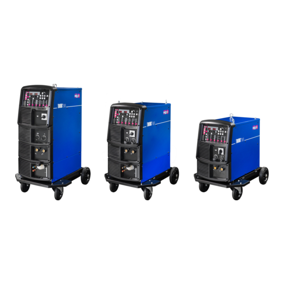
® ® ® 1 Identifikation iROB 501, iROB 401, iROB 1 Identifikation ® ® ® Die Schweißstromquellen iROB 501, iROB 401 und iROB 301 werden zum automatisierten MIG/MAG-Schweißen eingesetzt. Das Gerät darf nur mit Original Ersatzteilen betrieben werden. Diese ® ®... - Seite 5 ® ® ® iROB 501, iROB 401, iROB 1 Identifikation ® Abb. 2 Typenschild iROB ® Abb. 3 Typenschild iROB Das Gerät ist mit einem Typenschild gekennzeichnet. ► Für Rückfragen den Gerätetyp, die Gerätenummer und das Baujahr gemäß Typenschild bereithalten. DE - 5...
-
Seite 6: Verwendete Zeichen Und Symbole
® ® ® 2 Sicherheit iROB 501, iROB 401, iROB 1.3 Verwendete Zeichen und Symbole In der Betriebsanleitung werden folgende Zeichen und Symbole verwendet: Allgemeine Handlungsanweisungen. Handlungsschritte, die der Reihenfolge nach durchzuführen sind. Aufzählungen. Querverweissymbol verweist auf detaillierte, ergänzende oder weiterführende Informationen. Bildlegende, Positionsbezeichnung. -
Seite 7: Pflichten Des Betreibers
► Überprüfen Sie die Netzanschlussleitung regelmäßig auf Anzeichen einer Beschädigung oder Alterung. ► Verwenden Sie bei notwendig werdendem Ersatz der Netzanschlussleitung ausschließlich Original ABICOR BINZEL Ersatzteile. ► Lassen Sie die Netzanschlussleitung und den Netzstecker ausschließlich durch eine Elektrofachkraft austauschen. ► Stellen Sie beim Ersetzen des Netzsteckers und der Netzanschlussleitung den Spritzwasserschutz und die mechanische Festigkeit sicher. -
Seite 8: Lieferumfang
® ® ® 3 Lieferumfang iROB 501, iROB 401, iROB 3 Lieferumfang Die folgenden Komponenten sind im Lieferumfang enthalten: ® ® ® — 1× Schweißstromquelle iROB 501, iROB 401 oder iROB ® ® ® — 1× Betriebsanleitung Schweißstromquelle iROB 501, iROB 401 oder iROB —... -
Seite 9: Produktbeschreibung
® ® ® iROB 501, iROB 401, iROB 4 Produktbeschreibung 4 Produktbeschreibung 4.1 Aufbau und Funktion ® Abb. 4 Aufbau und Funktion iROB A Bedienfeld F Kühlgerät (optional) B Hauptschalter G Fahrwagen (optional) C Nicht belegt H Anschluss Stromrückleitung (bauteilseitig) D Anschluss Spannungsmessleitung I Nicht belegt E Anschluss Stromzuführung (schweißbrennerseitig) - Seite 10 ® ® ® 4 Produktbeschreibung iROB 501, iROB 401, iROB ® Abb. 6 Aufbau und Funktion iROB A Bedienfeld F Fahrwagen (optional) B Hauptschalter G Anschluss Stromrückleitung (bauteilseitig) C Nicht belegt H Nicht belegt D Anschluss Spannungsmessleitung I LED Netzkontrolle E Anschluss Stromzuführung (schweißbrennerseitig) Das Gerät ist Bestandteil eines automatisieren Schweißsystems.
-
Seite 11: Bedienelemente
® ® ® iROB 501, iROB 401, iROB 4 Produktbeschreibung 4.2 Bedienelemente Die Bedienelemente können je nach Produkttyp unterschiedlich ausgeprägt sein. Abb. 7 Bedienelemente A Linke Digitalanzeige P Taste <Heftzeit> B Rechte Digitalanzeige Q Taste <Lichtbogendynamik> C Drehknopf <Parametereinstellung> R Taste <Freigabe Startschweiß-/Endkraterparameter> D Taste <Umschaltung S Taste <Einbrandregelung>... - Seite 12 ® ® ® 4 Produktbeschreibung iROB 501, iROB 401, iROB Tab. 1 Bedienelemente Pos. Bezeichnung Funktion Drehknopf Passt den ausgewählten Parameterwert an (Schweißstrom, <Parametereinstellung> Schweißspannung und Drahtvorschubgeschwindigkeit). Taste <Umschaltung Auswahl Schweißstrom und Drahtvorschubgeschwindigkeit. Schweißstrom/Drahtvorschubg Der Wert wird in der linken Digitalanzeige angezeigt und kann eschwindigkeit>...
- Seite 13 ® ® ® iROB 501, iROB 401, iROB 4 Produktbeschreibung Tab. 1 Bedienelemente Pos. Bezeichnung Funktion Auswahltaste Gewünschtes Schweißverfahren auswählen. <Schweißverfahren> Die Auswahlmöglichkeit ist abhängig von den installierten Optionen. Die LED des angewählten Schweißverfahrens leuchtet auf. Einige Kombinationen aus Schweißdrahtdurchmesser, Schweißdrahtmaterial, Schweißgeschwindigkeit und Schutzgasarten sind nicht sinnvoll.
- Seite 14 ® ® ® 4 Produktbeschreibung iROB 501, iROB 401, iROB Tab. 1 Bedienelemente Pos. Bezeichnung Funktion Taste <Freigabe Startschweiß- Ermöglicht die Aktivierung von Startschweiß- und /Endkraterparameter> Endkraterparametern bei angewählter Betriebsart "Zweitakt" im automatisierten Betrieb (Interne Funktionen F45–47). Wenn die Taste gedrückt wird, leuchtet die LED und die Aktivierung von Schweißstart- und Endkraterparametern ist freigegeben.
- Seite 15 ® ® ® iROB 501, iROB 401, iROB 4 Produktbeschreibung Tab. 1 Bedienelemente Pos. Bezeichnung Funktion Taste <Enter> Führt die administrativen Funktionen wie Tastensperre, Passwort und Zuweisung von Schweißparametern zu Speicherplätzen aus. Wird die Taste für 3 Sekunden oder länger gedrückt, wir die Tastensperre aktiviert.
-
Seite 16: Wi-Fi Router Und Bedien-App (Optional)
® ® ® 4 Produktbeschreibung iROB 501, iROB 401, iROB 4.3 Wi-Fi Router und Bedien-App (optional) Abb. 9 Wi-Fi Router Wi-Fi Router Ist das Gerät mit einem optionalen Wi-Fi Router ausgestattet, können alle Funktionen des Geräts auch über ® die optionale Bedien-App iROB POWER App gesteuert und programmiert werden. -
Seite 17: Technische Daten
® ® ® iROB 501, iROB 401, iROB 4 Produktbeschreibung 4.4 Technische Daten Tab. 2 Umgebungsbedingungen Transport, Lagerung Temperatur der Umgebungsluft −20 °C bis +55 °C Relative Luftfeuchtigkeit 20 % bis 80 % (unkondensiert) gemäß EN IEC 60974-1 Tab. 3 Umgebungsbedingungen Betrieb Temperatur der Umgebungsluft −10 °C bis +40 °C... -
Seite 18: Transport Und Aufstellung
® ® ® 5 Transport und Aufstellung iROB 501, iROB 401, iROB 4.5 Anschlüsse Abb. 10 Anschlüsse Rückseite A Datenleitung W-LAN-Modul (Option) D Anschluss Zwischenschlauchpaket Schweißbrenner B Feldbusschnittstelle (z.B. Ehternet IP) E Anschluss Zwischenschlauchpaket MPP C Spannungsversorgung W-LAN-Modul (Option) 5 Transport und Aufstellung WARNUNG Verletzungsgefahr durch unsachgemäßes Transportieren und Aufstellen Bei unsachgemäßen Transportieren und Aufstellen kann das Gerät kippen oder herabstürzen. -
Seite 19: Inbetriebnahme
® ® ® iROB 501, iROB 401, iROB 6 Inbetriebnahme 6 Inbetriebnahme 6.1 Elektrischen Netzanschluss herstellen ► Sicherheitshinweise beachten. 2.4 Sicherheitshinweise zum elektrischen Netzanschluss auf Seite DE-8 WARNUNG Stromschlag durch unsachgemäßen elektrischen Netzanschluss Sind der elektrische Netzanschluss und die Erdung unsachgemäß installiert, kann es zu lebensgefährlichen Stromschlägen kommen. -
Seite 20: Anschluss An Übergeordnete Steuerung Herstellen
® ® ® 6 Inbetriebnahme iROB 501, iROB 401, iROB 6.3 Anschluss an übergeordnete Steuerung herstellen Die Anschlüsse für die externen Verbindungen befinden sich hinter der Abdeckplatte. Abb. 11 Anschlüsse externe Verbindungen A 4× Schrauben C Klemmleiste für externe Verbindungen B Abdeckplatte Schrauben (4×) lösen. -
Seite 21: F25 - F28: Externe Ausgänge Einstellen
® ® ® iROB 501, iROB 401, iROB 6 Inbetriebnahme 6.3.1 F25 - F28: Externe Ausgänge einstellen Funktionen von OUT-EXT1 (3 - 4) am Klemmenblock für den externen Anschluss einstellen Funktionen von OUT-EXT1 (5 - 6) am Klemmenblock für den externen Anschluss einstellen Funktionen von OUT-EXT1 (7 - 8) am Klemmenblock für den externen Anschluss einstellen... -
Seite 22: Beschreibung Einstellung
® ® ® 6 Inbetriebnahme iROB 501, iROB 401, iROB Beschreibung Einstellung 2 Das Kurzschließen der Klemmen startet den Drahtvorschub. Beschreibung Einstellung 3 Wird nach dem Kurzschließen der Klemmen ein Drahtvorschub ausgelöst, wird der Schweißdraht zurückgezogen. Die Klemmen müssen kurzgeschlossen sein, bevor das Drahtvorschubsignal kommt. Um die Operation zu stoppen, muss zunächst der Drahtvorschubsignal abgeschaltet und anschließend die Klemmen geöffnet werden. -
Seite 23: Schweißverfahren
® ® ® iROB 501, iROB 401, iROB 6 Inbetriebnahme Beispiel 3: Auslesen der Schweißparameter aus JOB Nr. 7 F30 und F31 auf 5 setzen. Signal der externen Eingangsklemmen IN-EXT2/IN-EXT3 auf ON schalten. JOB Nr. 7 auslesen. Für F29 und F32 können andere Funktionen verwendet werden. Selbst nach dem Auslesen der Schweißparameter über diese Funktion kann das Schweißverfahren entweder über das Bedienfeld der Maschine oder durch „DC/Puls Umschaltung“... - Seite 24 ® ® ® 6 Inbetriebnahme iROB 501, iROB 401, iROB Beschreibung Einstellung 9 Das Kurzschließen der Klemmen verschiebt die vorherige JOB Nr. Die JOB Nr. wird zur vorherigen Nr. geschoben und dieser Parametersatz wird ausgelesen wenn die Klemmen während des Schiebemodus für 100 ms kurzgeschlossen werden. Denn die JOB Nr. den niedrigsten Wert erreicht hat, springt sie auf den höchsten Wert weiter.
-
Seite 25: Betrieb
Das Passwort muss eine dreistellige Zahl sein. „000“ wird nicht als Passwort akzeptiert. ► Passwort notieren und sicher verwahren. Ein verloren gegangenes Passwort kann nur durch ABICOR BINZEL zurückgesetzt werden. ► Um die Passworteinstellung abzubrechen, Hauptschalter auf <0> stellen. Hauptschalter auf <0> stellen. -
Seite 26: Passwortschutz Aktivieren
® ® ® 7 Betrieb iROB 501, iROB 401, iROB Zehner- und Einerstelle in gleicher Weise am Drehknopf <Parametereinstellung> einstellen. Passwort prüfen und 2× Taste <Enter> drücken. Das Passwort ist gespeichert. Passwortschutz aktivieren Taste <Enter> für mehr als 3 Sekunden drücken. Passwortschutz ist aktiv. -
Seite 27: Bedienfeldsperre Aktivieren
0 bis 10 s 0,1 s Definiert die Dauer des Gasflusses vor dem Schweißstart. Startschweiß- Strom 20 bis 550 A Startschweißparameter: parameter (iROB 501) Definiert Schweißstrom/Spannung unmittelbar nach dem Schweißstart. 20 bis 400 A Hauptschweiß- ® (iROB 401) Hauptschweißparameter: parameter Definiert Schweißstrom/Spannung... -
Seite 28: Übersicht Der Schweißverfahren
® ® ® 7 Betrieb iROB 501, iROB 401, iROB Tab. 10 Funktionen Funktion Einstellbare Parameter Endkraterfüllen Endkraterfüllen-OFF Endkraterfüllen-ON (ohne Puls) Endkraterfüllen-ON (mit Puls) Schutzgasart MAG (18 % CO MAG (8 % CO MIG (2 % O MIG (2,5 % CO MIG (100 % Ar) MIG (30 % He) Schweißdrahtmaterial... - Seite 29 ® ® ® iROB 501, iROB 401, iROB 7 Betrieb Tab. 11 Schweißverfahren (Standard) Schweißverfahren Schutzgasart Schweißdraht- Schweißdraht- Schweiß- Einbrand- material durchmesser (mm) geschwindig- regelung keit 1,6 mm nicht bei ® iROB 301 verfügbar iArc mC Clean 100% CO 0,8 / 1,0 / 1,2 Standard –...
-
Seite 30: Schweißvorgang Vorbereiten
® ® ® 7 Betrieb iROB 501, iROB 401, iROB 7.3 Schweißvorgang vorbereiten 4.2 Bedienelemente auf Seite DE-12 Vor dem Schweißvorgang müssen die folgende Einstellung vorgenommen werden: Prüfen, ob das Schweißverfahren zu dem zu schweißenden Schweißdrahtmaterial passt. 7.2.2 Übersicht der Schweißverfahren auf Seite DE-29 Schweißdrahtmaterial, Schutzgasart und Schweißgeschwindigkeit einstellen. -
Seite 31: Schweißabfolge Einstellen
® ® ® iROB 501, iROB 401, iROB 7 Betrieb 7.3.2 Schweißabfolge einstellen Abb. 8 Übersicht LEDs auf Seite DE-16 Eine Schweißabfolge besteht aus den Sequenzen Gasvorströmen, Hauptschweißparameter und Gasnachströmen. Zu einer Sequenz kann in Abhängigkeit von der Endkratereinstellung der Startschweißparameter und der Endkraterfüllparameter hinzugefügt werden. -
Seite 32: Schweißstrom Einstellen
® ® ® 7 Betrieb iROB 501, iROB 401, iROB Gasvor- und Gasnachströmzeit einstellen Taste <Parameteranwahl> so oft drücken bis die LED <Gasvorströmen> oder <Gasnachströmen> ausgewählt ist. Am Drehknopf <Parametereinstellung> die Gasströmzeit einstellen. Der Wert wird in der linken Digitalanzeige angezeigt. -
Seite 33: Schweißspannung Einstellen
® ® ® iROB 501, iROB 401, iROB 7 Betrieb Schweißspannung einstellen Taste <Parameteranwahl> so oft drücken bis die LED <Hauptschweißparameter>, <Startschweißparameter> oder <Endkraterfüllparameter> ausgewählt ist. ± m/min. Prüfen, ob die LED <V> (Volt) leuchtet. Falls nicht, Taste <Umschaltung Spannung> drücken. ±... -
Seite 34: Zusätzliche Funktionen
® ® ® 7 Betrieb iROB 501, iROB 401, iROB 7.4 Zusätzliche Funktionen 7.4.1 Lichtbogencharakteristik einstellen Die Verwendung dieser Funktion ermöglicht die Anpassung des Lichtbogens von hart (−10) auf weich (+10). ARC DYN. Taste <Lichtbogenregelung> drücken. Der Wert wird in der linken Digitalanzeige angezeigt. Am Drehknopf <Parametereinstellung>... -
Seite 35: Interne Funktionen Einstellen
® ® ® iROB 501, iROB 401, iROB 7 Betrieb 7.5 Interne Funktionen einstellen Interne Funktionen bieten zusätzliche Anpassungsmöglichkeiten der Schweiß- und/oder Geräteparameter und können vom Anwender entsprechend der Anforderungen angepasst werden. Die internen Funktionen werden mit dem Einstellen oder Ändern eines Wertes aktiviert. 7.5.1 Einstellungen vornehmen Taste <Funktion>... -
Seite 36: F34: Einschnürungserkennungssensibilität Automatisch Korrigieren
® ® ® 7 Betrieb iROB 501, iROB 401, iROB Tab. 13 Übersicht der internen Funktionen. Nr. / Funktionsname Einstellbereich Startwert F33: Sperrverhältnis für die Einschnürerkennung – – anzeigen ® (nicht bei iROB 301 verfügbar) F34: Einschnürungserkennungssensibilität ON/OFF automatisch korrigieren ®... - Seite 37 ® ® ® iROB 501, iROB 401, iROB 7 Betrieb F3: Wärmeintragsanzeige umschalten Der Ausgangsstrom / die Ausgangsspannung und der Wärmeeintrag werden nach Abschluss des Schweißvorgangs blinkend angezeigt. Einstellbereich ON/OFF Defaultwert Speichermöglichkeit Nein Beschreibung ON: Zeigt den Wärmeeintrag an. OFF: Zeigt den Wärmeeintrag nicht an. Der Wärmeeintrag wird in der Digitalanzeige wie folgt angezeigt: Rechte Digitalanzeige Bereich des Wärmeeintrags...
-
Seite 38: Defaultwert 0 A Speichermöglichkeit
® ® ® 7 Betrieb iROB 501, iROB 401, iROB F14/F15: Startregelung (Zeit und Strom) anpassen Abhängig von den Schweißparametern und dem eingestellten Schweißstromwert, wird die entsprechende Zeit und der Strom für die Startregelung ermittelt. Wenn der korrekte Rückbrand während des Startvorgangs nicht eintritt, muss der Strom und die Zeit entsprechend angepasst werden. - Seite 39 ® ® ® iROB 501, iROB 401, iROB 7 Betrieb F19: Alarmabschaltung einstellen Wenn ein Alarm auftritt, kann die Stromausgabe der Schweißstromquelle unterbrochen werden. Bei einigen Alarmcodes ist es möglich weiterzuschweißen, selbst wenn ein Alarm entdeckt wurde. Dies kann dazu führen das eine Alarmanzeige ignoriert wird.
- Seite 40 ® ® ® 7 Betrieb iROB 501, iROB 401, iROB F24: Drahtvorschubgeschwindigkeit einstellen Funktion ON: Der Schweißstrom wird basierend auf der Drahtvorschubgeschwindigkeit automatisch eingestellt, auch wenn das Schweißverfahren über die Auswahltaste <Schutzgasart> geändert wird. Jedes mal wenn die Taste <Parameteranwahl> gedrückt wird, schaltet die Anzeige von Drahtvorschubgeschwindigkeit auf Schweißstrom um und umgekehrt.
-
Seite 41: F33: Sperrverhältnis Für Die Einschnürerkennung Anzeigen
® ® ® iROB 501, iROB 401, iROB 7 Betrieb F33: Sperrverhältnis für die Einschnürerkennung anzeigen Jede Verschiebung in der Einschnürerkennung führt zu vermehrter Spritzerbildung. Diese Funktion ermöglicht es das Sperrverhältnis für die Einschnürerkennung vom Schweißstart bis zum Schweißende zu prüfen. -
Seite 42: F35: Einschnürungserkennungssensibilität Speichern
® ® ® 7 Betrieb iROB 501, iROB 401, iROB F35: Einschnürungserkennungssensibilität speichern Definiert ob die durch Funktion automatisch korrigierte Einschnürungserkennungssensibilität nach dem Ende des Schweißvorgang auf den voreingestellten Wert zurückgesetzt wird. Interne Funktionen F36/F37 einstellen. Interne Funktion F34 aktivieren. Wenn das freie Schweißdrahtende und die Schweißbedingungen zwischen den Schweißvorgängen starken Änderungen unterworfen sind, diese Funktion ausschalten. -
Seite 43: F45/F46/F47: Spezielle Endkraterfüllsequenz
® ® ® iROB 501, iROB 401, iROB 7 Betrieb F43: CAN ID Wenn mehrere Schweißstromquellen an ein PC Überwachungssystem angeschlossen sind, kann hier die ID für den CAN Bus eingestellt werden. Einstellbereich 1 bis 16 Defaultwert Speichermöglichkeit Nein Beschreibung Definiert die CAN ID Nummer die mit dem PC Überwachungssystem usw. -
Seite 44: Defaultwert 0 S Speichermöglichkeit
® ® ® 7 Betrieb iROB 501, iROB 401, iROB Einstellbereich 0 bis 10 s Defaultwert Speichermöglichkeit Beschreibung F46: Definiert die Zeit des Startstroms. (Aktiv wenn F45 auf ON gesetzt ist.) Einstellbereich 0 bis 10 s Defaultwert Speichermöglichkeit Beschreibung F47: Definiert die Endkraterfüllzeit. (Aktiv wenn F45 auf ON gesetzt ist.) F52: Datentypen der DatenLOG-Funktion Diese Funktion ermöglicht es Daten auszuwählen die mit der DatenLOG-Funktion abgespeichert werden können. - Seite 45 ® ® ® iROB 501, iROB 401, iROB 7 Betrieb F53: Abtastrate für die DatenLOG Funktion einstellen Tab. 15 Abtastrate für die DatenLOG-Funktion Einstellung Abtastintervall 10 ms 100 ms Einstellbereich 1 bis 3 Defaultwert Speichermöglichkeit Nein Beschreibung Abtastgeschwindigkeit der DatenLOG-Funktion definieren F60: Pulsspitzenstrom feinanpassen Diese Funktion ermöglicht die Feineinstellung des Standard Pulsspitzenstroms.
- Seite 46 ® ® ® 7 Betrieb iROB 501, iROB 401, iROB F63: Pulsspitzenstroms in der Niedrigpulsphase feinanpassen Diese Funktion erlaubt die Feinanpassung des Standardpulsspitzenstroms beim iArc mX Move DC- Schweißverfahren auf der „Niedrig“ Seite. Einstellbereich −150 bis +150 A Defaultwert Speichermöglichkeit Beschreibung Definiert den Anpasswert des Pulsspitzenstroms in der Niedrigpulsphase.
- Seite 47 ® ® ® iROB 501, iROB 401, iROB 7 Betrieb F67: Anwahl der Stromwerte (Startschweißparameter, Endkraterparameter) einstellen Wenn die Endkraterfüllfunktion eingeschaltet wird, kann der Stromwert für den Startparameter und den Endkraterparameter basierend auf dem aktuellen Wert des Schweißstroms in den Funktionen F68 und F69 in % eingestellt werden.
-
Seite 48: Jobspeicher Verwalten
® ® ® 7 Betrieb iROB 501, iROB 401, iROB 7.6 Jobspeicher verwalten 7.6.1 Job speichern Es können bis zu 100 Jobs abgespeichert und bei Bedarf wieder aufgerufen werden. Ein Job kann die folgenden Informationen enthalten: — Verwendeter Schweißmodus (Schutzgasart, Schweißdrahtmaterial, Schweißdrahtdurchmesser, Endkraterbehandlung, Einbrandregelung iArc mX Speed usw.) —... -
Seite 49: Job Ändern
® ® ® iROB 501, iROB 401, iROB 7 Betrieb 7.6.2 Job ändern Taste <Parameteranwahl> drücken. Die gespeicherten Werte werde werden in der linken/rechten Digitalanzeige blinkend angezeigt. Werte entsprechend anpassen. Um die JOB Nr. zu ändern, Taste <Speichern> drücken. Die Anzeige wechselt auf den folgenden Status: ... -
Seite 50: Job Löschen
® ® ® 7 Betrieb iROB 501, iROB 401, iROB 7.6.4 Job löschen Gelöschte Daten können nicht wieder hergestellt werden. Hauptschalter auf <0> stellen. Tasten <Speichern> und <Laden> gleichzeitig gedrückt halten und Hauptschalter wieder auf <I> stellen. Beide Tasten weiter gedrückt halten bis in der linken Digitalanzeige <dEL>... -
Seite 51: Schweißvorgang Durchführen
® ® ® iROB 501, iROB 401, iROB 7 Betrieb 7.7 Schweißvorgang durchführen 7.7.1 Schweißvorgang starten Korrekte Einstellung der Schweißparameter prüfen. "Schweißen Start"-Signal aktivieren. Während des Schweißens wird der Schweißstrom auf der linken Digitalanzeige und die Schweißspannung auf der rechten Digitalanzeige in Echtzeit angezeigt. Diese Anzeige ist der Durchschnittswert der letzten Sekunde. -
Seite 52: Softwareversion Prüfen
® ® ® 7 Betrieb iROB 501, iROB 401, iROB Tasten gedrückt halten, bis in beiden Digitalanzeigen <End> angezeigt wird. Die Initialisierung startet. Wenn in beiden Digitalanzeigen <End> angezeigt wird, Hauptschalter auf <0> stellen. ± m/min. sec. Die LED Netzkontrolle erlischt. Die Werkseinstellung ist JOB.No. -
Seite 53: Außerbetriebnahme
® ® ® iROB 501, iROB 401, iROB 8 Außerbetriebnahme 8 Außerbetriebnahme Hauptschalter auf <0> stellen. Gerät von der Stromversorgung trennen. Gerät von der Schutzgasversorgung trennen. 9 Wartung und Reinigung Regelmäßige Wartung und Reinigung sind Voraussetzung für eine lange Lebensdauer und eine einwandfreie Funktion. -
Seite 54: Wartungs- Und Reinigungsintervalle
® ® ® 9 Wartung und Reinigung iROB 501, iROB 401, iROB 9.1 Wartungs- und Reinigungsintervalle Die angegebenen Intervalle sind Richtwerte und beziehen sich auf den Einschichtbetrieb. Wir empfehlen über die Prüfungen Buch zu führen. Daraus muss das Datum der Überprüfung, festgestellte Mängel und der Name des Überprüfenden ersichtlich sein. -
Seite 55: Störungen Und Deren Behebung
10 Störungen und deren Behebung 10 Störungen und deren Behebung ► Dokumentation der schweißtechnischen Komponenten beachten. ► Bei Fragen und Problemen an einen entsprechenden Fachhändler oder an ABICOR BINZEL wenden. 10.1 Allgemeine Störungen Tab. 18 Allgemeine Störungen und deren Behebung Störung... -
Seite 56: Störungen Am Bedienfeld
® ® ® 10 Störungen und deren Behebung iROB 501, iROB 401, iROB Tab. 18 Allgemeine Störungen und deren Behebung Störung Ursache Behebung Schweißdraht wird nicht Gegendruckrolle liegt nicht an. ► Andruckrolle korrekt einstellen. gefördert. Es wird keine Störung in der Drahtführung. ►... - Seite 57 ® ® ® iROB 501, iROB 401, iROB 10 Störungen und deren Behebung Tab. 19 Fehlercodes am Bedienfeld und deren Behebung Fehlercode Art der Störung Störungsursache Maßnahme 1 = Alarm 2 = Warnung 030 bis Installation der Software von ► Prüfen, ob die USB Quelle funktionsfähig und richtig einer USB Quelle ist eingesteckt ist.
- Seite 58 ® ® ® 10 Störungen und deren Behebung iROB 501, iROB 401, iROB Tab. 19 Fehlercodes am Bedienfeld und deren Behebung Fehlercode Art der Störung Störungsursache Maßnahme 1 = Alarm 2 = Warnung Fehler in den gespeicherten Es kann sein, dass die spezifizierten Schweißparameter und Backupdaten.
-
Seite 59: Demontage
Lappen usw.) müssen ebenfalls entsprechend den Angaben des Betriebsmittelherstellers entsorgt werden. ► Örtliche Bestimmungen und Hinweise zur Entsorgung der vom Betriebsmittelhersteller vorgegebenen Sicherheitsdatenblätter beachten. 12.3 Verpackungen ABICOR BINZEL hat die Transportverpackung auf das Notwendigste reduziert. Bei der Auswahl der Verpackungsmaterialien wird auf eine mögliche Wiederverwertung geachtet. DE - 59... -
Seite 60: Feldbusverbindungstool Ifr-800
® ® ® 13 Feldbusverbindungstool IFR-800 iROB 501, iROB 401, iROB 13 Feldbusverbindungstool IFR-800 13.1 Konfiguration Das Feldbusverbindungstool entspricht den folgenden Kommunikationsstandards. Der Typ des Feldbusverbindungstools hängt jeweils vom verwendeten Kommunikationsstandard ab. Tab. 20 Konfiguration Feldverbindungstool IFR-800 Feldbus Typ des Feldverbindungstools EtherNet/IP IFR-800EI PROFIBUS... -
Seite 61: Devicenet
® ® ® iROB 501, iROB 401, iROB 13 Feldbusverbindungstool IFR-800 PROFIBUS Tab. 22 Grundlegende Eigenschaften PROFIBUS Kommunikationsstandard PROFIBUS-DP Baudrate Unterstützung aller üblichen Baudraten bis 12 MBit/s (automatische Erkennung) Verbindungsstück IEC 61076-2-101, M12, 5-polig, B-codiert, Buchse Knotenadresse Voreinstellung: 77 Die Einstellung kann mit dem Konfigurationsschalter von Anybus Communicator AB7000 vorgenommen werden. -
Seite 62: Verarbeitungszeit Für Kommunikationsdaten
® ® ® 13 Feldbusverbindungstool IFR-800 iROB 501, iROB 401, iROB PROFINET-IRT Tab. 24 Grundlegende Eigenschaften PROFINET-IRT Kommunikationsstandard PROFINET-IRT Bandbreite 10/100 MBit/s Verbindungsstück IEC 61076-2-101, M12, 4-polig, D-codiert, Buchse IP-Adresse Voreinstellung: 192.168.0.2 Um die IP-Adresse zu ändern, muss ein Arbeitsplatzrechner, auf dem eine spezielle Software installiert ist, über Ethernet mit der Schweißstromquelle verbunden werden. -
Seite 63: Anwendungsspezifikationen
® ® ® iROB 501, iROB 401, iROB 13 Feldbusverbindungstool IFR-800 13.4 Anwendungsspezifikationen Der folgende Abschnitt enthält eine Beschreibung der Ausgangsdaten, die von externen Geräten (Master) an den Schweißautomaten (Slave) gesendet werden, sowie eine Beschreibung der Eingangsdaten, die vom Schweißautomaten (Slave) an externe Geräte (Master) gesendet werden. 13.4.1 Liste der E/A-Daten Tab. - Seite 64 ® ® ® 13 Feldbusverbindungstool IFR-800 iROB 501, iROB 401, iROB Tab. 25 Liste der Ausgangsdaten Byte Bit 7 Bit 6 Bit 5 Bit 4 Bit 3 Bit 2 Bit 1 Bit 0 Anzeige- Funktion (Port 4) Nr. änderung (7-Bit-Ganzzahl ohne Vorzeichen) Funktion (Port 4) Einstellwert (16-Bit-Ganzzahl mit Vorzeichen) –...
-
Seite 65: Handhabung Von Ganzzahlen
® ® ® iROB 501, iROB 401, iROB 13 Feldbusverbindungstool IFR-800 Tab. 26 Liste der Eingangsdaten Byte Bit 7 Bit 6 Bit 5 Bit 4 Bit 3 Bit 2 Bit 1 Bit 0 Funktion (Port 2) Einstellwert (16-Bit-Ganzzahl mit Vorzeichen) Anzeige- Funktion (Port 3) Nr. - Seite 66 ® ® ® 13 Feldbusverbindungstool IFR-800 iROB 501, iROB 401, iROB Tab. 27 Vereinfachte Tabelle für Ausgangsdaten Offset Funktion Beschreibung 4–5 – Schweißmodus 0–1 VERFAHR- Wählt die Verfahrgeschwindigkeit aus. GESCHWINDIGKEIT Tab. 31 Einstellung der Verfahrgeschwindigkeit auf Seite DE-73 2–4 SCHWEISSMETHODE Wählt ein Schweißverfahrens aus.
-
Seite 67: Beispiel Für Die Einstellung Von Ausgangsdaten
® ® ® iROB 501, iROB 401, iROB 13 Feldbusverbindungstool IFR-800 13.4.3 Beispiel für die Einstellung von Ausgangsdaten Das folgende Beispiel veranschaulicht die Einstellungsmethode zum Ersetzen der einzelnen Arbeitsvorgänge im Gerät mit Übertragungsdaten (Ausgangsdaten) von einem externen Gerät. Tab. 28 Beispiel für die Einstellung von Ausgangsdaten Arbeitsvorgang Einstellungsmethode... -
Seite 68: Details Der E/A-Daten
® ® ® 13 Feldbusverbindungstool IFR-800 iROB 501, iROB 401, iROB Tab. 28 Beispiel für die Einstellung von Ausgangsdaten Arbeitsvorgang Einstellungsmethode Einstellung für Feinjustierung Zum Einstellen der Feinjustierung der Schweißspannung für der Schweißspannung für synergetischen Modus auf „−10“ Offset 15 auf synergetischen Modus „−10 (= 0 ×... - Seite 69 ® ® ® iROB 501, iROB 401, iROB 13 Feldbusverbindungstool IFR-800 Tab. 29 Details der Ausgangsdaten Byte Funktion Beschreibung – Speicherplatznummer Wird festgelegt, wenn die Speicherfunktion für Schweiß- für Schweißbedingung bedingungen (Jobspeicher) verwendet wird. (Jobspeicher) 7.6 Jobspeicher verwalten auf Seite DE-49 Wird diese Funktion nicht verwendet, wird der Wert auf 0 festgelegt.
- Seite 70 ® ® ® 13 Feldbusverbindungstool IFR-800 iROB 501, iROB 401, iROB Tab. 29 Details der Ausgangsdaten Byte Funktion Beschreibung 4–5 – Kennlinienauswahl Legt die Kennlinie fest. Wenn eine nicht vorhandene Schweißmoduskombination festgelegt wird, wird eine Warnung ausgegeben und es bleibt der Schweißmodus bestehen, der wirksam war, bevor die Einstellung vorgenommen wurde.
- Seite 71 ® ® ® iROB 501, iROB 401, iROB 13 Feldbusverbindungstool IFR-800 Tab. 29 Details der Ausgangsdaten Byte Funktion Beschreibung Spannungseinstellung Bei Einstellung auf 1 wird der synergetische Modus für für synergetischen die Spannungseinstellung verwendet. Modus Schweißspannung einstellen auf Seite DE-34 Darüber hinaus werden die Spannungseinstellungen der Offsets 13 und 14 deaktiviert und Offset 15 für die Feinjustierung der Schweißspannung im synergetischen...
-
Seite 72: Verfahrgeschwindigkeit
® ® ® 13 Feldbusverbindungstool IFR-800 iROB 501, iROB 401, iROB Tab. 29 Details der Ausgangsdaten Byte Funktion Beschreibung 0–6 Funktion (Port 1) Nr. Hier werden Einstellungen außer den Offsets 4 bis 17 festgelegt. Es gibt 4 Einstellungsports, sodass bis zu Funktion (Port 1) 4 Einstellungen gleichzeitig geändert werden können. -
Seite 73: Schweißdrahtmaterial
® ® ® iROB 501, iROB 401, iROB 13 Feldbusverbindungstool IFR-800 Tab. 33 Einstellung der Schutzgasart Einstellung Schutzgasart 80/20 ArCO 98/2 ArO 90/10 ArCO 97,5/2,5 ArCO 70/30 ArHe Option Tab. 34 Einstellung des Schweißdrahtmaterials Einstellung Schweißdrahtmaterial Fe (Fülldraht) CrNi CrNi (Ferr) CrNi (Fülldraht) AlMg5 AlSi5/12... - Seite 74 ® ® ® 13 Feldbusverbindungstool IFR-800 iROB 501, iROB 401, iROB Tab. 37 Details der Eingangsdaten Offset Funktion Beschreibung Schweißstart Wird 1, wenn das Schweißstartsignal erkannt wird. Drahtvorschub Wird 1, wenn Drahtvorschub tatsächlich durchgeführt wird. Drahtrückzug Wird 1, wenn der Drahtrückzug tatsächlich durchgeführt wird.
- Seite 75 ® ® ® iROB 501, iROB 401, iROB 13 Feldbusverbindungstool IFR-800 Tab. 37 Details der Eingangsdaten Offset Funktion Beschreibung – Lichtbogencharakteristik Die derzeit aktivierte Einstellung wird festgelegt. – EN-Verhältnis Spannungseinstellung für synergetischen Modus Einstellung für Draht- vorschubgeschwindig- keit Einstellung für Drahtvorschub- geschwindigkeit Angezeigter Messwert Im Schweiß-, Drahtvorschub- und Drahtrückzugsmodus...
-
Seite 76: Funktionen
® ® ® 13 Feldbusverbindungstool IFR-800 iROB 501, iROB 401, iROB Tab. 38 Fehlercodes Fehlercode Beschreibung 1004 Sendefehler vom Steuerteil des Geräts zur Feldbuskommunikationseinrichtung 1101 Schweißmoduswarnung. Der angegebene Schweißmodus ist nicht vorhanden. 1102 Warnung für Speicherplatznummer. Es wurde eine Speicherplatznummer außerhalb des gültigen Bereichs angegeben oder es wird versucht, eine Schweißbedingung zu laden, die nicht gespeichert wurde. - Seite 77 ® ® ® iROB 501, iROB 401, iROB 13 Feldbusverbindungstool IFR-800 Tab. 39 Funktionsnummern Funktionsname Einstellbereich Vorgabewert Beschreibung Anfangsstrom 20–550 Legt den Strom in der Anfangsbedingung fest. Die Einheit dieser Einstellung ist [1 A]. Diese Einstellung ist nur gültig, wenn die spezielle Endkraterfüllsequenzfunktion (F45) ON ist und die Einstellung für Drahtvorschubgeschwindigkeit von...
- Seite 78 ® ® ® 13 Feldbusverbindungstool IFR-800 iROB 501, iROB 401, iROB Tab. 39 Funktionsnummern Funktionsname Einstellbereich Vorgabewert Beschreibung Feinjustierung der −100–100 Führt eine Feinjustierung der Endkraterspannung für Endkraterspannung für den synergetischen synergetischen Modus Modus durch. Diese Einstellung ist nur gültig, wenn die spezielle Endkraterfüllsequenzfunktion (F45) ON ist und die Spannungseinstellung für synergetischen...
-
Seite 79: Zeitablauf Der Regelung
® ® ® iROB 501, iROB 401, iROB 13 Feldbusverbindungstool IFR-800 13.4.6 Zeitablauf der Regelung Gasvorströmen/Gasnachströmen Der Zeitablauf für Schweißstart und Gasvorströmen/Gasnachströmen entspricht normalerweise dem beschriebenen Zeitablauf wenn kein Endkrater eingestellt ist. Wenn allerdings die Gasspülung vor dem Schweißstart aktiviert wurde und der Schweißstart aktiviert wird, ohne die Gasspülung zu deaktivieren, entfällt der Vorströmzeitraum und die Spannung liegt sofort am Ausgang an. -
Seite 80: Zubehörteile
® ® ® 14 Zubehörteile iROB 501, iROB 401, iROB Schweißstart Start- Leerlauf Gasvor- Unbelasteter Schweißen Vermeidung Beseitigen Gasnach- Leerlauf regelung strömen Ausgang strömen Drahtfest- Drahtfest- brand brand Sequenz Schweißstart Gasspülung Inverterausgang (Spannungs- ausgang) (Stromausgang) zulässig nicht zulässig zulässig Drahtvorschub/Drahtrückzug/ Schweißerkennung zulässig/nicht zulässig 14 Zubehörteile... - Seite 81 ® ® ® iROB 501, iROB 401, iROB Notizen Notizen DE - 81...