Abicor Binzel MB-15 Betriebsanleitung
Mig/mag schweißbrenner
Inhaltsverzeichnis
Verfügbare Sprachen
Verfügbare Sprachen
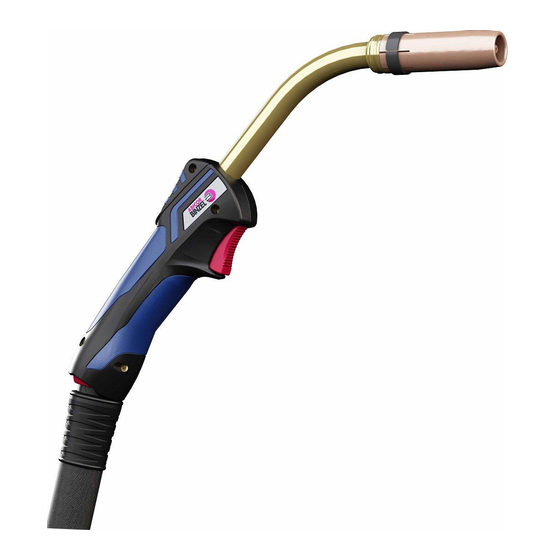
MIG/MAG Schweißbrenner
MB / AUT / RAB / PP
EN 60 974-7
Betriebsanleitung
Operating instructions
Mode d´emploi
Instructivo de servicio
MIG/MAG Welding torch
MB / AUT / RAB / PP
EN 60 974-7
MIG/MAG Torches de Soudage
MB / AUT / RAB / PP
EN 60 974-7
MIG/MAG Antorcha de soldadura
MB / AUT / RAB / PP
EN 60 974-7
Kapitel
Inhaltsverzeichnis

Verwandte Anleitungen für Abicor Binzel MB-15


Inhaltszusammenfassung für Abicor Binzel MB-15
- Seite 1 Betriebsanleitung Operating instructions Mode d´emploi Instructivo de servicio MIG/MAG Schweißbrenner MIG/MAG Welding torch MB / AUT / RAB / PP MB / AUT / RAB / PP EN 60 974-7 EN 60 974-7 MIG/MAG Torches de Soudage MB / AUT / RAB / PP EN 60 974-7 MIG/MAG Antorcha de soldadura MB / AUT / RAB / PP...
- Seite 2 Inhalt Deutsch ....... Seite 3 Contents Der Hersteller behält sich das Recht vor, jederzeit und ohne vorherige Mittei- Sommaire lung Änderungen an dieser Betriebsanleitung durchzuführen, die durch Druck- Indice...
-
Seite 3: Inhaltsverzeichnis
1. Inhalt Inhalt Seite Bestimmungsgemäße Verwendung Seite Technische Daten Seite Lieferumfang Seite Sicherheitshinweise Seite 5.1 Erklärungen Seite 5.2 Kennzeichnung des Schweißbrenners Seite 5.3 Begriffserklärung Seite 5.4 Sicherheitsnorm Seite 5.5 Sicherheitsprüfungen Seite 5.6 Pflichten des Betreibers Seite Gefahrenhinweise Seite Transport und Verpackung Seite Funktion Seite... -
Seite 4: Bestimmungsgemäße Verwendung
Für die flüssiggekühlten Ausführungen ist ein Umlaufkühlaggregat erforderlich. Standardausführung ist der Handgriff ERGO mit Steuereinrichtung für max. 42 V und 0,1 bis 1 A. Die Schweißbrenner dürfen nur mit Original ABICOR BINZEL ® -Ersatzteilen betrieben werden. Der Betreiber hat sicherzustellen, dass der Schweißbrenner in Verbindung mit dem Schweißgerät der EG-Richtlinie EMV... - Seite 5 3. Technische Daten Allgemeine Brennerdaten nach EN 60 974-7 (Fortsetzung) Spannungsart: Gleichspannung DC Polung der Elektroden: in der Regel positiv Drahtarten: handelsübliche Runddrähte Führungsart: handgeführt maschinengeführt Spannungsbemessung: 113 V Scheitelwert 141 V Scheitelwert Schutzart der maschinenseitigen Anschlüsse (EN 60 529): IP3X IP2X Schutzgas:...
-
Seite 6: Lieferumfang
4. Lieferumfang Die Schweißbrenner dieser Baureihe werden als vollständige Einheit schweiß- bereit ausgeliefert, d. h. mit Schlauchpaket und Zentralstecker. Prüfen Sie, ob Sie die korrekten Ausrüstteile zur Erstbestückung gewählt haben. Details zu Ausrüst- und Verschleißteilen, sowie die Bestelldaten und Identnummern entnehmen Sie bitte den aktuellen Bestellunterlagen. Betriebsanleitung für MB / AUT / RAB und PP : Lesen Sie bitte die ganze Betriebsanleitung durch, damit Sie die Gewähr für einen störungs- und gefährdungsfreien Betrieb haben. -
Seite 7: Sicherheitsnorm
Handschweißbrenner mit integrierter 5. Sicherheits- Rauchgasabsaugung hinweise RAB ... D Handschweißbrenner mit integrierter (Fortsetzung) Rauchgasabsaugung und mit auswechselbarem Düsenstock Hand-Push-Pull-Schweißbrenner mit integriertem Antrieb PP ... D Hand-Push-Pull-Schweißbrenner mit integriertem Antrieb und mit auswechselbarem Düsenstock 5.4 Sicherheitsnorm Der MIG/MAG Schweißbrenner wurde entsprechend der deutschen Fassung der Vorschrift EN 60 974-7 gebaut. -
Seite 8: Transport Und Verpackung
6. Gefahren- • Ziehen Sie das Schlauchpaket nicht über scharfe Kanten oder hinweise legen es im Spritzerbereich oder auf heißen Werkstücken ab. (Fortsetzung) • Schützen Sie unbeteiligte Personen durch Schutzvorhänge oder Schutzwände gegen optische Strahlung und Blendgefahr. • Entnehmen Sie die Handhabung von Gasflaschen den Anweisungen der Gasehersteller und der Druckgasverordnung. -
Seite 9: Funktion
8. Funktion Der gebrauchsfähige MIG/MAG Schweißbrenner besteht aus: 1. Schlauchpaket mit Ausrüstung 2. Handgriff / Griffrohr bei AUT Versionen 3. Brennerhals z. B. MB 240 D mit Ausrüst- und Verschleißteilen Alle Elemente bilden zusammen eine funktionsfähige Einheit, die mit entspre- chenden Betriebsmitteln versorgt, einen Lichtbogen zum Schweißen erzeugt. -
Seite 10: Schlauchpaket Maschinenseitig Montieren
Rücklaufes am Umlaufkühlaggregat. Kühlmittelvorlauf – blau markierter Stecknippel Kühlmittelrücklauf – rot markierter Stecknippel Kühlmittelempfehlung: ABICOR BINZEL ® BTC-15 Entlüften Sie bei jeder Erstinbetriebnahme bzw. nach jedem Schlauchpaket- wechsel das gesamte Kühlsystem wie folgt: 1. Lösen Sie am laufenden Umlaufkühlaggregat den Schlauch vom Kühlmittel- rücklauf und halten diesen über einen Auffangbehälter. -
Seite 11: Bedienung
10. Bedienung Überprüfen Sie – das Schlauchpaket vor dem Anschließen an das Drahtvorschubgerät, ob entsprechend dem Drahtdurchmesser und der Drahtart die geeignete Drahtführung – Führungsspirale oder Kunststoffseele – eingesetzt ist. – die Ausrüstteile im Brennerhals, ob entsprechend dem Drahtdurchmesser und der Drahtart die richtige Kontaktdüse eingesetzt ist. -
Seite 12: Wartung / Reinigung
Schlauchpaket – Prüfen Sie alle Verschraubungen auf festen Sitz. – Wechseln Sie bei Verschleiß oder Verschmutzung die Drahtführung. – Tauschen Sie schadhafte, deformierte oder verschlissene Teile aus. – Im Reparaturfall bietet ABICOR BINZEL Werksreparaturen an. ® Drahtführung reinigen – Lösen Sie das Schlauchpaket maschinenseitig und bringen Sie es in eine gestreckte Position. -
Seite 13: Wartung
4. Führen Sie den Zentralstecker mit der überlangen Kunststoffseele durch die Zentralbuchse bis in das Drahtvorschubgerät. Markieren Sie die Kunststoff- seele unmittelbar vor den Rollen und lösen Sie den Zentralstecker nochmals. 5. Schneiden Sie die Kunststoffseele mit dem ABICOR BINZEL ® -Cutter an der Markierung ab. -
Seite 14: Demontage / Entsorgung
12. Störung, Störung Ursache Behebung Ursache, Behebung Drahtfestbrenner in der • falsche Parameter- – Einstellung überprüfen (Fortsetzung) Kontaktdüse. einstellung. bzw. korrigieren! • verschlissene – wechseln! Kontaktdüse. Unregelmäßiger • Führungsspirale verstopft. – in beiden Richtungen Drahtvorschub. ausblasen ggf. ersetzen! • Kontaktdüse und Draht-Ø –... -
Seite 51: Gewährleistung
La garantie s'étend exclusivement sur d'éventuels défauts de fabrication. Sont exclus tous les dommages dus à l'usure normale, la surcharge ou l'utilisation non conforme d l'outil. La antorcha de soldadura MIG / MAG es un producto original ABICOR BINZEL ® 15. Garantía Alexander BINZEL Schweisstechnik GmbH &... - Seite 52 Head office: Alexander Binzel Schweisstechnik GmbH & Co. KG Postfach 10 01 53, D-35331 Gießen Tel.: ++49 (0) 64 08/59-0 Fax: ++49 (0) 64 08/5 91 91 Internet: www.binzel-abicor.com...