Beta ALP 4.0 Bedienungsanleitung
Inhaltsverzeichnis
Verfügbare Sprachen
Verfügbare Sprachen
Quicklinks
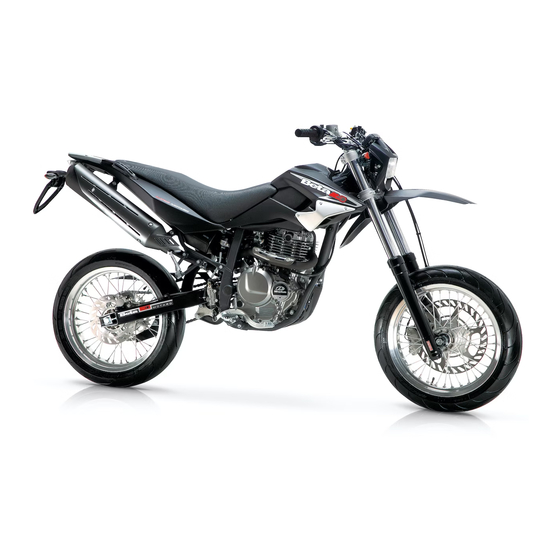
ALP 4.0 - MOTARD M4
Grazie per la fi ducia accordata e buon divertimento. Con questo
libretto abbiamo voluto darLe le informazioni necessarie per un
corretto uso e una buona manutenzione della Sua moto.
I dati e le caratteristiche indicate sul presente manuale non impegnano la
BETAMOTOR S.p.A che si riserva il diritto di apportare modifi che e miglio-
ramenti ai propri modelli in qualsiasi momento e senza preavviso.
I
1
Kapitel
Inhaltsverzeichnis

Verwandte Anleitungen für Beta ALP 4.0


Inhaltszusammenfassung für Beta ALP 4.0
- Seite 247 ALP 4.0 - MOTARD M4 Vielen Dank für Ihr Vertrauen und viel Spaß. Mit dieser Bedienungsanleitung möchten wir Ihnen die notwen- digen Informationen für einen richtigen Gebrauch und eine gute Wartung Ihres Motorrads geben. Alle Angaben zu Technik und Ausstattung sind unverbindlich. Die BETAMO- TOR S.p.A.
- Seite 248 HINWEIS Wir raten Ihnen nach der ersten bzw. zweiten Betriebsstunde mit Geländefahrt alle Sicherheits-Anzugsmomente zu überprüfen und dabei besonders auf folgende Bauteile zu achten: • Zahnkranz • Fußrastenbefestigung • Vorderer / Hinterer Bremssattel • Kotfl ügelbefestigung • Motor Bolzen • Stoßdämpfern Bolzen •...
- Seite 249 Hinweise zum Gebrauch des Fahrzeugs ..........251 Umweltfreundliches Fahren ..............251 Sicheres Fahren .................. 252 KAPITEL 1 ALLGEMEINE ANGABEN ..........253 Rahmen- und motornummer ..............254 Auslieferung ..................254 Zuladung ..................255 Reifen ....................255 Wichtigste Fahrzeugteile ..............257 Schlüssel und Schlösser ................ 258 Zünd-/ Lenkerschloß...
- Seite 250 Kontrollen nach der Fahrzeugpfl ege ............308 Wartungsprogramm ................309 Längeres Stilllegen des Fahrzeugs ............310 Nach längerem Stillegen des Fahrzeugs ..........310 KAPITEL 4 EINSTELLUNGEN ............311 Einstellung der bremsen ............... 312 Einstellung der Kupplung ..............312 Einstellung des hinteren Stoßdämpfers ............. 313 Leerlaufeinstellung ................
-
Seite 251: Hinweise Zum Gebrauch Des Fahrzeugs
HINWEISE ZUM GEBRAUCH DES FAHRZEUGS • Das Fahrzeug muß vorschriftsmäßig mit folgendem ausgestattet sein: Nummernschild, Fahrzeugschein, Fahrzeugsteuer- und Versicherungsmarke. • Das Fahren und der Transport mit Tieren und nicht fest am Fahrzeug befestigten oder am Fahrzeug überstehenden Gegenständen ist verboten. Die vom Hersteller angegebene Nutzlast darf nicht überschritten werden. -
Seite 252: Sicheres Fahren
SICHERES FAHREN • Die Straßenverkehrsordnung beachten. • Stets einen zugelassenen Sturzhelm tragen und diesen festschnallen. • Das Schutzvisier am Helm immer sauber halten. • Enganliegende Kleidung tragen. • Niemals mit spitzen oder zerbrechlichen Gegenständen in den Taschen fahren. • Die Rückspiegel richtig einstellen. •... -
Seite 253: Kapitel 1 Allgemeine Angaben
INHALTSVERZEICHNIS KAPITEL 1 ALLGEMEINE ANGABEN Rahmen- und motornummer Auslieferung Zuladung Reifen Wichtigste Fahrzeugteile Schlüssel und Schlösser Zünd-/ Lenkerschloß Helmschloß Armaturenbrett und Bedienungselemente Anzeigen am LCD Technische Angaben Elektrischer Schaltplan Elektrische Anlage Das AIS-Ventil... -
Seite 254: Rahmen- Und Motornummer
RAHMEN- UND MOTORNUMMER RAHMENNUMMER Die Rahmennummer A ist auf der rechten Seite des Lenkrohrs eingepräg. MOTORNUMMER Die Motornummer B befi ndet sich in dem in der Abbildung gezeigten Bereich. ACHTUNG: Eine Änderung an Rahmen- und Motor- nummern ist gesetzlich verboten und wird schwer bestraft. -
Seite 255: Zuladung
• Den Reifendruck so einstellen, daß er inner- Zu niedriger Reifendruck halb der angegebenen Druckwerte liegt. • Den Reifendruck alle 15 Tage überprü- fen. • Den Reifendruck nur an kalten Reifen überprüfen. Richtiger Reifendruck REIFEN ALP 4.0 REIFEN VORNE HINTEN Reifenmaße (90/90-21) (140/80-18) 70R oder (130/80-18) 66R... - Seite 256 Anmerkung: Das Reifenprofi l (Schlauchreifen - TUBE TYPE) muß mindestens 2 mm betragen. Fahren mit geringerem Reifenprofi l wird gesetzlich bestraft. • Vor jedem Fahrtantritt die Reifen auf Schnittstellen, Abschürfungen, Aufblähen usw. überprüfen. Werden Beschädigungen am Reifen festgestellt, muß der Reifen von einem Fachmann überprüft werden.
-
Seite 257: Wichtigste Fahrzeugteile
WICHTIGSTE FAHRZEUGTEILE ALP 4.0 MOTARD M4 Wichtigste Fahrzeugteile: 1 - Luftfi lter 8 - Rücklicht 16 - Motorschutz 2 - Benzintank 9 - Hintere Blinker 17 - Sitzbank 3 - Tankverschluß 10 - Seitenständer 18 - Motor 4 - Schalldämpfer 11 - Helmschloß... -
Seite 258: Schlüssel Und Schlösser
SCHLÜSSEL UND SCHLÖSSER Der Motorroller wird mit zwei Schlüsseln und den entsprechenden Ersatzschlüsseln ausgeliefert, die für das Zünd-/ Lenkschloß und das Helmschloß benutzt werden. ACHTUNG: Den Ersatzschlüssel nicht im Fahrzeug, sondern an einem sicheren und leicht zu- gänglichen Ort aufbewahren. Wir raten Ihnen die auf den Schlüsseln eingeprägte Kennziffer in die Bedienungsanleitung (oder woanders) einzutragen. -
Seite 259: Armaturenbrett Und Bedienungselemente
ARMATURENBRETT UND BEDIENUNGSELEMENTE 1 - LCD 10 - Startschalter 2 - Zündschloß 11 - Schalter zum Abstellen des Motors 3 - Leerlauf anzeigen 12 - Blinkerschalter 4 - Blinkerkontrolle 13 - Hupenschalter 5 - Fernlichtkontrolle 14 - Licht-Wechselschalter 6 - Seitenständerkontrolle 15 - Lichthupe 7 - Kupplungshebel 16 - Scroll... -
Seite 260: Anzeigen Am Lcd
ANZEIGEN AM LCD 1. INSTRUMENTENAUSRÜSTUNG Tachometer Batterie-Symbol TOTAL: Gesamt-Kilometerstand TD: Teilstrecken-Kilometerstand TIME: Uhr LAP: Chronometer Taste Mode Kippständer-Kontrolllampe Ist-Geschwindigkeit 10 Blinkerkontrolle 11 Fernlichtkontrolle 12 Leerlaufkontrolle... -
Seite 261: Funktion Ist-Geschwindigkeit
2. FUNKTIONS-MERKMALE 2.1 Funktion Ist-Geschwindigkeit Diese Information wird immer an den Ziffern 10 ÷ 12 (Abbildung 1 und Abbildung 2) angezeigt. Abbildung 1 Ist als Maßeinheit km/h (Voreinstellung) gewählt worden, wird das entsprechende Symbol angezeigt. Mit Druck auf die Taste und Öffnen des Setup-Menu kann die Maßeinheit geändert und auf mph eingestellt werden (Abbildung 2). -
Seite 262: Teil-Fahrtstrecke (Td)
Die Information wird immer in km berechnet. Die Anzeige kann aber in km (Voreinstellung- swert) oder in Meilen erfolgen. Das Umstellen der Maßeinheit erfolgt über das Setup-Menu. Bei einem normaler Einsatz der Instrumente kann diese Information nicht auf Null zurückge- stellt werden. - Seite 263 2.4 Chronometer (LAP) Diese Funktion beschreibt die Funktion/ Anzeige des Chronometers. Die Information wird an den Ziffern 1 ÷ 5 zusammen mit der Schrift LAP angezeigt. Um das Menu für das Chronometer zu öffnen, auf den Menupunkt (siehe Abbildung 6) ein- Abbildung 6 stellen und dann die Taste solange gedrückt halten, bis das Chronometer angezeigt wird...
-
Seite 264: Höchstgeschwindigkeit (Max)
Bei Geschwindigkeit >0 ist die Funktion LAP nicht zugänglich: Bei Druck auf die Taste wird die angezeigte Funktion geändert. Bei Geschwindigkeit >0 kann die Funktion LAP nicht beendet werden: Bei Druck auf die Taste wird der angezeigte Wert zurückgesetzt (wenn Druck-Dauer > 5 Sekunden). Der Wert wird nicht dauerhaft gespeichert. -
Seite 265: Batterieladezustand
2.6 Standby Die Standby-Funktion wird zum Einstellen der Uhr verwendet (siehe Absatz 2.8.1). Die Information wird wie in Abbildung 10 gezeigt angezeigt. Abbildung 10 2.7 Batterieladezustand Die Information wird durch die Grafi kbal- ken unten links angezeigt (siehe Abbildung 11). Abbildung 11 Der Grafi... -
Seite 266: Einstellen Der Uhr
2.8 Uhr Diese Funktion beschreibt die Funktion/ Anzeige der Funktion aktuelle Uhrzeit. Dies Funktion wird immer an den Ziffern 6 ÷ 9 im Format hh:mm angezeigt (Abbildung 12). Die Uhr bleibt auch dann eingeschaltet, wenn sich der Mikroprozessor auf Energiesparmo- dus (Sleep-Mode) stellt. -
Seite 267: Anmerkung
In diesem Fall erscheint an den Ziffern 10 und 11 während der Einstellung die Schrift AM oder an den Ziffern 11 und 12 die Schrift PM (siehe Abbildung 14). ANMERKUNG: Solange das Setup-Menu geöffnet ist, wird die Uhrzeit NICHT aktualisiert. ANMERKUNG: Nach dem Öffnen des Einstellungs-Menus: - Nach Ablauf von 20 Sek. -
Seite 268: Kontrolllampen Und Hintergrundbeleuchtung
4. KONTROLLLAMPEN UND HINTERGRUNDBELEUCHTUNG 4.1 Blinkerkontrolle Das System schaltet diese Kontrolllampe ein, sobald die Blinker eingeschaltet werden. ANMERKUNG: Das Signal muss bereits alternierend zur Instrumen- tenausrüstung gelangen. 4.2 Fernlichtkontrolle Das System schaltet diese Kontrolllampe ein, sobald das Fernlicht eingeschaltet wird. 4.3 Leerlaufkontrolle Das System schaltet diese Kontrolllampe ein, sobald der Schalthebel auf Leerlauf gestellt wird. -
Seite 269: Ändern Der Maßeinheit
5.1 Ändern der Maßeinheit Es werden nur die Symbole km/h und mph angezeigt. Die ausgewählte Maßeinheit blinkt (mit f=1Hz, Duty=50%) (Abbildung 16). Mit einem kurzen Druck auf die Taste wird die ausgewählte Einheit geändert, mit einem lan- Abbildung 16 gen Druck auf die Taste kann auf die nächste Einstellung umgestellt oder das Setup-Menu beendet werden. -
Seite 270: Start-Up (Starten Des Systems)
7. START-UP (STARTEN DES SYSTEMS) Beim Einschalten der Instrumente werden für den Anwender eine Reihe von Informationen angezeigt, die zur Vereinfachung an aufei- nander folgenden Seiten angezeigt werden: • 1. Seite (bei jedem Anschluss an die Fahrzeug-Batterie): Software-Version und Ausgabedatum (für ungefähr 3 Sekunden) Abbildung 17 (Abbildung 17). -
Seite 271: Technische Angaben
TECHNISCHE ANGABEN MAXIMAL ZULÄSSIGES GESAMTWICHT ........... 340 kg LEERGEWICHT ................133 kg FAHRZEUGMAßE - ALP 4.0 Gesamtlänge ................2208 mm Gesamtbreite ................850 mm Gesamthöhe vom Boden...............1240 mm Radstand ...................1444 mm Sitzbankhöhe ................863 mm Bodenabstand ................275 mm FAHRZEUGMAßE - MOTARD M4 Gesamtlänge ................2160 mm Gesamtbreite ................860 mm... - Seite 272 ................... 570 cc links ..................... 570 cc Öltyp ................Viskosität SAE 7,5 Ölstand .............. 180 mm vom oberen Rand Vorlauf ................101 mm (ALP 4.0) 58 mm (MOTARD M4) HINTERRADAUFHÄNGUNG Einzelstoßdämpfer mit einstellbarer Federvorspannung Stoßdämpferhub ..............83 mm (ALP 4.0) 100 mm (MOTARD M4) VORDERRADBREMSE - ALP 4.0...
- Seite 273 Ventile ................... 4 Stck. Nebenantrieb ..............15/48 (ALP 4.0) 15/42 (MOTARD M4) Ketten mit O-Ring ....REGINA DERVIO 5/8’ - Kettenteilung 112 (ALP 4.0) REGINA DERVIO 5/8’ - Kettenteilung 110 (MOTARD M4) Fett für Züge ..............BARDAHL MPG2 Ventilspiel ..............Einlass 0,05 - 0,10 mm Auslass 0,8 - 0,13 mm Starten ..................Elektrischer...
-
Seite 274: Elektrischer Schaltplan
ELEKTRISCHER SCHALTPLAN... -
Seite 275: Zeichenerklärung Elektrischer Schaltplan
ZEICHENERKLÄRUNG ELEKTRISCHER SCHALTPLAN VORDERER RECHTER BLINKER (BIRNE 12V - 10W) VORDERER BREMSLICHTSCHALTER RECHTE EINHEIT BEDIENUNGSELEMENTE SCHALTER ZUM ABSTELLEN DES MOTORS ANLASSERSCHALTER RADDREHZAHLSENSOR FERNLICHTKONTROLLE BLINKERKONTROLLE DISPLAY LEERLAUF-KONTROLLEUCHTE SEITENSTÄNDERKONTROLLE TASTENWAHL SCROLL HUPENSCHALTER LICHT-WECHSELSCHALTER LICHTHUPE BLINKERSCHALTER LINKE EINHEIT BEDIENUNGSELEMENTE KUPPLUNGSSCHALTER KONDENSATOR 4700 ?F - 25V ZÜNDSPULE VORDERER LINKER BLINKER (BIRNE 12V - 10W) GLEICHSTROMREGLER 12V... -
Seite 276: Elektrische Anlage
ELEKTRISCHE ANLAGE Zum Austausch der Batterie die Befestigungsschraube an der Sitzbank um 1/4 Umdrehung gegen den Uhrzeigersinn drehen und dann die Sitzbank nach hinten verschieben. ACHTUNG: Um Schäden an der elektrischen Anlage zu vermeiden, niemals die Kabel bei lau- fendem Motor abnehmen. RELAIS SEITENSTÄNDER A SICHERUNG B - 2 STCK. -
Seite 277: Zündspule - Anlassermotor I
HINWEISE ZUR BATTERIE G Die Batterie in das entsprechende Fach unter der Sitzbank einsetzen (Position wie im Foto) und mit dem mitgelieferten Gummiriemen H befestigen. Das schwarze Kabel am Minuspol (-) und das rote Kabel am Pluspol (+) zusammen mit der roten Schutzkappe anbringen. Die Sitzbank wieder anbringen. -
Seite 278: Vorrichtungen Für Version E3
VORRICHTUNGEN FÜR VERSION E3 Die neuesten Modelle haben eine E3 Zulassung, sie unterscheiden sich von den vorherigen Zulassungen durch: DAS AIS-VENTIL Es wird AIS A genannt, und ist ein System zur Luftzuleitung, das eine vollständige Verbrennung der unverbrannten Kohlen- wasserstoffe, die sich als Rückstand beim thermodynamischen Zyklus gebildet ha- ben, ermöglicht. -
Seite 279: Kapitel 2 Bedienungsvorschriften
INHALTSVERZEICHNIS KAPITEL 2 BEDIENUNGSVORSCHRIFTEN Kontrollen und Wartung vor und nach Einsatz im Gelände Empfohlene Schmiermittel Einfahren Starten des Motors Abstellen des Motors Tanken... -
Seite 280: Kontrollen Und Wartung Vor Und Nach Einsatz Im Gelände
KONTROLLEN UND WARTUNG VOR UND NACH EINSATZ IM GELÄNDE Um unangenehme Störungen während der Fahrt mit dem Fahrzeug zu vermeiden, sollte das Fahrzeug vor und nach jedem Einsatz kontrolliert und gewartet werden. Die kurze Zeit, die sie für diese Arbeiten aufbringen, wird Ihnen helfen Geld und Zeit zu sparen. -
Seite 281: Einfahren
EINFAHREN Die Einfahrzeit dauert ungefähr 10 Be- triebsstunden, während dieser Zeit müs- sen folgenden Vorschriften eingehalten werden: • Den Motor vorm Losfahren warmlaufen lassen; • Fahrten mit gleichbleibender Geschwin- digkeit vermeiden. Bei Geschwindigkeits- änderungen spielen sich die mechani- schen Bauteile schneller und gleichmäßi- ger ein. -
Seite 282: Starten Des Motors
STARTEN DES MOTORS • Den Zündschlüssel im Zündschloß in Uhrzeigersinn drehen und sicherstellen, dass die Leerlaufkontrolle (N) am Arma- turenbrett aufl euchtet. HINWEIS: Nicht vergessen den Licht-Wechselschalter vorm Betätigen des Schlüssels auf Ab- blendlicht zu stellen (siehe Seite 259), so dass der Batterieverbrauch so gering wie möglich ist. -
Seite 283: Abstellen Des Motors
Anmerkung: Der Motor kann auch mit abgeklapptem Seitenständer gestartet werden, allerdings muß dabei der Leerlauf (N) eingelegt sein. Anmerkung: Im Notfall funktioniert dieses Fahrzeug auch ohne Batterie. ABSTELLEN DES MOTORS • Im Stand und im Leerlauf den Zündschlüs- sel auf “OFF” drehen. •... -
Seite 284: Tanken
TANKEN • Den Motor abstellen. • Den Tankdeckel A öffnen. Anmerkung: Der Tankinhalt beträgt ungefähr 10,5 Liter, davon sind 3 Liter Reserve. ACHTUNG: Eventuell auf die Karosserie oder andere Fahrzeugteile getropftes Benzin muss sofort abgetrocknet werden. Vorm Tanken den Motor abstellen. Benzin ist äußert leicht entzündbar. -
Seite 285: Kapitel 3 Wartung Und Kontrollen
INHALTSVERZEICHNIS KAPITEL 3 WARTUNG UND KONTROLLEN Kontrolle motorölstand Wechsel von motoröl und Ölfi lter Leitung Öldampfsammlung Bremsfl üssigkeit, entlüften der bremsen Gabelöl Luftfi lter Zündkerze Vorderradbremse Hinterradbremse Vergaser Batterie Ausbau der plastikteile für ALP Ausbau der plastikteile für MOTARD M4 Hinweise für Geländefahrten Wechseln der endantriebseinheit Fahrzeugpfl... -
Seite 286: Kontrolle Motorölstand
KONTROLLE MOTORÖLSTAND Livello dell’olio del motore Bei diesem Fahrzeug muss die Kontrolle des Motorölstands bei warmem Motor vorgenommen werden, weil sich der Öl- tank oberhalb des Motors befi ndet (siehe Abbildung). Fig. A Fig. B Vorgehensweise zur Ölkontrolle • Prüfen, ob Öl im Motorblock ist. Dazu die Ölstand-Kontrollschraube A am Motor- block lösen und prüfen, ob Öl austritt. - Seite 287 Kontrolle Motorölstand Nur vornehmen, wenn zuvor das Vorhan- densein von Öl im Motor geprüft wurde (siehe Seite 286). • Den Motor starten und drei Minuten im Leerlauf laufen lassen. • Den Motor abstellen und eine Minute warten. • Den Deckel vom Öl-Einfüllstutzen abneh- men.
-
Seite 288: Wechsel Von Motoröl Und Ölfi Lter
WECHSEL VON MOTORÖL UND ÖLFILTER Das Motoröl muß bei warmem Motor gewechselt werden. Beim Ölwechsel den Motor nicht berühren, Verbrennungsge- fahr. • Der Ölfi lter muß beim Ölwechsel eben- falls ausgetauscht werden. • Das Motorrad auf den Ständer stellen. • Einen Behälter zum Auffangen des Altöls unter dem Motor aufstellen. - Seite 289 Das Öl aus dem Tank ablassen • Die 4 Befestigungsschrauben am hinteren Motorgehäuse entfernen. • Die Schraube Q abschrauben und das gesamte Öl aus dem Tank ausfl ießen lassen. • Beim ersten Ölwechsel (siehe Seite 281) sollte auch der Metallfi lter am Endteil des Tanks gereinigt werden.
- Seite 290 • Für ein vollständiges Ablassen des Öls auch aus dem Tank, die Sitzbank , die vorderen Seitenteile und den Tank ab- montieren. • Das Motorrad auf die linke Seite neigen und die Schraube H am Rahmen ab- schrauben. • Einen Gummischlauch I anbringen. •...
- Seite 291 Einbau • Beim Einbau in umgekehrter Reihenfolge wie beim Ausbau des Metall-Netzfi lters am Öltank vorgehen. • Einen neuen Ölfi lter einsetzen. • Die Feder und den O-Ring anbringen und den Filterdeckel mit den drei Muttern befestigen. • Die Feder und den O-Ring anbringen, den Ölfi...
-
Seite 292: Leitung Öldampfsammlung
LEITUNG ÖLDAMPFSAMMLUNG Die Leitung der Öldampfsammlung A befi ndet sich auf der linken Fahrzeugseite in der Nähe des Stoßdämpfers, kommt Unterseite des Filtergehäuses und sammelt die Motoröldämpfe. Sobald sich Öl in dieser Leitung befi ndet, muß diese geleert werden. Dazu den Verschluß am unteren Ende der Leitung abnehmen und das aus- fl... - Seite 293 Hinterradbremse Den Bremsflüssigkeitsstand am Brems- flüssigkeitsbehälter E überprüfen. Der Bremsfl üssigkeitsstand darf nie unter die Markierung des Mindeststands am Brems- fl üssigkeitsbehälter F abfallen. Gegebe- nenfalls den Bremsfl üssigkeitsstand wie folgt auffüllen: • Mit einem geeigneten Schlussel die Befestigungsschraube des Bremsfl ussig- keitsbehalters abschrauben G.
- Seite 294 Entlüften der Vorderradbremse Zum Entlüften der Vorderradbremse wie folgt vorgehen: • Die Gummikappe A vom Entlüftungsventil B abnehmen. • Den Deckel vom Bremsfl üssigkeitsbehälter abnehmen. • Einen Schlauch auf das Entlüftungsventil MOTARD B aufsetzen, das andere Schlauchende in einen Behälter leiten. •...
- Seite 295 Entlüften der Hinterradbremse Zum Entlüften der Hinterradbremse wie folgt vorgehen: • Die Gummikappe C. • Den Deckel vom Bremsfl üssigkeitsbehälter abnehmen. • Einen Schlauch auf das Entlüftungsventil D aufsetzen, das andere Schlauchende in einen Behälter leiten. • Das Ventil D (bei gezogenem Bremshe- bel) losschrauben und mit dem Bremshe- bel solange pumpen, bis nur noch Bremsfl...
-
Seite 296: Gabelöl
GABELÖL Rechter/Linker Gabelschaft Die Beschreibung zum Wechseln des Gabelöl hat rein informativen Charakter. Wir empfehlen Ihnen sich zum Austausch des Gabelöl an den BETAMOTOR-Kunden- dienst zu wenden. Zum Austausch des Gabelöls wie folgt vorgehen: 1) Die vier Befestigungsschrauben C der beiden Bügelschrauben D abschrau- ben und den Lenker entfernen. -
Seite 297: Luftfi Lter
LUFTFILTER Um an den Luftfi lter gelangen zu können, wie folgt vorgehen: • Das hintere linke Seitenteil A wie in der Abbildung gezeigt leicht anheben. • Die 3 Befestigungsschrauben B ab- schrauben und die Plastikverkleidung E abmontieren. • Die Befestigungsschraube D des Filter- deckels abschrauben und den Filter C ausbauen. -
Seite 298: Zündkerze
ZÜNDKERZE Eine gut gepfl egte Zündkerze senkt den Benzinverbrauch und sorgt für einen opti- malen Betrieb des Motors. Die Zündkerze sollte möglichst bei war- mem (und natürlich abgestelltem) Motor ausgewechselt werden, da die Schlak- keablagerungen und die Verfärbung des Isolationsteils wichtige Hinweise auf die Verbrennung, Schmierung und den allge- meinen Motorzustand geben. -
Seite 299: Vorderradbremse
VORDERRADBREMSE Kontrolle Um den Verschleißzustand der Vorderrad- bremse zu überprüfen, reicht es aus den Bremssattel von der Vorderseite her zu betrachten. Von dort aus sieht man die beiden Bremsbeläge, die eine Belagstärke von mindestens 2 mm haben müssen. Bei geringerer Belagstärke müssen die Brem- sbeläge sofort ausgewechselt werden. -
Seite 300: Vergaser
VERGASER Damit der Vergaser jederzeit bestens funktioniert, muß er gründlich gereinigt werden. Den Vergaser aus dem Fahrzeug ausbau- Die zwei Schrauben A entfernen und die Vergaserwanne ausbauen. Die rich- tige Schwimmerposition überprüfen. Das Schwimmerblech muß, wie in der Abbil- dung gezeigt, parallel zum Vergaserge- häuse stehen. -
Seite 301: Ausbau Der Plastikteile Für Alp
AUSBAU DER PLASTIKTEILE FÜR ALP Um Kontrollen oder andere Arbeiten an einigen Fahrzeugbereichen leicht ausfüh- ren zu können, müssen Karosserie- und andere Fahrzeugteile ausgebaut werden. Ausbau der Sitzbank •Die Befestigung A um 90° gegen den Uhrzeigersinn drehen. Die Sitzbank in Richtung Fahrzeugheck herausziehen. - Seite 302 Ausbau der hinteren Seitenteile • Zuerst die hinteren Griffe abmontieren, dann die Befestigungsschraube N ab- schrauben und schließlich die Seitenteile herausziehen. Ausbau Benzintank •Die Befestigungsschraube I am Rahmen lösen, die Leitung vom Benzinhahn abnehmen und den Benzintank durch Ziehen nach hinten ausbauen. Anmerkung: Der Tank kann komplett mit den vorderen Seitenteilen ausgebaut werden.
-
Seite 303: Ausbau Der Plastikteile Für Motard M4
AUSBAU DER PLASTIKTEILE FÜR MO- TARD M4 Um Kontrollen oder andere Arbeiten an einigen Fahrzeugbereichen leicht ausfüh- ren zu können, müssen Karosserie- und andere Fahrzeugteile ausgebaut werden. Ausbau der Sitzbank •Die Befestigung A um 90° gegen den Uhrzeigersinn drehen. Die Sitzbank in Richtung Fahrzeugheck herausziehen. - Seite 304 Ausbau der hinteren Seitenteile •Nach dem Ausbau der vorderen Seiten- teile und der Griffe können die hinteren Plastikverkleidungen M abmontiert wer- den. Hierzu zuerst die beiden seitlichen Befestigungen N und dann die drei Schrauben O abschrauben. Die Seiten- teile aus den Steckverbindungen lösen und herausziehen.
-
Seite 305: Hinweise Für Geländefahrten
HINWEISE FÜR GELÄNDEFAHRTEN Für einen Einsatz des Fahrzeugs im Ge- lände können hinderliche Teile abgebaut werden, so z. B.: der Nummernschildhalter, der Ständer, der Blinker und die Beifahrer- Fußrasten. Ausbau Ständer • Die Befestigungsschraube C des Ständer- schalters abschrauben und den Schalter entfernen. -
Seite 306: Wechseln Der Endantriebseinheit
WECHSELN DER ENDANTRIEBSEINHEIT Muss eines der drei Elemente der Endan- triebseinheit (Ritzel, Kette und Zahnkranz) wegen Verschleiß gewechselt werden, sollte stets die gesamte Einheit gewechselt werden. Wechseln der Kette • Mit einem Flachkopfschraubenzieher wie in der Abbildung gezeigt vorgehen. • Das Kettenschloss such und auf den Zahnkranz einstellen, anschließend die Sperre B am Kettenschloss A entfernen. - Seite 307 Austausch des Kettenritzels • Das Hinterrad lockern. • Die Einstellvorrichtungen der Kette lok- kern. • Das Hinterrad bis zum Anschlag nach vorne verschieben, so dass sich die Kette lockert. • Die zwei Befestigungsschrauben F der Abdeckung abschrauben. • Den ersten Gang einlegen und den Seegerring G zur Befestigung des Ritzels entfernen.
-
Seite 308: Fahrzeugpfl Ege Und Kontrollen
FAHRZEUGPFLEGE UND KONTROLLEN Zum Aufweichen von Schmutz und Schlamm auf den lackierten Oberfl ächen einen Wasserstrahl benutzen. Ist der Schmutz aufgeweicht, muss er mit einem weichen Schwamm mit viel Wasser und Autoshampoo (2 - 4% Shampoo im Wasser) entfernt werden. Anschließend mit viel Wasser abspülen und mit einem Luftstrahl und einem Lappen oder Wildledertuch trocknen. -
Seite 309: Wartungsprogramm
WARTUNGSPROGRAMM HINWEIS: Wenden Sie sich für Arbeiten am Motorrad an das BETAMOTOR-Kundendienstnetz. -
Seite 310: Längeres Stilllegen Des Fahrzeugs
LÄNGERES STILLLEGEN DES FAHRZEUGS Soll der Motorroller längere Zeit stillgelegt werden, z. B. während des Winters, müssen zur richtigen Aufbewahrung einige einfache Vorkehrungen getroffen werden: • Das Fahrzeug und alle Fahrzeugteile gründlich reinigen. • Den Reifendruck um ungefähr 30% senken, die Räder möglichst vom Boden anhe- ben. -
Seite 311: Kapitel 4 Einstellungen
INHALTSVERZEICHNIS KAPITEL 4 EINSTELLUNGEN Einstellung der bremsen Einstellung der Kupplung Einstellung des hinteren Stoßdämpfers Leerlaufeinstellung Einstellung des Gaszuges Kontrolle und Einstellung Lenkerspiel Spannen der Kette Einstellung des Scheinwerfers... -
Seite 312: Einstellung Der Bremsen
EINSTELLUNG DER BREMSEN Vorderradbremse Die Vorderradbremse ist eine Scheiben- bremse mit hydraulischer Betätigung für die keinerlei Einstellungsarbeiten benötigt werden. Hinterradbremse Die Hinterradbremse ist eine Scheiben- bremse mit hydraulischer Betätigung, an der keine Einstellungen vorgenommen wer- den müssen. Die Stellung des Bremspedals kann über die Einstellvorrichtungen A und B eingestellt werden. -
Seite 313: Einstellung Des Hinteren Stoßdämpfers
Gewindering B und den Konter-Gewindering A festziehen. ACHTUNG: Für die Einstellung des hinteren Stoßdäm- pfers ALP 4.0 beachten, dass die Federlän- ge bei Standard-Vorspannung 194 mm be- trägt. Beim Fahrzeug MOTARD M4 beträgt die Federlänge am hinteren Stoßdämpfer bei Standard-Vorspannung 235 mm. -
Seite 314: Kontrolle Und Einstellung Lenkerspiel
KONTROLLE UND EINSTELLUNG LEN- KERSPIEL Das Spiel am Lenkrohr regelmäßig über- prüfen. Dazu das Vorderrad bremsen und das Fahrzeug wie in der Abbildung gezeigt nach vorne und hinten bewegen. Wird ein Spiel am Lenkrohr festgestellt, muß wie folgt vorgegangen werden: •... -
Seite 315: Spannen Der Kette
SPANNEN DER KETTE Damit die Antriebskette länger hält, muß die Kettenspannung in regelmäßigen Abständen überprüft werden. Die Kette stets sauber halten und sch- mieren. Hängt die Kette mehr als 20 mm durch, muß die Kette gespannt werden. • Die Muttern auf beiden Seiten der hinte- ren Schwinge lösen. -
Seite 316: Einstellung Des Scheinwerfers
EINSTELLUNG DES SCHEINWERFERS • Die Einstellung des Scheinwerfers erfolgt von Hand, nachdem die beiden Inbus- schrauben an den Scheinwerferseiten gelöst wurden. • Der Scheinwerfer muß in regelmäßigen Abständen eingestellt werden. Der Schein- werfer kann nur in der Höhe verstellt werden. •... -
Seite 317: Kapitel 5 Austauschen/ Auswechseln Von Teilen
INHALTSVERZEICHNIS KAPITEL 5 AUSTAUSCHEN/ AUSWECHSELN VON TEILEN Auswechseln der Bremsbeläge an der Vorderradbremse Auswechseln der Bremsbeläge an der Hinterradbremse Auswechseln lampen ALP Auswechseln Lampen MOTARD M4 Auswechseln von blinkern und Rücklicht Auswechseln der Nummernschildbeleuchtung Eigenschaften Lampe... -
Seite 318: Auswechseln Der Bremsbeläge An Der Vorderradbremse
Bremsbeläge hat rein informativen Cha- rakter. Wir empfehlen Ihnen sich zum Auswechseln der Bremsbeläge an den BETAMOTOR-Kundendienst zu wenden. VORDERRADBREMSE FÜR ALP 4.0 Zum Auswechseln der Bremsbeläge wie folgt vorgehen: • Die beiden Schrauben A abschrauben und den Bremssattel entfernen. -
Seite 319: Vorderradbremse Für Motard M4
VORDERRADBREMSE FÜR MOTARD M4 Zum Auswechseln der Bremsbeläge wie folgt vorgehen: • Die beiden Schrauben A abschrauben und den Bremssattel von der Spezialhal- terung C abmontieren. • Die zwei Befestigungsschrauben B ab- schrauben. • Die Bremsbeläge herausziehen. ACHTUNG: Bei Ausbau des Bremssattels der Vorderrad- bremse darauf achten, dass der Sensor C nicht beschädigt wird. -
Seite 320: Auswechseln Der Bremsbeläge An Der Hinterradbremse
AUSWECHSELN DER BREMSBELÄGE AN DER HINTERRADBREMSE Die Beschreibung zum Auswechseln der Bremsbeläge hat rein informativen Cha- rakter. Wir empfehlen Ihnen sich zum Auswechseln der Bremsbeläge an den BETAMOTOR-Kundendienst zu wenden. Zum Auswechseln der Bremsbeläge wie folgt vorgehen: • Das Fahrzeug auf den Hauptständer stellen, das Hinterrad muss vom Boden angehoben sein. -
Seite 321: Auswechseln Lampen Alp
AUSWECHSELN LAMPEN ALP VORNE Die Halterung und die Scheinwerfereinheit wie auf Seite 302 beschrieben ausbauen. Den Kabelstecker abziehen, die Gummi- haube A anheben, die Sicherungsfeder der Lampe aushaken und die durchge- brannte Lampe durch eine neue Lampe mit gleichen Eigenschaften auswechseln. Darauf achten, dass das Lampenglas nicht angefasst wird. -
Seite 322: Auswechseln Lampen Motard M4
AUSWECHSELN LAMPEN MOTARD VORDERER Zum Wechseln der Scheinwerferlampe die Kabelstecker A von der Lampe trennen und die Gummikappe B entfernen. Die Befestigungsflansch C gegen den Uhrzeigersinn drehen und die Lampe aus dem Parabolspiegel entfernen. Eine neue Lampe einsetzen (12V - 55/60W). -
Seite 323: Auswechseln Von Blinkern Und Rücklicht
AUSWECHSELN VON BLINKERN UND RÜCKLICHT Die Blinker und Rücklichter der beiden Modellversionen (ALP 4.0 und M4) sind mit LED ausgestattet. Bei einem Ausfall der Blinker muss der gesamte Blinker wie folgt gewechselt werden: VORDERE BLINKER Die zum ausgefallenen Blinker gehörende Mutter A an der Innenseite der Maske abschrauben. -
Seite 324: Auswechseln Der Nummernschildbeleuchtung
AUSWECHSELN DER NUMMERNSCHIL- DBELEUCHTUNG Zum Auswechseln der Lampe der Num- mernschildbeleuchtung reicht es aus die Schraube A abzuschrauben, das Glas abzunehmen und die defekte Lampe durch eine Lampe mit gleichen Eigenschaften zu ersetzen. Beim Einsetzen darauf achten, dass das Lampenglas nicht angefasst wird, um die Lampeneffi... -
Seite 325: Kapitel 6 Was Ist Im Notfall Zu Tun
INHALTSVERZEICHNIS KAPITEL 6 WAS IST IM NOTFALL ZU TUN ALPHABETISCHES INHALTSVERZEICHNIS... - Seite 326 STÖRUNG URSACHE ABHILFE - Benzinversorgung verstopft Die Benzinanlage reinigen Der Motor springt nicht (Leitungen, Benzintank, Benzin- hahn) - Luftfi lter stark verschmutzt Wie auf Seite 297 beschrieben vorgehen - Kein Strom an der Zündkerze Zündkerze reinigen oder austauschen. Bleibt das Problem bestehen, wenden Sie sich bitte an den Kundendienst - Motor abgesoffen Bei voll geöffnetem Gasgriff einige...
- Seite 327 Abstellen des Motors ................283 Anzeigen am LCD ................260 Armaturenbrett und Bedienungselemente ..........259 Ausbau der plastikteile für ALP ............... 301 Ausbau der plastikteile für MOTARD M4 ..........303 Auslieferung ..................254 Auswechseln der Bremsbeläge an der Hinterradbremse ......320 Auswechseln der Bremsbeläge an der Vorderradbremse ......
- Seite 328 Längeres Stilllegen des Fahrzeugs ............310 Leerlaufeinstellung ................313 Leitung Öldampfsammlung ..............292 Luftfi lter ..................... 297 Nach längerem Stillegen des Fahrzeugs ..........310 Rahmen- und motornummer ..............254 Reifen ....................255 Schlüssel und Schlösser ................ 258 Sicheres Fahren .................. 252 Spannen der Kette ................