Herunterladen Inhalt Inhalt Diese Seite drucken
Inhaltsverzeichnis

Werbung

Verfügbare Sprachen
  • DE

Verfügbare Sprachen

  • DEUTSCH, seite 26

Werbung

Inhaltsverzeichnis
loading

Inhaltszusammenfassung für Fluke PRUFTECHNIK PULLALIGN

  • Seite 2 Perfect pulley alignment with laser Riemenscheiben perfekt ausrichten La solution parfaite pour vos alignements de poulies La soluzione perfetta per l’allineamento delle pulegge PULLALIGN ® La perfecta alineación de poleas mediante láser Perfect pulley alignment with laser Perfekcyjne osiowanie kół pasowych przy użyciu lasera Dear Customer, At PRÜFTECHNIK we strive to produce...
  • Seite 3: Inhaltsverzeichnis

    Contents Contents Foreword ..................3 PULLALIGN packages ..............4 ALI 2.002SET PULLALIGN in pouch ........... 4 ALI 2.003SET PULLALIGN Lite in pouch ..........5 ALI 2.004 SET PULLALIGN Lite 2 in pouch ........5 Safety notes ................6 Intended use ..................6 Signal words ..................6 EU declaration of conformity .............
  • Seite 4: Foreword

    PRÜFTECHNIK Ismaning, Germany © Fluke Reliability; all rights reserved Both this manual and the product it describes are copyrighted. All rights belong to the publisher. The manual may not be copied, reproduced, translated or made accessible to a third party in any form, neither in its entirety nor as an excerpt.
  • Seite 5: Pullalign Packages

    PULLALIGN package PULLALIGN packages ALI 2.002SET PULLALIGN in pouch PULLALIGN ALI 2.002SET constitutes the listed items. ALI 2.100 PULLALIGN laser unit (red laser) ALI 2.801 (4 no.) Batteries (AAA) ALI 2.300 PULLALIGN reflector unit ALI 2.805 Pouch DOC 02.201 PULLALIGN safety info sheet ALI 2.300 PULLALIGN reflector unit...
  • Seite 6: Ali 2.003Set Pullalign Lite In Pouch

    PULLALIGN package ALI 2.003SET PULLALIGN Lite in pouch PULLALIGN Lite in a pouch ALI 2.003SET constitutes the listed items: ALI 2.100 PULLALIGN laser unit (red laser) ALI 2.801 (4 no.) Batteries (AAA) ALI 2.302 (3 no.) 3 magnetic targets ALI 2.805 Pouch DOC 02.201 PULLALIGN safety info sheet...
  • Seite 7: Safety Notes

    Safety notes Safety notes Intended use PULLALIGN is designed for use in industrial environments where pulley systems have to be aligned. Due to its simplicity, alignment using PULLALIGN requires only one operator. PRÜFTECHNIK assumes no liability for damage or injury resulting from uses other than those described in this document.
  • Seite 8: Magnetic Units

    Safety notes Warning Do not look directly into the laser beam at any time. (The natural blink reaction of the human eye is normally sufficient to protect the eyes from any dangers posed by looking at the laser beam briefly. But as natural blink reaction may fail to occur, care should be taken to avoid staring into the beam.) Do not insert any optical devices into the beam path.
  • Seite 9 Safety notes Warning Due to the powerful magnets on the PULLALIGN units, handle the units with care, and DO NOT transport the units without covering the magnets with the provided cover plate which is designed to lower the magnetic field strength significantly. When covering the magnets, slide the plate onto the surface of the magnets.
  • Seite 10: Component Labelling

    Labelling Component labelling The laser safety The laser safety warning label affixed warning label affixed to the rear side of the to the rear side of the PULLALIGN Lite 2 laser PULLALIGN laser unit unit ALI 2.131 ALI 2.100 The laser identification label affixed to the rear side of...
  • Seite 11: Getting Started

    Getting started Getting started Set-up PULLALIGN Open the PULLALIGN pouch and remove the compact and durable units that compose the alignment system. Warning Ensure machines to be aligned are isolated from mains supply. Before mounting the PULLALIGN units or the magnetic targets, remove the cover plate by sliding the plate.
  • Seite 12: If Using Magnetic Targets

    Getting started If using magnetic targets Attach the three magnetic targets on the machine to be moved. The targets are typically mounted 120° apart. Magnetic target ALI 2.302 or ALI 2.303 each set comprises 3 targets Check alignment condition Switch the laser on using its rocker switch. Warning Do not look into the laser beam at any time.
  • Seite 13: Misalignment Conditions As They Appear On A Machine

    Getting started Misalignment conditions as they appear on a machine Vertical angularity Offset Horizontal angularity Misalignment conditions as observed on the PULLALIGN units Vertical angularity Offset Horizontal angularity Angular and offset The images above depict the condition observed The image above depicts the condition when using the PULLALIGN reflector ALI 2.300.
  • Seite 14: Correcting Misalignment (Using Laser And Reflector)

    Getting started Laser line Misalignment condition observed here is a combination of vertical angularity and offset (PULLALIGN reflector ALI 2.300) Reference line Notice Alignment where possible should be carried out in places protected from strong sunlight, or the immediate area should be shaded in order to allow easy viewing of the laser line on the units.
  • Seite 15: Correcting Misalignment (Using Laser And Targets)

    Getting started Good alignment is achieved when the transmitted laser line and the corresponding reflected laser line harmonizes with the reference lines on the reflector and laser transmitter respectively. Correcting misalignment (using laser and targets) 1. Correct angularity by shimming moveable machine using PERMABLOC or LAMIBLOC shims from PRÜFTECHNIK.
  • Seite 16: Power Requirements

    Getting started Power requirements PULLALIGN is powered with 4 "AAA" batteries. The operating time for ALI 2.100 (red laser) is approximately 25 hours, and for ALI 2.132 (green laser) is approximately 17 hours. To replace depleted batteries, use your thumb or a coin and lift off the end cap attached to the battery holder situated at the opposite end of the switch.
  • Seite 17: Pulley Alignment

    Pulley alignment Pulley alignment Importance of good alignment Good pulley alignment increases efficiency by reducing premature wear or failure of pulleys, belts and bearings. Pulleys can be aligned using the conventional string and straight-edge method but this often time consuming and prone to error. For the reflector version, PULLALIGN uses the tested, proven and well known reflected single beam principle, to significantly help reduce installation time, manpower and potential errors associ-...
  • Seite 18: Soft Foot

    Pulley alignment Notice Such problems must be corrected before proceeding with pulley alignment. Soft foot Inspect the moveable machine for 'soft foot'. Feeler gauges can be used under a loosened foot to measure the gap. Shim the machine foot with the largest amount of gap (the amount indicated with the feeler gauges) until no reading is larger than 0.05 mm (0.002"...
  • Seite 19: Pulley Run-Out

    Pulley alignment Pulley run-out The two types of run-out - rim (radial) and face (axial) - must both meet tolerance before final alignment corrections can be performed. The tolerance for radial or rim run-out on high speed pulleys (1500 R.P .M. and higher) should not exceed 0.12 mm (5 mils) total indicator reading (T.I.R.) on average, and may be increased up to 0.24 mm (10 mils) on slower pulleys.
  • Seite 20: Alignment

    Pulley alignment Alignment There are three basic parameters that describe pulley misalign- ment. These include vertical angularity, horizontal angularity, and axial offset and may occur in any combination. There are several pulley alignment methods. The most common is the straightedge and string method in which the strings must touch each pulley at two diametrically opposite positions simultaneously.
  • Seite 21 Pulley alignment Reflector unit Laser unit The diagrams below depict the misalignment conditions and the corresponding corrections as observed on the units. (Valid for only ALI 2.002SET.) Observed vertical angularity Observed offset Observed horizontal angularity after vertical after horizontal after offset angle correction angle correction correction...
  • Seite 22 Pulley alignment Since performing one alignment correction almost invariably affects the other alignment conditions, this process may have to be repeated several times. Notice The sequence in which the misalignment correction is carried out may vary from one situation to the next. PULLALIGN enables one to monitor all three alignment conditions simultaneously.
  • Seite 23: Pulley Alignment Tolerance

    Pulley alignment Warning Before running the machines make sure machine areas are clear, all equipment has been removed and all guards are back in place. The machines are now ready to be run. The final step is to run the machines for a couple of hours allowing the belts to stretch and seat themselves properly in the grooves.
  • Seite 24: Pullalign Technical Data

    Technical data PULLALIGN technical data Laser units ALI 2.100 (red laser) and ALI 2.131 (green laser) Type Semiconductor laser diode Beam power < 1.0 mW (according to IEC 60825-1:2014 condition 3) Beam divergence < 1.0 mrad Beam spread 70 deg. Maximum beam power <...
  • Seite 25 Contents subject to change without further notice, particularly in the interest of further techni- cal development. Reproduction, in any form whatsoever, only upon express written consent of PRÜFTECHNIK. © Copyright 2018 by Fluke Corporation Productive maintenance technology...
  • Seite 26 PULLALIGN ® Riemenscheiben perfekt ausrichten Bedienungsanleitung Verehrter Kunde, für Ihr Vertrauen bedanken wir uns ganz herzlich und hoffen, dass Sie mit unserem Produkt zufrieden sind. Sollten Sie - zu diesem Produkt oder zu dieser Anleitung - Verbesserungsvorschläge oder Anregungen haben, schreiben Sie uns bitte.
  • Seite 27 Inhalt Inhaltsverzeichnis Vorwort ..................3 PULLALIGN Pakete ..............4 ALI 2.002SET PULLALIGN mit Tasche ..........4 ALI 2.003SET PULLALIGN Lite mit Tasche ......... 5 ALI 2.004 SET PULLALIGN Lite 2 mit Tasche ........5 Sicherheitshinweise ..............6 Bestimmungsgemäße Verwendung ............ 6 Verwendete Signalwörter ..............6 EG-Konformität und EMV ..............
  • Seite 28: Vorwort

    Vorwort Vorwort Willkommen zum Ausrichten von Riemenscheiben mit PULLALIGN. Mit diesem leicht zu bedienenden Gerät von PRÜFTECHNIK werden Sie Ihre Ausrichtaufgaben mit Vergnügen verrichten. Ein gutes Ausrichten Ihrer Riemenscheiben reduziert die Kräfte auf Riemen und Riemenscheiben, die Schwingungen der Anlage und verbessert somit die Antriebseigenschaften Ihrer Maschine.
  • Seite 29: Pullalign Pakete

    PULLALIGN Paket PULLALIGN Pakete ALI 2.002SET PULLALIGN mit Tasche PULLALIGN, ALI 2.002SET, beinhaltet folgende Teile: ALI 2.100 PULLALIGN Lasereinheit (roter Laser) ALI 2.801 (4 St.) Batterien (AAA) ALI 2.300 PULLALIGN Reflektoreinheit ALI 2.805 Tasche DOC 02.201 PULLALIGN Sicherheits- und allgemeine Hinweise ALI 2.300 PULLALIGN Reflektoreinheit...
  • Seite 30: Ali 2.003Set Pullalign Lite Mit Tasche

    PULLALIGN Paket ALI 2.003SET PULLALIGN Lite mit Tasche PULLALIGN Lite mit Tasche ALI 2.003SET beinhaltet folgende Teile: ALI 2.100 PULLALIGN Lasereinheit (roter Laser) ALI 2.801 (4 St.) Batterien (AAA) ALI 2.302 (3 St.) 3 Zielträger ALI 2.805 Tasche DOC 02.201 PULLALIGN Sicherheits- und allgemeine Hinweise ALI 2.302 Zielträger...
  • Seite 31: Sicherheitshinweise

    Sicherheitshinweise Sicherheitshinweise Bestimmungsgemäße Verwendung PULLALIGN ist zum Ausrichten von Riemenscheiben im industriellen Bereich zu verwenden. Aufgrund der einfachen Handhabung des Gerätes kann die Ausrichtung durch eine Person durchgeführt werden. Für Schäden oder Verletzungen, die durch eine von diesem Handbuch abweichende Verwendung entstehen, übernimmt PRÜFTECHNIK keine Haftung.
  • Seite 32: Lasersicherheit

    Sicherheitshinweise Lasersicherheit In PULLALIGN ist der PULLALIGN laser ALI 2.100 (roter Laser) oder der PULLALIGN Lite 2 laser ALI 2.131 (grüner Laser) verbaut. Beide Laser haben die Laser-Klasse 2 gemäß IEC 60825- 1:2014. Beide Laser erfüllen die FDA-Spezifikationen 21 CFR 1040.10 und 1040.11, außer bei den Abweichungen gemäß...
  • Seite 33: Magnetische Einheiten

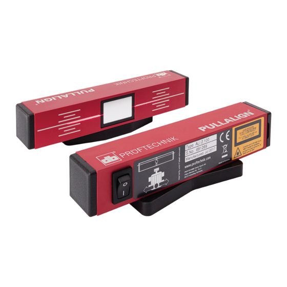
    Magnetische Einheiten Magnetische Einheiten Wippschalter (Ein/Aus) Referenzlinie Spiegel Magnet Magnet Laser Reflektoreinheit Lasereinheit ALI 2.100 ALI 2.300 oder ALI 2.131 Vorsicht Die Feldstärke der Magnete darf bestimmte Grenzen nicht überschreiten, um den problemlosen Transport von magne- tischem Material per Flugzeug zu ermöglichen. Aufgrund der starken Magnete, die an den PULLALIGN Einheiten angebracht sind, wird empfohlen, die Geräte mit Vorsicht zu behandeln.
  • Seite 34 Magnetische Einheiten Hinweis Lagern Sie die magnetischen PULLALIGN Einheiten bei Nichtgebrauch bitte ausschließlich im stabilen PULLALIGN Koffer (oder Tasche). Um die best mögliche Leistung zu erzielen, halten Sie die Optik der Lasereinheit, die reflektierende Oberfläche des Reflektors und das äußere Gehäuse beider Einheiten sauber und staubfrei.
  • Seite 35: Beschriftung

    Beschriftung Beschriftung der Komponenten Der Aufkleber Der Aufkleber mit der Laser mit der Laser Sicherheitswarnung Sicherheitswarnung ist auf der Rückseite ist auf der Rückseite der PULLALIGN der PULLALIGN Lite 2 Lasereinheit ALI 2.100 Lasereinheit ALI 2.131 angebracht angebracht Der Aufkleber mit der Laser- Identifkation ist auf der...
  • Seite 36: Erste Schritte

    Erste Schritte Erste Schritte PULLALIGN einrichten Öffnen Sie den PULLALIGN Tasche und entnehmen Sie daraus die kompakten und widerstandsfähigen Einheiten, aus denen das Ausrichtsystem besteht. Vorsicht Stellen Sie sicher, dass die auszurichtenden Maschinen von der Stromversorgung getrennt und gegen Wiedereinschalten während des Ausrichtens gesichert sind.
  • Seite 37: Bei Verwendung Magnetischer Zielträger

    Erste Schritte Bei Verwendung magnetischer Zielträger Montieren Sie die drei Zielträger auf die zu bewegende Maschine. Die Zielträger werden typischerweiser 120° versetzt befestigt. Zielträger ALI 2.302 oder ALI 2.303 jedes Set enthält 3 Zielträger...
  • Seite 38: Ausrichtzustand Überprüfen

    Erste Schritte Ausrichtzustand überprüfen Schalten Sie die Lasereinheit über den Wippschalter ein. Vorsicht Nicht in den Laserstrahl blicken. Die Fehlausrichtungen, die überprüft werden, sind der vertikale Winkelversatz, der horizontal Winkelversatz und der Parallelversatz. Die Position der übertragenen Laserlinie auf dem Reflektor gibt den vertikalen Winkelversatz und den Parallelversatz an.
  • Seite 39: Fehlausrichtungen, Wie Sie Durch Die Pullalign Einheiten Dargestellt Werden

    Erste Schritte Fehlausrichtungen, wie sie durch die PULLALIGN Einheiten dargestellt werden Vertikaler Parallelversatz Horizontaler Winkel und Versatz Winkelversatz Winkelversatz Die obigen Bilder zeigen den beobachteten Das obige Bild zeigt den beobachteten Zustand bei der Verwendung des PULLALIGN Zustand bei der Verwendung der Reflektors ALI 2.300.
  • Seite 40: Fehlausrichtungen Korrigieren (Mit Lasereinheit Und Reflektoreinheit)

    Erste Schritte Hinweis Das Ausrichtverfahren sollte möglichst an Stellen durchge- führt werden, die vor starker Sonneneinstrahlung geschützt sind. Die unmittelbare Umgebung sollte abgeschirmt werden, damit sich die Laserlinie auf den Einheiten deutlich hervorhebt. Im Falle extremer Fehlausrichtungen kann die Laserlinie auf einem weißen Blatt Papier, das neben der Lasereinheit gehalten wird, abgebildet werden.
  • Seite 41: Fehlausrichtungen Korrigieren (Mit Lasereinheit Und Zielträger)

    Erste Schritte Fehlausrichtungen korrigieren (mit Lasereinheit und Zielträger) 1. Winkelkorrektur durch Unterfütterung der beweglichen Maschine mit PERMABLOC oder LAMIBLOC Passplatten von ® ® PRÜFTECHNIK. Die Korrektur dieses Winkelversatzes kann auf der Oberfläche der Zielträger beobachtet werden. 2. Versatz-Korrektur durch axiale Anpassung der beweglichen Maschine.
  • Seite 42: Energieversorgung

    Erste Schritte Energieversorgung PULLALIGN wird durch 4 "AAA" Batterien versorgt. Die Betriebsdauer für den ALI 2.100 (roter Laser) beträgt ca. 25 Stunden, und für den ALI 2.132 (grüner Laser) ca. 17 Stunden. Zum Austauschen entleerter Batterien, heben Sie die Verschlusskappe mit Ihrem Daumen ab. Diese befindet sich am gegenüberliegenden Ende des Schalters.
  • Seite 43: Ausrichtung Von Riemenscheiben

    Ausrichtung von Riemenscheiben Ausrichtung von Riemenscheiben Vorteile einer guten Ausrichtung Ausgerichtete Riemenscheiben verringern vorzeitigen Verschleiß und die Wahrscheinlichkeit eines Ausfalls der Riemenscheiben, Riemen und Lager, und steigern somit die Leistungsfähigkeit. Natürlich kann eine Ausrichtung der Riemenscheiben auch mittels der herkömmlichen Schnüre und Haarlineale erfolgen, jedoch sind diese Methoden oft zeitraubend und fehlerbehaftet.
  • Seite 44: Prüfung

    Ausrichtung der Riemenscheiben Prüfung Unterziehen Sie die Riemen, Riemenscheiben und Laufrillen einer visuellen Prüfung auf Fehler. Achten Sie dabei auf sichtbare und fühlbare Risse, angeschlagene Stellen und übermäßigen Verschleiß der Rillen. Riemen und Riemenscheibe sollten guten Kontakt haben. Defekte Teile sind umgehend zu ersetzen. Hinweis Bevor mit der Ausrichtung der Riemenscheiben begonnen werden kann, müssen derartige Probleme behoben werden.
  • Seite 45: Ausrichtung Der Riemenscheiben

    Ausrichtung der Riemenscheiben Neue Riemen sind sachgemäß an einer kühlen, trockenen Stelle zu lagern, und sollten direkt einstrahlendem Sonnenlicht oder Heizluftzügen nicht ausgesetzt sein. Sie dürfen nicht an einzelnen Haken aufgehängt werden (Verformung). Riemenscheiben Achten Sie bei der Installation neuer Riemenscheiben und Riemen darauf, dass Sie die richtige Kombination von Riemen und Riemenscheibe sowie die richtige Riemengröße verwenden.
  • Seite 46: Ausrichtung

    Ausrichtung der Riemenscheiben Legen Sie die neuen Riemen in die Laufrillen der Riemenscheiben, positionieren Sie die Scheiben erneut so, dass sie ungefähr ausgerichtet sind, und kontrollieren Sie den Sitz der Riemen in den Laufrillen. Ausrichtung Die Fehlausrichtung von Riemenscheiben kann durch drei Messgrößen beschrieben werden.
  • Seite 47 Ausrichtung der Riemenscheiben PULLALIGN, auf der anderen Seite, lässt sich problemlos über die Magnetvorrichtungen an Riemenscheiben fast aller Größen schnell befestigen. Die Lasereinheit projiziert eine Laserlinie auf den Reflektor, der auf der gegenüberliegenden Scheibe montiert ist. Bei der Ausrichtung werden die Scheiben so versetzt, dass die übertragenen und reflektieren Laserlinien mit den entsprechen- den Referenzlinien übereinstimmen.
  • Seite 48 Ausrichtung der Riemenscheiben Das nachfolgende Diagram zeigt die Ausrichtzustände und die entsprechenden Korrekturen, die auf den Einheiten zu beobach- ten sind. (Gültig nur für ALI 2.002SET) Beobachteter vertikaler Beobachteter Winkelversatz horizontaler Beobachteter Winkelversatz Parallelversatz Nach der vertikalen Nach der horizontalen Nach der Parallelversatz Winkelkorrektur Winkelkorrektur...
  • Seite 49 Ausrichtung der Riemenscheiben Hinweis Die Reihenfolge, in der die Fehlausrichtungen korrigiert werden, kann sich von Fall zu Fall unterscheiden. PULLALIGN ermöglicht es Ihnen, alle drei Ausrichtzustände gleichzeitig zu kontrollieren. Die Genauigkeit der Ausrichtung wird dadurch erheblich verbessert und der Prozess lässt sich schneller und einfacher durchführen.
  • Seite 50 Ausrichtung der Riemenscheiben Vorsicht Bevor Sie die Maschinen anlaufen lassen, sorgen Sie dafür, dass die Maschinenbereiche aufgeräumt sind, alle Hilfsmittel entfernt wurden und die Sicherheitseinrichtungen wieder angebracht wurden. Die Maschinen sind nun betriebsbereit. Als letzter Schritt lassen Sie die Maschine einige Stunden laufen, damit die Riemen sich dehnen und einen guten Sitz in den Laufrillen finden können.
  • Seite 51: Ausrichttoleranzen Für Riemenscheiben

    Ausrichtung der Riemenscheiben Ausrichttoleranzen für Riemenscheiben Die normale Toleranz für Riemenantriebe liegt bei 0,5°. Die meisten Riemen- und Riemenscheibenhersteller geben diesen Wert vor. Bessere Toleranzen können jedoch erzielt werden, wenn das Ausrichtverfahren genauestens befolgt wird. In der hier wiedergegebene Tabelle werden die Toleranzen von Grad zu Versatz in mm pro 100 mm konvertiert.
  • Seite 52: Pullalign Technische Daten

    Technische Daten PULLALIGN Technische Daten Lasereinheiten ALI 2.100 (roter Laser) und ALI 2.131 (grüner Laser) Halbleiterlaser Leistung < 1,0 mW (gemäß IEC 60825-1:2014 Ausgabe 3.0) Strahldivergenz < 1,0 mrad Strahlöffnungswinkel 70 deg. Maximalleistung < 3,0 mW ALI 2.100 — 630 – 680 nm (rot, sichtbar) Wellenlänge ALI 2.131 —...
  • Seite 53: Für Messbare Erfolge In Der Instandhaltung

    Warenzeichen der ® ® PRÜFTECHNIK AG. Irrtümer und Kon struktions änderungen, insbe- sondere im Sinne technischer Weiter entwicklungen vorbehalten. Nachdruck, auch auszugsweise, nur mit schriftlicher Genehmigung der PRÜFTECHNIK AG. © Copyright 2018 by Fluke Reliability Für messbare Erfolge in der Instandhaltung...
  • Seite 54 PULLALIGN ® La solution parfaite pour vos alignements de poulies Cher client, Chez PRÜFTECHNIK Condition Monito- ring, nous tâchons de réaliser des produits et une documentation de haute qualité. Si vous avez des commentaires ou des sug- gestions sur ce document ou sur d'autres, votre retour est le bienvenue.
  • Seite 55 Contenu Contenu Avant - propos ................3 Ensembles PULLALIGN ...............4 ALI 2.002SET PULLALIGN avec étui ..........4 ALI 2.003SET PULLALIGN Lite avec étui ........... 5 ALI 2.004 SET PULLALIGN Lite 2 avec étui ........5 Notes de sécurité .................6 Signalétique d'avertissement .............. 6 Conformité...
  • Seite 56: Avant - Propos

    Avant - propos Avant - propos Bienvenue à l’alignement poulies utilisant PULLALIGN. Cet outil PRÜFTECHNIK, facile d’utilisation permettra à l’utilisateur d’accomplir les tâches d’alignement de poulies avec plaisir. Un système de poulies correctement aligné réduit l’usure et la vibration des machines et augmente la performance de celles-ci.
  • Seite 57: Ensembles Pullalign

    Ensemble PULLALIGN Ensembles PULLALIGN ALI 2.002SET PULLALIGN avec étui L'ensemble PULLALIGN ALI 2.002SET est constitué des éléments répertoriés ci-dessous. ALI 2.100 PULLALIGN Unité laser (laser rouge) ALI 2.801 (4 no.) 4 piles (AAA) ALI 2.300 PULLALIGN Unité réflecteur ALI 2.805 Étui DOC 02.201 PULLALIGN informations générales...
  • Seite 58: Ali 2.003Set Pullalign Lite Avec Étui

    Ensemble PULLALIGN ALI 2.003SET PULLALIGN Lite avec étui L'ensemble PULLALIGN Lite avec étui ALI 2.003SET est constitué des éléments répertoriés ci-dessous. ALI 2.100 PULLALIGN Unité laser (laser rouge) ALI 2.801 (4 no.) 4 piles (AAA) ALI 2.302 (3 no.) 3 cibles magnétiques ALI 2.805 Étui DOC 02.201...
  • Seite 59: Notes De Sécurité

    Notes de sécurité Notes de sécurité Le PULLALIGN est conçu pour l’utilisation en environnements industriels. En raison de sa simplicité, l’alignement avec PULLALIGN peut être fait par un seul opérateur. PRÜFTECHNIK n’assume aucune responsabilité pour des dommages résultant de l’utilisation de cet appareil à d’autres fins que celles décrites dans ce document.
  • Seite 60: Sécurité Du Laser

    Notes de sécurité Sécurité du laser Le système PULLALIGN utilise soit le laser PULLALIGN ALI 2.100 (laser rouge), soit le laser PULLALIGN Lite 2 ALI 2.131 (laser vert). Conformément à la norme CEI 60825-1:2014, les 2 lasers PULLALIGN ALI 2.100 et ALI 2.131 sont classifiés en tant que produit laser de classe 2.
  • Seite 61: Unités Magnétiques

    Unités magnétiques Unités magnétiques Commutateur Ligne de référence Emission du laser Aimant Aimant Surface réfléchissante Unité réflecteur Unité laser ALI 2.100 ALI 2.300 ou ALI 2.131 Avertissement En raison des aimants puissants du PULLALIGN, il est recom- mandé une manipulation avec soins. Ne pas transporter le PULLALIGN sans ses plaques de protection qui réduisent significativement le champ des aimants.
  • Seite 62 Unités magnétiques Recommandation Hors service, les unités magnétiques du PULLALIGN doivent être stockées dans leur coffret. Pour une performance maxi, assurez-vous que le système optique de l’émetteur laser, la surface réfléchissante du réflecteur, et le logement extérieur des deux unités soient maintenus propres sans poussières.
  • Seite 63: Étiquettes Des Composants

    Étiquettes Étiquettes des composants Étiquette d'avertis- Étiquette d'avertis- sement de sécurité sement de sécurité du laser apposée à du laser apposée à l'arrière de l'unité l'arrière de l'unité laser PULLALIGN laser PULLALIGN Lite 2 ALI 2.100 ALI 2.131 Etiquette avec référence du laser, numéro de série et date de fabrication...
  • Seite 64 Mode d'emploi résumé Mode d'emploi résumé Utilisation du PULLALIGN Ouvrez l’étui PULLALIGN et retirez les unités compactes et durables qui composent le système d’alignement. Avertissement Assurez vous que la machine à aligner ne puisse démarrer à aucun moment. Avant de monter les unités du Pullalign ou les cibles magné- tiques, retirer les plaques de protection en les faisant glisser.
  • Seite 65: Mode D'emploi Résumé

    Mode d'emploi résumé Utilisation des cibles magnétiques Fixez les trois cibles magnétiques sur la machine à déplacer. Les cibles sont généralement montées à 120° les unes des autres. Cible magnétique ALI 2.302 ou ALI 2.303. Chaque ensemble comprend 3 cibles. Vérification de l’état de l’alignement Allumez le laser par l’interrupteur.
  • Seite 66: Mauvais Alignement Tel Qu'il Apparaît Sur Une Machine

    Mode d'emploi résumé Mauvais alignement tel qu’il apparaît sur une machine Angularité verticale Parallélisme Angularité horizontale Mauvaise condition observée sur les unités PULLALIGN Angularité verticale Parallélisme Angularité horizontale Angularité et parallélisme Les images ci-dessus illustrent l’état observé lors L’image ci-dessus illustre l’état de l’utilisation du réflecteur PULLALIGN ALI 2.300.
  • Seite 67: Correction De La Déviation De L'alignement (À L'aide Du Laser Et Du Réflecteur)

    Mode d'emploi résumé Ligne laser Mauvaise condition d'alignement observée ici comme combinaison d’angularité verticale et parallélisme (Unité réflecteur ALI 2.300 ) Ligne de référence Recommandation L ’alignement se fera si possible dans les endroits protégés de la lumière intense du soleil. Le secteur de travail devra être ombragé...
  • Seite 68 Mode d'emploi résumé Le bon alignement est réalisé quand la ligne transmise du laser et la ligne correspondante reflétée s´harmonise sur la ligne centrale des équipements. Correction de la déviation de l’alignement (à l’aide du laser et des cibles) 1. Corrigez l’angularité par calage de la machine mobile avec des cales PERMABLOC ou LAMIBLOC de PRUFTECHNIK.
  • Seite 69: L' Alimentation Du Pullalign

    Mode d'emploi résumé L’ alimentation du PULLALIGN L ’alimentation est faite par 4 « piles AAA « . L ’autonomie du laser rouge (ALI 2.100) est d’environ 25 heures, celle du laser vert (ALI 2.132) est d’environ 17 heures. Pour remplacer les piles usagées, utilisez votre pouce ou une pièce de monnaie et retirez le capot attaché...
  • Seite 70: Alignement De Poulies

    Alignement de poulies Alignement de poulies Importance du bon alignement Le bon alignement de poulies augmente l’efficacité en réduisant l’usure prématurée des poulies, des courroies et des roulements. Les poulies peuvent être alignées en utilisant les méthodes conventionnelles telles que la corde ou la règle mais c’est souvent très long et sujet à...
  • Seite 71: Inspection

    Alignement de poulies Inspection Effectuez une inspection visuelle des courroies, de chaque poulie et ses cannelures. Vérifiez les fissures éventuelles, les écaillages, ou l’usage excessif de cannelure. Le contact approprié entre la courroie et les poulies doit être assuré. Recommandation De tels problèmes doivent être corrigés avant de procéder à...
  • Seite 72: Poulies

    Alignement de poulies Poulies Si vous installez des nouvelles poulies, assurez vous que vos courroies sont adaptées à celle-ci. Avant d’aligner les poulies existantes, inspectez les poulies sur le voilage éventuel avec une règle. Les poulies voilées seront remplacées. Voilage de poulie Deux types de voilage sont à...
  • Seite 73: L' Alignement

    Alignement de poulies L’ alignement Il y a trois paramètres de base qui décrivent la déviation d’alignement de poulie. Ceux-ci incluent l’angularité verticale, l’angularité horizontale, et le parallélisme axial qui peuvent se produire dans n’importe quelle combinaison. Il y a plusieurs méthodes d’alignement de poulie. La plus connue est la méthode de la règle et des cordes dans laquelle les cordes doivent toucher chaque poulie à...
  • Seite 74 Alignement de poulies Le PULLALIGN d’ autre part est monté par magnétisme sur les faces de la plupart des poulies. Il projette une ligne de laser sur le réflecteur qui est monté sur l’autre poulie. L ’alignement implique de s’assurer que les lignes transmises et reflétées de laser s’harmonisent avec les lignes de référence respectives des éléments.
  • Seite 75 Alignement de poulies Corriger en premier l’angle vertical. Ceci est fait en calant la machine à déplacer (MTBM). Corriger ensuite l’angle horizontal. Faites ceci en déplaçant le MTBM latéralement. Utilisez les vis de réglage si elles sont disponibles. En conclusion, corrigez le parallélisme en déplaçant le MTBM axialement ou replacez une des poulies sur son axe.
  • Seite 76: Tolérances D'alignement De Poulie

    Alignement de poulies Avertissement Avant de démarrer les machines assurez vous que l’environ- nement est dégagé et que tout l’équipement a été enlevé. Les machines sont maintenant prêtes à être utilisées. L ’étape finale est de faire fonctionner les machines pour quelques heures permettant aux courroies de s’étirer et se poser correcte- ment dans les cannelures.
  • Seite 77: Données Techniques De Pullalign

    Données techniques Données techniques de PULLALIGN Unités laser ALI 2.100 (laser rouge) et ALI 2.131 (laser vert) Type Diode laser à semi-conducteur Puissance du faisceau < 1,0 mW (conformément à la norme CEI 60825-1:2014 condition 3) Divergence du faisceau < 1,0 mrad Étendue du faisceau 70 deg.
  • Seite 78 Données techniques Cibles (non ajustables) ALI 2.302 Quantité Méthode de montage Aimants puissants Poids Env. 40 g (1,4 oz) par cible Dimensions Hauteur avec socle magnétique env. 55 mm (2 11/64") Diamètre du socle env. 20 mm (25/32") Matériau du boîtier Aluminium anodisé...
  • Seite 79 Cette page est volontairement laissée vierge...
  • Seite 81 PRÜFTECHNIK, le contenu de la présente brochure peut être modifié sans avis préalable. Toute copie ou reproduction partielle est interdite, sans l’autorisation écrite de la société PRÜFTECHNIK © Copyright 2018 by Fluke Reliability La technologie pour une maintenance efficace...
  • Seite 82: Manuale D'uso

    PULLALIGN ® La soluzione perfetta per l’allineamento delle pulegge Manuale d’uso Egregio Cliente: Se ritiene di avere una valida idea per migliorare sia questo manuale che il funzionamento del nostro sistema di misu- razione o dei suoi accessori, La preghiamo vivamente di farcela conoscere.
  • Seite 83 Indice Indice Manuale d’uso ................1 Premessa ..................3 Pacchetti PULLALIGN ..............4 ALI 2.002SET PULLALIGN nella custodia ........... 4 ALI 2.003SET PULLALIGN Lite nella custodia ........5 ALI 2.004 SET PULLALIGN Lite 2 nella custodia ........ 5 Prescrizioni di sicurezza ..............6 Impiego consentito ................6 Avvertenze ..................
  • Seite 84: Premessa

    Premessa Premessa Benvenuti nella nuova filosofia di allineamento delle pulegge con il nuovo strumento PULLALIGN. Questo semplice dispositivo della PRÜFTECHNIK Condition Monitoring consente di eseguire in modo semplice e pratico l’allineamento delle pulegge e altri compiti ad esso collegati. Un sistema di pulegge allineato riduce l’usura dell’azionamento e limita le vibrazioni del macchinario, dando origine a migliori prestazioni della macchina.
  • Seite 85: Pacchetti Pullalign

    Pacchetti PULLALIGN Pacchetti PULLALIGN ALI 2.002SET PULLALIGN nella custodia Il SET PULLALIGN ALI 2.002 si compone degli elementi elencati. ALI 2.100 Unità laser PULLALIGN ALI 2.801 (4 pz.) 4 batterie (AAA) ALI 2.300 Unità riflettore PULLALIGN ALI 2.805 Custodia DOC 02.201 Informazioni generali e di sicurezza ALI 2.300 Unità...
  • Seite 86: Ali 2.003Set Pullalign Lite Nella Custodia

    Pacchetti PULLALIGN ALI 2.003SET PULLALIGN Lite con custodia Il SET PULLALIGN Lite ALI 2.003 con custodia si compone dei seguenti elementi. ALI 2.100 Unità laser PULLALIGN ALI 2.801 (4 pz.) 4 batterie (AAA) ALI 2.302 (3 pz.) 3 target magnetici ALI 2.805 Custodia DOC 02.201...
  • Seite 87: Prescrizioni Di Sicurezza

    Prescrizioni di sicurezza Prescrizioni di sicurezza Impiego consentito PULLALIGN è concepito e progettato per impieghi in ambienti industriali su sistemi che richiedono l’allineamento delle pulegge. Vista la sua semplicità, l’allineamento tramite PULLALIGN richiede un singolo operatore. La PRÜFTECHNIK Condition Monitoring non si assume responsa- bilità...
  • Seite 88: Sicurezza Laser

    Prescrizioni di sicurezza Sicurezza laser PULLALIGN system utilizza il laser PULLALIGN ALI 2.100 (laser rosso) o il laser PULLALIGN Lite 2 ALI 2.131 (laser verde). Sia il PULLALIGN che il PULLALIGN Lite 2 sono classificati come prodotto laser Classe 2, secondo IEC 60825-1: 2014. Il laser è...
  • Seite 89: Unità Magnetiche

    Prescrizioni di sicurezza Unità magnetiche Interruttore oscillante Linea di riferimento Apertura emissione Laser Magnet Magnet Superficie dello specchio Unità laser ALI 2.100 Unità riflettore ALI 2.300 o ALI 2.131...
  • Seite 90 Etichettatura Avvertenza A causa dei potenti magneti delle unità PULLALIGN, gestire le unità con cura, e non trasportare le unità senza coprire i magneti con la piastra di copertura fornita che è stata progettata per ridurre la forza del campo magnetico in modo significativo.
  • Seite 91: Etichettatura Dei Componenti

    Etichettatura dei componenti L'etichetta di sicurezza L'etichetta di sicurezza laser apposta sul laser apposta sul retro dell'unità laser retro dell'unità laser PULLALIGN ALI 2.100 PULLALIGN Lite 2 ALI 2.131 L'etichetta di identificazione del laser apposta sul retro dell'unità laser PULLALIGN Unità...
  • Seite 92: Utilizzo Di Pullalign

    Utilizzo di PULLALIGN Utilizzo di PULLALIGN Preparare il sistema Aprire la custodia PULLALIGN e rimuovere le unità che compon- gono il sistema di allineamento. Avvertenza Assicurarsi che i macchinari da allineare siano elettricamente isolati. Prima di montare le unità PULLALIGN o gli obiettivi magnetici, rimuovere la piastra di copertura facendola scorrere.
  • Seite 93: Se Si Utilizzano Target Magnetici

    Se si utilizzano target magnetici Applicare i tre target magnetici alla macchina da spostare. I target sono di norma fissati mantenendo fra loro una distanza pari a 120°. Target magnetico ALI 2.302 o ALI 2.303 — ogni set comprende 3 target Controllo delle condizioni dell’allineamento Attivare il laser tramite l’apposito interruttore o tramite l’interrut-...
  • Seite 94: Condizioni Di Disallineamento Viste Su Una Macchina

    Utilizzo di PULLALIGN Condizioni di disallineamento viste su una macchina Angolazione verticale Spostamento assiale Angolazione orizzontale Condizioni di disallineamento osservate sulle unità PULLALIGN Angolazione Spostamento Angolazione Angolare e verticale assiale orizzontale Spostamento Le immagini sopra rappresentano le condizioni L’immagine sopra rappresenta le osservate durante l’utilizzo del riflettore condizioni osservate durante l’utilizzo PULLALIGN ALI 2.300.
  • Seite 95: Per Correggere Il Disallineamento (Utilizzando Laser E Riflettore)

    Utilizzo di PULLALIGN Linea laser Questa condizione di disallineamento nasce da una combinazione di spostamento assiale e angolazione verticale (ALI 2.300 Unità riflettore PULLALIGN) Linea di riferimento Avviso L ’allineamento ove possibile si raccomanda di eseguirlo al riparo dalla luce solare, o comunque in aree ombreggiate che rendano possibile distinguere con facilità...
  • Seite 96: Per Correggere Il Disallineamento (Utilizzando Laser E Target)

    Utilizzo di PULLALIGN condizione dell’allineamento può influenzarne un’altra, ripetere all’occorrenza, se necessario, questi tre passaggi fino al perfetto allineamento del sistema. Si ottiene un buon allineamento quando la linea laser trasmessa e la corrispondente linea laser riflessa si armonizzano con le linee di riferimento centrali rispettivamente dell’unità...
  • Seite 97: Consumo Di Energia

    Utilizzo di PULLALIGN Avviso I target regolabili ALI 2.303 sono utilizzati per compensare le differenze negli spessori della puleggia. Ruotando l’area target marcata di un giro completo, il centro del target si sposta di 1/24" (1.06 mm). La compensazione è possibile per uno spessore massimo di 1/2"...
  • Seite 98: Allineamento Delle Pulegge

    Utilizzo di PULLALIGN Allineamento delle pulegge L’importanza di un buon allineamento Un buon allineamento delle pulegge aumenta l’efficienza poiché riduce l’usura o il malfunzionamento prematuri delle pulegge, delle cinghie e dei cuscinetti. Le pulegge possono essere allineate tramite i sistemi convenzionali del filo o della riga, ma questi metodi richiedono spesso troppo tempo e sono inclini agli errori.
  • Seite 99: Ispezione

    Allineamento delle pulegge Ispezione Eseguire un’ispezione visiva delle cinghie, di tutte le pulegge e delle loro sedi. Accertarsi dell’assenza di crepe, criccature e sbavature, oltre ad assicurarsi che le sedi non siano eccessiva- mente usurate. Verificare inoltre l’adeguatezza del contatto tra le cinghie e le pulegge.
  • Seite 100: Pulegge

    Allineamento delle pulegge Le condizioni di una cinghia usurata rappresentano una buona indicazione del tipo di disallineamento o di altri fattori di malfunzionamenrto del sistema. Raccomandiamo di sostituire le cinghie ai primi segni di usura inattesa. Le cinghie nuove vanno immagazzinate a dovere e mantenute in un luogo fresco e asciutto, al riparo dalla luce solare diretta e dalle correnti d’aria calda.
  • Seite 101: Allineamento

    Allineamento delle pulegge installata su una bussola d’albero conica, ispezionare e pulire la bussola sia esternamente che internamente per assicurare un montaggio appropriato. Successivamente controllare il gioco assiale (allentamento) e correggerlo se necessario tramite il riposizionamento della puleggia sull’albero. Una volta riportati i giochi nelle tolleranze specificate, procedere con l’installazione delle nuove cinghie.
  • Seite 102 Allineamento delle pulegge Per contro, PULLALIGN può essere installato magneticamente sulle superfici della maggior parte delle pulegge. Il sistema proietta quindi un raggio laser verso un’unità riflettente, a sua volta installata magneticamente sull’altra puleggia. Le pulegge sono allineate quando le linee laser trasmesse e riflesse comba- ciano con le rispettive linee di riferimento.
  • Seite 103 Allineamento delle pulegge Inizialmente si corregge l’angolazione verticale. Questo viene effettuato correggendo con delle zeppe la posizione della macchina da muovere (MTBM). Quindi si corregge l’angolazione orizzontale spostando lateralmente l’MTBM, possibilmente con l’utilizzo di martinetti laterali. Infine si corregge lo spostamento assiale muovendo l’MTBM assialmente o riposizionando una delle pulegge sul suo albero.
  • Seite 104 Allineamento delle pulegge Tendere le cinghie fino a quando la forza necessaria per eseguire la prova sopra citata equivale alla forza massima raccomandata dal produttore per quel tipo di cinghia. Tuttavia, il carico non deve superare i carichi progettuali della macchina. Inoltre i valori della forza necessaria a piegare le cinghie di uno stesso azio- namento non devono discostarsi tra loro di più...
  • Seite 105: Tolleranze D'allineamento Delle Pulegge

    Allineamento delle pulegge Tolleranze d’allineamento delle pulegge La normale tolleranza per gli azionamenti a cinghie e pulegge è di 0,5°. Questo valore viene anche specificato dalla maggior parte dei principali produttori di questi sistemi di azionamento. Tuttavia, se la procedura di allineamento viene eseguita a dovere è possibile ottenere delle tolleranze migliori.
  • Seite 106: Dati Technici Di Pullalign

    Dati technici di PULLALIGN Dati technici di PULLALIGN Unità laser ALI 2.100 (laser rosso) e ALI 2.131 (laser verde) Tipo Diodo laser semiconduttore Potenza fascio < 1,0 mW (secondo IEC 60825-1:2014 condizione 3) Divergenza fascio < 1,0 mrad Angolo di apertura 70 gradi Potenza fascio max.
  • Seite 107 Dati technici di PULLALIGN Targets (non regolabili) ALI 2.302 Quantità Metodo di montaggio Potenti calamite Peso Ca. 40 g (1,4 oz) per target Dimensioni L’altezza, inclusa la base magnetica, è di ca. 55 mm (2 11/64") Il diametro della base è di ca. 20 mm (25/32") Materiale Alluminio anodizzato rosso dell'involucro...
  • Seite 109 PRÜFTECHNIK si riserva di modificare in qualsiasi momento le informazioni qui esposte. Questo manuale non è riproducibile in alcun modo senza l’autorizzazione scritta della PRÜFTECHNIK AG. © Copyright 2018 by Fluke Reliability Tecnologia al servizio della Manutenzione...
  • Seite 110 PULLALIGN ® La perfecta alineación de poleas mediante láser Instrucciones de Uso Estimado cliente, Si tiene sugerencias para mejorar este manual o el instrumento en sí o cualquiera de sus accesorios le agradeceremos nos las haga llegar. PRÜFTECHNIK Condition Monitoring Documentation Department www.pruftechnik.com Edición enero 2018...
  • Seite 111 Contenido Contenido Prefacio ..................3 Paquetes PULLALIGN ..............4 ALI 2.002SET PULLALIGN en estuche ..........4 ALI 2.003SET PULLALIGN Lite en estuche ......... 5 ALI 2.004 SET PULLALIGN Lite en estuche ........5 Notas sobre seguridad ..............6 Objetivo de uso .................. 6 Palabras de advertencia ..............
  • Seite 112: Prefacio

    Prefacio Prefacio Bienvenido a la alineación de poleas mediante el uso del PULLALIGN. Este instrumento de PRÜFTECHNIK Condition Monitoring le permitirá llevar a cabo tareas de alineación con facilidad. Este sistema de alineación reduce el desgaste de las poleas y de correas, como también la vibración en la maquinaria, logrando así...
  • Seite 113: Paquetes Pullalign

    Paquete PULLALIGN Paquetes PULLALIGN ALI 2.002SET PULLALIGN en estuche PULLALIGN ALI 2.002SET contiene los artículos relacionados a continuación: ALI 2.100 PULLALIGN láser ALI 2.801 (4 un.) 4 pilas (AAA) ALI 2.300 Reflector PULLALIGN ALI 2.805 Estuche DOC 02.201 Información general y de seguridad ALI 2.300 Reflector PULLALIGN ALI 2.100 PULLALIGN...
  • Seite 114: Ali 2.003Set Pullalign Lite En Estuche

    Paquete PULLALIGN ALI 2.003SET PULLALIGN Lite en estuche PULLALIGN Lite en estuche ALI 2.003SET contiene los artículos relacionados a continuación: ALI 2.100 PULLALIGN láser ALI 2.801 (4 un.) 4 pilas (AAA) ALI 2.302 (3 un.)3 objetivos magnéticos ALI 2.805 Estuche DOC 02.201 Información general y de seguridad ALI 2.302 objetivo...
  • Seite 115: Notas Sobre Seguridad

    Notas sobre seguridad Notas sobre seguridad Objetivo de uso PULLALIGN ha sido diseñado para el uso en industrias, donde se lleva a cabo la alineación de poleas. Debido a su sencillez, sólo se necesita un operario durante el proceso de alineación con PULLALIGN.
  • Seite 116: Seguridad Del Láser

    Notas sobre seguridad Seguridad del láser El sistema PULLALIGN utiliza el láser PULLALIGN ALI 2.100 (láser rojo) ó el láser PULLALIGN Lite 2 , ALI 2.131 (láser verde). Ambos están clasificados como láseres de clase 2 según la norma IEC 60825-1:2014. Estos láseres cumplen con las normas 21 CFR 1040.10 y 1040.11, salvo por las desviaciones descritas en la nota sobre láseres nº...
  • Seite 117: Unidades Magnéticas

    Notas sobre seguridad Unidades magnéticas Interruptor Línea de referencia Apertura del emisor láser Imán Imán Superficie del espejo ALI 2.300 ALI 2.100 o ALI 2.131 Reflector Emisor láser Atención Debido a los poderosos imanes que posee PULLALIGN, trate las unidades con cuidado. NO transporte las unidades sin cubrir los imanes con la placa metálica protectora provista, la cual disminuye el campo magnético significativamente.
  • Seite 118 Notas sobre seguridad Aviso Cuando no esté en uso, las unidades magnéticas de PULLALIGN deberán guardarse en su caja. Para obtener el mayor rendimiento, asegúrese que las ópticas del emisor láser, la superficie reflectante del reflector y la carcasa externa de ambas unidades estén limpias y libres de polvo.
  • Seite 119: Etiquetas En Los Componentes

    Etiquetado Etiquetas en los componentes Etiqueta de advertencia Etiqueta de advertencia de seguridad del láser de seguridad del láser adherida a la parte adherida a la parte trasera de la unidad láser trasera de la unidad láser PULLALIGN ALI 2.100 PULLALIGN Lite 2 ALI 2.131 Etiqueta de identificación...
  • Seite 120: Comenzando

    Comenzando Comenzando PULLALIGN setup Abra el estuche de PULLALIGN y extraiga las unidades compactas y duraderas que componen el sistema de alineación. Atención Asegúrese que las máquinas que van a ser alineadas estén aisladas del suministro eléctrico. Antes de montar las unidades PULLLALIGN o los objetivos magnéticos, retire las placas protectoras metálicas deslizan- dolas.
  • Seite 121: Si Se Usan Objetivos Magnéticos

    Comenzando Si se usan objetivos magnéticos Coloque los tres objetivos magnéticos en la máquina que desee mover. Los objetivos se montan habitualmente con 120° de separación. Objetivo magnético ALI 2.302 o ALI 2.303: cada set incluye 3 objetivos Verificar estado de alineación Encienda el láser mediante el interruptor.
  • Seite 122: Desalineación Según Aparece En La Máquina

    Comenzando Desalineación según aparece en la máquina Desalineación Paralela Angularidad Horizontal Angularidad Vertical Desalineación según observa la unidad PULLALIGN Angularidad Vertical Angularidad Horizontal Desalineación Paralela Angularidad y desplazamiento Las imágenes de arriba muestran el estado La imagen de arriba muestra el estado observado cuando se usa el reflector PULLALIGN observado cuando se usan los objetivos ALI 2.300.
  • Seite 123: Corrección De La Desalineación (Usando El Láser Y El Reflector)

    Comenzando Línea del láser La desalineación observada aquí es una combinación de Angularidad Vertical y Desalineación Paralela (reflector PULLALIGN ALI 2.300). Línea de referencia Aviso Siempre que se lleven a cabo alineaciones, se procurará estar en sitios protegidos de fuerte luz solar o de lo contrario la zona próxima debería estar apantallada para poder visualizar la línea del láser en las 2 unidades.
  • Seite 124: Corrección De La Desalineación (Usando El Láser Y Los Objetivos)

    Comenzando La correcta alineación se alcanza cuando la línea del láser emitido y su correspondiente línea reflejada coinciden con las líneas de referencia en el reflector y emisor láser respectivamente. Corrección de la desalineación (usando el láser y los objetivos) 1.
  • Seite 125: Pilas - Requerimientos

    Comenzando Pilas – requerimientos PULLALIGN trabaja con 4 pilas ”AAA”. El tiempo de funciona- miento de ALI 2.100 (láser rojo) es de aproximadamente 25 horas; el de ALI 2.132 (láser verde) es de aproximadamente 17 horas. Para reemplazar las pilas utilice su pulgar o una moneda y levante la tapa del compartimento de pilas ubicado en el lado del interruptor.
  • Seite 126: Alineación De Poleas

    Alineación de poleas Alineación de poleas Importancia de una buena alineación Una buena alineación de poleas incrementa la eficacia de las máquinas debido a que se reduce el desgaste prematuro, o fallos en poleas, correas y rodamientos. Se puede alinear poleas usando los métodos convencionales mediante cuerda o regla, pero esto requiere mucho tiempo en muchos casos e induce a error.
  • Seite 127: Inspección

    Alineación de poleas Inspección Lleve a cabo un control visual de las correas, de cada polea y sus canales. Examine y compruebe si se presentan agrietamientos, virutas o un excesivo desgaste de los canales. Se debe garantizar el contacto correcto entre correas y poleas. Aviso Tales problemas deben corregirse antes de proseguir con la alineación de poleas.
  • Seite 128: Poleas

    Alineación de poleas Poleas Si instala poleas y correas nuevas, asegúrese que tiene la combinación correcta de correa-polea y los tamaños de las correas también sean correctas. Si se está alineando poleas ya existentes, verifique las poleas y las correas con un verificador, para controlar que no estén gastadas. Los componentes gastados deben ser reemplazados.
  • Seite 129: Alineación

    Alineación de poleas Alineación Hay tres parámetros que describen la desalineación en poleas. Estos son: Angularidad Vertical, Angularidad Horizontal y Desalineación Paralela Axial, pudiendo existir cualquier combina- ción posible entre ellos. Existen varios métodos de alineación de poleas. El más común es el uso de regla o una cuerda, la cual en sus extremos se debe tocar cada polea en posiciones diametralmente opuestas simultáneamente.
  • Seite 130 Alineación de poleas Reflector Emisor láser El diagrama mostrado aquí debajo representa una Desalineación y las correcciones correspondientes, tal y como se observan en la unidad. (Solo válido para ALI 2.002SET.) Angularidad Vertical observada Angularidad Desalineación Horizontal observada Paralela observada Después de una Después de una Después de una...
  • Seite 131 Alineación de poleas En primer lugar se hará la corrección de la Angularidad Vertical. Para ello se colocan calas en la máquina que se va a mover (MTBM). Luego se corregirá la Angularidad Horizontal, moviendo la MTBM lateralmente. Utilice los tornillos de ajuste (si vienen suministrados).
  • Seite 132 Alineación de poleas cada una. Exite la posibilidad de que el estado de alineación se vea modificado si la MTBM se mueve para ajustar o aflojar las correas. PULLALIGN ayudará a controlar el estado de alineación cuando se ajusten las correas para llegar a la tensión correcta. Atención Antes de arrancar las máquinas asegúrese que el área donde están las mismas esté...
  • Seite 133: Tolerancia De Alineación De Poleas

    Alineación de poleas Tolerancia de alineación de poleas La tolerancia normal para accionamientos por correas es de 0,5º. La mayoría de los fabricantes de correas y poleas especifican estos valores. Se alcanzarán mejores tolerancias si el procedimiento de alineación se lleva a cabo cuidadosamente. A continuación la siguiente tabla convierte los valores de los grados en Desalineación Paralela en mm por 100 mm (mils por pulgada).
  • Seite 134: Datos Técnicos De Pullalign

    Datos técnicos de PULLALIGN Datos técnicos de PULLALIGN Unidades láser ALI 2.100 (láser rojo) y ALI 2.131 (láser verde) Tipo Diodo láser semiconductor Potencia del haz < 1,0 mW (de conformidad con la norma IEC 60825-1:2014 condition 3) Divergencia del haz <...
  • Seite 135 Datos técnicos de PULLALIGN Objetivos (ajustables) ALI 2.303 Cantidad 3 (ajustables en 12,7 mm [1/2"]) Método de montaje Imanes de gran potencia Peso Aprox. 35 g (1.2 oz) por objetivo Dimensiones Altura incluyendo una base magnética de aprox. 45 mm (1 49/64) Diámetro de la base de aprox.
  • Seite 137 El contenido de este manual puede cambiar sin previo aviso en interés de futuros desarrollos técnicos. Queda prohibida toda re- producción sin el consentimiento escrito expreso de PRÜFTECHNIK. © Copyright 2018 by Fluke Reliability Tecnología para el mantenimiento productivo...
  • Seite 138 PULLALIGN ® Perfekcyjne osiowanie kół pasowych przy użyciu lasera Drogi Kliencie, W PRÜFTECHNIK Condition Monitoring staramy się tworzyć wysokiej jakości sprzęt i odpowiadającą mu dokumentację. Jeśli miałbyś jakieś uwagi lub propozycje dotyczące tego lub innych dokumentów naszej firmy, proszę skontaktuj się z nami. PRÜFTECHNIK www.pruftechnik.com Edycja Styczeń...
  • Seite 139 Spis treści Spis treści Wstęp ..................3 Pakiety PULLALIGN ...............4 Zestaw ALI 2.002SET PULLALIGN w etui ........4 Zestaw ALI 2.003SET PULLALIGN Lite w etui ......5 Zestaw ALI 2.004 SET PULLALIGN Lite 2 w etui ......5 Uwagi bezpieczeństwa ..............6 Prawidłowe użytkowanie ............6 Słowa ostrzegawcze ..............6 Zgodność...
  • Seite 140: Wstęp

    Wstęp Wstęp Witamy przy osiowaniu kół pasowych przy użyciu przyrządu PULLALIGN. Dzięki temu łatwemu w obsłudze przyrządowi firmy PRÜFTECHNIK praca związana z osiowaniem stanie się przyjemnością. Dobre wyosiowanie kół pasowych redukuje siły działające na pasy i koła oraz zmniejsza drgania i tym samym poprawia własności napędowe Państwa maszyny.
  • Seite 141: Pakiety Pullalign

    PULLALIGN pakiet Pakiety PULLALIGN Zestaw ALI 2.002SET PULLALIGN w etui Zestaw PULLALIGN ALI 2.002SET zawiera wymienione elementy: ALI 2.100 Nadajnik laserowy PULLALIGN (laser czerwony) ALI 2.801 (4 nr.) 4 baterie (AAA) ALI 2.300 Odbiornik PULLALIGN ALI 2.805 Etui DOC 02.201 PULLALIGN Informacje o bezpieczeństwie ALI 2.300 Odbiornik...
  • Seite 142: Zestaw Ali 2.003Set Pullalign Lite W Etui

    PULLALIGN pakiet Zestaw ALI 2.003SET PULLALIGN Lite w etui Zestaw PULLALIGN LITE w etui ALI 2.003SET zawiera następujące elementy: ALI 2.100 Nadajnik laserowy PULLALIGN ALI 2.801 (4 nr.) 4 baterie (AAA) ALI 2.302 (3 nr.) 3 cele magnetyczne ALI 2.805 Etui DOC 02.201 PULLALIGN informacje o...
  • Seite 143: Uwagi Bezpieczeństwa

    Uwagi bezpieczeństwa Uwagi bezpieczeństwa Prawidłowe użytkowanie PULLALIGN jest przeznaczony do osiowania kół pasowych w śro- dowisku przemysłowym. Ze względu na łatwą obsługę urządzenia, osiowanie może zostać zrealizowane przez jedną osobę. PRÜFTECHNIK Condition Monitoring nie ponosi żadnej odpowie- dzialności za szkody lub urazy powstałe z powodu użytkowania przyrządu w sposób odbiegający od opisanego w niniejszej instrukcji.
  • Seite 144: Elementy Magnetyczne

    Uwagi bezpieczeństwa długości fal od 630–680 nm (laser czerwony) i 505-535 nm (zielony laser). Ich maksymalna moc promieniowania wynosi < 2,8 mW. Moc promieniowania określana zgodnie z warunkiem 3 normy IEC 60825-1:2014 wynosi < 1,0 mW. Do utrzymania urządzenia w zgodności z powyższymi normami, nie są...
  • Seite 145 Uwagi bezpieczeństwa Ostrzeżenie Ze względu na zastosowanie bardzo silnych magnesów w urządzeniu PULLALIGN, należy transportować urządzenie tylko z zabezpieczonymi magnesami. W tym celu dostarczone zostały płytki zabezpieczające, które obniżają siłę działania pola magnetycznego. Płytki mocujemy poprzez nasunięcie na magnesy. Odpowiednie dokumenty dotyczące bezpieczeństwa użytkowania są...
  • Seite 146: Etykietowanie Komponentów

    Etykietowanie Etykietowanie komponentów Etykieta ostrze- Etykieta ostrze- gawcza dotycząca gawcza dotycząca bezpieczeństwa lasera bezpieczeństwa lasera umieszczona z tyłu umieszczona z tyłu zespołu laserowego zespołu laserowego PULLALIGN ALI 2.100 PULLALIGN Lite 2 ALI 2.131 Etykieta identy- fikacyjna lasera umieszczona z tyłu zespołu laserowego PULLALIGN Nadajnik laserowy...
  • Seite 147: Pierwsze Kroki

    Pierwsze kroki Pierwsze kroki Ustawienie PULLALIGN Otwórz pokrowiec PULLALIGN i usuń kompaktowe i trwałe elementy składające się na system do osiowania. Ostrzeżenie Upewnij się, że maszyny mające być osiowane są odłączone od zasilania prądowego i są zabezpieczone przed ponownym włączeniem w trakcie osiowania. Zanim zamontujesz przyrząd PULLALIGN usuń...
  • Seite 148: Używanie Celów Magnetycznych

    Pierwsze kroki Używanie celów magnetycznych Przytwierdzić wszystkie trzy cele magnetyczne do przesuwanego urządzenia. Cele zazwyczaj mocuje się w odległości 120°. Cel magnetyczny ALI 2.302 lub ALI 2.303 - każdy zestaw zawiera 3 cele Kontrola ustawienia Włącz nadajnik lasera przełącznikiem. Ostrzeżenie Nie patrz w wiązkę...
  • Seite 149 Pierwsze kroki Stan wyosiowania obserwowany na maszynie Pionowy błąd kątowy Przesunięcie Poziomy błąd kątowy Stan wyosiowania obserwowany na elementach systemu PULLALIGN Pionowy błąd kątowy Przesunięcie Poziomy błąd kątowy Wartość kątowa i przesunięcie Powyższe ilustracje przedstawiają stan Powyższa ilustracja przedstawia stan zaobserwowany podczas używania odbiornika zaobserwowany podczas używania celów PULLALIGN ALI 2.300.
  • Seite 150: Korekta Rozosiowania (Za Pomocą Laserowego Nadajnika I Odbiornika)

    Pierwsze kroki Linia lasera Obserwowane ustawienie maszyn. Pokazano tu kombina- cje pionowego błędu kątowego i przesu- nięcia (Odbiornik PULLALIGN ALI 2.300). Linia referencyjna Uwaga O ile to możliwe, proces osiowania powinien być prowadzony w miejscach chronionych lub osłoniętych od silnego nasłonecz- nienia.
  • Seite 151 Pierwsze kroki Stan dobrego wyosiowania został osiągnięty, gdy linia lasera na elemencie ze zwierciadłem i odbita linia na nadajniku lasera pokrywa się z linią odniesienia na skali obu elementów. Korekta rozosiowania (za pomocą lasera i celów pomiaro- wych) 1. Skoryguj odchyłkę kątową za pomocą maszyny ruchomej, poprzez podkładanie lub ujmowanie podkładek PERMABLOC®...
  • Seite 152: Zasilanie

    Osiowanie kół pasowych Uwaga Regulowane cele ALI 2.303 służą do kompensacji różnic w grubości koła pasowego. Obrócenie oznaczonego obszaru celu o jeden pełny obrót powoduje przesunięcie środka celu o 1/24" (1,06 mm). Możliwa jest kompensacja dla maksymalnej grubości 1/2" (12,7 mm). Ta grubość odpowiada czterem częściowym oznaczeniom na celu.
  • Seite 153: Korzyści Płynące Z Dobrego Wyosiowania

    Osiowanie kół pasowych Osiowanie kół pasowych Korzyści płynące z dobrego wyosiowania Prawidłowo wyosiowane koła pasowe zmniejszają przed wczesne zużycie i prawdopodobieństwo awarii kół, pasów i łożysk oraz zwiększają tym samym wydajność maszyn. Osiowanie może być również przeprowadzone przy pomocy tradycyjnego sznurka i liniału, jednakże metody te są...
  • Seite 154: Kulawa Łapa

    Osiowanie kół pasowych Uwaga Tego typu problemy muszą zostać usunięte nim rozpoczniesz osiowanie przekładni pasowej. Kulawa łapa Zbadaj ruchomą maszynę pod katem występowania kulawej łapy. Przy pomocy szczelinomierza zbadaj szczelinę pomiędzy łapą z poluzowaną śrubą. Pod wadliwe łapy podłóż płytki PERMABLOC® i LAMIBLOC®...
  • Seite 155: Bicie Koła Pasowego

    Osiowanie kół pasowych Podczas osiowania istniejących kół pasowych i pasów, sprawdź koła i pasy pod kątem zużycia przy użyciu suwmiarki. Zużyte komponenty muszą zostać wymienione. Bicie koła pasowego Oba rodzaje bicia kół pasowych – bicie promieniowe i bicie osiowe muszą znajdować się w zakresie tolerancji nim zostaną wykonane ostateczne korekty wyosiowania.
  • Seite 156 Osiowanie kół pasowych Mogą one występować w dowolnej kombinacji. Istnieje wiele metod przy pomocy których można osiować koła pasowe. Najczęściej stosowaną jest metoda liniału i sznurka, w której sznurki muszą dotykać tarczy po obu stronach, będąc zamocowanym na dwóch przeciwległych pozycjach na średnicy koła. Koła są obracane o pół...
  • Seite 157 Osiowanie kół pasowych Poniższe rysunki pokazują stany wyosiowania i odpowiednie korekty, które możemy obserwować na elementach systemu. (Dotyczy tylko ALI 2.002SET.) Obserwowane Obserwowane pionowe przesunięcie poziome przesunięcie Obserwowany błąd kątowe kątowe równoległości Po korekcie Po korekcie Po korekcie błędu pionowego poziomego równoległości przesunięcia...
  • Seite 158 Osiowanie kół pasowych PULLALIGN umożliwia jednoczesną kontrolę wszystkich trzech stanów. Dokładność wyosiowania poprawia się dzięki temu wyraźnie a proces można przeprowadzić szybciej i łatwiej. Złe napięcie pasa (jak również błędne wyosiowanie) może skrócić żywotność pasa i mieć wpływ na wydajność całego układu napędowego.
  • Seite 159: Tolerancje Wyosiowania Przekładni Pasowych

    Osiowanie kół pasowych Jako ostatni krok pozwól maszynie pracować kilka godzin, aby paski zdążyły się naciągnąć i znalazł właściwą pozycje w rowkach. Następnie ponownie skontroluj napięcie pasów, aby upewnić się, że dalej odpowiada ono zalecanym wartościom. Maszyna powinna pracować około 75 godzin. Napięcie pasa powinno zostać...
  • Seite 160: Pullalign Dane Techniczne

    Dane techniczne PULLALIGN dane techniczne Urządzenia laserowe ALI 2.100 (czerwony laser) i ALI 2.131 (zielony laser) Półprzewodnikowa dioda laserowa Moc wiązki <1,0 mW (zgodnie z warunkiem 3 normy IEC 60825-1:2014) Rozbieżność wiązki < 1,0 mrad Kąt wiązki laserowej 70 stopni. Maksymalna moc wiązki <...
  • Seite 161 Contents subject to change without further notice, particularly in the interest of further techni- cal development. Reproduction, in any form whatsoever, only upon express written consent of PRÜFTECHNIK. © Copyright 2018 by Fluke Reliability Productive maintenance technology...

Inhaltsverzeichnis