TR-Electronic LMRS_27 Interface-Box SSI Gesamt-Bedienungsanleitung
Inhaltsverzeichnis
Quicklinks
Gesamtbedienungsanleitung
Für
LMRS_27 Interface-Box SSI
Material Nr.
341-20001
Generiert am
30.12.2023
Enthält Originalbedienungsanleitung
Dokumentationsabschnitte
Montageanleitung de/en Montage, Magnetostriktion - linear Encod
Betriebsanleitung
de/en L_-46(K), LM_I-46, LMRB-27, LMR-70 SSI
Technische Info
de
Montageanleit. Signalst. 12-pol.
Technische Info
de
Info, Synchron-Serielle Datenübertragung
Konformitätserklärung de/en EU-Konformitätserklärung ELA (EMV+RoHS)
Konformitätserklärung de/en UKCA, Konformitätserkl. ELA (EMV+RoHS)
Technische Daten
Seite 1/1
TR-ELA-BA-DGB-0004-16.pdf
TR-ELA-BA-DGB-0022-09.pdf
TR-E-TI-D-0021-00.pdf
TR-ECE-TI-D-0002-02.pdf
TR-ELA-KE-DGB-0079-02.pdf
TR-ELA-KE-GB-0080-02.pdf
Änderungen vorbehalten.
TR-Electronic GmbH
Eglishalde 6
78647 Trossingen
Tel. +49 (0) 7425 228-0
info@tr-electronic.de
www.tr-electronic.de
Kapitel
Inhaltsverzeichnis

Verwandte Anleitungen für TR-Electronic LMRS_27 Interface-Box SSI


Inhaltszusammenfassung für TR-Electronic LMRS_27 Interface-Box SSI
- Seite 1 Gesamtbedienungsanleitung Für LMRS_27 Interface-Box SSI Material Nr. 341-20001 Generiert am 30.12.2023 Enthält Originalbedienungsanleitung Dokumentationsabschnitte Montageanleitung de/en Montage, Magnetostriktion - linear Encod TR-ELA-BA-DGB-0004-16.pdf Betriebsanleitung de/en L_-46(K), LM_I-46, LMRB-27, LMR-70 SSI TR-ELA-BA-DGB-0022-09.pdf Technische Info Montageanleit. Signalst. 12-pol. TR-E-TI-D-0021-00.pdf Technische Info Info, Synchron-Serielle Datenübertragung TR-ECE-TI-D-0002-02.pdf...
- Seite 2 Seite 2 - 26 Page 27 - 51 Linear Encoder magnetostriktiv _Grundlegende Sicherheitshinweise _Verwendungszweck _Allgemeine Funktionsbeschreibung _Montagehinweise Montageanleitung...
- Seite 3 Courier-Schrift zeigt Text an, der auf dem Display bzw. Bildschirm sichtbar ist und Menüauswahlen von Software. < > weist auf Tasten der Tastatur Ihres Computers hin (wie etwa <RETURN>). TR-Electronic GmbH 2007, All Rights Reserved Printed in the Federal Republic of Germany Page 2 of 51 TR-ELA-BA-DGB-0004 v16...
-
Seite 4: Inhaltsverzeichnis
5.4 Erforderliches Anzugsdrehmoment ..................23 5.4.1 Berechnungsbeispiel Axialabdichtung ..............23 5.4.2 Berechnungsbeispiel Radialabdichtung ..............24 6 Zubehör ............................25 TR-Electronic GmbH 2007, All Rights Reserved Printed in the Federal Republic of Germany 03/17/2021 TR-ELA-BA-DGB-0004 v16 Page 3 of 51... - Seite 5 LMR-70 und Hinweise für mehrfach redundante Mess-Systeme ergänzt 15.07.2019 Kap. „Mechanik Profil-Gehäuseausführung“, Magnetabstand: 18.03.2020 allgemeingültiges Bild eingefügt Montagehinweis Rohr-Gehäuseausführung 30.11.2020 Magnet T2-S5520 durch T2-S5520N ersetzen 17.03.2021 TR-Electronic GmbH 2007, All Rights Reserved Printed in the Federal Republic of Germany Page 4 of 51 TR-ELA-BA-DGB-0004 v16 03/17/2021...
-
Seite 6: Allgemeines
Normen und Richtlinien entwickelt, konstruiert und gefertigt. Eine entsprechende Konformitätserklärung kann bei der Firma TR-Electronic GmbH angefordert werden. Der Hersteller der Produkte, die TR-Electronic GmbH in D-78647 Trossingen, besitzt ein zertifiziertes Qualitätssicherungssystem gemäß ISO 9001. TR-Electronic GmbH 2007, All Rights Reserved... -
Seite 7: Verwendete Abkürzungen Und Begriffe
Europäische Union Elektro-Magnetische-Verträglichkeit Elektrostatische Entladung (Electro Static Discharge) Internationale Elektrotechnische Kommission National Electrical Code Verband der Elektrotechnik, Elektronik und Informationstechnik TR-Electronic GmbH 2007, All Rights Reserved Printed in the Federal Republic of Germany Page 6 of 51 TR-ELA-BA-DGB-0004 v16 03/17/2021... -
Seite 8: Allgemeine Funktionsbeschreibung
Positionssensor (Magnet) ❺ Magnetfeld, erzeugt durch einen Stromimpuls ❻ Resultierendes Magnetfeld am Positionssensor ❼ Antwortsignal des Torsionsimpulses ❽ Messwertaufnehmer Empfangsspule TR-Electronic GmbH 2007, All Rights Reserved Printed in the Federal Republic of Germany 03/17/2021 TR-ELA-BA-DGB-0004 v16 Page 7 of 51... -
Seite 9: Grundlegende Sicherheitshinweise
Anlage/Maschine in die das Mess-System eingebaut werden soll, den Bestimmungen der EU-EMV-Richtlinie, den harmonisierten Normen, Europanormen oder den entsprechenden nationalen Normen entspricht. TR-Electronic GmbH 2007, All Rights Reserved Printed in the Federal Republic of Germany Page 8 of 51... -
Seite 10: Allgemeine Gefahren Bei Der Verwendung Des Produkts
Das Mess-System ist vom Betreiber zwingend mit in das eigene Sicherheitskonzept einzubinden. Insbesondere ist folgende Verwendung untersagt: In Umgebungen mit explosiver Atmosphäre zu medizinischen Zwecken TR-Electronic GmbH 2007, All Rights Reserved Printed in the Federal Republic of Germany 03/17/2021 TR-ELA-BA-DGB-0004 v16 Page 9 of 51... -
Seite 11: Gewährleistung Und Haftung
Dokumentationen ausdrücklich beschriebenen, vornehmen. Reparaturen dürfen nur vom Hersteller, oder einer vom Hersteller autorisierten Stelle bzw. Person vorgenommen werden. TR-Electronic GmbH 2007, All Rights Reserved Printed in the Federal Republic of Germany Page 10 of 51 TR-ELA-BA-DGB-0004 v16... -
Seite 12: Personalauswahl Und -Qualifikation; Grundsätzliche Pflichten
VDE-Verlag GmbH). Klare Regelung Verantwortlichkeiten für Montage, Installation, Inbetriebnahme und Bedienung festlegen. Beaufsichtigungspflicht bei zu schulendem oder anzulernendem Personal! TR-Electronic GmbH 2007, All Rights Reserved Printed in the Federal Republic of Germany 03/17/2021 TR-ELA-BA-DGB-0004 v16 Page 11 of 51... -
Seite 13: Sicherheitstechnische Hinweise
Entsorgung Muss nach der Lebensdauer des Gerätes eine Entsorgung vorgenommen werden, sind die jeweils geltenden landesspezifischen Vorschriften zu beachten. TR-Electronic GmbH 2007, All Rights Reserved Printed in the Federal Republic of Germany Page 12 of 51 TR-ELA-BA-DGB-0004 v16 03/17/2021... -
Seite 14: Transport / Lagerung
Nur Original Verpackung verwenden! Unsachgemäßes Verpackungsmaterial kann beim Transport Schäden am Gerät verursachen. Lagerung Lagertemperatur: siehe Produktdatenblatt Trocken lagern TR-Electronic GmbH 2007, All Rights Reserved Printed in the Federal Republic of Germany 03/17/2021 TR-ELA-BA-DGB-0004 v16 Page 13 of 51... -
Seite 15: Montagehinweise / Schema
LMP-Systeme Magnet: Artikel-Nr.: Magnetabstand: T1-S5520 49-155-009 X = 3 T2-S5520N 49-155-032 X = 8 T1-S3818 49-155-015 X = 3 TR-Electronic GmbH 2007, All Rights Reserved Printed in the Federal Republic of Germany Page 14 of 51 TR-ELA-BA-DGB-0004 v16 03/17/2021... - Seite 16 Umfang des Positionssensors vorgesehen werden. Der Abstandshalter ist zwischen dem Positionssensor und dessen Befestigung zu montieren. Die Befestigungsschrauben müssen aus nicht magnetisierbarem Werkstoff sein. TR-Electronic GmbH 2007, All Rights Reserved Printed in the Federal Republic of Germany 03/17/2021...
-
Seite 17: Montageschema Der Rohr-Gehäuseausführung
Die in den Produktdatenblättern angegebenen Maximalwerte für Vibration und Schock werden nur erreicht, wenn das Mess-System beidseitig fest montiert bzw. dämpfend gelagert ist, nicht „frei schwingend“. TR-Electronic GmbH 2007, All Rights Reserved Printed in the Federal Republic of Germany Page 16 of 51... -
Seite 18: Einbau In Hydraulikzylinder
LMR-70 Radialdichtung Hydraulikzylinder montierbar Beim Einbau der Linear-Mess-Systeme in die Hydraulikzylinder müssen die gerätespezifischen Daten und Spezifikationen berücksichtigt werden. TR-Electronic GmbH 2007, All Rights Reserved Printed in the Federal Republic of Germany 03/17/2021 TR-ELA-BA-DGB-0004 v16 Page 17 of 51... -
Seite 19: Abdichtungsvarianten
O-Ring / 23.47x2.62 LA-66 nicht angegebene Maße sind aus der kundenspezifischen Zeichnung zu entnehmen! Bohrungen 4 tief (8x45°) TR-Electronic GmbH 2007, All Rights Reserved Printed in the Federal Republic of Germany Page 18 of 51 TR-ELA-BA-DGB-0004 v16 03/17/2021... -
Seite 20: Radialabdichtung
5.1.2 Radialabdichtung LA-41 / LA-46 / LMRI-46 / LMR-70 nicht angegebene Maße sind aus der kundenspezifischen Zeichnung zu entnehmen! kundenseitige Anforderung, Gewindeaufnahme M18x1.5 TR-Electronic GmbH 2007, All Rights Reserved Printed in the Federal Republic of Germany 03/17/2021 TR-ELA-BA-DGB-0004 v16... -
Seite 21: Einbauvarianten Bei Magnetisierbarem Material
Abdichtung erfolgt Flansch-seitig entweder radial oder axial über einen O-Ring (kein Lieferumfang !). 5.2.1 Einbaubeispiel LA-66 Beispiel LA-66 Hydraulikzylinder Kolbenstange Abstandshalter aus nicht magnetisierbarem Material Magnet (Positionssensor) Mess-System Anschluss-Stecker TR-Electronic GmbH 2007, All Rights Reserved Printed in the Federal Republic of Germany Page 20 of 51 TR-ELA-BA-DGB-0004 v16 03/17/2021... -
Seite 22: Einbaubeispiel Lmr-48, Variante Mit M12-Flanschstecker
Stecker-Hülse eingesteckt werden. Die Hülse mit gestecktem Stecker muss nun mit vier M4 Zylinderkopf-Schrauben an den Hydraulik- zylinder montiert werden. TR-Electronic GmbH 2007, All Rights Reserved Printed in the Federal Republic of Germany 03/17/2021 TR-ELA-BA-DGB-0004 v16 Page 21 of 51... -
Seite 23: Besonderheiten
Das Druckrohr verbleibt daher beim Sensortausch im Hydraulikzylinder. Das Hydrauliksystem bleibt weiterhin unter Druck und langwierige Leer- und Füllzeiten entfallen daher. Beispiel LA-65-H Beispiel LA-46-H TR-Electronic GmbH 2007, All Rights Reserved Printed in the Federal Republic of Germany Page 22 of 51 TR-ELA-BA-DGB-0004 v16 03/17/2021... -
Seite 24: Erforderliches Anzugsdrehmoment
"Maschinenelemente", Roloff/Matek, Tabelle A8-11 (II) aus "Maschinenelemente", Roloff/Matek, Tabelle A8-9 (III) aus "Maschinenelemente", Roloff/Matek, Tabelle A8-12a (IV) aus "Maschinenelemente", Roloff/Matek, Gleichung 8.20 TR-Electronic GmbH 2007, All Rights Reserved Printed in the Federal Republic of Germany 03/17/2021 TR-ELA-BA-DGB-0004 v16 Page 23 of 51... -
Seite 25: Berechnungsbeispiel Radialabdichtung
"Maschinenelemente", Roloff/Matek, Tabelle A8-11 (II) aus "Maschinenelemente", Roloff/Matek, Tabelle A8-9 (III) aus "Maschinenelemente", Roloff/Matek, Tabelle A8-12a (IV) aus "Maschinenelemente", Roloff/Matek, Gleichung 8.20 TR-Electronic GmbH 2007, All Rights Reserved Printed in the Federal Republic of Germany Page 24 of 51 TR-ELA-BA-DGB-0004 v16 03/17/2021... -
Seite 26: Zubehör
6 Zubehör www.tr-electronic.de/produkte/lineargeber/zubehoer.html TR-Electronic GmbH 2007, All Rights Reserved Printed in the Federal Republic of Germany 03/17/2021 TR-ELA-BA-DGB-0004 v16 Page 25 of 51... - Seite 27 Zubehör TR-Electronic GmbH 2007, All Rights Reserved Printed in the Federal Republic of Germany Page 26 of 51 TR-ELA-BA-DGB-0004 v16 03/17/2021...
- Seite 28 Linear Encoder magnetostrictive _Basic safety instructions _Intended use Assembly _General functional description Instructions _Instructions for mounting TR-Electronic GmbH 2007, All Rights Reserved Printed in the Federal Republic of Germany 03/17/2021 TR-ELA-BA-DGB-0004 v16 Page 27 of 51...
- Seite 29 Courier font displays text, which is visible on the display or screen and software menu selections. < > indicates keys on your computer keyboard (such as <RETURN>). TR-Electronic GmbH 2007, All Rights Reserved Printed in the Federal Republic of Germany Page 28 of 51 TR-ELA-BA-DGB-0004 v16...
- Seite 30 5.4 Required torque ........................49 5.4.1 Calculation example axial sealing ................49 5.4.2 Calculation example radial sealing ................. 50 6 Accessories ............................. 51 TR-Electronic GmbH 2007, All Rights Reserved Printed in the Federal Republic of Germany 03/17/2021 TR-ELA-BA-DGB-0004 v16...
-
Seite 31: Revision Index
Chapter “Mechanics profile- housing design”, Magnet distance: 03/18/2020 Universal image inserted Instructions for mounting, rod housing design 11/30/2020 Magnet T2-S5520 replaced with T2-S5520N 03/17/2021 TR-Electronic GmbH 2007, All Rights Reserved Printed in the Federal Republic of Germany Page 30 of 51 TR-ELA-BA-DGB-0004 v16 03/17/2021... -
Seite 32: General Information
The measuring systems have been developed, designed and manufactured under observation of the applicable international and European standards and directives. A corresponding declaration of conformity can be requested from TR-Electronic GmbH. The manufacturer of the product, TR-Electronic GmbH in D-78647 Trossingen, operates a certified quality assurance system in accordance with ISO 9001. -
Seite 33: Abbreviations And Definitions
Electro Magnetic Compatibility Electro Static Discharge International Electrotechnical Commission National Electrical Code Association for Electrical, Electronic & Information Technologies TR-Electronic GmbH 2007, All Rights Reserved Printed in the Federal Republic of Germany Page 32 of 51 TR-ELA-BA-DGB-0004 v16 03/17/2021... -
Seite 34: General Functional Description
Resulting magnetic field at the position sensor ❼ Answer signal of the torsion impulse ❽ Measuring sensor Receipt coil TR-Electronic GmbH 2007, All Rights Reserved Printed in the Federal Republic of Germany 03/17/2021 TR-ELA-BA-DGB-0004 v16 Page 33 of 51... -
Seite 35: Basic Safety Instructions
EU EMC Directive, the harmonized standards, European standards or the corresponding national standards. TR-Electronic GmbH 2007, All Rights Reserved Printed in the Federal Republic of Germany Page 34 of 51... -
Seite 36: General Risks When Using The Product
The following area of use is especially forbidden: In environments where there is an explosive atmosphere for medical purposes TR-Electronic GmbH 2007, All Rights Reserved Printed in the Federal Republic of Germany 03/17/2021 TR-ELA-BA-DGB-0004 v16 Page 35 of 51... -
Seite 37: Warranty And Liability
2.6 Warranty and liability The General Terms and Conditions ("Allgemeine Geschäftsbedingungen") of TR-Electronic GmbH always apply. These are available to the operator with the Order Confirmation or when the contract is concluded at the latest. Warranty and liability claims in the case of personal injury or damage to property are excluded if they result from one or more of the following causes: ... -
Seite 38: Personnel Qualification; Obligations
Verlag GmbH). Define clear rules of responsibilities for the assembly, installation, start-up and operation. The obligation exists to provide supervision for trainee personnel ! TR-Electronic GmbH 2007, All Rights Reserved Printed in the Federal Republic of Germany 03/17/2021... -
Seite 39: Safety Informations
If disposal has to be undertaken after the life span of the device, the respective applicable country-specific regulations are to be observed. TR-Electronic GmbH 2007, All Rights Reserved Printed in the Federal Republic of Germany Page 38 of 51... -
Seite 40: Transportation / Storage
The wrong packaging material can cause damage to the device during transportation. Storage Storage temperature: see product data sheet Store in a dry place TR-Electronic GmbH 2007, All Rights Reserved Printed in the Federal Republic of Germany 03/17/2021 TR-ELA-BA-DGB-0004 v16 Page 39 of 51... -
Seite 41: Instructions For Mounting / Schematic
Magnet: Art.-No.: Magnet distance: T1-S5520 49-155-009 X = 3 T2-S5520N 49-155-032 X = 8 T1-S3818 49-155-015 X = 3 TR-Electronic GmbH 2007, All Rights Reserved Printed in the Federal Republic of Germany Page 40 of 51 TR-ELA-BA-DGB-0004 v16 03/17/2021... - Seite 42 The spacer is to be installed between the position sensor and its attachment. The screws must be from not magnetizable material. TR-Electronic GmbH 2007, All Rights Reserved Printed in the Federal Republic of Germany...
-
Seite 43: Assembly Diagram Of The Rod Housing Design
The maximum values for Vibration and Shock specified in the product data sheets are only achieved if the measuring system is firmly mounted or damped on both sides. Not "freely vibrating". TR-Electronic GmbH 2007, All Rights Reserved Printed in the Federal Republic of Germany Page 42 of 51... -
Seite 44: Installation In Hydraulic Cylinders
At the installation of the measuring system into the hydraulic cylinders the device specific data and specifications must be taken into account. TR-Electronic GmbH 2007, All Rights Reserved Printed in the Federal Republic of Germany 03/17/2021 TR-ELA-BA-DGB-0004 v16... -
Seite 45: Sealing Options
Steel Tube O-Ring / 23.47x2.62 LA-66 not specified dimensions see customized drawing! Borehole 4 deep (8x45°) Steel Tube TR-Electronic GmbH 2007, All Rights Reserved Printed in the Federal Republic of Germany Page 44 of 51 TR-ELA-BA-DGB-0004 v16 03/17/2021... -
Seite 46: Radial Sealing
5.1.2 Radial sealing LA-41 / LA-46 / LMRI-46 / LMR-70 not specified dimensions see customized drawing! User requirements, thread M18x1.5 (mating part) TR-Electronic GmbH 2007, All Rights Reserved Printed in the Federal Republic of Germany 03/17/2021 TR-ELA-BA-DGB-0004 v16 Page 45 of 51... -
Seite 47: Installation Types With Magnetizable Material
Example LA-66 Hydraulic cylinder Piston rod Spacer, consisting of not magnetizable material Magnet (Position sensor) Measuring system Connector plug TR-Electronic GmbH 2007, All Rights Reserved Printed in the Federal Republic of Germany Page 46 of 51 TR-ELA-BA-DGB-0004 v16 03/17/2021... -
Seite 48: Mounting Example Lmr-48, Version With M12-Male Connector
The plug holder with the connected plug must be mounted now with four M4 cylinder head screws to the hydraulic cylinder. TR-Electronic GmbH 2007, All Rights Reserved Printed in the Federal Republic of Germany 03/17/2021 TR-ELA-BA-DGB-0004 v16... -
Seite 49: Unusual Features
Furthermore the hydraulics system remains under pressure and long emptying times or filling times are therefore dropped. Example LA-65-H Example LA-46-H TR-Electronic GmbH 2007, All Rights Reserved Printed in the Federal Republic of Germany Page 48 of 51 TR-ELA-BA-DGB-0004 v16... -
Seite 50: Required Torque
"Maschinenelemente" (Machine elements), Roloff/Matek, table A8-9 (III) see "Maschinenelemente" (Machine elements), Roloff/Matek, table A8-12a (IV) see "Maschinenelemente" (Machine elements), Roloff/Matek, equation 8.20 "oiled easily" TR-Electronic GmbH 2007, All Rights Reserved Printed in the Federal Republic of Germany 03/17/2021 TR-ELA-BA-DGB-0004 v16 Page 49 of 51... -
Seite 51: Calculation Example Radial Sealing
"Maschinenelemente" (Machine elements), Roloff/Matek, table A8-9 (III) see "Maschinenelemente" (Machine elements), Roloff/Matek, table A8-12a (IV) see "Maschinenelemente" (Machine elements), Roloff/Matek, equation 8.20 "oiled easily" TR-Electronic GmbH 2007, All Rights Reserved Printed in the Federal Republic of Germany Page 50 of 51 TR-ELA-BA-DGB-0004 v16 03/17/2021... -
Seite 52: Accessories
6 Accessories www.tr-electronic.com/products/linear-encoders/accessories.html TR-Electronic GmbH 2007, All Rights Reserved Printed in the Federal Republic of Germany 03/17/2021 TR-ELA-BA-DGB-0004 v16 Page 51 of 51... -
Seite 53: Ssi-Schnittstelle
SSI-Schnittstelle Seite 2 - 28 Page 29 - 55 Linear Encoder magnetostriktiv Explosionsschutzgehäuse _Zusätzliche Sicherheitshinweise _Installation _Inbetriebnahme _Parametrierung _Fehlerursachen und Abhilfen Benutzerhandbuch Schnittstelle 5846; LA46-SSI00, 5744... - Seite 54 Menüauswahlen von Software. < > weist auf Tasten der Tastatur Ihres Computers hin (wie etwa <RETURN>). TR-Electronic GmbH 2014, All Rights Reserved Printed in the Federal Republic of Germany Page 2 of 55 TR - ELA - BA - DGB - 0022 - 09...
- Seite 55 5.2.7 SSI-Wert im Sumpf ....................22 5.2.8 Ausgabe SSI + Prüfsumme (optional) ..............22 5.2.9 Synchronisation ...................... 23 TR-Electronic GmbH 2014, All Rights Reserved Printed in the Federal Republic of Germany 12/09/2019 TR - ELA - BA - DGB - 0022 - 09...
- Seite 56 5.5.4 TA-Messlänge ......................26 5.5.5 TA-Messanfang ....................... 26 6 Fehlerursachen und Abhilfen ......................27 TR-Electronic GmbH 2014, All Rights Reserved Printed in the Federal Republic of Germany Page 4 of 55 TR - ELA - BA - DGB - 0022 - 09...
- Seite 57 LMR-48 / LMP-48 entfernt 24.09.19 Verweis auf AK-41 entfernt 09.12.19 TR-Electronic GmbH 2014, All Rights Reserved Printed in the Federal Republic of Germany 12/09/2019 TR - ELA - BA - DGB - 0022 - 09 Page 5 of 55...
-
Seite 58: Allgemeines
Kapitel „Mitgeltende Dokumente“ in der Montageanleitung www.tr-electronic.de/f/TR-ELA-BA-DGB-0004 optional: -Benutzerhandbuch mit Montageanleitung TR-Electronic GmbH 2014, All Rights Reserved Printed in the Federal Republic of Germany Page 6 of 55 TR - ELA - BA - DGB - 0022 - 09 12/09/2019... -
Seite 59: Verwendete Abkürzungen / Begriffe
National Electrical Code Periodendauer SSI Monozeit Pausenzeit Verzögerungszeit Vorzeichen Hexadezimale Darstellung TR-Electronic GmbH 2014, All Rights Reserved Printed in the Federal Republic of Germany 12/09/2019 TR - ELA - BA - DGB - 0022 - 09 Page 7 of 55... -
Seite 60: Zusätzliche Sicherheitshinweise
Der gefahrlose Einsatz erfordert zusätzliche Maßnahmen bzw. Anforderungen. Diese sind vor der Erstinbetriebnahme zu erfassen und müssen entsprechend umgesetzt werden. TR-Electronic GmbH 2014, All Rights Reserved Printed in the Federal Republic of Germany Page 8 of 55 TR - ELA - BA - DGB - 0022 - 09... -
Seite 61: Ssi Informationen
Verpolen werden die Taktsignale Takt+ und Takt- mit Optokopplern empfangen. Abbildung 1: SSI Prinzip-Eingangsschaltung Abbildung 2: SSI-Ausgangsschaltung TR-Electronic GmbH 2014, All Rights Reserved Printed in the Federal Republic of Germany 12/09/2019 TR - ELA - BA - DGB - 0022 - 09... -
Seite 62: Installation / Inbetriebnahmevorbereitung
● Es wird empfohlen, nach Abschluss der Montagearbeiten eine visuelle Abnahme mit Protokoll zu erstellen. TR-Electronic GmbH 2014, All Rights Reserved Printed in the Federal Republic of Germany Page 10 of 55 TR - ELA - BA - DGB - 0022 - 09... -
Seite 63: Rs422 Übertragungstechnik
RS422-Sender stellen unter Last Ausgangspegel von 2 V zwischen den beiden Ausgängen zur Verfügung, die Empfängerbausteine erkennen Pegel von ± 200 mV noch als gültiges Signal. TR-Electronic GmbH 2014, All Rights Reserved Printed in the Federal Republic of Germany 12/09/2019... -
Seite 64: Kabelspezifikation
Bei mehrfach redundanten Mess-Systemen muss der Anschluss für jede Schnittstelleneinheit separat vorgenommen werden. TR-Electronic GmbH 2014, All Rights Reserved Printed in the Federal Republic of Germany Page 12 of 55 TR - ELA - BA - DGB - 0022 - 09... -
Seite 65: Anbindung An Den Pc (Programmierung)
Für den Betrieb ab Windows 7 wird der USB PC-Adapter HID V5 / SSI, Art-Nr.: 490-00313 / 490-00314 mit Installationsanleitung TR-E-TI-DGB-0103 benötigt. TR-Electronic GmbH 2014, All Rights Reserved Printed in the Federal Republic of Germany 12/09/2019 TR - ELA - BA - DGB - 0022 - 09... -
Seite 66: Ssi Schnittstelle
Takt+ High Daten+ High intern re-triggerbares Monoflop Abbildung 4: SSI-Übertragungsformat TR-Electronic GmbH 2014, All Rights Reserved Printed in the Federal Republic of Germany Page 14 of 55 TR - ELA - BA - DGB - 0022 - 09 12/09/2019... -
Seite 67: Status-Leds Bei Mehrfach Redundanten Mess-Systemen
An, grün Schnittstelleneinheit ist betriebsbereit und Fehlerfrei An, rot Fehler bei der Schnittstelleneinheit aufgetreten TR-Electronic GmbH 2014, All Rights Reserved Printed in the Federal Republic of Germany 12/09/2019 TR - ELA - BA - DGB - 0022 - 09... -
Seite 68: Trwinprog Parametrierung
Berechnung: Messlänge in mm Auflösung (in mm) = Messlänge in Schritten TR-Electronic GmbH 2014, All Rights Reserved Printed in the Federal Republic of Germany Page 16 of 55 TR - ELA - BA - DGB - 0022 - 09... -
Seite 69: Presetwert
Programmierter Messwertanfang Presetwert < Programmierte Messlänge in Schritten Untergrenze Messwertanfang Obergrenze Messlänge in Schritten -1 Beispiel: TR-Electronic GmbH 2014, All Rights Reserved Printed in the Federal Republic of Germany 12/09/2019 TR - ELA - BA - DGB - 0022 - 09 Page 17 of 55... -
Seite 70: Presetfreigabe
5.1.5 Messlänge in mm Stablänge (gesamter Messbereich) des Mess-Systems in mm. Siehe auch Kap. 5.1.2 „Messlänge in Schritte“ auf Seite 16. TR-Electronic GmbH 2014, All Rights Reserved Printed in the Federal Republic of Germany Page 18 of 55 TR - ELA - BA - DGB - 0022 - 09... -
Seite 71: Ssi
Ausgabe linksbündig Programmierte Anzahl Datenbits = 22 1 – 22 – P 2 TR-Electronic GmbH 2014, All Rights Reserved Printed in the Federal Republic of Germany 12/09/2019 TR - ELA - BA - DGB - 0022 - 09 Page 19 of 55... -
Seite 72: Ausgabecode
- programmierte Messlänge in Schritten Obergrenze + programmierte Messlänge in Schritten Default TR-Electronic GmbH 2014, All Rights Reserved Printed in the Federal Republic of Germany Page 20 of 55 TR - ELA - BA - DGB - 0022 - 09... -
Seite 73: Negative Werte
Endwert untere obere Sicherheitsgrenze Untergrenze Messanfang +1 Obergrenze Endwert -2 TR-Electronic GmbH 2014, All Rights Reserved Printed in the Federal Republic of Germany 12/09/2019 TR - ELA - BA - DGB - 0022 - 09 Page 21 of 55... -
Seite 74: Ssi-Wert Im Sumpf
0 0 0 1 CRC 2 28 Bit Messlänge in Schritten 15 Bit TR-Prüfsumme TR-Electronic GmbH 2014, All Rights Reserved Printed in the Federal Republic of Germany Page 22 of 55 TR - ELA - BA - DGB - 0022 - 09... -
Seite 75: Synchronisation
5.3.3 Sumpf Erreicht der Magnet den Sumpf (Dämpfungszone), wird bei Sonderbit „Sumpf = 1“ eine „1“ und bei Sonderbit „Sumpf = 0“ eine „0“ gesetzt. TR-Electronic GmbH 2014, All Rights Reserved Printed in the Federal Republic of Germany 12/09/2019... -
Seite 76: Sicherheitsbereich
Sonderbit 4 Sonderbit 5 Sonderbit 6 Sonderbit 7 Sonderbit 8 TR-Electronic GmbH 2014, All Rights Reserved Printed in the Federal Republic of Germany Page 24 of 55 TR - ELA - BA - DGB - 0022 - 09 12/09/2019... -
Seite 77: Ta-Mini
Auswahl Beschreibung unverändert wie bei Mess-System umgekehrt Vorzeichen wird invertiert TR-Electronic GmbH 2014, All Rights Reserved Printed in the Federal Republic of Germany 12/09/2019 TR - ELA - BA - DGB - 0022 - 09 Page 25 of 55... -
Seite 78: Ta-Messlänge
Fehleingaben können mit der Taste CE korrigiert werden. Mit der Taste F3 kann nochmals im Einzelschritt rückwärts gesprungen werden. Ist der eingegebene Wert in Ordnung, muss er mit Enter bestätigt werden. TR-Electronic GmbH 2014, All Rights Reserved Printed in the Federal Republic of Germany Page 26 of 55... -
Seite 79: Fehlerursachen Und Abhilfen
Adern für Daten und Versorgung. Die Schirmung und die Leitungsführung müssen nach den Aufbaurichtlinien der Spezifikation ausgeführt sein. TR-Electronic GmbH 2014, All Rights Reserved Printed in the Federal Republic of Germany 12/09/2019 TR - ELA - BA - DGB - 0022 - 09... - Seite 80 Fehlerursachen und Abhilfen TR-Electronic GmbH 2014, All Rights Reserved Printed in the Federal Republic of Germany Page 28 of 55 TR - ELA - BA - DGB - 0022 - 09 12/09/2019...
-
Seite 81: Ssi Interface
_Commissioning User Manual _Parameterization Interface _Cause of faults and remedies TR-Electronic GmbH 2014, All Rights Reserved Printed in the Federal Republic of Germany 12/09/2019 TR - ELA - BA - DGB - 0022 - 09 Page 29 of 55... - Seite 82 < > indicates keys on your computer keyboard (such as <RETURN>). TR-Electronic GmbH 2014, All Rights Reserved Printed in the Federal Republic of Germany Page 30 of 55 TR - ELA - BA - DGB - 0022 - 09...
- Seite 83 5.2.7 Magnet in damping zone ..................50 5.2.8 Output SSI + checksum (optional) ................50 5.2.9 Synchronization ...................... 51 TR-Electronic GmbH 2014, All Rights Reserved Printed in the Federal Republic of Germany 12/09/2019 TR - ELA - BA - DGB - 0022 - 09...
- Seite 84 5.5.4 TA Measuring length ....................54 5.5.5 TA origin ........................54 6 Causes of faults and remedies ...................... 55 TR-Electronic GmbH 2014, All Rights Reserved Printed in the Federal Republic of Germany Page 32 of 55 TR - ELA - BA - DGB - 0022 - 09...
-
Seite 85: Revision Index
LMR-48 / LMP-48 removed 09/24/19 Reference to AK-41 removed 12/09/19 TR-Electronic GmbH 2014, All Rights Reserved Printed in the Federal Republic of Germany 12/09/2019 TR - ELA - BA - DGB - 0022 - 09 Page 33 of 55... -
Seite 86: General Information
“Other applicable documents” in the Assembly Instructions www.tr-electronic.de/f/TR-ELA-BA-DGB-0004 optional: -User Manual with assembly instructions TR-Electronic GmbH 2014, All Rights Reserved Printed in the Federal Republic of Germany Page 34 of 55 TR - ELA - BA - DGB - 0022 - 09 12/09/2019... -
Seite 87: Abbreviations Used / Terminology
SSI mono time Pause time Delay time Sign Hexadecimal notation TR-Electronic GmbH 2014, All Rights Reserved Printed in the Federal Republic of Germany 12/09/2019 TR - ELA - BA - DGB - 0022 - 09 Page 35 of 55... -
Seite 88: Additional Safety Instructions
Fail-safe usage requires additional measures and requirements. Such measures and requirements must be determined prior to initial commissioning and must be taken and met accordingly. TR-Electronic GmbH 2014, All Rights Reserved Printed in the Federal Republic of Germany Page 36 of 55... -
Seite 89: Ssi Information
SSI-Clock- 65 Figure 1: SSI Principle input circuit Figure 2: SSI Output circuit TR-Electronic GmbH 2014, All Rights Reserved Printed in the Federal Republic of Germany 12/09/2019 TR - ELA - BA - DGB - 0022 - 09 Page 37 of 55... -
Seite 90: Installation / Preparation For Commissioning
● Upon completion of installation, a visual inspection with report should be carried out. TR-Electronic GmbH 2014, All Rights Reserved Printed in the Federal Republic of Germany Page 38 of 55 TR - ELA - BA - DGB - 0022 - 09... -
Seite 91: Rs422 Data Transmission Technology
Under load RS422 transmitters provide output levels of ± 2 V between the two outputs. RS422 receivers still recognize levels of ± 200 mV as valid signal. TR-Electronic GmbH 2014, All Rights Reserved Printed in the Federal Republic of Germany... -
Seite 92: Cable Definition
For multiple redundant measuring systems, the connection must be carried out separately for each interface unit. TR-Electronic GmbH 2014, All Rights Reserved Printed in the Federal Republic of Germany Page 40 of 55... -
Seite 93: Connection To The Pc (Programming)
For operation ex Windows 7 the USB PC adapter HID V5 / SSI, order no.: 490-00313 / 490-00314 with installation guide TR-E-TI-DGB-0103 must be used. TR-Electronic GmbH 2014, All Rights Reserved Printed in the Federal Republic of Germany 12/09/2019 TR - ELA - BA - DGB - 0022 - 09... -
Seite 94: Ssi Interface
High internal Monoflop, can be retriggered Figure 4: SSI transmission format TR-Electronic GmbH 2014, All Rights Reserved Printed in the Federal Republic of Germany Page 42 of 55 TR - ELA - BA - DGB - 0022 - 09... -
Seite 95: Status Leds At Multiple Redundant Measuring Systems
Interface unit is ready for operation and error free on, red Error occurred at the interface unit TR-Electronic GmbH 2014, All Rights Reserved Printed in the Federal Republic of Germany 12/09/2019 TR - ELA - BA - DGB - 0022 - 09... -
Seite 96: Trwinprog Parameterization
Measuring length in mm Resolution (in mm) = Measuring length in steps TR-Electronic GmbH 2014, All Rights Reserved Printed in the Federal Republic of Germany Page 44 of 55 TR - ELA - BA - DGB - 0022 - 09... -
Seite 97: Preset Value
-1 Example: TR-Electronic GmbH 2014, All Rights Reserved Printed in the Federal Republic of Germany 12/09/2019 TR - ELA - BA - DGB - 0022 - 09 Page 45 of 55... -
Seite 98: Preset Function
Rod length (complete measuring range) of the measuring system in mm. See also chapter 5.1.2 “Measuring length in steps” on page 44. TR-Electronic GmbH 2014, All Rights Reserved Printed in the Federal Republic of Germany Page 46 of 55... -
Seite 99: Ssi
Output left-justified Programmed number of data bits = 22 1 – 22 – P 2 TR-Electronic GmbH 2014, All Rights Reserved Printed in the Federal Republic of Germany 12/09/2019 TR - ELA - BA - DGB - 0022 - 09... -
Seite 100: Transmit Code
- programmed measuring length in steps upper limit + programmed measuring length in steps default TR-Electronic GmbH 2014, All Rights Reserved Printed in the Federal Republic of Germany Page 48 of 55 TR - ELA - BA - DGB - 0022 - 09... -
Seite 101: Negative Values
+1 upper limit measuring end value -2 TR-Electronic GmbH 2014, All Rights Reserved Printed in the Federal Republic of Germany 12/09/2019 TR - ELA - BA - DGB - 0022 - 09 Page 49 of 55... -
Seite 102: Magnet In Damping Zone
CRC 2 28 bit measuring length in steps 15 bit TR Check sum TR-Electronic GmbH 2014, All Rights Reserved Printed in the Federal Republic of Germany Page 50 of 55 TR - ELA - BA - DGB - 0022 - 09... -
Seite 103: Synchronization
If the magnet reaches the damping zone in the setting “damping zone = 1” the special bit is set to “1” and in the setting “damping zone = 0” the special bit is set to “0”. TR-Electronic GmbH 2014, All Rights Reserved Printed in the Federal Republic of Germany 12/09/2019... -
Seite 104: Safety Range
5 special bit 6 special bit 7 special bit 8 TR-Electronic GmbH 2014, All Rights Reserved Printed in the Federal Republic of Germany Page 52 of 55 TR - ELA - BA - DGB - 0022 - 09... -
Seite 105: Ta-Mini
Similar the sensor system Inverted the position value is inverted TR-Electronic GmbH 2014, All Rights Reserved Printed in the Federal Republic of Germany 12/09/2019 TR - ELA - BA - DGB - 0022 - 09 Page 53 of 55... -
Seite 106: Ta Measuring Length
Wrong entries can be corrected with the key CE. Use F3 to go back in single steps. When the value is entered correctly, confirm with the Enter key. TR-Electronic GmbH 2014, All Rights Reserved Printed in the Federal Republic of Germany... -
Seite 107: Causes Of Faults And Remedies
Shielding and wire routing must be performed according to the construction guidelines. TR-Electronic GmbH 2014, All Rights Reserved Printed in the Federal Republic of Germany 12/09/2019 TR - ELA - BA - DGB - 0022 - 09... - Seite 108 Technische Information Montageanleitung Signalstecker ( 12pol. Buchse ) Schritt A: 1.-2. Klemmring und Kabelklemmung mit Dichtung auf Kabel schieben. (Bei Bedarf erleichtert Einführdorn Best.-Nr. FC6CX004I00X das Aufschieben der Dichtung) Kabel auf 24 mm entmanteln Schirm über Kabel zurückschieben Schritt B: Adern 5mm abisolieren.
-
Seite 109: Synchron-Serielle Datenübertragung
Synchron-Serielle Datenübertragung Technische Information... - Seite 110 Menüauswahlen von Software. < > weist auf Tasten der Tastatur Ihres Computers hin (wie etwa <RETURN>). TR-Electronic GmbH 1985, All Rights Reserved Printed in the Federal Republic of Germany Seite 2 von 17 TR - ECE - TI - D - 0002 - 02...
- Seite 111 2.2.1 Ausgabe-Format "Standard" ................... 15 2.2.2 Ausgabe-Format "Mehrfach" (26 Bit Wiederholung), optional ........ 16 2.2.3 Ausgabe-Format "Linksbündig" ................17 TR-Electronic GmbH 1985, All Rights Reserved Printed in the Federal Republic of Germany 08.04.2016 TR - ECE - TI - D - 0002 - 02...
-
Seite 112: Änderungs-Index
Datum Index Erstausgabe 13.06.85 Komplette Überarbeitung 14.12.98 Generelle Überarbeitung 08.04.16 TR-Electronic GmbH 1985, All Rights Reserved Printed in the Federal Republic of Germany Seite 4 von 17 TR - ECE - TI - D - 0002 - 02 08.04.2016... -
Seite 113: Sicherheit
Vorsichtsmaßnahmen nicht getroffen werden. Hinweis bezeichnet wichtige Informationen bzw. Merkmale und Anwendungstips des verwen- deten Produkts. TR-Electronic GmbH 1985, All Rights Reserved Printed in the Federal Republic of Germany 08.04.2016 TR - ECE - TI - D - 0002 - 02... -
Seite 114: Hinweise Zur Installation
Automatisierungseinrichtung führen kann, sind bei der E-/A- Kopplung hard- und softwareseitig entsprechende Sicherheitsvorkehrungen zu treffen. TR-Electronic GmbH 1985, All Rights Reserved Printed in the Federal Republic of Germany Seite 6 von 17 TR - ECE - TI - D - 0002 - 02... -
Seite 115: Abschirmung
Durchgängige Verdrahtung des Schirms, großflächige Auflage auf spezielle Schirmanschlussklemmen. Leitungskreuzungen vermeiden. Wenn unvermeidbar, nur rechtwinklige Kreuzun- gen vornehmen. TR-Electronic GmbH 1985, All Rights Reserved Printed in the Federal Republic of Germany 08.04.2016 TR - ECE - TI - D - 0002 - 02... -
Seite 116: Bestimmungsgemäße Verwendung
Die in dieser Beschreibung und in der eventuell zugehörigen Encoder-Dokumentation vorgeschriebenen Inbetriebnahme-, Betriebs- und Programmieranweisungen müssen zwingend eingehalten werden. TR-Electronic GmbH 1985, All Rights Reserved Printed in the Federal Republic of Germany Seite 8 von 17 TR - ECE - TI - D - 0002 - 02... -
Seite 117: Zugelassene Bediener
Spannungsversorgungsbereich einhalten Hinweis Sicherstellen, dass die Montageumgebung vor aggressiven Medien (Säuren etc.) geschützt ist. TR-Electronic GmbH 1985, All Rights Reserved Printed in the Federal Republic of Germany 08.04.2016 TR - ECE - TI - D - 0002 - 02... -
Seite 118: Synchron - Serielles - Interface
(Taktpolung vertauscht) Die invertierten Signale Daten- und Takt- sind nicht abgebildet. TR-Electronic GmbH 1985, All Rights Reserved Printed in the Federal Republic of Germany Seite 10 von 17 TR - ECE - TI - D - 0002 - 02... -
Seite 119: Ausgabe-Format "Mehrfach" (26 Bit Wiederholung)
2. Übertragung 1. Übertragung 25 Takte 25 Takte Datenübertragung Datenübertragung TR-Electronic GmbH 1985, All Rights Reserved Printed in the Federal Republic of Germany 08.04.2016 TR - ECE - TI - D - 0002 - 02 Seite 11 von 17... -
Seite 120: Ausgabe-Format "Tannenbaum
Beispiel 2 Beispiel 3 Beispiel 4 Beispiel 5 S = Sonderbit TR-Electronic GmbH 1985, All Rights Reserved Printed in the Federal Republic of Germany Seite 12 von 17 TR - ECE - TI - D - 0002 - 02 08.04.2016... -
Seite 121: Ausgabe-Format "Linksbündig
Beispiel 2 Beispiel 3 Beispiel 4 S = Sonderbit TR-Electronic GmbH 1985, All Rights Reserved Printed in the Federal Republic of Germany 08.04.2016 TR - ECE - TI - D - 0002 - 02 Seite 13 von 17... - Seite 122 - 256 Umdr. mal 2048 Schritte pro Umdr. Anz. der führenden Nullen keine, Anz. der zu progr. Positionsbits 19, Anz. der zu progr. Sonderbits 6 TR-Electronic GmbH 1985, All Rights Reserved Printed in the Federal Republic of Germany Seite 14 von 17 TR - ECE - TI - D - 0002 - 02 08.04.2016...
-
Seite 123: Lineare Encoder (La, Lp, Laser)
Datenübertragung (Taktpolung vertauscht) Die invertierten Signale Daten- und Takt- sind nicht abgebildet. TR-Electronic GmbH 1985, All Rights Reserved Printed in the Federal Republic of Germany 08.04.2016 TR - ECE - TI - D - 0002 - 02 Seite 15 von 17... -
Seite 124: Ausgabe-Format "Mehrfach" (26 Bit Wiederholung), Optional
2. Übertragung 1. Übertragung 25 Takte 25 Takte Datenübertragung Datenübertragung TR-Electronic GmbH 1985, All Rights Reserved Printed in the Federal Republic of Germany Seite 16 von 17 TR - ECE - TI - D - 0002 - 02 08.04.2016... -
Seite 125: Ausgabe-Format "Linksbündig
S = Sonderbit Anz. der führenden Nullen 10, Anz. der zu progr. Positionsbits 14, Anz. der zu progr. Sonderbits 6 TR-Electronic GmbH 1985, All Rights Reserved Printed in the Federal Republic of Germany 08.04.2016 TR - ECE - TI - D - 0002 - 02... -
Seite 126: Eu-Konformitätserklärung / Eu Declaration Of Conformity
Elektro- und Elektronikgeräten (RoHS) 2011/65/EU (L 174/88) Restriction of the use of certain hazardous substances in electrical and electronic equipment (RoHS) in alleiniger Verantwortung von / under the sole responsibility of: TR-Electronic GmbH Eglishalde 6 D - 78647 Trossingen Tel.: 07425/228-0... - Seite 127 Gültigkeitsliste / List of validity Baureihe / Series: LMRB 27 Order No.: 341-xxxxx, 343-xxxxx Type: LMRB-27 Baureihe / Series: LMP 30 Order No.: 322-xxxxx Type: LMP-30 Baureihe / Series: LMRS 34 Order No.: 344-xxxxx Type: LMRS-34 Baureihe / Series: LMPS 34 Order No.: 345-xxxxx Type: LMPS-34...
- Seite 128 Baureihe / Series: LP 46 Order No.: 320-xxxxx Type: LP-46, LP-46K Baureihe / Series: LMRI 46 Order No.: 339-xxxxx Type: LMRI-46 Baureihe / Series: LMPI 46 Order No.: 340-xxxxx Type: LMPI-46 Baureihe / Series: LA 47 Order No.: 328-xxxxx, 338-xxxxx Type: LA-47 Baureihe / Series: LMR 48...
- Seite 129 Baureihe / Series: LA 66 Order No.: 312-xxxxx Type: LA-66, LA-66K Baureihe / Series: LMR 70 Order No.: 335-xxxxx Type: LMR-70 Baureihe / Series: LA 80 Order No.: 314-xxxxx Type: LA-80 Baureihe / Series: LAK01 Order No.: 315-xxxxx Type: LAK01 TR-ELA-KE-DGB-0079-02.docx 4 / 4...
- Seite 130 The Restriction of the Use of Certain Hazardous Substances in S.I. 2012 No. 3032 Electrical and Electronic Equipment Regulations 2012 under the sole responsibility of the manufacturer: Name and address of authorised representative: TR-Electronic GmbH TR-Electronic Ltd. Eglishalde 6 4 William House D - 78647 Trossingen Old St.
- Seite 131 List of validity Series: LMRB 27 Order No.: 341-xxxxx, 343-xxxxx Type: LMRB-27 Series: LMP 30 Order No.: 322-xxxxx Type: LMP-30 Series: LMRS 34 Order No.: 344-xxxxx Type: LMRS-34 Series: LMPS 34 Order No.: 345-xxxxx Type: LMPS-34 Series: LP 38 Order No.: 307-xxxxx Type: LP-38 Series: LA 41...
- Seite 132 Series: LP 46 Order No.: 320-xxxxx Type: LP-46, LP-46K Series: LMRI 46 Order No.: 339-xxxxx Type: LMRI-46 Series: LMPI 46 Order No.: 340-xxxxx Type: LMPI-46 Series: LA 47 Order No.: 328-xxxxx, 338-xxxxx Type: LA-47 Series: LMR 48 Order No.: 327-xxxxx Type: LMR-48 Series: LMP 48...
- Seite 133 Series: LA 66 Order No.: 312-xxxxx Type: LA-66, LA-66K Series: LMR 70 Order No.: 335-xxxxx Type: LMR-70 Series: LA 80 Order No.: 314-xxxxx Type: LA-80 Series: LAK01 Order No.: 315-xxxxx Type: LAK01 TR-ELA-KE-GB-0080-02.docx 4 / 4...
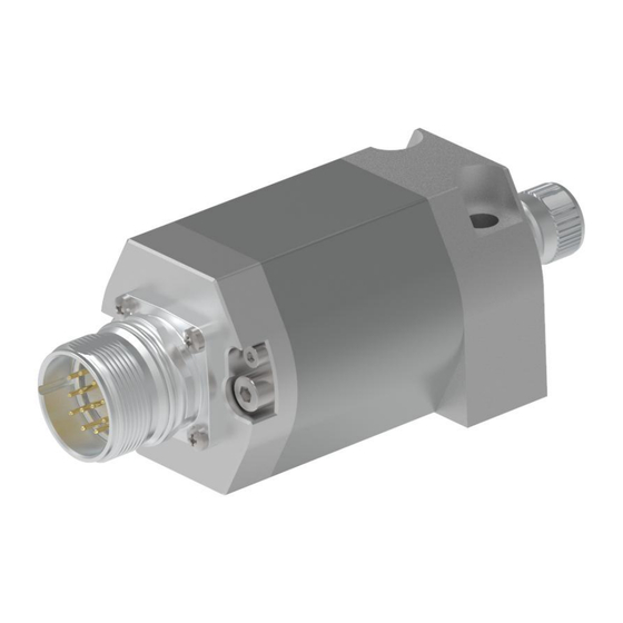
- Seite 134 LMRS_27 Interface-Box SSI Bestellnr.: 341-20001 30.12.2023 / 010201075002999999 Vorteile Abgesetzte Schnittstelle Flexible Programmierung Kundenspezifische Lösungen Misst lineare Bewegungen Nur Interfacebox Positionswert - Justage Sensor separat bestellen Verschleißfreie Abtastung Technische Daten zu 341-20001 AUFLOESUNG 0,01 mm MESSLAENGE 0,00 mm SCHNITTSTELLE CODE...
- Seite 135 LMRS_27 Interface-Box SSI Bestellnr.: 341-20001 30.12.2023 / 010201075002999999 Technische Daten zu 341-20001 Fortsetzung ARBEITSTEMPERATUR 0-70°C OPTION-LA PRESET PROGRAMMIERBAR TRWINPROG STECKERBELEGUNGSNR PARAMETER FILE 5874.TR ZEICHNUNGSNR 04-K341-V0003 SOFTNR 5874 VERSIONSNR DOKUMENTATIONS-NR DOKUMENTE ECCN: Allgemeine Daten zu K-LMRS27-SSI-1 Versorgung - Versorgungsspannung 24 VDC, -20…+10 % Stromaufnahme ohne Last <= 100 mA...
-
Seite 136: Umgebungsbedingungen
LMRS_27 Interface-Box SSI Bestellnr.: 341-20001 30.12.2023 / 010201075002999999 Allgemeine Daten zu K-LMRS27-SSI-1 Fortsetzung SSI - Schnittstelle - SSI-Takteingang Optokoppler - SSI-Datenausgang RS-422, 2-Draht - SSI-Taktfrequenz 95…1000 kHz - SSI-Monozeit, typisch 20 µs Parameter/Funktionen, änderbar Auflösung Ausgabecode Ausgabeformat Fehlermeldung Preset-Parameter Synchronisation Zählrichtung... - Seite 137 LMRS_27 Interface-Box SSI Bestellnr.: 341-20001 30.12.2023 / 010201075002999999 Umgebungsbedingungen Fortsetzung - davon abweichend Anwendung unter UL Bed.: +75°C Lagertemperatur, trocken -40…+80 °C Relative Luftfeuchte 98 %, keine Betauung Schutzart - Standard IP65 Magnetisches Störfeld DIN EN 61000-4-8 Schärfegrad 4 Mess-Referenz...