probst POWER PLAN PP Bedienungsanleitung
Screeding machine

Verwandte Anleitungen für probst POWER PLAN PP


Inhaltszusammenfassung für probst POWER PLAN PP
- Seite 1 VM 401 (all models) VM 401 5150.0016/0017/0018/0019 Laying machine Operating instructions Original operating instructions Screeding Machine POWER PLAN 5130.0001...
-
Seite 2: Inhaltsverzeichnis
Operating instructions Conformity 1 Contents Contents ................................2 Conformity ................................5 Safety ..................................6 Information on these operating instructions....................6 Hazard classification ............................6 The structure of the safety information provided in this manual ............6 Description of symbols and warning signs ....................7 Overview of hazard symbols and information signs .................. - Seite 3 Operating instructions Conformity Daily inspections ............................31 5.3.1 Checking the fuel level ..........................31 5.3.2 Checking the engine oil level ........................32 5.3.3 Checking the hydraulic fluid level ......................33 5.3.4 Checking the coolant level ........................33 5.3.5 Cleaning the air filter ..........................34 5.3.6 Checking the accelerator .........................
- Seite 4 If the machine is not used for a longer period of time ............... 66 6.6.2 Disposal ..............................66 Repairing faults ............................. 67 Duty of inspection ............................69 Information on the type plate ........................70 6.10 Information on hiring out PROBST machinery ..................70 4 / 70...
-
Seite 5: Conformity
Electromagnetic compatibility – Requirements for household appliances, electric tools and similar apparatus. Part 2: Resistance. Authorised person for documentation: Name: J. Holderied Address: Probst GreiftechnikVerlegesysteme GmbH; Gottlieb-Daimler-Str. 6; D-71729 Erdmannhausen; Germany Signature, the undersigned: Erdmannhausen, 24.01.2012......................(M. Probst, Managing Director) -
Seite 6: Safety
Operating instructions Safety Safety Information on these operating instructions These operating instructions contain important information on how to properly and safely operate the screeding machine POWER PLAN PP and are intended for the following persons: The machine owner Assistants ... -
Seite 7: Description Of Symbols And Warning Signs
Operating instructions Safety Description of symbols and warning signs These operating instructions may contain any of the following symbols. Danger Failure to implement the measures needed to avoid this danger can lead to death, injury or damage. Dangerous electric voltage Failure to implement the measures needed to avoid this danger can lead to death, injury or damage as a result of high voltage. -
Seite 8: Overview Of Hazard Symbols And Information Signs
Operating instructions Safety Overview of hazard symbols and information signs 8 / 70... - Seite 9 Operating instructions Safety Designation Order number Specialist testing inspection plate 2904.0056 Type plate Joystick operating diagram 2904.0487 Main switch operating diagram 2904.0484 Front 2904.0552 2904.0553 Risk of crushing 2904.0221 (30 mm) 2904.0220 (50 mm) 2904.0107 (80 mm) Crawler chain tension information 2904.0554 Keep at a safe distance from the crawler undercarriage 2904.0555...
-
Seite 10: Maintaining/Caring For Safety Symbols And Information Signs
Meet the same requirements as assistants and operating personnel. Have received corresponding training from Probst or a person authorised by Probst for performing the maintenance and inspection work described in these operating instructions. Personal safety Risk of personal injury and damage to property The machine must only be operated and maintained by qualified personnel! Failure to do so can lead to personal injury and damage to property. -
Seite 11: Personal Safety Equipment
Operating instructions Safety 3.7.1 Personal safety equipment Risk of personal injury Failure to wear corresponding personal safety equipment when working with/on the machine can lead to injury and damage to health. Personnel must wear the corresponding personal safety equipment specified under the national regulations for the respective type of work they are performing. -
Seite 12: Accident Prevention
Operating instructions Safety Accident prevention As well as a the operating instructions, personnel must also observe the relevant applicable national regulations on, e.g. the following topics: Occupational safety Accident prevention Health protection Environmental protection Risk of personal injury and damage to property Failure to observe these safety measures can lead to injury and damage. -
Seite 13: 3.10 Testing The Machine's Operation And Performing A Visual Inspection
Operating instructions Safety 3.10 Testing the machine’s operation and performing a visual inspection 3.10.1 General information Risk of personal injury Dirty and ice-covered steps and platforms can be slip hazards and cause falls. Remove and keep steps, platforms and shoes free from e.g. dirt, mud, ice and snow and wear anti-slip shoes. -
Seite 14: Hydraulic Pipes And Connections
Operating instructions Safety Risk of damage to property Carelessness when driving and working with the machine can lead to damage. Always take account of the machine’s dimensions, which can be found in the “Dimensions” section. Take note of overhead clearances when driving the machine. ... -
Seite 15: Screeding Mode
Operating instructions Safety 3.11.2 Screeding mode To use screeding mode, switch the machine to driving setting 0;please refer to the section “Driving settings and driving mode”. Check the ground’s inclination and load bearing capacity before starting to screed. ... -
Seite 16: 3.14 Maintenance
Do not place any metal objects or tools onto the battery. Only use original Probst spare parts and approved operating fluids. Failure to do so will void the warranty. In winter, only fuel the machine using winter diesel. -
Seite 17: Hydraulic Hoses And Pipes
Operating instructions Safety Risk of personal injury Engine oil and hydraulic fluid can become hot and cause serious burns. Unless stated otherwise, only perform maintenance and inspection work when the machine components are cool. Always wear corresponding personal protective equipment such as acid-resistant gloves. Risk of personal injury Rotating parts can cause injuries. -
Seite 18: 3.16 Loading And Transporting The Machine
Operating instructions Safety 3.16 Loading and transporting the machine. Check the machine’s loading dimensions. Check the transport vehicle’s permissible axle loads, wheel loads and permissible total load. Take note of the dimensions and load bearing capacities of roads and bridges, as well as their overhead and side clearances. -
Seite 19: General Information
Screeding Machine POWER PLAN PP It is prohibited to attach loads to the using ropes, chains or similar The Screeding Machine POWER PLAN PP must not be used on public roads, and is designed only for use on construction and private sites. Warranty The manufacturer does not accept warranty claims that arise from incorrect use, incorrect operation, insufficient maintenance or the use of unapproved operating fluids. -
Seite 20: Overview And Structure
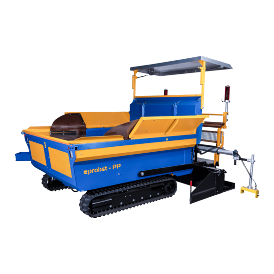
Operating instructions General information Overview and structure Smoothing board See “Raising/lowering the smoothing board” Holder for levelling board, shovel, etc. Measuring bar (folded) See “Overview of safety symbols and information signs”. Holder for MOBA laser receiver See separate operating tips in the section on “Laying and connecting the cable for the laser receiver”. -
Seite 21: Training
Operating instructions General information Tilt sensors The tilt sensors are used for detecting heights when using the ultrasound and laser technology. Fold open the measuring bar (1) by pulling it in the direction of the arrow. Tilt sensor Training The machine must only be operated and maintained by correspondingly trained and briefed personnel. For this reason, personnel will be correspondingly trained and briefed when the machine is handed over. -
Seite 22: Technical Data
Operating instructions General information Technical data Model: POWER PLAN PP Drive power: 26.2 kW / 35.6 PS Engine: Diesel engine V1505-E3B-EU-XL1 Please refer to the engine (KUBOTA) and combined cooler’s (EMMEGI) operating manuals for their technical data Cylinder capacity: 1.498 cm³... -
Seite 23: Dimensions
Operating instructions General information 4.6.1 Dimensions Total length 3665 mm Total height 2623 mm Height of the front chute when open 2089 mm Height up to the driver’s cab 1930 mm Height up to the hopper 1172 mm Opening angle of the front chute 60°... - Seite 24 Operating instructions General information Width of front chute 2090 mm Height up to the driver’s cab step 521 mm Width of the main board 2050 mm Width of the main board when extended with 2 extension boards 2750 mm Width of the main board when extended with 2 extension boards and 2 3450 mm smoothing boards Width with chutes folded out at the side...
-
Seite 25: Operating The Machine
Operating instructions Operating the machine Operating the machine Risk of personal injury and damage to property Failure to observe the instructions in the introductory sections of these instructions can lead to injury and damage. The information provided in the “Safety” and “General information” sections in particular must be observed. -
Seite 26: Driver's Cab
Operating instructions Operating the machine Driver’s cab 5.1.1 Overview of the driver’s cab Joystick (for driving forwards, backwards and sideways) See “Steering”. See “MOBA control unit”. MOBA control unit Operating equipment and indicators See “Operating equipment and indicators”. EMERGENCY STOP button (3 x) Manual control unit See “Manual control unit”. -
Seite 27: Operating Equipment And Indicators
Operating instructions Operating the machine 5.1.2 Operating equipment and indicators Raise the smoothing board on the left Coolant temperature See “Coolant temperature indicator”. Oil pressure control light See “Oil pressure control light”. Preignition indicator See “Starting the engine”. Battery control light See “Battery control light”. -
Seite 28: Manual Control Unit
Operating instructions Operating the machine 5.1.3 Manual control unit The manual control unit can be fastened to the magnetic plates on both the right and left side of the driver’s cab. EMERGENCY STOP button Open/close the right hopper flap Direction correction for “Automatic”... -
Seite 29: Engine Compartment
Operating instructions Operating the machine Engine compartment 5.2.1 Opening the engine hood Risk of personal injury Because of the weight of the front chute, there is a risk of injury when manually opening the engine hood. The front chute must only be opened partway and with the help of another person. Opening the engine hood hydraulically 1. -
Seite 30: Overview Of The Engine Compartment
Operating instructions Operating the machine 5.2.2 Overview of the engine compartment Battery See “Maintaining the battery”. Main switch See “Main switch”. Dipstick for checking the oil level See “Checking the oil level”. Air filter See “Cleaning the air filter”. Throttle valve for adjusting the damper speed for the See “Adjusting the damper speed for the front front chute chute”. -
Seite 31: Daily Inspections
Operating instructions Operating the machine Daily inspections 5.3.1 Checking the fuel level Risk of damage to property The use of fuels that do not comply with the requirements of the European standard EN 590 can lead to increased wear and damage the engine. Do not use any of the following fuels: ... -
Seite 32: Checking The Engine Oil Level
Operating instructions Operating the machine 5.3.2 Checking the engine oil level 1. Park the machine on level ground, switch it off and leave to cool for around 5 minutes. 2. Open the engine hood. See “Opening the engine hood”. 3. Pull out the dipstick (1) and clean with a lint-free, clean cloth. -
Seite 33: Checking The Hydraulic Fluid Level
Operating instructions Operating the machine 5.3.3 Checking the hydraulic fluid level 1. Park the machine on level ground. 2. Open the engine hood. See “Opening the engine hood”. 3. Check the hydraulic fluid level at the fluid level indicator (1). ... -
Seite 34: Cleaning The Air Filter
Operating instructions Operating the machine 1. Park the machine on level ground. 2. Open the engine hood. See “Opening the engine hood”. 3. Carefully unscrew the cap (1) and allow the excess pressure to escape. 4. Carefully continue unscrewing the cap (1) and remove. - Seite 35 Operating instructions Operating the machine 4. Pull out the air filter (4). 5. Blow dry, compressed air (max. 5 bar) into the inside of the air filter (4) until there is no longer any dust coming out of it. 6. Check each of the paper profiles for tears and holes using a suitable flashlight.
-
Seite 36: Checking The Accelerator
Operating instructions Operating the machine 5.3.6 Checking the accelerator Move the accelerator (1) to the left and right dead stop. The accelerator (1) must be easy to move. Before starting the machine 5.4.1 Main switch Risk of accident Failure to use the machine correctly and appropriately can lead to accidents - as can its use by authorized persons. -
Seite 37: Switching On The Main Switch
Operating instructions Operating the machine Switching off the main switch 2. Turn the lever (2) anticlockwise until it is in position (3) and remove. Switching on the main switch 3. Insert the lever in position (3) and turn clockwise. 4. Flip back the headlight (1). Operation 5.5.1 Inspections to be performed before starting the engine... - Seite 38 Operating instructions Operating the machine Battery control light The battery control light (1) must be illuminated when the ignition switch is set to I. See the section on “Starting the engine“. When the engine is running, this control light must extinguish. If it does not, there is a fault.
-
Seite 39: Starting The Engine
Operating instructions Operating the machine Operating hours indicator To observe the specified operating-hour based maintenance intervals, they must be regularly checked at the operating hours indicator (1). 5.5.2 Starting the engine Risk of personal injury Sudden machine movements can lead to injuries. ... -
Seite 40: Controlling Engine Speed
Operating instructions Operating the machine 5. If the machine is in automatic mode, it will make a signal sound. Push the toggle switch (2) down. 6. Push the toggle switch (2) up. Screeding Machine POWER PLAN PP is now ready to be driven. Risk of damage to property If the warning lights fail to extinguish, there is a fault. -
Seite 41: Adjusting The Damper Speed For The Front Chute
Operating instructions Operating the machine 5.5.4 Adjusting the damper speed for the front chute Depending on the operating method and operator’s speed, the damper speed of the front chute can either be increased or reduced. Throttle valve (1) = Raises the front chute. - Seite 42 Operating instructions Operating the machine Manual driving mode 1. Switch toggle switch (1) to 0. 2. Switch toggle switch (2) to 0. Automatic driving mode 1. Switch toggle switch (1) to 0. 2. Switch toggle switch (2) to I. 3. Switch toggle switch (4) on the manual control unit on.
-
Seite 43: Starting To Drive
Operating instructions Operating the machine 5.5.6 Starting to drive Risk of accident Lack of attention when starting to drive the machine in driving mode can lead to accidents. In the event of danger, warn people accordingly using hand signals. ... -
Seite 44: Fitting/Removing The Smoothing And Spreading Board
Operating instructions Operating the machine 1. Undo the wing screw (1). 2. Pull out the chain guide (2) to the required length. 3. Let the chain (3) drop. 4. Tighten the wing screw (1). 5.5.8 Fitting/removing the smoothing and spreading board The smoothing and spreading board can be attached on the left and right side of the machine. -
Seite 45: Adjusting The Adjustable Panels
Operating instructions Operating the machine 5.5.9 Adjusting the adjustable panels The adjustable panels are located on the left and right side of the machine. 1. Pull out the lock bolt (1) and turn. Move the adjustable panel (2) into the required position. A detailed description of how the adjustable panel can be adjusted during operation can be found in... -
Seite 46: Switching The Machine Off
Operating instructions Operating the machine 5.5.11 Switching the machine off 1. Park the machine on solid and even ground. 2. If parked on an incline, protect the machine from moving. 3. Fully lower the smoothing board. See “Raising/lowering the smoothing board” 4. -
Seite 47: Preparing The Machine For Transport
Operating instructions Operating the machine 5.6.2 Preparing the machine for transport 1. Completely empty the hopper. 2. Collapse the adjustable panels. See “Adjusting the adjustable panels”. 3. Fold up the sideway extensions of the chutes. 4. Take down the smoothing and spreading board. -
Seite 48: Loading And Transporting The Machine
Operating instructions Operating the machine 5.6.4 Loading and transporting the machine. Risk of accident If the machine is driven onto the transport vehicle pointing forward and the angle of the ramps is too step, there is a risk of accidents. ... - Seite 49 Operating instructions Operating the machine Lashing eyes Risk of accident Failure to tie down the machine can lead to accidents. Tie down the machine at the specified lashing eyes to prevent it from sliding around on the platform and from tilting over. Tie the machine to the 4 lashing eyes (1) using chain tensioners or tension belts.
-
Seite 50: Lifting The Machine
The machine must only be lifted with suitable and adequately dimensioned lifting gear at the lifting eyes described below. Suitable lifting gear can be obtained and ordered from Probst. The stated chain lengths must be observed. ... -
Seite 51: Maintenance And Care
Only use original spare parts and approved operating fluids. Failure to do so will void the warranty. Probst only accepts warranty claims if the machine has been maintained as specified. See the enclosed maintenance record. Always include a copy of the maintenance record when making a claim under warranty. -
Seite 52: Maintenance Intervals
Operating instructions Maintenance and care Maintenance intervals Mechanical components Maintenance interval Maintenance work to be performed First inspection after 50 ● Check all fastening screws and retighten if necessary. Observe the tightening operating hours torques. Every 50 operating hours Retighten all fastening screws. -
Seite 53: Maintenance Plan
Operating instructions Maintenance and care Maintenance plan Regular maintenance operations The separate operating manual for the engine (KUBOTA), the combination cooler (EMMEGI) and the crawler undercarriage (TFW) must also be observed. Maintenance work Daily First 50 h Every Every Annually Every 2 200 h 1000 h... -
Seite 54: Cleaning
Operating instructions Maintenance and care Cleaning Risk of personal injury Cleaning the machine when it is at operating temperature can lead to serious injury. Only clean the machine with the engine switched off and once all components have cooled down. Risk of personal injury There is an increased risk of slipping and falling when cleaning the machine. -
Seite 55: Cleaning The Machine With A Pressure Washer
Operating instructions Maintenance and care 6.3.3 Cleaning the machine with a pressure washer If the machine is heavily soiled, including with oil and fuel: Keep the pressure washer’s nozzle at least 300 mm away from the machine. The pressure washer’s jet pressure must not exceed 100 bar. ... -
Seite 56: Lubricating
Operating instructions Maintenance and care Lubricating For maintenance intervals, see “Maintenance plan”. Thoroughly clean the lubrication points. Keep adding lubricant until it starts to exit from the relevant openings. See “Technical data” for information on operating fluids and filling capacities. 56 / 70... -
Seite 57: Maintenance Work
Changing the engine oil and oil filter The first oil and oil filter change is due after the first 50 operating hours and must be performed by Probst customer services. Thereafter, the oil and oil filter must be changed every 200 operating hours. -
Seite 58: Maintaining The Crawler Tracks
Operating instructions Maintenance and care 1. Open the engine hood. See “Opening the engine hood”. 2. Press onto the v-belt (1) with your thumb. The v-belt should give by about 7-9 mm (A) when pressed down. 3. If necessary, get the v-belt tensioned by customer services. -
Seite 59: Maintaining The Battery
Operating instructions Maintenance and care Tensioning/loosening the crawler chain Loosening 1. Unscrew the cover panel (1). 2. Keep unscrewing the valve (2) until lubricant starts to exit. 3. Allow lubricant to exit until (A) has reached the correct dimensions. 4. Tighten the valve (2). Tightening torque 40-60 Nm. - Seite 60 Operating instructions Maintenance and care Connecting and disconnecting the battery Risk of personal injury There is a risk of short circuiting and sparking when connecting and disconnecting the battery. Only connect and disconnect the battery if the electrical system has been switched off at the main switch.
-
Seite 61: Charging The Battery
Operating instructions Maintenance and care Charging the battery Risk of personal injury and damage to property Failure to properly charge empty or frozen batteries can lead to injury and damage. Empty batteries can already start to freeze at temperatures of -10 °C. ... - Seite 62 Operating instructions Maintenance and care 1. Open the engine hood. See “Opening the engine hood”. 2. Remove the protective cap from the positive terminal. 3. Connect the positive lead (1) to the positive terminal on the second battery. 4. Connect the positive lead (1) to the positive terminal (2).
-
Seite 63: Changing Fuses
Operating instructions Maintenance and care 6.5.8 Changing fuses Risk of damage to property Faulty fuses can cause damage to the electrical system. Repair the fault that damaged the fuse. Replace the fuse immediately and make sure that the new fuse has the right amps. ... - Seite 64 Operating instructions Maintenance and care Fuse assignment diagram Consumer Fuse rating Top terminal box Control voltage (ignition switch) 25 A Glow plugs 25 A Control voltage (downstream of ignition switch) 25 A Starter motor 25 A Lifting magnet 7.5 A Diesel pump 7.5 A Lights...
-
Seite 65: Changing Light Bulbs
Operating instructions Maintenance and care 6.5.9 Changing light bulbs Risk of personal injury and damage to property Light bulbs and lamp holders become hot when the lights are switched on. They can cause burns if touched and can ignite flammable objects. ... -
Seite 66: If The Machine Is Not Used For A Longer Period Of Time / Disposing Of The Machine
Operating instructions Maintenance and care If the machine is not used for a longer period of time / disposing of the machine 6.6.1 If the machine is not used for a longer period of time If the machine will not be used for more than 2 months: ... -
Seite 67: Repairing Faults
Operating instructions Maintenance and care Repairing faults Risk of personal injury and damage to property Faults can lead to injury and damage. If there is a fault, stop the machine as quickly as possible and make it safe. Establish the cause of the fault and repair it immediately. - Seite 68 Operating instructions Maintenance and care Fault Cause Remedy Automatic driving mode The machine is set to drive ● Switch the drive setting switch to I. See “Drive does not work. setting 0. settings and driving mode”. The toggle switch on the ●...
-
Seite 69: Duty Of Inspection
This inspection must be documented in writing. Probst recommends attaching the specialist testing inspection plate in a clearly visible place on the machine once the inspection has been completed and any faults repaired. See “Overview of safety symbols and information signs”. Label 1. -
Seite 70: Information On The Type Plate
6.10 Information on hiring out PROBST machinery All PROBST machinery must be supplied with the associated original operating instructions if hired out. If the instruction manual’s language differs from the language of the relevant country of use, the original operating instructions must be translated into the relevant language and the translation supplied with the machinery. - Seite 73 41300004 * siehe separate Liste see separate list 41300005 * siehe separate Liste see separate list 41300006 * 20060001 siehe separate Liste 33100105 see separate list 41300107 Hydraulikzylinder 50/25 - 300Hub siehe Hydraulikschaltplan see circuit diagramm 41300079 41300057 siehe separate Liste see separate list 41300026 siehe separate Liste...
- Seite 92 20400011 22160056 20400039 30300021 20530014 22210073 Bei Änderungen Rücksprache TB ! Gewicht: 7,8 kg Schutzvermerk nach DIN 34 beachten! Nachdruck nur mit unserer Genehmigung! Benennung Datum Name HD-Zylinder vormontiert für Erst. 24.2.2011 M.Kaltenbach Bunkerklappe an Flächen- Gepr. fertiger PP Blatt Artikelnummer/Zeichnungsnummer E41300106 Kunde:...
- Seite 101 1) Beide Drosselventil der Nivellierzylinder so einstellen, dass diese in 10 Sek. komplett ausgefahren sind. Darf vom Kunden nicht verstellt werden! 22070071 2) Drosselrückschlagventile der Frontklappe ca. 3 1/2 Umdrehungen öffnen Vorsteuerblock HC-RCX (4xA17 -Steuerschiber) (22400010) 3) Drosselventil für HC-RCX ca. 1 1/2 Umdrehungen öffnen 22210073 Fahrschiff HD-Zylinder 50/30-150Hub...
- Seite 102 Anlagenbezeichnung: 51300001 - Flächenfertiger Power Plan Projektnummer 10 06 241 Kunde Probst Greiftechnik Kundennummer 10 06 241 Zeichnungsnummer : 500-9-10-06-24 Hersteller-Firma 1: HSE Jürgen Schäfer Schaltschränke Rittal RAL 7035 D-73553 Pfahlbronn Einspeisung Motor Zuleitung Hersteller-Firma 2: Probst Greiftechnik Steuerspannung 12V DC...
- Seite 103 HBG im Plan der Fa. ibl hydronik Schaltplan. Steuerspannungen sind in dbl 1,5qmm auszuführen. Ventile Sicherheitsschalter Niveau Trittbrett Datum Probst Greiftechnik Blockbild 500-9-10-06-24 HSE Jürgen Schäfer Bearb. 51300001 - Flächenfertiger Power Plan D-73553 Pfahlbronn Gepr. 02.02.11 10 06 241 Änderung...
- Seite 104 Batterie Anlasser pumpe Licht- maschine Fahrzeug- Fahrzeug- Fahrzeug- Fahrzeug- masse masse masse masse Datum Probst Greiftechnik Basis 1 500-9-10-06-24 HSE Jürgen Schäfer Bearb. 51300001 - Flächenfertiger Power Plan D-73553 Pfahlbronn Gepr. 02.02.11 10 06 241 Žnderung Datum Name Norm Urspr.
- Seite 105 87 20.4 87 .6 -H12 -H13 Hupe Fahr- Lampe Lampe stufe vorne vorne I + II Probst Greiftechnik Datum Basis 2 500-9-10-06-24 HSE Jürgen Schäfer Bearb. 51300001 - Flächenfertiger Power Plan D-73553 Pfahlbronn Gepr. 02.02.11 10 06 241 Žnderung Datum...
- Seite 106 W101 Ölflex110 18x2,5qmm W102 ™lflex110 18x2,5qmm -KK1 Klemmenkasten Motorraum Not-Aus VDO-Sensor! 2 21.9 2 21.9 -S14 Datum Probst Greiftechnik Basis 3 500-9-10-06-24 HSE Jürgen Schäfer Bearb. D-73553 Pfahlbronn 51300001 - Flächenfertiger Power Plan Gepr. 02.02.11 10 06 241 Žnderung Datum...
- Seite 107 WY2 Murr 3x0,5qmm WY8 Murr 3x0,5qmm WY9 Murr 3x0,5qmm Fahren Fahren Frontrutsche Frontrutsche heben senken Datum Basis 2 500-9-10-06-24 Probst Greiftechnik HSE Jürgen Schäfer Bearb. 51300001 - Flächenfertiger Power Plan D-73553 Pfahlbronn Gepr. 02.02.11 10 06 241 Žnderung Datum Name Norm Urspr.
- Seite 108 Bunkerklappe Bunkerklappe Bunkerklappe links links rechts rechts heben senken heben senken Datum Basis 2 500-9-10-06-24 Probst Greiftechnik HSE Jürgen Schäfer Bearb. D-73553 Pfahlbronn 51300001 - Flächenfertiger Power Plan Gepr. 02.02.11 10 06 241 Žnderung Datum Name Norm Urspr. Ers.f. Ers.d.
- Seite 109 -Y17 -Y20 -Y21 -Y16 Bole Freigabe Ventil Ventil Not-Aus heben (Option) Datum Basis 2 500-9-10-06-24 Probst Greiftechnik HSE Jürgen Schäfer Bearb. D-73553 Pfahlbronn 51300001 - Flächenfertiger Power Plan Gepr. 02.02.11 10 06 241 Žnderung Datum Name Norm Urspr. Ers.f. Ers.d.
- Seite 110 Blindstecker Not-Aus WS3 ™lflex 110 3x1,5qmm WS2 ™lflex 110 3x1,5qmm Not-Aus Not-Aus Links Rechts Datum Not-Aus / Fahrfreigabe 500-9-10-06-24 Probst Greiftechnik HSE Jürgen Schäfer Bearb. D-73553 Pfahlbronn 51300001 - Flächenfertiger Power Plan Gepr. 02.02.11 10 06 241 Žnderung Datum Name Norm Urspr.
- Seite 111 Nivau Nivau Nivau links links rechts rechts heben senken heben senken Datum Steuerung Nivau 500-9-10-06-24 Probst Greiftechnik HSE Jürgen Schäfer Bearb. D-73553 Pfahlbronn 51300001 - Flächenfertiger Power Plan Gepr. 02.02.11 10 06 241 Žnderung Datum Name Norm Urspr. Ers.f. Ers.d.
- Seite 112 -X100 -X102 -X104 -X103 -X101 R120 als Busabschluss R120 als Busabschluss Mehr zum Lasersystem siehe MOBA Schaltpaln 27.01.2010/V1.00 Datum Probst Greiftechnik Steuerung Laser 500-9-10-06-24 HSE Jürgen Schäfer Bearb. 51300001 - Flächenfertiger Power Plan D-73553 Pfahlbronn Gepr. 02.02.11 10 06 241 Änderung...
-
Seite 113: Ersatzteile / Spare Parts Powerplan Pp
Ersatzteile / Spare Parts POWERPLAN PP Hersteller & Bezeichnung Filterübersicht POWERPLAN PP (Bestellnummer) Filter overview POWERPLAN PP Art.-Nr. Manufacturer&Designation (Order-Number) Motorölfilter Engine oil filter 26900019 Digöma - D105-BB-EC-1 Kraftstofffilter(Vorfilter) 26900022 Digöma - KL 63 (LH1) Fuel filter (prefilter) Kraftstoff-Filter-Einsatz 26900018 Digöma - DGM/K03185 Fuel filter cartridge Luftfilter-Einsatz... -
Seite 115: Spare Parts List
Bedienungs - Operating and Instructions de service maintenance et entretien Wartungsanweisung instructions Ersatzteilliste Spare parts list Catalogue de pièces Serie - Nr. 1354-17 Serial - nr. N° de série Fahrantrieb Typ Track drive type Engrenage de chenille 702C2K - MAG 26VP- 4 702C2K - MAG 26VP- 4 702C2K - MAG 26VP- 4 Bauklasse 1.7 - 2.7... - Seite 116 BEDIENUNGSANLEITUNG OPERATING INSTRUCTIONS INSTRUCTION DE SERVICE TFW - FAHRTECHNIK AG Taf. Fig. Bedienung Operation Utilisation Plan. Bedienungs - Informationen Operating instructions Instructions de entretien 00.10.010 Aufbau, Benennung Construction and naming Safety Construction et dénomination 00.10.040 measures Mesures de sécurité Sicherheitsmaßnahmen 00.10.080 Prevention of accidents Prévention des accidents...
-
Seite 117: Mit Allen Zur Bedienung Notwendigen Informationen Vertraut Machen
BEDIENUNGSANLEITUNG OPERATING INSTRUCTIONS INSTRUCTION DE SERVICE TFW - FAHRTECHNIK AG Mit allen zur Bedienung First familiarise yourself with Pour se familiariser avec notwendigen Informationen all the information you need toutes les informations vertraut machen to operate the equipment nécessaires pair l'utilisation •... -
Seite 118: Aufbau, Benennung Und Verwendungszweck Des Raupenfahrwerkes
BEDIENUNGSANLEITUNG OPERATING INSTRUCTIONS INSTRUCTION DE SERVICE TFW - FAHRTECHNIK AG Aufbau, Benennung Construction, naming and Construction, dénomination und Verwendungszweck purpose of the undercarriage et finalité du train de chenille des Raupenfahrwerkes © Copyright by TFW - Fahrtechnik Serie - Nr. Serial - nr. -
Seite 119: Sicherheitsmaßnahmen Beim Allgemeinen Einsatz Von Raupenfahrwerken
BEDIENUNGSANLEITUNG OPERATING INSTRUCTIONS INSTRUCTION DE SERVICE TFW - FAHRTECHNIK AG Sicherheitsmaßnahmen Safety measures for Mesures de sécurité pour general use of the track l'emploi général des trains beim allgemeinen Einsatz chains des chenilles von Raupenfahrwerken © Copyright by TFW - Fahrtechnik •... -
Seite 120: Unfallverhütungs-Massnahmen Beim Einsatz Von Raupenfahrwerken
BEDIENUNGSANLEITUNG OPERATING INSTRUCTIONS INSTRUCTION DE SERVICE TFW - FAHRTECHNIK AG Unfallverhütungs- Safety measures Mesures pour Massnahmen beim Einsatz when working lévitation des von Raupenfahrwerken with crawler machines accidents • Unachtsamkeit ist die häufigste • Lack of attention is the main ac- •... -
Seite 121: Vorsichtsmaßnahmen Beim Einsatz Von Gummiraupenbänder
BEDIENUNGSANLEITUNG OPERATING INSTRUCTIONS INSTRUCTION DE SERVICE TFW - FAHRTECHNIK AG Vorsichtsmaßnahmen Safety measures Mesures de sécurité beim Einsatz von when working with dans l'emploi des Gummiraupenbänder rubber tracks bandes en caoutchouc • Vermeiden Sie das Überfahren • Avoid passing over sharp mate- •... -
Seite 122: Kippgefahr Beim Fahren An Hängen Beachten Parken An Hängen
BEDIENUNGSANLEITUNG OPERATING INSTRUCTIONS INSTRUCTION DE SERVICE TFW - FAHRTECHNIK AG Kippgefahr beim Fahren There is a risk of overturning Risque de renversement an Hängen beachten when travelling on slopes en cas conduite sur pentes Parken an Hängen Parking on slopes Arrêt sur pentes ©... -
Seite 123: Aufladen Des Gerätes Mit Raupenfahrwerk
BEDIENUNGSANLEITUNG OPERATING INSTRUCTIONS INSTRUCTION DE SERVICE TFW - FAHRTECHNIK AG Aufladen des Gerätes Loading on to transport Charge d'une machine mit Raupenfahrwerk machine with crawler tracks sur chenilles © Copyright by TFW - Fahrtechnik • • Ramps width to be at least •... -
Seite 124: Transport Des Gerätes Mit Raupenfahrwerk
BEDIENUNGSANLEITUNG OPERATING INSTRUCTIONS INSTRUCTION DE SERVICE TFW - FAHRTECHNIK AG Transport des Gerätes Machine- / vehicle Transport de la machine mit Raupenfahrwerk Transport sur chenilles • Maximale Höhe (A): je nach • Maximum height (A): depends • Hauteur max. (A): selon la Transportstellung des Gerätes, on machine' s transport posi- position de transport et... -
Seite 125: Abladen Des Gerätes Mit Raupenfahrwerk
BEDIENUNGSANLEITUNG OPERATING INSTRUCTIONS INSTRUCTION DE SERVICE TFW - FAHRTECHNIK AG Abladen des Gerätes Unloading of a machine Décharge d'une mit Raupenfahrwerk with crawler tracks machine sur chenilles © Copyright by TFW - Fahrtechnik • Ladeflächen und Rampen wie • Secure surfaces and ramps as •... - Seite 126 BEDIENUNGSANLEITUNG OPERATING INSTRUCTIONS INSTRUCTION DE SERVICE TFW - FAHRTECHNIK AG Sicherheitsanweisungen Safety instructions Instructions de Sécurité Standsicherheit Ensure stability Stabilité • Erst die Wartungsanweisung • First read the maintenance • Lire les instructions avant de lesen, dann die Wartungsarbeit instructions, then perform réaliser les travaux.
-
Seite 127: Raupenkette / Raupenband Spannung Kontrollieren
BEDIENUNGSANLEITUNG OPERATING INSTRUCTIONS INSTRUCTION DE SERVICE TFW - FAHRTECHNIK AG Raupenkette / Raupenband Checking rubber - or steel Contrôle de la Spannung kontrollieren crawler tension chaîne / bande © Copyright by TFW - Fahrtechnik • Alle 100 Betriebsstunden. • Check every 100 operating •... - Seite 128 BEDIENUNGSANLEITUNG OPERATING INSTRUCTIONS INSTRUCTION DE SERVICE TFW - FAHRTECHNIK AG Raupenkette / Raupenband Loosening Detensionner la lockern crawler track chaîne / bande © Copyright by TFW - Fahrtechnik • Deckel (1) abschrauben. • Unscrew cover (1). • Dévisser couvercle (1). •...
- Seite 129 BEDIENUNGSANLEITUNG OPERATING INSTRUCTIONS INSTRUCTION DE SERVICE TFW - FAHRTECHNIK AG Raupenkette / Raupenband Tension rubber - or steel Comment tensionner la spannen crawler track chaîne / bande ou caoutchouc © Copyright by TFW - Fahrtechnik • Deckel (1) abschrauben. • Unscrew cover (1). •...
-
Seite 130: Spannrichtung
BEDIENUNGSANLEITUNG OPERATING INSTRUCTIONS INSTRUCTION DE SERVICE TFW - FAHRTECHNIK AG Federspannpaket Tension unit Dispositif de serrage Kontroll - und check up and Instructions de contrôle Wartungs - Informationen maintenance instructions et entretien. Spannrichtung Tension Range Direction de tension © Copyright by TFW - Fahrtechnik •... -
Seite 131: Ölstand Kontrollieren Alle 250 Betriebsstunden
BEDIENUNGSANLEITUNG OPERATING INSTRUCTIONS INSTRUCTION DE SERVICE TFW - FAHRTECHNIK AG Ölstand kontrollieren Check oil level Contrôler niveau d'huile alle 250 Betriebsstunden every 250 operating hours. chaque 250 heures de travail Füllhöhe Level Niveau • Verschluss-Schraube (2) • Unscrew plug (2). •... - Seite 132 BEDIENUNGSANLEITUNG OPERATING INSTRUCTIONS INSTRUCTION DE SERVICE TFW - FAHRTECHNIK AG Fahrantrieb Ölwechsel Travel gear renewing oil Echange d'huile engrenage planétaire chaque 1000 heures alle 1000 Betriebsstunden every 1000 operating hours Protégez l'environnement Umweltschutz beachten Protect environment • Spätestens jedoch nach •...
- Seite 133 BEDIENUNGSANLEITUNG OPERATING INSTRUCTIONS INSTRUCTION DE SERVICE TFW - FAHRTECHNIK AG Schraubensitz Checking firm seating Contrôler kontrollieren of screws serrage des vis © Copyright by TFW - Fahrtechnik • Befestigungsschrauben der bei- • Check attachment for both drive • Contrôler les vis (7) des deux den Antriebskränze (7) kon- sprockets (7): jante dentée:...
-
Seite 134: Ersatzteilliste
ERSATZTEILLISTE SPARE PARTS LIST CATALOGUE DE PIECES TFW-FAHRTECHNIK AG Ersatzteilliste Spare parts list Catalogue de pièces © Copyright by TFW - Fahrtechnik • Bestellbeispiel: • Specimen order: • Exemple de commande: • (Bildtafel 17.30.003, Pos. N° 8) • (Fig. No.17.30.003,Pos. No° 8) •... - Seite 135 ERSATZTEILLISTE SPARE PARTS LIST CATALOGUE DE PIECES TFW-FAHRTECHNIK AG BEST. NR. BENENNUNG DESCRIPTION DESIGNATION BEMERKUNG ORD. NO. REMARK, REMARQUE 1220.113 FAHRWERK UNDERCARRIAGE TRACTION A CHENILLE POS.1 - 3 KOMPLETT COMPLETE COMPLET RAUPENFAHRWERK TRACK ASSEMBLY TRACTION A CHENILLE BONFIGLIOLI 17.30.003 /1 6 - ROLLIG 6 - ROLLER TYPE 6 - POULIE TYPE...
- Seite 136 ERSATZTEILLISTE SPARE PARTS LIST CATALOGUE DE PIECES TFW-FAHRTECHNIK AG BEST. NR. BENENNUNG DESCRIPTION DESIGNATION BEMERKUNG ORD. NO. REMARK, REMARQUE 1171.061 FAHRSCHIFF TRACK SIDEFRAME TRACTION A CHENILLE POS. 1 - 17 KOMPLETT LINKS COMPLETE LEFT COMPLETE GAUCHE 1171.062 FAHRSCHIFF TRACK SIDEFRAME TRACTION A CHENILLE POS.
- Seite 137 BEDIENUNGSANLEITUNG OPERATING INSTRUCTIONS INSTRUCTION DE SERVICE TFW - FAHRTECHNIK AG © Copyright by TFW - Fahrtechnik Best. NR. BENENNUNG DESCRIPTION DESIGNATION BEMERKUNG ORD. NO. REMARK, REMARQUE 1002.010 LAUFROLLE KPL. ROLLER CPL. POULIE COMPLETE REF. 1001.02 POS. 1 - 7 1002.600 DECKSCHEIBE WASHER RONDELLE...
- Seite 138 ERSATZTEILLISTE SPARE PARTS LIST CATALOGUE DE PIECES TFW-FAHRTECHNIK AG © Copyright by TFW - Fahrtechnik BEST. NR. BENENNUNG DESCRIPTION DESIGNATION BEMERKUNG ORD. NO. REMARK, REMARQUE 1004.010 LEITRAD IDLER ROUE DE GUIDAGE POS. 1 - 9 1019.502 SPANNHUELSE ADAPTOR SLEEVE DOUILLE DE SERRAGE 10 x 50 1004.500 LAGERBOCK...
- Seite 139 ERSATZTEILLISTE SPARE PARTS LIST CATALOGUE DE PIECES TFW-FAHRTECHNIK AG © Copyright by TFW - Fahrtechnik BEST. NR. BENENNUNG DESCRIPTION DESIGNATION BEMERKUNG ORD. NO. REMARK, REMARQUE 1135.004 SPANNPAKET KPL. ADJUSTING DISPOSITIV DE SERRAGE Kl. 1.7 / Pos. 1 - 8 DEVICE 1018.606 SICH.
- Seite 140 ERSATZTEILLISTE SPARE PARTS LIST CATALOGUE DE PIECES TFW-FAHRTECHNIK AG POS. BEST. NR. BENENNUNG DESCRIPTION DESIGNATION BEMERKUNG ORD. NO. REMARK, REMARQUE 1007.135 FAHRANTRIEB KPL. TRACK GEAR CPL. ENGRENAGE PLANETAIRE POS. 1 - 3 WITH AVEC HYDRAULIK-MOTOR HYDRAULIC MOTOR MOTEUR HYDRAULIQUE AND COUNTER BALANCE VALVE SECTION DE SOUPAPE FAHR - BREMSVENTIL...
- Seite 141 ERSATZTEILLISTE SPARE PARTS LIST CATALOGUE DE PIECES TFW-FAHRTECHNIK AG © Copyright by TFW - Fahrtechnik BEST. Nr. BENENNUNG DESCRIPTION DESIGNATION BEMERKUNG ORD. NO. REMARK, REMARQUE 1130.413 FRONT RECHTS 1130.415 FRONT RIGHT 1130.417 FRONT DROITE 1130.410 NORMALE RIJRICHTING (RECHTS) 1130.414 FRONT LINKS 1130.416 FRONT LEFT 1130.418...
- Seite 142 BEDIENUNGSANLEITUNG OPERATING INSTRUCTIONS INSTRUCTION DE SERVICE TFW - FAHRTECHNIK AG Gewichte, Masse und Weights, dimensions and Poids, dimensions Leistungsdaten performance data et prestations G GB Gewicht Weight Poids Max. Einsatzgewicht Max. operating weight Le poids opérationnel max. 6000 Unterwagen kpl. Undercarriage complete Chariot complet 1 Gummiraupenband...
-
Seite 143: Hydrauliköl, Schmiermittel Und Einsatztemperatur
BEDIENUNGSANLEITUNG OPERATING INSTRUCTIONS INSTRUCTION DE SERVICE TFW - FAHRTECHNIK AG Hydrauliköl, Schmiermittel Huile hydraulique et Engrenage Hydraulic oil, lubricating oil und Einsatztemperatur Température d'utilisation operating temperature G GB Getriebeöl Travel gear oil Engrenage planet. huile Kennzeichnung Identification Identification API - GL 5 API - GL 5 API - GL 5 MIL - L - 2105 B... -
Seite 144: Eg-Einbauerklärung Für Unvollständige Maschinen
EG-Einbauerklärung für unvollständige Maschinen (Maschinenrichtlinie 2006/42/EG, Anhang II, sub. B) - Fahrtechnik AG Hersteller: Adresse: Speerstrasse 26, CH-8853 Lachen / Schweiz Name der Person, welche bevollmächtigt ist, die relevanten technischen Unterlagen zusammenzustellen: Frei Theodor, Speerstrasse 26, CH-8853 Lachen / Schweiz Wir erklären hiermit, dass für die unvollständige Maschine Raupenfahrschiffe und Raupenfahrwerke Beschreibung:... -
Seite 145: Bei Der Montage Der Unvollständigen Maschine
Montageanleitung nach Anhang VI (EG-RL 2006/42/EG) Bei der Montage der bei der Montage des Fahrwerkes müssen alle fachlich und technisch geltenden Vorschriften eingehalten unvollständigen Maschine werden. alle Verbindungen mittels Schweißen oder Schrauben, etc. " Raupenfahrwerk müssen nach den allgemein geltenden Vorschriften ausge- führt werden. -
Seite 146: Sicherheitsmaßnahmen
Sicherheitsmaßnahmen beim allgemeinen Einsatz von Raupenfahrwerken (EG-RL 2006/42/EG) bevor Sie den Motor starten machen Sie einen Kontrollgang um das ganze Gerät herum Bei der Inbetriebnahme bevor Sie den Motor starten vergewissern Sie sich, von einem dass sich auch niemand in der Servicegrube unter dem Gerät aufhält Gerät mit einem niemals den Motor starten, wenn sich jemand unter... -
Seite 147: Verschleiss Und Schäden An Gummiraupen
BEDIENUNGS - OPERATING AND INSTRUCTIONS DE UND WARTUNGS - MAINTENANCE SERVICE ANWEISUNG INSTRUCTIONS ET ENTRETIEN © Copyright by TFW - Fahrtechnik Switzerland Vorsichtsmassnah- Safety measures Mesures de sécurité men beim Einsatz when working dans l'emploi des von Gummiraupen with rubber tracks chenilles caoutchouc Verschleiss Wear and... - Seite 148 BEDIENUNGSANLEITUNG OPERATING INSTRUCTIONS INSTRUCTION DE SERVICE - FAHRTECHNIK AG Verschleiss und Wear and damages Usure et Dommages Schäden an Gummiraupen of rubber crawlers des Bandes en Caoutchouc Fig. 2 Fig. 1 Fig. 1 Casse des fils d'acier Fig. 1 Bruch der Stahllitzen Fig.
- Seite 149 BEDIENUNGSANLEITUNG OPERATING INSTRUCTIONS INSTRUCTION DE SERVICE - FAHRTECHNIK AG Verschleiss und Wear and damages Usure et Dommages Schäden an Gummiraupen of rubber crawlers des Bandes en Caoutchouc Fig. 4 Fig. 3 Fig. 3 Usure et coupages Fig. 3 Verschleiss und Risse Fig.
- Seite 150 BEDIENUNGSANLEITUNG OPERATING INSTRUCTIONS INSTRUCTION DE SERVICE - FAHRTECHNIK AG Verschleiss und Wear and damages Usure et Dommages Schäden an Gummiraupen of rubber crawlers des Bandes en Caoutchouc Fig. 6 Fig. 5 Fig. 5 Äußere Risse in Fig. 5 External tears across and Fig.
- Seite 151 BEDIENUNGSANLEITUNG OPERATING INSTRUCTIONS INSTRUCTION DE SERVICE - FAHRTECHNIK AG Verschleiss und Wear and damages Usure et Dommages Schäden an Gummiraupen of rubber crawlers des Bandes en Caoutchouc Fig. 8 Fig. 7 Fig. 7 Risse auf der Innenseite Fig. 7 Tears on inside near to the Fig.
- Seite 152 BEDIENUNGSANLEITUNG OPERATING INSTRUCTIONS INSTRUCTION DE SERVICE - FAHRTECHNIK AG Verschleiss und Wear and damages Usure et Dommages Schäden an Gummiraupen of rubber crawlers des Bandes en Caoutchouc Fig. 10 INTERCHANGEABLE TYPE CONVENTIONAL TYPE Fig. 9 Fig. 9 / 10 Raupenband Fig.
- Seite 155 MODELS D1105-TE3 D1005-E3 · V1505-E3 D1105-E3 · D1305-E3 · V1505-TE3 1ABABAAAP1500...
- Seite 156 CONTENTS SAFE OPERATION ..................... 1 SERVICING OF THE ENGINE .................. 1 NAMES OF PARTS ....................2 PRE-OPERATION CHECK..................3 BREAK-IN ......................3 DAILY CHECK ....................... 3 OPERATING THE ENGINE..................4 STARTING THE ENGINE(NORMAL) ..............4 COLD WEATHER STARTING ................5 STOPPING THE ENGINE..................
- Seite 157 CONTENTS Dust indicator (optional) ..................... 22 BATTERY......................22 Battery charging......................... 22 Direction for long term storage ..................23 ELECTRIC WIRING ..................... 23 FAN BELT ......................24 Adjusting Fan Belt Tension ....................24 CARRIAGE AND STORAGE ................... 25 CARRIAGE......................25 STORAGE......................25 TROUBLESHOOTING.....................
-
Seite 158: Safety First
FOREWORD You are now the proud owner of a KUBOTA Engine. This engine is a product of KUBOTA quality engineering and manufacturing. It is made of fine materials and under a rigid quality control system. It will give you long, satisfactory service. To obtain the best use of your engine, please read this manual carefully. -
Seite 159: Safe Operation
SAFE OPERATION SAFE OPERATION Careful operation is your best assurance against an accident. Read and understand this section carefully before operating the engine. All operators, no matter how much experience they may have, should read this and other related manuals before operating the engine or any equipment attached to it. - Seite 160 SAFE OPERATION 3. CHECK BEFORE STARTING & OPERATING THE ENGINE A Be sure to inspect the engine before operation. Do not operate the engine if there is something wrong with it. Repair it immediately. A Ensure all guards and shields are in place before operating the engine.
- Seite 161 SAFE OPERATION 6. EXHAUST GASES & FIRE PREVENTION A Engine exhaust fumes can be very harmful if allowed to accumulate. Be sure to run the engine in a well ventilated location and where there are no people or livestock near the engine. A The exhaust gas from the muffler is very hot.
- Seite 162 SAFE OPERATION 8. CAUTIONS AGAINST BURNS & BATTERY EXPLOSION A To avoid burns, be cautious of hot components, e.g. muffler, muffler cover, radiator, hoses, engine body, coolants, engine oil, etc. during operation and after the engine has been shut off. A DO NOT remove the radiator cap while the engine is running or immediately after stopping.
- Seite 163 SAFE OPERATION 10. ANTI-FREEZE & DISPOSAL OF FLUIDS A Anti-freeze contains poison. Wear rubber gloves to avoid personal injury. In case of contact with skin, wash it off immediately. A DO NOT mix different types of Anti-freeze. The mixture can produce a chemical reaction causing harmful substances.
- Seite 164 SAFE OPERATION 11. CONDUCTING SAFETY CHECKS & MAINTENANCE A When inspecting the engine or servicing, place the engine on a large flat surface. DO NOT work on anything that is supported ONLY by lift jacks or a hoist. Always use blocks or the correct stands to support the engine before servicing.
- Seite 165 SAFE OPERATION 12. WARNING AND CAUTION LABELS Part No.19077-8724-1 or 16667-8724-1 (55mm in diameter) (37mm in diameter) Part No.TA040-4957-1 Stay clear of engine fan and fan belt 13. CARE OF WARNING AND CAUTION LABELS 1. Keep warning and caution labels clean and free from obstructing material. 2.
- Seite 166 SAFE OPERATION...
-
Seite 167: Servicing Of The Engine
SERVICING OF THE ENGINE SERVICING OF THE ENGINE Your dealer is interested in your new engine and has the desire to help you get the most value from it. After reading this manual thoroughly, you will find that you can do some of the regular maintenance yourself. However, when in need of parts or major service, be sure to see your KUBOTA dealer. -
Seite 168: Names Of Parts
NAMES OF PARTS NAMES OF PARTS 1ABABAAAP149A (1) Intake manifold (10) Oil filler plug (2) Speed control lever (11) Exhaust manifold (3) Engine stop lever (12) Alternator (4) Injection pump (13) Starter (5) Fuel feed pump (14) Oil level gauge (6) Cooling fan (15) Oil pressure switch (7) Fan drive pulley... -
Seite 169: Pre-Operation Check
PRE-OPERATION CHECK PRE-OPERATION CHECK BREAK-IN During the engine break-in period, observe the following by all means: 1. Change engine oil and oil filter cartridge after the first 50 hours of operation. (See "ENGINE OIL" in "PERIODIC SERVICE" section.) 2. When ambient temperature is low, operate the machine after the engine has been completely warmed up. DAILY CHECK To prevent trouble from occurring, it is important to know the conditions of the engine well. -
Seite 170: Operating The Engine
OPERATING THE ENGINE OPERATING THE ENGINE STARTING THE ENGINE(NORMAL) 1. Set the fuel lever to the "ON" position. CAUTION To avoid personal injury: A Do not allow children to approach the machine while the engine is running. A Be sure to install the machine on which the engine is installed, on a flat place. -
Seite 171: Cold Weather Starting
OPERATING THE ENGINE A If the engine does not catch or start at 10 seconds 4. Insert the key into the key switch and after the starter switch is set at "STARTING" position, turn it "ON". wait for another 30 seconds and then begin the engine starting sequence again. -
Seite 172: Stopping The Engine
OPERATING THE ENGINE STOPPING THE ENGINE CHECKS DURING OPERATION While running, make the following checks to see that all parts are working correctly. 1. Return the speed control lever to low idle, and run the engine under idling BRadiator Cooling water(Coolant) conditions. -
Seite 173: Fuel
OPERATING THE ENGINE BFuel REVERSED ENGINE REVOLUTION AND REMEDIES CAUTION CAUTION To avoid personal injury: A Fluid escaping from pinholes may To avoid personal injury: be invisible. Do not use hands to A Reversed engine operation can search for suspected leaks; Use a make the machine reverse and run it piece cardboard... - Seite 174 MAINTENANCE MAINTENANCE CAUTION To avoid personal injury: A Be sure to conduct daily checks, periodic maintenance, refueling or cleaning on a level surface with the engine shut off and remove the key. A Before allowing other people to use your engine, explain how to operate, and have them read this manual before operation.
-
Seite 175: Maintenance
MAINTENANCE SERVICE INTERVALS Observe the following for service and maintenance. The lubricating oil change intervals listed in the table below are for Class CF lubricating oil of API classification with a low-sulfur fuel in use. If the CF-4, CG-4, CH-4 or CI-4 lubricating oil is used with a high-sulfur fuel, change the lubri- cating oil at shorter intervals than recommended in the table below depending on the operating condition. - Seite 176 MAINTENANCE A The jobs indicated by must be done after the first 50 hours of operation. *1 Air cleaner should be cleaned more often in dusty conditions than in normal conditions. *2 After 6 times of cleaning. *3 Consult your local KUBOTA Dealer for this service. *4 Replace only if necessary.
- Seite 177 MAINTENANCE A Oil used in the engine should have API classification and Proper SAE Engine Oil according to the ambient temperatures as shown below: Above 25°C (77°F) SAE30, SAE10W-30 or 10W-40 0 to 25°C (32°F to 77°F) SAE20, SAE10W-30 or 10W-40 Below 0°C (32°F) SAE10W, SAE10W-30 or 10W-40 A Recommended API classification...
-
Seite 178: Periodic Service
PERIODIC SERVICE PERIODIC SERVICE FUEL Sulfur, Copper Cetane weight Strip Fuel is flammable and can be dangerous. You should Number Corrosion handle fuel with care. CAUTION 0.50 No. 3 To avoid personal injury: A Cetane Rating : The minimum recommended Fuel A Do not mix gasoline or alcohol with Cetane Rating is 45. -
Seite 179: Air Bleeding The Fuel System
PERIODIC SERVICE BAir bleeding the fuel system [GRAVITY FEED SYSTEM] CAUTION To avoid personal injury; A Do not bleed a hot engine as this could cause fuel to spill onto a hot exhaust manifold creating a danger of fire. Air bleeding of the fuel system is required if; A after the fuel filter and pipes have been detached and refitted;... -
Seite 180: Checking The Fuel Pipes
PERIODIC SERVICE BChecking the fuel pipes BCleaning the fuel filter pot Every 100 hours of operation, clean the fuel filter in a CAUTION clean place to prevent dust intrusion. 1. Close the fuel filter lever. To avoid personal injury; A Check or replace the fuel pipes after stopping the engine. -
Seite 181: Fuel Filter Cartridge Replacement
PERIODIC SERVICE BFuel filter cartridge replacement BChecking oil level and adding engine oil 1. Replace the fuel filter cartridge with a new one every 1. Check the engine oil level before starting or more 400 operating hours. than 5 minutes after stopping the engine. 2. -
Seite 182: Changing Engine Oil
PERIODIC SERVICE BChanging engine oil 4. If the oil level is too low, remove the oil filler plug, and add new oil to the prescribed level. 5. After adding oil, wait more than 5 minutes and check CAUTION the oil level again. It takes some time for the oil to drain down to the oil pan. -
Seite 183: Replacing The Oil Filter Cartridge
PERIODIC SERVICE BReplacing the oil filter cartridge RADIATOR Coolant will last for one day's work if filled all the way up CAUTION before operation start. Make it a rule to check the coolant level before every operation. To avoid personal injury: A Be sure to stop the engine before WARNING changing the oil filter cartridge. -
Seite 184: Checking Coolant Level, Adding Coolant
PERIODIC SERVICE BChecking coolant level, adding coolant 3. When the coolant level drops due to evaporation, add water only up to the full level. 1. Remove the radiator cap, after the engine has 4. Check to see that two drain cocks; one is at the completely cooled, and check to see that coolant crankcase side and the other is at the lower part of reaches the supply port. -
Seite 185: Changing Coolant
PERIODIC SERVICE BChanging coolant BChecking radiator hoses and clamp 1. To drain coolant, always open both drain cocks and CAUTION simultaneously open the radiator cap as well. With the radiator cap kept closed, a complete drain of To avoid personal injury: water is impossible. -
Seite 186: Anti-Freeze
PERIODIC SERVICE BAnti-freeze Freezing Point Boiling Point * Vol % CAUTION Anti-freeze °C °F °C °F To avoid personal injury: A When using anti-freeze, put on some protection such as rubber gloves (Anti-freeze contains *At 1.013 x 10 Pa (760 mmHg) pressure (atmospheric). -
Seite 187: Air Cleaner
PERIODIC SERVICE AIR CLEANER BEvacuator valve Since the air cleaner employed on this engine is a dry type, never apply oil to it. Open the evacuator valve once a week under ordinary 1. Open the evacuator valve once a week under conditions - or daily when used in a dusty place - to get ordinary conditions - or daily when used in a dusty rid of large particles of dust and dirt. -
Seite 188: Battery
PERIODIC SERVICE BDust indicator (optional) BBattery charging If the red signal on the dust indicator attached to the air DANGER cleaner is visible, the air cleaner has reached the service level. The battery comes in two types: Clean the element immediately, and reset the signal refillable and non-refillable. -
Seite 189: Electric Wiring
PERIODIC SERVICE 1. Make sure each electrolyte level is to the bottom of vent wells, if necessary, add only distilled water in a well-ventilated place. (1) Plug (A) "HIGHEST LEVEL" (B) "LOWEST LEVEL" (1) Battery electrolyte level (A) "TOO LOW" A Connect the charger positive terminal to the battery (B) "PROPER"... -
Seite 190: Fan Belt
PERIODIC SERVICE FAN BELT BAdjusting Fan Belt Tension CAUTION To avoid personal injury: A Be sure to stop the engine and remove the key before checking the belt tension. A Be sure to reinstall the detached safety shield after maintenance or checking. -
Seite 191: Carriage And Storage
CARRIAGE AND STORAGE CARRIAGE AND STORAGE CARRIAGE STORAGE CAUTION CAUTION To avoid personal injury: To avoid personal injury: A Fix the engine securely not to fall A Do not clean the machine with during operation. engine running. A Do not stand near or under the A To avoid the danger of exhaust fume engine while carrying it. -
Seite 192: Troubleshooting
TROUBLESHOOTING TROUBLESHOOTING If the engine does not function properly, use the following chart to identify and correct the cause. BWhen it is difficult to start the engine BWhen output is insufficient Cause Countermeasures Cause Countermeasures Check the fuel tank and fuel filter. Bad valve and excessive wear of rings, Compression is Remove water, dirt and other... - Seite 193 TROUBLESHOOTING BWhen engine suddenly stops BWhen engine overheats Cause Countermeasures Cause Countermeasures Check the fuel tank and refill the fuel, Engine oil * Check oil level. Replenish oil as if necessary. insufficient required. Lack of fuel Also check the fuel system for air or Fan belt broken or leaks.
-
Seite 194: Specifications
SPECIFICATIONS SPECIFICATIONS Model D1005-E3 D1105-E3 Type Vertical, water-cooled, 4-cycle diesel engine Number of cylinders Bore and stroke mm (in.) 76 × 73.6 (2.99 × 2.90) 78 × 78.4 (3.07 × 3.09) Total displacement cm (cu.in.) 1001 (61.08) 1123 (68.53) Combustion chamber Spherical Type (E-TVCS) SAE NET Intermittent kW / rpm 16.8/3000... - Seite 195 SPECIFICATIONS Model D1105-TE3 D1305-E3 Type Vertical, water-cooled, 4-cycle diesel engine Number of cylinders Bore and stroke mm (in.) 78 × 78.4 (3.07 × 3.09) 78 × 88 (3.07 × 3.46) Total displacement cm (cu.in.) 1123 (68.53) 1261 (76.95) Combustion chamber Spherical Type (E-TVCS) SAE NET Intermittent kW / rpm 23.5/3000...
- Seite 196 SPECIFICATIONS Model V1505-E3 V1505-TE3 Type Vertical, water-cooled, 4-cycle diesel engine Number of cylinders Bore and stroke mm (in.) 78 × 78.4 (3.07 × 3.09) Total displacement cm (cu.in.) 1498 (91.41) Combustion chamber Spherical Type (E-TVCS) SAE NET Intermittent kW / rpm 25.0/3000 27.5/3600 31.3/3000...
-
Seite 197: Wiring Diagrams
WIRING DIAGRAMS WIRING DIAGRAMS EU standard (Energize to run) The parts boxed in are reference, NOT equiped for standard engine spec. Non marked wire dia. is 0.8~1.25 mm . - Seite 198 WIRING DIAGRAMS KEA/SAE standard (Energize to run) The parts boxed in are reference, NOT equiped for standard engine spec. Non marked wire dia. is 0.8~1.25 mm .
- Seite 200 Code No. 1J987-8916-1...
-
Seite 265: Maintenance Work
Proof of maintenance The claim under guarantee for this device only exists and is subject to the proper execution of the mandatory maintenance works. (In case of warranty request please always attach a copy of the proof of maintenance) Operator: _ _ _ _ _ _ _ _ _ _ _ _ _ _ _ _ _ Device type: _ _ _ _ _ _ _ _ _ _ _ _ _ _ _ _ Article -No.:... - Seite 266 Proof of maintenance The claim under guarantee for this device only exists and is subject to the proper execution of the mandatory maintenance works. (In case of warranty request please always attach a copy of the proof of maintenance) Operator: _ _ _ _ _ _ _ _ _ _ _ _ _ _ _ _ _ Device type: _ _ _ _ _ _ _ _ _ _ _ _ _ _ _ _ Article -No.:...
- Seite 267 Proof of maintenance The claim under guarantee for this device only exists and is subject to the proper execution of the mandatory maintenance works. (In case of warranty request please always attach a copy of the proof of maintenance) Operator: _ _ _ _ _ _ _ _ _ _ _ _ _ _ _ _ _ Device type: _ _ _ _ _ _ _ _ _ _ _ _ _ _ _ _ Article -No.:...