Herunterladen Inhalt Inhalt Diese Seite drucken

Werbung

Verfügbare Sprachen
  • DE

Verfügbare Sprachen

  • DEUTSCH, seite 40
n a u t i c a l e q u i p m e n t e v o l u t i o n
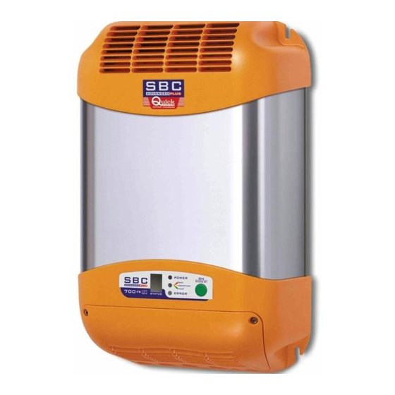
SBC ADVANCED PLUS
M
EDIUM
SBC 300 ADV PLUS FR
SBC 500 ADV PLUS FR
SBC 700 ADV PLUS FR
SBC 650 ADV PLUS FR
Manuale d'uso
I
User's Manual
GB
Manuel de l'utilisateur
F
Benutzerhandbuch
D
Manual del usuario
E
P
OWER
CARICABATTERIA SBC ADVANCED PLUS
SBC ADVANCED BATTERY CHARGER PLUS
CHARGEUR DE BATTERIE SBC ADVANCED PLUS
BATTERIELADEGERÄT SBC ADVANCED PLUS
CARGADOR DE BATERIAS SBC ADVANCED PLUS
REV 002

Werbung

Inhaltsverzeichnis
loading

Inhaltszusammenfassung für Quick SBC 700 ADV PLUS FR

  • Seite 1 SBC ADVANCED PLUS EDIUM OWER SBC 300 ADV PLUS FR SBC 500 ADV PLUS FR SBC 700 ADV PLUS FR SBC 650 ADV PLUS FR Manuale d’uso CARICABATTERIA SBC ADVANCED PLUS User’s Manual SBC ADVANCED BATTERY CHARGER PLUS Manuel de l’utilisateur...
  • Seite 3 INDICE Pag. 4-5 Caratteristiche e Installazione Pag. 9 Funzionamento: Caratteristiche di Pag. 6 Installazione: Alimentazione dell’appa- carica recchio,Batterie, Pag. 10 Funzionamento: Pannello di controllo Pag. 7 Funzionamento: Selezione della moda- Pag. 11-12 Segnalazioni lità di carica Pag. 13-14 Programmazione caricabatterie Pag.
  • Seite 4: Caratteristiche E Installazione

    QUICK™. I CARICABATTERIE SONO STATI PROGETTATI PER INSTALLAZIONI FISSE (USO INTERNO). I caricabatterie Quick™ sono stati progettati e realizzati per gli scopi descritti in questo manuale d’uso. La società Quick™ non si assume alcuna responsabilità per danni diretti o indiretti causati da un uso improprio dell’apparecchio, da un’errata installazione o da possibili errori presenti in questo manuale.
  • Seite 5: Ambiente Di Installazione

    A seconda del modello utilizzare le batterie e i cavi sui terminali di uscita specificati nella seguente tabella: MODELLO SBC 300 ADV PLUS FR SBC 500 ADV PLUS FR SBC 700 ADV PLUS FR SBC 650 ADV PLUS FR Tensione batterie 12 V 24 V Capacità batterie 140 ÷...
  • Seite 6 AC e dalle batterie. ATTENZIONE: nel caso in cui il cavo di alimentazione sia danneggiato, farlo sostituire da un centro assistenza Quick™. Per evitare incidenti l’apparecchio deve essere aperto so- lo da personale autorizzato.
  • Seite 7 FUNZIONAMENTO Il polo positivo della batteria o del gruppo batterie deve essere collegato a uno dei terminali positivi del caricabatterie; il polo negativo della batteria o del gruppo batterie al terminale negativo del caricabatterie. Per effettuare i collegamenti utilizzare i capicorda forniti in dotazione con l’apparecchio.
  • Seite 8 FUNZIONAMENTO Di seguito si riporta la posizione e la descrizione dei segnali presenti sul connettore: CONNETTORE A VASCHETTA DB9 Descrizione Terminatore CAN BUS (124 ohm) Interfaccia CAN BUS - Segnale CANL Negativo caricabatteria Riservato Terra Riservato Interfaccia CAN BUS - Segnale CANH Stato semplificato del caricabatteria (+V uscita, 20mA max) +5Vdc (10mA max) STATO SEMPLIFICATO CARICABATTERIE...
  • Seite 9: Caratteristiche Di Carica

    FUNZIONAMENTO FUNZIONAMENTO All’accensione del caricabatterie, per un breve istante di tempo, si illumineranno tutti i led presen- ti sul pannello frontale. Dopodichè il caricabatterie si porrà nello stato di carica richiesto dalle bat- terie (o dal carico) collegate. Il caricabatterie è dotato di una caratteristica di carica del tipo IUoU. I caricabatterie SBC possono essere utilizzati anche come alimentatori, cioè...
  • Seite 10 FUNZIONAMENTO PANNELLO DI CONTROLLO Il pannello di controllo è composto da tre LED, una cifra a 7 segmenti ed un pulsante: LED POWER, LED FASE DI CARICA (BULK, ABSORPTION, FLOAT), LED ERROR, cifra STATUS e pulsante ON/STAND-BY (vedi fig. 4). FIG.4 Pulsante ON/STAND BY: Tramite questo pulsante è...
  • Seite 11 SEGNALAZIONI SEGNALAZIONI E’ attiva la modalità di metà potenza tramite comando manuale. [ Simbolo lampeggiante ]. E’ attiva la modalità di monitor. PROBLEMI CON RESET AUTOMATICO La tensione di rete AC è troppo bassa. Il caricabatteria si porta in modalità di metà potenza.
  • Seite 12 Problema di comunicazione grave su CAN BUS. Verificare i cablaggi della rete CAN e il corretto inserimento dei terminatori. I PROBLEMI E2/E3 RICHIEDONO UNA VERIFICA DA PARTE DI UN CENTRO ASSISTENZA QUICK™. Per eliminare i problemi con reset manuale bisogna rimuovere la causa che li ha generati, spegnere il...
  • Seite 13 PROGRAMMAZIONE CARICABATTERIE PROGRAMMAZIONE CARICABATTERIE Le funzioni programmabili del caricabatterie sono le seguenti: • Selezione della modalità di carica per batterie elettrolita liquido o gel. • Selezione del gruppo di rete di appartenenza. • Selezione della priorità all’interno del gruppo di rete. •...
  • Seite 14 PROGRAMMAZIONE CARICABATTERIE I dispositivi appartenenti ad un gruppo “ ”, “ ” o “ ” possono colloquiare solamente tra loro. Fa eccezione il gruppo “ ” (universale) che può colloquiare con qualsiasi dispositivo. La distinzione tra gruppi differenti è indispensabile per poter collegare tutti i dispositivi alla stessa rete CAN anche se appartengono ad impianti elettrici differenti.
  • Seite 15: Manutenzione - Dati Tecnici

    La protezione puo essere inefficace in alcune condizioni operative. Doppio controllo software/hardware. Cycoloy ® è un marchio registrato dalla GE Plastics. LA QUICK™ SI RISERVA IL DIRITTO DI APPORTARE MODIFICHE ALLE CARATTERISTICHE TECNICHE DELL’APPARECCHIO E AL CONTENUTO DI QUESTO MANUALE SENZA ALCUN PREAVVISO.
  • Seite 16: The Package Contains

    OF DOUBT CONTACT THE “QUICK™” SUPPLIER OR AFTER SALES SERVICE DEPARTMENT. THE BATTERY CHARGERS ARE DESIGNED FOR FIXED INTERNAL INSTALLATIONS ONLY. “Quick™” battery chargers have been designed and made for the reasons described in this user’s manual. The “Quick™” Company does not accept any responsibility for direct or indirect damage caused by improper use of the equipment, bad installation or by possible errors occur- ring in this manual.
  • Seite 17: Installation Site

    Depending upon model, use the batteries and cables on the output terminals as specified in the following table: MODEL SBC 300 ADV PLUS FR SBC 500 ADV PLUS FR SBC 700 ADV PLUS FR SBC 650 ADV PLUS FR Battery voltage 12 V...
  • Seite 18 AC mains and the batteries. WARNING: in cases where the power supply cable could be damaged, have this changed by a “Quick™” service centre. In order to avoid accidents, the equipment must only be opened by authorised personnel. FIG.2...
  • Seite 19: Control Signals

    INSTALLATION The positive terminal of the battery or of the group of batteries must be connected to one of the positive terminals of the battery charger. The negative terminal of the battery or of the group of batteries must be connected to the negative terminal of the battery charger. To make the con- nections use the cable terminals supplied with the equipment.
  • Seite 20: Operating

    OPERATING I GB The position and description of the signals on the connector are listed below: FEMALE CONNECTOR (DB 9) Description CAN BUS terminator (124 ohm) CANL signal - CAN BUS interface Battery charger negative Not used Earth Not used CANH signal - CAN BUS interface Basic state of the battery charger (+V output, 20mA max) +5Vdc (10 mA max)
  • Seite 21: Charging Characteristics

    OPERATING I GB OPERATION When the battery charger is switched on for a short period, all the LEDS on the front panel will light up. After that the battery charger will place itself in the optimum charging mode to best suit the batteries or load connected.
  • Seite 22: Control Panel

    OPERATING CONTROL PANEL The control panel is made-up of three LED, a 7 segment display and a button: POWER LED, CHARGE PHASE LED (BULK, ABSORPTION, FLOAT) ERROR LED, STATUS display and ON/STAND-BY button (see fig.4). FIG.4 ON/STAND-BY BUTTON: Use this button to put the battery charger in stand-by mode. To activate this mode simply press the button quickly (press and release in less than one second).
  • Seite 23 NOTIFICATION SIGNS NOTIFICATION SIGNS The half-power mode has been activated by the manual control. [ Flashing symbol ]. Monitor mode is activeted. PROBLEMS WITH AUTOMATIC RESET The AC mains voltage is too low. The battery charger goes into half-power mode. The message disappears when the mains voltage falls within the nominal range again.
  • Seite 24 Serious CAN BUS communication problem. Check the CAN network wiring and make sure the terminals have been installed properly. THE E2/E3 PROBLEMS NEED TO BE CHECKED BY A “QUICK™” SERVICE CENTRE. In order to eliminate the problems with manual reset you must remove the cause of the problem,...
  • Seite 25 PROGRAMMING THE BATTERY CHARGER PROGRAMMING THE BATTERY CHARGER The battery charger has the following programmable functions: • Selecting the battery charge mode - liquid or gel electrolite. • Selecting the network group. • Selecting the priority within the network group. •...
  • Seite 26 BATTERY CHARGER PROGRAMMING The devices belonging to one group “ ”, “ ” or “ ” can only dialog between themselves. Group “ ” (Universal) is an exception as this can dialog with any other device. The distinction between different groups is very important in order to connect all the devices to the same CAN network even if they belong to different electrical systems.
  • Seite 27: Maintenance - Technical Data

    Protection may be inefficient in some operative conditions. Software/hardware double-check. Cycoloy ® is a registered trade mark of GE Plastics. QUICK™ RESERVES THE RIGHT TO MODIFY THE TECHNICAL CHARACTERISTICS OF THE EQUIPMENT AND THE CONTENTS OF THIS MANUAL WITHOUT PRIOR NOTICE.
  • Seite 28: Caractéristiques Et Installation

    LES CHARGEURS DE BATTERIES SBC ONT ÉTÉ CONÇUS POUR DES INSTALLATIONS FIXES (USAGE INTÉRIEUR). Les chargeurs de batterie Quick™ ont été conçus et réalisés pour répondre aux besoins dé- crits dans ce manuel d'utilisation. La société Quick™ ne prend aucune responsabilité pour les dommages directs ou indirects causés par une utilisation impropre de l'appareil, par une mau-...
  • Seite 29: Lieu D'installation

    Suivant le modèle, utiliser les batteries et les câbles (sur les bornes de sortie) qui sont spécifiés dans le tableau suivant: MODÈLE SBC 300 ADV PLUS FR SBC 500 ADV PLUS FR SBC 700 ADV PLUS FR SBC 650 ADV PLUS FR Tension des batteries 12 V 24 V Capacité...
  • Seite 30: Alimentation De L'appareil

    ATTENTION: si le câble d’alimentation est abîmé, le faire remplacer par un centre de maintenance Quick™. Pour éviter tout accident, il est nécessaire que l’appareil soit ou- vert uniquement par un personnel autorisé. L’ouverture du chargeur de batteries de la part d’un personnel non autorisé...
  • Seite 31 INSTALLATION Le pôle positif de la batterie ou du groupe batterie doit être connecté à la borne positive du chargeur; le pôle négatif de la batterie ou du groupe batterie doit être connecté à la borne né- gative du chargeur. Pour effectuer les connexions, utiliser les cosses qui sont fournies avec l’appareil.
  • Seite 32 FONCTIONNEMENT Tableau d’affectation des pinset description des signaux présents sur le connecteur: CONNECTEUR À BROCHE DB9 Description Terminaison CAN BUS (124 ohm) Interface CAN BUS – Signal CANL Négatif chargeur de batterie Réservé Terre Réservé Interface CAN BUS – Signal CANH Etat simplifié...
  • Seite 33 INSTALLAZIONE FONCTIONNEMENT A l’allumage du chargeur de batterie, pendant un court moment, toutes les Led’s présentes sur le ta- bleau en façade s'allument. Le chargeur de batteries se met ensuite dans la condition de charge requi- se par les batteries connectées (ou par la charge). Le chargeur possède une caractéristique de charge du type IUoU.
  • Seite 34 FONCTIONNEMENT TABLEAU DE CONTRÔLE Le tableau de contrôle se compose de trois LED, un display à 7 segments et un touche: LED POWER, LED PHASE DE CHARGE (BULK, ABSORPTION, FLOAT), LED ERROR, STATUS display et touche ON/STAND-BY (voir fig. 4). FIG.4 Touche ON/STAND BY (veille): A l’aide de cette touche, il est possible de mettre le chargeur de batterie en stand-by (veille).
  • Seite 35 SIGNALISATIONS SIGNALISATIONS Le mode demi puissance est activé au moyen de la commande manuelle. [ Symbole clignotant ]. Le mode moniteur est activé. PROBLÈME AVEC LE CONTRÔLE AUTOMATIQUE La tension de secteur AC est trop basse. Le chargeur de la batterie se met en mode demi-puissance.
  • Seite 36 Problème de communication grave sur CAN BUS. Vérifier les câblages du ré- seau CAN et la correcte connexion des terminaisons. LES PROBLÈMES E2/E3 NÉCESSITENT D'ÊTRE VÉRIFIÉS PAR UN CENTRE D'ASSISTANCE QUICK™. Pour résoudre les problèmes, il faut éliminer la cause qui les a provoqués. Eteindre le chargeur...
  • Seite 37 PROGRAMMATION CHARGEUR DE BATTERIE PROGRAMMATION CHARGEUR DE BATTERIE Les fonctions programmables du chargeur de batterie sont les suivantes: • Sélection du mode de charge pour batterie électrolyte liquide ou gel. • Sélection d’un groupe du réseau. • Sélection de la priorité au sein d'un groupe du réseau. •...
  • Seite 38 PROGRAMMATION CHARGEUR DE BATTERIE Les appareils appartenant à un groupe “ ”, “ ” ou “ ” peuvent uniquement communiquer en- tre eux. A l'exception du groupe “ ” (universel) qui peut communiquer avec tout autre appareil. La distinction entre groupes différents est indispensable afin de pouvoir relier tous les appareils au même réseau CAN même s'ils appartiennent à...
  • Seite 39: Entretien - Caractéristiques Techniques

    La protection peut être inefficace dans certaines conditions de fonctionnement. Double contrôle logiciel/matériel. Cycoloy ® est une marque protégée de la GE Plastics LA SOCIETÉ QUICK™ SE RÉSERVE LE DROIT D’APPORTER LES MODIFICATIONS NÉCESSAIRES AUX CARACTÉRISTIQUES TECHNIQUES DE L’APPAREIL ET AU CONTENU DE CE LIVRET SANS AVIS PRÉALABLE.
  • Seite 40: Eigenschaften Und Installation

    DIE LADEGERÄTE SBC WURDEN FÜR FESTE INSTALLATION ENTWICKELT (GEBRAUCH IM INNENBEREICH). Die Quick™-Ladegeräte wurden für die in dieser Gebrauchsanleitung beschriebenen Zwecke ent- worfen und hergestellt. Die Gesellschaft Quick™ übernimmt keinerlei Verantwortung für direkte oder indirekte Schäden, die durch einen unsachgemäßen Gebrauch des Geräts, durch eine falsche Installation oder durch mögliche, in diesem Handbuch enthaltene Fehler entstanden sind.
  • Seite 41: Erforderliche Ausstattung Für Die Installation

    Je nach Modell die in der folgenden Tabelle angegebenen Batterien und Kabel (an den Aus- gangsklemmen) verwenden: MODELL SBC 300 ADV PLUS FR SBC 500 ADV PLUS FR SBC 700 ADV PLUS FR SBC 650 ADV PLUS FR Batteriespannung 12 V 24 V Batterieleistung 140 ÷...
  • Seite 42: Versorgungsspannung

    Gerät vom Wechselstromnetz und von der Batterie getrennt ist. ACHTUNG: Bei Beschädigung des Stromversorgungskabels dieses von einem Quick Kundendienstzentrum auswechseln lassen. Zur Verhinderung von Unfällen darf das Gerät ausschließlich von autorisiertem Personal geöffnet werden. Das Öffnen des Lade- geräts durch nicht autorisiertes Personal führt zum Verfall der Garantie.
  • Seite 43: Steuersignale

    INSTALLATION Der positive Pol der Batterie oder der Batteriegruppe muss an einer der positiven Klemmen des Ladegeräts angeschlossen werden. Der negative Pol der Batterie oder der Batteriegruppe muss am negativen Pol des Ladegeräts angeschlossen werden. Zur Ausführung der Anschlüs- se, den zusammen mit dem Gerät gelieferten Kabelschuh verwenden. Wenn lediglich eine Batteriegruppe oder zwei angeschlossen werden, muss stets der mit “MA- STER”...
  • Seite 44: Betrieb

    BETRIEB Es folgt eine Beschreibung der am Verbinder vorliegenden Signale: VERBINDER DB9 Beschreibung CAN-BUS-Anschluss (124 Ohm) Schnittstelle CAN BUS - Signal CANL Negativ - Batterieladegerät Nicht benutzt Erde Nicht benutzt Schnittstelle CAN-BUS – Signal CANH Zustand des Batterieladegeräts (+V Ausgabe, max. 20mA) +5Vdc (max.
  • Seite 45: Modalität Mit Halber Leistung

    BETRIEB BETRIEB Bei Einschalten des Ladegeräts leuchten für einen kurzen Moment alle an der vorderen Tafel vorhanden Leuchtdioden auf. Nachdem sie alle Verkabelungen durchgeführt haben, das Gerät an Spannung legen. Es leuchten für einen kurzen Augenblick alle an der Vordertafel vorhande- nen Leuchtanzeigen auf.
  • Seite 46 BETRIEB BEDIENUNGS DISPLAY Die Steuertafel besteht aus drei Leuchtdioden, 7 stellige Segment Anzeige und taste: LED POWER, LED LADUNG PHASE (BULK, ABSORPTION, FLOAT), LED FEHLER, STATUS anzeige und taste ON/STAND-BY (siehe Abb 4). FIG.4 Taste ON/STAND-BY: Anhand dieser Taste kann das Batterieladegerät in den Standby-Zustand versetzt werden. Um die Standby-Modalität zu aktivieren, muss die Taste schnell gedrückt werden (das Drücken und Loslassen muss in weniger als einer Sekunde erfolgen).
  • Seite 47: Probleme Bei Automatischer Rückstellung

    MELDUNGEN MELDUNGEN Die Betriebsweise mit halber Leistung ist über manuelle Steuerung aktiviert. [ blinkendes Symbol ]. Der Monitor-Modus ist aktiviert. PROBLEME BEI AUTOMATISCHER RÜCKSTELLUNG Die Wechselstrom-Netzspannung ist zu niedrig. Das Batterieladegerät stellt sich auf die Betriebsweise mit halber Leistung ein. Diese Meldung verschwindet, sobald die Netz- spannung wieder innerhalb des Nennbereichs liegt.
  • Seite 48: Probleme Bei Manueller Rückstellung

    Blinkmodus ab. Schweres Kommunikationsproblem bei CAN BUS. Die Verkabe- lung des CAN-Netzwerks sowie den korrekten Anschluss der Klemmen überprüfen. DIE PROBLEME E2/E3 ERFORDERN EINE KONTROLLE SEITENS EINES QUICK™-KUNDENDIENSTSERVICES. Zur Beseitigung der Probleme muss die Ursache, die zum Auftreten des Problems geführt hat, beseitigt...
  • Seite 49: Aktivierung Der Programmierung

    PROGRAMMIERUNG BATTERIELADEGERÄT PROGRAMMIERUNG BATTERIELADEGERÄT Die programmierbaren Funktionen des Batterieladegerätes lauten wie folgt: • Wahl der Lademöglichkeit für Flüssig- oder Gel-Elektrolytbatterien. • Wahl der zugehörigen Netzwerkgruppe. • Wahl der Vorrangigkeit innerhalb der Netzgruppe. • Aktivierung/Deaktivierung des Monitor-Modus’. Aktivierung der Programmierung Zum Aktivieren des Programmierverfahrens muss die auf der Steuertafel befindliche Taste 6 Sekunden lang gedrückt werden.
  • Seite 50: Programmierung Batterieladegerät

    PROGRAMMIERUNG BATTERIELADEGERÄT Die Vorrichtungen, die einer Gruppe “ ”, “ ” oder “ ” angehören, können nur untereinander kommunizieren. Die Gruppe “ ” (universell) bildet hier eine Ausnahme, da sie mit jeder beliebi- gen Vorrichtung kommunizieren kann. Das Unterscheiden zwischen verschiedenen Gruppen ist unerlässlich, damit alle Vorrichtungen an das gleiche CAN-Netzwerk angeschlossen werden können, auch wenn sie unterschiedlichen elektrischen Anlagen angehören.
  • Seite 51: Wartung - Technische Daten

    Die Schutzeinrichtung kann sich bei bestimmten Betriebsumständen als unwirksam erweisen. Doppelkontrolle Software/Hardware. Cycoloy ® ist ein von GE Plastics eingetragenes Warenzeichen. QUICK™ BEHÄLT SICH DAS RECHT AUF ÄNDERUNGEN DER TECHNISCHEN EIGENSCHAFTEN DES GERÄTS UND DES INHALTS DIESES HANDBUCHS OHNE VORANKÜNDIGUNG VOR.
  • Seite 52 Los cargadores de baterías Quick™ han sido proyectados y realizados para los objetivos descritos en este manual de uso. La sociedad Quick™ no asume responsabilidad alguna por daños directos o indirectos causados por un uso inadecuado del equipo, por una errónea instalación o por posibles errores presentes en este manual.
  • Seite 53 En base al modelo que se utilize, las baterías y los cables (en los terminales de salida) que se indican en la siguiente tabla: MODELO SBC 300 ADV PLUS FR SBC 500 ADV PLUS FR SBC 700 ADV PLUS FR SBC 650 ADV PLUS FR Tensión baterías 12 V 24 V Capacidad baterías 140 ÷...
  • Seite 54: Alimentación Del Aparato

    AC y de las baterías. ATENCIÓN: en caso de que el cable de alimentación esté dañado, hacerlo sustituir por un centro de asistencia Quick™. Para evitar accidentes, el aparato debe ser abierto solamente por el personal autorizado. FIG.2...
  • Seite 55: Señales De Control

    INSTALACIÓN El polo positivo de la batería o del grupo baterías debe estar conectado a uno de los termina- les positivos del cargador de baterías; el polo negativo de la batería o del grupo baterías al ter- minal negativo del cargador de baterías. Para efectuar las conexiones utilizar los terminales de cables suministrados con el equipo.
  • Seite 56 FUNCIONAMIENTO A continuación se indica la posición y la descripción de las señales presentes en el conector: CONECTOR DB9 Descripción Terminador CAN BUS (124 ohm) Intercara CAN BUS – Señal CANL Negativo cargador de baterías Reservato Tierra Reservato Intercara CAN BUS – Señal CANH Estato simplificado del cargador de baterías (+V salida, 20mA max) +5Vdc (10mA max) ESTADO SIMPLIFICADO CARGADOR DE BATERÍAS...
  • Seite 57 FUNCIONAMIENTO FUNCIONAMIENTO Al encender el cargador de baterías, durante un breve instante de tiempo, se iluminarán todos los leds presentes en el panel frontal. Sucesivamente, el cargador de baterías se colocará en el estado de carga requerido por las baterías (o por la carga) conectadas. El cargador de baterías consta de una característica de carga del tipo IUoU.
  • Seite 58: Tablero De Control

    FUNCIONAMIENTO TABLERO DE CONTROL El panel de control está compuesto por tres LED, una cifra a 7 segmentos y un pulsador: LED POWER, LED FASE DE CARGA (BULK, ABSORPTION, FLOAT), LED ERROR, cifra STATUS e pulsador ON/STAND-BY (ver fig. 4). FIG.4 Pulsador ON/STAND-BY: Mediante éste pulsador es posible poner en stand-by el cargador de baterías.
  • Seite 59 SEÑALACIONES SEÑALACIONES Es activa la modalidad de mitad de potencia mediante comando manual. [ símbolo intermitente ]. Es activa la modalidad de monitor. PROBLEMAS CON RESET AUTOMATICO La tensión de red AC es muy baja. El cargador de baterías se lleva en modalidad de mitad de potencia.
  • Seite 60 CAN y la correcta inserción de los terminadores. LOS PROBLEMAS E2/E3 REQUIEREN UNA VERIFICACIÓN POR PARTE DE UN CENTRO DE ASISTENCIA QUICK™. Para eliminar los problemas con reset manual es necesario eliminar la causa que los ha provocado, apa-...
  • Seite 61 PROGRAMACION CARGADOR DE BATERIAS PROGRAMACION CARGADOR DE BATERIAS Las funciones programables del cargador de baterías son las siguientes: • Selección de la modalidad de carga para baterías electrólito líquido o gel. • Selección del grupo de red de pertenencia. • Selección de la prioridad al interno del grupo de red. •...
  • Seite 62 PROGRAMACION CARGADOR DE BATERIAS Los dispositivos que pertenecen a un grupo “ ”, “ ” o “ ” pueden coloquiar solamente entre ellos. Hace excepción el grupo “ ” (universal) que puede coloquiar con cualquier dispositivo. La distinción entre grupos diferentes es indispensable para poder conectar los dispositivos a la misma red CAN aunque si pertenecen a instalaciones electricas diferentes.
  • Seite 63: Especificaciones Tecnicas

    La protección puede ser ineficaz en algunas condiciones operativas. Doble control software/hardware. Cycoloy ® es una marca registrada de GE Plastics QUICK™ SE RESERVA EL DERECHO DE APORTAR MODIFICACIONES EN LAS CARACTERÍSTICAS TÉCNICAS DEL APARATO Y EN EL CONTENIDO DE ESTE MANUAL SIN OBLIGACIÓN DE AVISAR PREVIAMENTE.
  • Seite 64 SBC ADVANCED PLUS - DIMENSIONI (mm) DIMENSIONS - DIMENSIONS - ABMESSUNGEN - MEDIDAS 300 ADV PLUS / 500 ADV PLUS...
  • Seite 65 SBC ADVANCED PLUS - DIMENSIONI (mm) DIMENSIONS - DIMENSIONS - ABMESSUNGEN - MEDIDAS 700 ADV PLUS / 650 ADV PLUS...
  • Seite 66 NOTE NOTES - NOTES - DIE ANMERKUNGEN - NOTAS...
  • Seite 67 NOTE NOTES - NOTES - DIE ANMERKUNGEN - NOTAS...
  • Seite 68 CMSBCAPMER02 QUICK™ - VIA PIANGIPANE , 120/A - 48020 PIANGIPANE (RAVENNA) - ITALY TEL. +39.0544.415061 - FAX +39.0544.415047 www.quickitaly.com - E-mail: quick@quickitaly.com...

Inhaltsverzeichnis