Herunterladen Inhalt Inhalt Diese Seite drucken

Werbung

Verfügbare Sprachen
  • DE

Verfügbare Sprachen

  • DEUTSCH, seite 40
Cod.73302740
Ver.: A4
Manuale di istruzioni
Instructions manual
Manuel d'instructions
Bedienungsanleitung
Manual instrucciones
S100E
S120E
S125E
Forno elettrico
Electric oven
Four electrique
Elektrische Ofen
Horno Electrico
Numeri di matricola / Serial numbers :

Werbung

Inhaltsverzeichnis
loading

Inhaltszusammenfassung für Moretti Forni evolution S-Serie

  • Seite 1 Manuale di istruzioni Instructions manual Manuel d’instructions Bedienungsanleitung Manual instrucciones S100E S120E S125E Forno elettrico Electric oven Four electrique Elektrische Ofen Horno Electrico Numeri di matricola / Serial numbers : Cod.73302740 Ver.: A4...
  • Seite 2 - m a i l : i n f o @ m o r e t t i f o r n i . c o m DICHIARAZIONE DI CONFORMITA’ DECLARATION OF CONFORMITY MORETTI FORNI S.P.A. Il costruttore /The manufacturer Indirizzo del costruttore/ Manufacturer address: Via A. MEUCCI N. 4...
  • Seite 3 We declare under sole responsability that the products to which this declaration relates is in conformity with the following standards <> following the provisions of the directives<>.
  • Seite 4 INDICE SPECIFICHE TECNICHE INSTALLAZIONE FUNZIONAMENTO MANUTENZIONE ORDINARIA MANUTENZIONE STRAORDINARIA CATALOGHI RICAMBI Nota: Il presente manuale é predisposto per la lettura in cinque lingue. Istruzioni originali in Italiano e traduzioni delle istruziuoni originali in Inglese, Francese, Tedesco e Spagnolo. Per una miglior chiarezza e lettura,il presente manuale, potrebbe essere fornito in più parti separate e può essere spedito via mail contattando la Ditta Costruttrice.
  • Seite 5: Specifiche Tecniche

    SPECIFICHE TECNICHE NOTA: Solo per camere di cottura provviste di vaporiera. DESCRIZIONE DELLE APPARECCHIATURE L’apparecchiatura è costituita da più moduli sovrapposti: - Cappa - Camera/e di cottura - Base - Supporto o cella di lievitazione Ogni modulo camera di cottura è totalmente indipendente, ha la regolazione della temperatura di tipo elettronico, è...
  • Seite 6: Collegamento Elettrico

    Per effettuare il collegamento elettrico, rimuovere il coperchio di NOTA: nel caso di composizione con anello distanziatore protezione posizionato sul lato posteriore della camera di cottura (possibile solo con cella) procedere come segue: (fig.8). Il cavo di collegamento deve essere fornito dall'installatore. - rimuovere le ruote dalla cella e rimontarle al di sotto dell’anello Per il collegamento alla rete elettrica è...
  • Seite 7: Messa In Funzione Camera Di Cottura

    l’interruttore generale 0/1 su tutti i moduli camera di cottura (fig. 1 NOTA: Il dispositivo scelto dovrebbe trovarsi nelle immediate part. A). vicinanze dell’apparecchio ed essere posizionato in luogo Sul montante anteriore destro di ogni camera di cottura è posto il facilmente accessibile.
  • Seite 8: Prima Accensione

    3.2.1 PRIMA ACCENSIONE La regolazione della temperatura della camera di cottura è fissata per Per la prima accensione dell’attrezzatura e per le successive accensioni una temperatura massima di 450°C (850°F) per la pizzeria e 270°C dopo un periodo prolungato di inattività è indispensabile rispettare la (520°F) per la pasticceria.
  • Seite 9: Messa In Funzione Camera Di Cottura: Modalita' Dual-Temp

    • originale, infatti, non vengono cambiati. Per modificare i parametri di FUNZIONE “ECO STAND-BY” un programma seguire le istruzioni del paragrafo 3.3. La funzione “Stand By” permette di mantenere il forno caldo riducendo Nel caso di utilizzo di un programma costituito da più fasi di cottura il consumo di energia elettrica, soluzione ideale nelle fasi di pausa attivare la prima fase del programma azionando il TIMER 1 (vedere momentanea delle operazioni di cottura.
  • Seite 10 dispone di uno spettro di potenze virtualmente infinito, tra le quali platea fase 1”) (fig. 20d). Effettuare la modifica dei parametri con i tasti viene scelta, istante per istante, la più ottimale. “+” e “-” corrispondenti poi confermare con il tasto “OK”. Per attivare le resistenze e quindi dare avvio alla fase di riscaldamento La programmazione prosegue con le schermate riguardanti la della camera di cottura premere il tasto “START”.
  • Seite 11 visualizza il numero di programmi correttamente copiati dal memoria 3.5.2 PULIZIA del forno al dispositivo USB. Togliere il dispositivo USB e La funzione “Pulizia forno” consente di eliminare i residui di cottura riposizionare il tappo precedentemente rimosso. presenti sulle pareti interne della camera del forno tramite riduzione pirolitica (carbonizzazione).
  • Seite 12: Impostazione Data/Ora

    “Aggiorna software”: avvia procedura per l’aggiornamento del NOTA: Una impostazione “On” che non preveda una software conseguente impostazione “Off” è comunque attiva: il forno si ATTENZIONE! Procedura riservata solo a personale accenderà automaticamente all’orario programmato e andrà spento manualmente. Allo stesso modo una impostazione “Off” che formato ed autorizzato dalla Casa Costruttrice.
  • Seite 13: Messa In Funzione Cappa Aspirante

    Allarme Avaria Termocoppia (questo allarme indica anche a) tenere premuto il tasto STOP per alcuni secondi. Il display mostra di quale termocoppie si tratta) (fig. 22) una schermata di spegnimento. Attendere che il display si spenga. Allarme Errore Comunicazione b) spegnere gli interruttori generali della camera (fig. 1 part. A), della Allarme Sovratempertura Quadro elettrico cella (fig.
  • Seite 14: Pulizia Generale

    ATTENZIONE ISTRUZIONI SEGUENTI RELATIVE ALLA “MANUTENZIONE STRAORDINARIA” SONO STRETTAMENTE RISERVATE PERSONALE TECNICO SPECIALIZZATO MUNITO DI REGOLARE LICENZA, RICONOSCIUTO ED ABILITATO DALLA DITTA COSTRUTTRICE. MANUTENZIONE STRAORDINARIA 5.3.2 SOSTITUZIONE SCHEDA CON LCD Eseguite le operazioni al punto 5.1, per la sostituzione del pirometro OPERAZIONI PRELIMINARI DI SICUREZZA digitale di cottura procedere nel seguente modo: - togliere il pannello laterale destro (part.6 tav.A) svitando le quattro...
  • Seite 15 - togliere il pannello laterale destro (part.6 tav.A) svitando le quattro SOSTITUZIONE PARTI CELLA DI LIEVITAZIONE viti di fissaggio; CON UIDIFCATORE - scollegare i faston del termostato; - togliere il sensore del termostato, posto all'interno della lana di 5.5.1 SOSTITUZIONE RESISTENZA DELLA VASCHETTA roccia isolante, rimuovendo con una lama la parte di lana di roccia Eseguite le operazioni al punto 5.1, per la sostituzione della resistenza interessata;...
  • Seite 16 INDEX TECHNICAL DATA INSTALLATION OPERATION ORDINARY MAINTENANCE SPECIAL MAINTENANCE LIST OF SPARE PARTS Note: This manual is printed in five different languages. Original instructions in Italian and translations of the original instructions in English, French, German and Spanish. For better clarity and reading this manual, it could be provided in several separate parts and can be sent by mail by contacting the Manufacturer. WARRANTY Standards and rules Warranty only covers the replacement free to factory of pieces eventually broken or damaged because of faulty materials or manufacture.
  • Seite 17: Technical Data

    TECHNICAL DATA NOTE: Only for baking chambers fitted with steamer. DESCRIPTION OF THE OVEN The oven comprises several units positioned one on top of the other: - hood - baking chamber/s - base - Support or leavening compartment Each baking chamber is totally independent and is equipped with electronic temperature regulator, safety thermostat and with a single WARNING! To avoid scalding, do not use loaded containers...
  • Seite 18: Electrical Connection

    reference feet of each unit into the housing on the one underneath it When connecting to the power mains, it is necessary to fit a plug that (item A - fig.5). complies with the standards and regulations in force. Insert a cable with an adequate cross-section (see technical data) into NOTE: In case of structures with spacer ring (possible only the cable raceway provided (fig.9 part B) and connect it to the terminal...
  • Seite 19: Switching On For The First Time

    When connection has been completed, check that the supply voltage, 7) Power Booster function enable/disable (“Booster”) with the appliance running, does not differ from the rated value by 8) Access to settings menu (“Menu”) more than ±10%. 9) Custom function (“Hotkey”) The user interface has the following viewing areas (fig 16): WARNING! It is essential that the appliance be properly...
  • Seite 20: Switching On In Program Mode

    - Increase the temperature to 270°C (520°F) and leave the chamber graphic display also provides information on the power level employed by the heating elements at any time, shown by how much of the “bolt” operating for about 1 hour. If there is a great deal of steam inside the chamber, open the door for a few minutes to let out the steam and itself is lit up.
  • Seite 21 To enable the timer T1 and start the countdown, press T1. The timer “standby” and not usable for baking. status passes from “STOP” to “PLAY” and the countdown is enabled. To enable/disable the function, press “MENU”, select “HALF LOAD” Pressing T1 again sets the timer to “PAUSE”, a useful function if the with the “SELECTION”...
  • Seite 22 • • USB EXPORT INSERT NEW Insert the USB device into the slot on the right side of the appliance The first screen for the program insert procedure required the name of after removing the plug. The display will show a list of the directories in the program to be entered (fig.
  • Seite 23: Setting The Time/Date

    for a factory set period of time. When the program has completed and made, one week later at the same time, the oven will start up (or shut the oven is again at room temperature, it is sufficient to remove the down) again.
  • Seite 24: Ordinary Maintenance

    “Sensitivity”: a function that makes it possible to adjust oven To switch off the leavening compartment, set the thermostat sensitivity to changes in temperature, electronically. Three (fig.24 Item 2) to zero. settings are available (from least to most sensitive): “Low”, WARNING! Do not touch the heating elements;...
  • Seite 25: Periods Of Inactivity

    could damage surfaces. Before starting up the appliance again, make sure that none of the cleaning equipment has been left inside. PERIODS OF INACTIVITY If the appliance is not to be used for long periods: - Disconnect it from the power supply. - Cover it to protect it from dust.
  • Seite 26: General Cleaning

    WARNING FOLLOWING INSTRUCTIONS, WHICH CONCERN “SPECIAL MAINTENANCE” ARE STRICTLY RESERVED TO SPECIALIST TECHNICIANS WITH THE RELEVANT LICENSE AS WELL AS BEING APPROVED BY THE MANUFACTURER. SPECIAL MAINTENANCE - loosen the nuts on the top and bottom clamps, tightening the LCD board;...
  • Seite 27 - replace the thermostat (item 28, plate A) and the respective sensor, - remove the heating element (item 14 tab.B); along with any worn rock wool insulation, if necessary; - disconnect the power wires from the heating element; - perform the above operations in reverse order to reassemble. - perform the steps in reverse order to refit the new heating element.
  • Seite 28: Inhaltsverzeichnis

    TABLE DES MATIÈRES SPECIFICATIONS TECHNIQUES INSTALLATION FONCTIONNEMENT ENTRETIEN ORDINAIRE ENTRETIEN EXTRAORDINAIRE LISTE DES PIECES DE RECHANGE Remarque: Ce manuel a été rédigé pour la lecture en cinq langues. Instructions originales en italien et traduction des instructions en Anglais, Français, Allemand et Espagnol.
  • Seite 29: Specifications Techniques

    SPECIFICATIONS TECHNIQUES REMARQUE: Seulement pour les chambres de cuisson munies d’un moyen d’évacuation de vapeur. DESCRIPTION DU FOUR Le four est constitué de plusieurs modules superposés : - Hotte - Chambre/s de cuisson - Soubassement - Support ou étuve Chaque module chambre de cuisson est totalement indépendant, a une régulation de température de type électronique, est doté...
  • Seite 30: Branchement Electrique

    Les modules seuls préchoisis pour la configuration du four doivent être déconnexion complète dans les conditions de catégorie de superposés comme la figure 5 le montre, en insérant un pied de biche survoltage III. de référence pour chaque module dans les trous correspondants (détail REMARQUE: Le dispositif choisi devrait se trouver à...
  • Seite 31: Fonctionnement

    Elle marquée avec le symbole BORNES POUR - Durant le fonctionnement, les surfaces de l'appareil deviennent RACCORDEMENT EQUIPOTENTIEL très chaudes, en particulier le verre; il faut donc faire très attention à ne pas les toucher pour ne pas se brûler. - Maintenir une distance de sécurité...
  • Seite 32: Premier Allumage

    D) Température effective / point de consigne de fonctionnement Suivant cette modalité, on peut utiliser le four en gestion E) Niveau de puissance de la sole “MANUELLE” et “PROGRAMMES” en rappelant l'exécution d'un F) Représentation allumage/extinction des résistances de la voûte des programmes de cuisson présents en mémoire.
  • Seite 33 aux pages-écrans précédentes, appuyer une ou plusieurs fois sur la REMARQUE: En l'absence de programmes préchargés, touche “RETOUR”. l'afficheur indique la chaîne <LISTE VIDE> impliquant la Pour faciliter le réglage des MINUTERIES, on peut accéder à la page- nécessité d'introduire au moins un programme de cuisson d'après écran SELECTIONS directement à...
  • Seite 34 Pour activer la modalité DUAL TEMP, appuyer sur la touche “SELECTION” puis appuyer sur “OK” pour confirmer et passer au “MENU”, sélectionner "DUAL TEMP" avec touches caractère successif et ainsi de suite. S'il est nécessaire d'effacer la “SELECTION” (↑ et ↓) et appuyer sur “OK”. dernière lettre introduite, faire défiler la liste jusqu'à...
  • Seite 35 permettent respectivement d'entrer et de sortir du répertoire sélectionné. Lorsque le pommeau est tiré vers l’extérieur, le tube d’évacuation est Appuyer sur la touche “OK” pour procéder à l'importation. Un message ouvert, et lorsque le pommeau est poussé vers le four, il est fermé. affiche le nombre de programmes correctement copiés du dispositif USB à...
  • Seite 36: Sélection De La Langue

    Utiliser les touches "+" et "-" pour augmenter/diminuer le champ 3.5.7 SELECTION °C/°F sélectionné. Dans le champ HH, sélectionner le symbole “//” pour Le four prévoit la possibilité de sélectionner/ afficher la température en désactiver la minuterie en question. Dans le champ NETTOYAGE, degrés centigrades (°C) ou en degrés Fahrenheit (°F).
  • Seite 37: Entretien Ordinaire

    paramètres de cuisson et régler la température / puissances. Appuyer de REMARQUE: Se souvenir de remplir la cuve de nouveau sur une des deux touches pour revenir à la page-écran de l’humidificateur pour obtenir l’humidité, si possible avec de l’eau gestion des temporisateurs.
  • Seite 38: Entretien Extraordinaire

    ATTENTION INSTRUCTIONS SUIVANTES RELATIVES L’“ENTRETIEN EXTRAORDINAIRE” SONT STRICTEMENT RESERVEES PERSONNEL TECHNIQUE SPECIALISE MUNI D’UNE LICENCE SPECIFIQUE, RECONNU ET AGREE PAR LE FABRICANT. ENTRETIEN EXTRAORDINAIRE - avec un tournevis retirer le couvercle détail 43 Tav. A (encastrement montée) et remplacer l'ampoule et/ou le couvercle; OPERATIONS PRELIMINAIRES DE SECURITE - réassembler encastrement le couvercle.
  • Seite 39: Liste Des Pieces De Rechange

    - Soulever le plan (détail 4 ou 39 tab.A) en exerçant une pression avec - exécuter les opérations inverses pour remonter l’ensemble. un tournevis. - Remplacer le plan. 5.4.6 REMPLACEMENT DES RESISTANCES Les opérations du point 5.1 exécutées, pour remplacer les résistances, 5.3.8 SUBSTITUTION DU THERMOSTAT DE SECURITE procéder de la manière suivante:...
  • Seite 40 INHALTSVERZEICHNIS TECHNISCHE ANGABEN INSTALLATION BETRIEB WARTUNG AUSSERORDENTLICHE WARTUNG ERSATZTEILKATALOG Anmerkung: Vorliegender Handbuch ist in fünf Sprachen ausgeführt. Originalanweisungen auf Italienisch und Übersetzungen der Originalanweisungen auf Englisch, Französisch, Deutsch und Spanisch Zur besseren Übersichtlichkeit und dieses Handbuch lesen, könnte es in mehreren Einzelteilen zur Verfügung gestellt werden und können durch Kontaktaufnahme mit dem Hersteller per Post geschickt werden.
  • Seite 41: Technische Daten

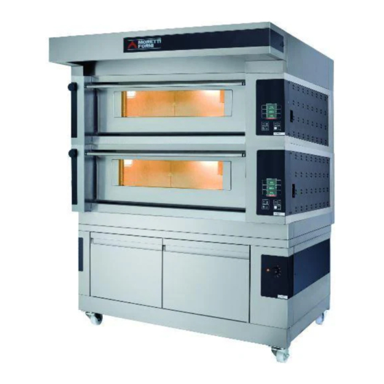
    TECHNISCHE DATEN ANMERKUNG: Nur für Backöfen, die mit Verdampfer ausgestattet sind. BESCHREIBUNG DER GERÄTE Das Gerät besteht aus mehreren übereinander liegenden Modulen: - Abzugshaube - Backofen/Backöfen - Basis - Halterung oder Gärzelle Jedes Backofenmodul ist vollkommen unabhängig und verfügt über einen elektronischen Temperaturregler, ein Sicherheitsthermostat bzw.
  • Seite 42: Anschluss Abdampfleitung

    ANMERKUNG: ANMERKUNG: Beim Zusammensetzen Diese Vorrichtung muss Abstandsrings (nur möglich mit Zelle) wie folgt vorgehen: unmittelbarer Nähe des Gerätes und an leicht zugänglichem Ort - die Räder der Zelle entfernen und unter dem Abstandsring positioniert werden. wieder in der vorbereiteten Position montieren; Die Backkammer wird mit der gewünschten Spannung geliefert (auf - bei Vorhandensein des Zubehörs Werkzeugträger die untere dem Maschinenschild ersichtlich) (Abb.1).
  • Seite 43: Elektroanschluss Von Dunstabzugshaube

    durch Symbol KLEMME FÜR - Beim Öffnen der Tür einen Sicherheitsabstand einhalten, weil ÄQUIPOTENTIONELLEN ANSCHLUSS gekennzeichnet. eventuell aus der Backkammer austretende Dämpfe Verbrühungen verursachen können. - Unbefugte Personen dürfen sich dem Gerät nicht nähern. Zur Erzielung einer größeren Gleichmäßigkeit empfehlen wir, Temperaturen zu vermeiden, die die für die Garung dieses Produkttyps vorgesehenen überschreiten.
  • Seite 44 C) Leistungsniveau des Himmels 3.2.2 INBETRIEBNAHME DER BACKKAMMER: ’ ÖKO D) effektive Temperatur /Arbeits- Set Point SMART BAKING-Modus E) Leistungsniveau des Himmels Die SMART BAKING Modus ist die Standard-Verwaltungsmodalität F) Darstellung Einschaltung/Ausschaltung Widerstände Himmel des Ofens. Ermöglicht das Einstellen von 1 Temperatur und 2 G) Darstellung Einschaltung/Ausschaltung Widerstände Boden Leistungspegeln (in Prozent) des Himmels und des Bodens (Abb.
  • Seite 45 scrollen bis zur Zeile SUCHE nach NAMEN und mittels “OK” anwählen und daraufhin “OK” drücken, um zum Untermenü. zu bestätigen. Nun zeigt das Display die alphabetische Auflistung an. Die gelangen. Auswahl bis zum Anfangsbuchstaben des gesuchten Programms Die Liste mit den Tasten AUSWAHL” durchgehen, um die folgenden scrollen.
  • Seite 46: Programme-Einstellungen

    • Zum Aktivieren/Deaktivieren der Funktion, die Taste “MENU” VOR KURZEM drücken, HALBE LADUNG mit den Tasten “AUSWAHL” auswählen Funktion, die die letzten benutzten Programme auflistet. Das und danach auf “OK” drücken. Nach der Aktivierung wird der gewünschte Programm mit den Tasten "AUSWAHL" anwählen, dann Bildschirm LILA und es erscheint eine besondere Ikone links in Bezug Ok drücken um es durchzuführen und die Heiz-/Backphase mit den auf die Backparameter.
  • Seite 47: Dampfableitung

    ausgewählten Buchstaben, zu ordnen. Das gewünschte Programm mit Steuerung Warmwasserspeichers ermöglichen, ohne den Tasten "AUSWAHL" wählen und daraufhin OK drücken, um auf entsprechende Menü gehen zu müssen. die Bildschirmseiten der Änderung zu gelangen. Die Prozedur zur einzelner Druck: Druck gelangt direkt in die Backkammer Änderung der Parameter stimmt mit der oben im Abschnitt "NEU (Abkürzung der Funktion "Dampfeinlass") EINGEBEN"...
  • Seite 48: Zündung Timer

    3.5.4 ZÜNDUNG TIMER "1" und das Display wird dafür sorgen, dass das Gerät nicht in Mit dieser Funktion ist es möglich, die Timergesteuerte Einschaltung diesem Zustand geben Ausschalten des Ofens zu programmieren und bis zu zwei Zeitpläne für die Ein- und Leistungsschalters.
  • Seite 49: Wartung

    (von weniger empfindlich empfindlicher): „Low”, INBETRIEBNAHME DES GÄRSCHRANKES „Default“(Werkseinstellung) und „High“. Auf dem rechten vorderen Ständer des Gärschrankes befindet sich ein „Slit Booster“: Funktion, die es gestattet einzustellen, in welchen Bedienfeld (siehe Abb. 24). Bereichen die Funktion Power Booster zusätzliche Leistung 1.
  • Seite 50: Längerer Nichtgebrauch

    ACHTUNG! Entfernen Sie das eventuelle beim Backen ausgetreten Fett täglich, Verbrennungen Verpuffungen führen kann. ACHTUNG! Das Gerät darf keinesfalls mit einem direkten Wasserstrahl bzw. Hochdruckreiniger abgespritzt werden. Darauf achten, dass Wasser oder eventuell verwendete Reinigungsmittel nicht mit den Elektroteilen in Berührung kommen.
  • Seite 51: Ausserordentliche Wartung

    ACHTUNG DIE FOLGENDEN ANWEISUNGEN ZUR “AUSSERORDENTLICHEN WARTUNG” RICHTEN SICH AUSSCHLIESSLICH FACHPERESONAL ORDENTGEMÄSSER LIZENZ, DAS VOM HERSTELLER ANERKANNT UND BEFUGT IST. AUSSERORDENTLICHE WARTUNG - Mit einem Schraubenzieher die Kalotte entfernen Detail 43 Tafel A (Steckverbindung ) die Glühbirne und/oder die Kalotte auswechseln; PRELIMINÄRE SICHERHEITSMASSNAHMEN - Die Kalotte wieder einsetzen.
  • Seite 52: Austausch Von Teilen Des Gärschrankes Mit Luftbefeuchter

    - Die frontseitige Tür öffnen ; - Die Steckverbindungen der Leuchte abnehmen; - Den Backboden mit Hilfe eines Schraubenziehers (Detail 4 oder 39 - Die Leuchtdiode ersetzen (Detail 1 Tafel B); Taf. A) anheben. - Bei der Remontage in umgekehrter Reihenfolge vorgehen. - Den Backboden.
  • Seite 53 DE/14...
  • Seite 54 ÍNDICE CARACTERÍSTICAS TÉCNICAS INSTALACIÓN FUNCIONAMIENTO MANTENIMIENTO ORDINARIO MANTENIMIENTO EXTRAORDINARIO CATÁLOGO DE LOS RECAMBIOS Nota: El presente manual se ha previsto para la lectura en cinco idiomas. Instrucciones originales en Italiano y traducciones de las instrucciones originales en Inglés, Francés, Alemán y Español. Para una mejor claridad y leer este manual, que podría ser proporcionada en varias partes separadas y se puede enviar por correo poniéndose en contacto con el fabricante.
  • Seite 55 CARACTERÍSTICAS TÉCNICAS aparato llegue a temperatura ambiente. Utilizar siempre adecuados dispositivos de protección individual (guantes, gafas… ). DESCRIPCIÓN DE LOS APARATOS NOTA: Sólo para cámaras de cocción provistas de vaporera. El aparato está formado por varios módulos sobrepuestos: - Campana - Cámara/s de cocción - Base - Soporte o celda de fermentación...
  • Seite 56: Conexión Eléctrica

    los pies de referencia de cada módulo en el asiento del que se encuentra NOTA: El dispositivo elegido habría de estar cerca del debajo (detalle A - fig. 5). aparato y ha de ser fácilmente accesible. NOTA: en caso de composición con anillo espaciador (es La cámara de cocción se entrega con el voltaje solicitado indicado en la posible sólo con celda), realizar las siguientes operaciones: chapa (fig.
  • Seite 57 2.5.2.3 CONEXIÓN ELÉCTRICA CAMPANA EXTRACTORA Sólo después de una secuencia de cocción obtendrá los resultados conjunto óptimo. ¡ATENCIÓN! Hace falta instalar para la campana extractora, un interruptor general bipolar con fusibles o un PUESTA EN MARCHA CÁMARA DE COCCIÓN interruptor automático adecuados a los valores que se indican en la En el lado derecho de las cámaras de cocción se encuentran los placa.
  • Seite 58: Primer Encendido

    Para ajustar los parámetros de cocción, utilizar directamente las teclas NOTA: instrumentación electrónica permite "+" y/o "-" correspondientes para aumentar y/o disminuir el parámetro. regulación más precisa y puntual del horno. Pero, por su Regular los valores de potencia del cielo y de la placa de fondo. Estos naturaleza, es una instrumentación más delicada con respecto a la valores varían de 0 (potencia desactivada) a 100% (potencia máxima).
  • Seite 59 de la que es posible introducir al menos un programa de cocción tal Desplazarse en el listado con las teclas "SELECCION" hasta la voz deseada y confirmar con la tecla "OK". Modificar el parámetro con las y como se describe en 3.3. teclas "+"...
  • Seite 60 • 3.2.3 PUESTA EN MARCHA CÁMARA DE COCCIÓN: BÚSQUEDA POR NOMBRE MODO DUAL-TEMP Es la función que proporciona el listado, en orden alfabético, de todos El modo DUAL-TEMP es el modo de gestión del horno que permite los programas presentes en la memoria a partir de la letra elegida a configurar 2 temperaturas, respectivamente de cielo y placa de fondo través de las teclas "SELECCIÓN"...
  • Seite 61: Configuración Adicional

    • crear programas que prevén en su interior vaporizaciones, tómese como IMPORTAR USB referencia el apartado 3.3. Introducir el dispositivo USB en la ranura específica presente en el De todas formas, la parada (STOP) del horno desactiva también el lateral derecho del aparato después de quitar el tapón de protección. El calentamiento de la vaporera.
  • Seite 62: Selección Del Idioma

    pantalla de las "Configuraciones" para introducir al menos un tiempo “OK” para confirmar la modificación. Apretar "RETURN" para volver de encendido/apagado. a la pantalla anterior sin confirmar las modificaciones. Colocar el cursor con las teclas "SELECCIÓN" en el campo de la hora El formato de representación de la hora es HH:MM.
  • Seite 63: Mantenimiento Ordinario

    Confirmar la voz seleccionada con la tecla "OK". Apretar "RETURN" PUESTA MARCHA CÁMARA para volver a la pantalla anterior sin confirmar las modificaciones. FERMENTACIÓN CON HUMECTADOR En el montante derecho anterior de la cámara de fermentación se 3.5.9 MULTITIMER encuentra un cuadro de mandos como el ilustrado en la figura 25. La visualización “Multitimer”...
  • Seite 64: Períodos De Inactividad

    o utensilios que puedan dañar las superficies; antes de volver a encender el aparato, prestar atención en no dejar dentro del mismo lo que ha sido utilizado para la limpieza. PERÍODOS DE INACTIVIDAD Si el aparato no se tiene que utilizar durante largos periodos: - Desenchufarlo de la alimentación eléctrica.
  • Seite 65: Limpieza General

    ATENCIÓN SIGUIENTES INSTRUCCIONES RELATIVAS “MANTENIMIENTO EXTRAORDINARIO” ESTÁN RESERVADAS PERSONAL TÉCNICO ESPECIALIZADO EN POSESIÓN DE UNA REGULAR LICENCIA, AUTORIZADO Y HABILITADO POR EL FABRICANTE. MANTENIMIENTO EXTRAORDINARIO 5.3.1 SUSTITUCIÓN DE LA LÁMPARA DE ILUMINACIÓN Tras efectuar las operaciones indicadas en el punto 5.1, la lámpara de OPERACIONES PRELIMINARES DE SEGURIDAD iluminación de la cámara de cocción se sustituye en el interior de la cámara de cocción misma.
  • Seite 66 5.3.7 SUSTITUCIÓN DE LA SUPERFICIE REFRACTARIA O - Sustituir el indicador luminoso (detalle 1 tabla B); - Para el montaje, efectuar las operaciones anteriores en orden inverso. PLANAS ALMOHADILLADAS Tras efectuar las operaciones indicadas en el punto 5.1, para sustituir la superficie hay que: 5.4.6 SUSTITUCIÓN DE LAS RESISTENCIAS...
  • Seite 67 ES/14...
  • Seite 68 S100-S120-S125 S100 S120 S125 K-KX K-KX K-KX S100 S120 S125 S100 S120 S125 S100 S120 S125...
  • Seite 69 S100L S120L S125L S100 S120 S125 S100 S120 S125 S100 S120 S125 S100 S120 S125 S100 S120 S125 S105 S105 S105 S100 S120 S125...
  • Seite 70 S100E-S120E-S125E PIZ S100E C 16 S120E C 16 S125E C 16 S100-S120-S125 S100-S120-S125 Potenza Max (kW) Puissance Max. (kW) Maximum power (kW) Höchstleistung (kW) 17,3 0,25 Potencia máx (kW) Potenza Max (kW) con FOURCE Puissance Max. (kW) avec FOURCE Maximum power (kW) with FOURCE Höchstleistung (kW) mit FOURCE 14,4 Potencia máx (kW) con FOURCE...
  • Seite 71 Fig.1 Fig.2 Fig.3...
  • Seite 72 Fig.4 Fig.5...
  • Seite 73 Fig.5.1 Fig.5.2...
  • Seite 74 Part. A Part. B Fig.5.3 Fig.6...
  • Seite 75 Fig.7 Fig.8...
  • Seite 76 Fig.9 Fig.10 Fig.11...
  • Seite 77 Fig.12 Fig.13 Fig.14...
  • Seite 78 Fig.15 Fig. 16 Fig. 17...
  • Seite 79 Fig. 18 Fig. 19...
  • Seite 80 Fig. 20...
  • Seite 81 Fig. 21 Fig 22 Fig 22A Fig.23 Fig.24 Fig.25...
  • Seite 83 Cielo post. Cielo post. Ceiling rear Cielo ant. Ceiling rear Cielo ant. Ceiling front Ceiling front Platea post. Platea post. Deck rear Deck rear Platea ant. Platea ant. Deck front Deck front 73302820 Revisione 07 S100 C/K S120 C/K S125 C/K 73302820 Revisione 06 S100 C/K S120 C/K...
  • Seite 84 Denominazione Denomination Designation Bezeichnung Denominación Assieme vetro con Logo Glass with logo Verre avec logo Glas mit Logo Vidrio con logo Interruttore Switch Interrupteur Schalter Interruptor Aspiratore Vapori Vapour Exhaust Fan Aspirateur Vapeurs Dampfabsauggebläse Aspirador De Los Vapores Piano In Lamiera Bugnata Embossed Plate Floor Plan En Tôle Gaufrée Backboden Aus Bossiertem Blech...
  • Seite 85 73302830 Revisione 02 S100 L S120 L S125 L...
  • Seite 86 Denominazione Denomination Designation Bezeichnung Denominación 1 Spia luminosa Indicator light Led lumineuse Kontrolllampe Testigo luminoso 2 Manopola Dial Poignée Drehknopf Mando 3 Termostato Thermostat Thermostat Thermostat Termostato 4 Lampadina Bulb Ampoule Lampe Lámpara 5 Portalampada Lamp holder Douille Lampensockel Portalámparas 6 Resistenza Heating element Résistance...
  • Seite 87 73302730 Revisione 00 Mod. Serie P - Serie M - Serie S Mod. S100 V - S120 V - S120W - S125 V - S125W...
  • Seite 88 Denominazione Denomination Designation Bezeichnung Denominación Vaporiera Steamer vaporisateur Dampferzeuger- equipo vapor Resistenza Heating element Résistance Widerstand Resistencia Elettrovalvola Solenoid valve Électrovanne Magnetventil Electroválvula Contattore. Contactor Contacteur Kontaktgeber Contactor Soppressore Suppressor Suppresseur Entstörer Supresor Termostato Thermostat Thermostat Thermostat Termóstato Tubo entrata acqua Water inlet tube Tuyau d'arrivée d'eau Wasser Einlauf Schlauch...
  • Seite 89 400V 230V 230V RA RB RG 12Vac S125 VAP. V (1600W) VAP. W (3200W) 230V (22) (23) (12) RA RB RG A3 BR C1 CR C2 D2 DS (26) (27) (14) 230V 74800820 Revisione 03 MOD. S100C S120C S125C V400 3N V230 3 1/1...
  • Seite 90 Rif. Denominazione Designation Denomination Bezeichnung Denominación Entrata rete elettrica Mains junction box Entrée réseau Netzeingang Borne de conexión a la red RC1-9 Resistenze cielo Ceiling heating elements Résistances ciel Widerstand oben Resistencia de la parte superior RP1-9 Resistenze platea Floor heating elements Résistances sole Widerstand unten Resistencia de la parte inferior...
  • Seite 91 400V 230V 230V RA RB RG 12Vac S125 VAP. V (1600W) I > VAP. W (3200W) 230V (23) (12) (22) A3 BR RA RB RG C1 CR C2 D2 DS (27) (14) (26) 230V 74800960 Revisione 00 MOD. S100/120/125E 'FOURCE' V400 3N V230 3...
  • Seite 92 Rif. Denominazione Designation Denomination Bezeichnung Denominación Entrata rete elettrica Mains junction box Entrée réseau Netzeingang Borne de conexión a la red RC1-9 Resistenze cielo Ceiling heating elements Résistances ciel Widerstand oben Resistencia de la parte superior RP1-9 Resistenze platea Floor heating elements Résistances sole Widerstand unten Resistencia de la parte inferior...
  • Seite 93 230V 74800840 Revisione 01 MOD. S100L/LU S120L/LU S125L/LU 230V 1N 1/1...
  • Seite 94 Rif. Denominazione Designation Denomination Bezeichnung Denominación Entrata rete elettrica Mains junction box Entrée réseau Netzeingang Borne de conexión a la red Interruttore termostato Thermostat switch Interrupteur thermostat Thermostatschalter Interruptor termostato Termostato Thermostat Thermostat Thermostat Termostato Spia termostato Thermostat light Led du thermostat Thermostatkontrolleuchte Testigo termostato Luce...
  • Seite 95 230V 50Hz 74822530 Revisione 02 MOD. P60/P80/P120/AMALFI KX - F/S KX - iD KX V2301N...
  • Seite 96 Rif. Denominazione Designation Denomination Bezeichnung Denominación Interruttore Switch Interrupteur Schalter Interruptor Motore elettrico Motor Moteur Motor Motor Condensatore Condenser Condenseur Kondensator Condensador 74822530 P60E/P80E/P120E/AMALFI KX –F/S KX – iD KX V230 1N...

Diese Anleitung auch für:

S100eS120eS125e

Inhaltsverzeichnis