Jackle JESS WELDING inoMIG 350 Betriebsanleitung
Schweißstromquelle

Verwandte Anleitungen für Jackle JESS WELDING inoMIG 350


Inhaltszusammenfassung für Jackle JESS WELDING inoMIG 350
- Seite 1 J ä c k l e & E s s S y s t e m G m b H DE Betriebsanleitung EN Operating instructions inoMIG 350/400/500 DE Schweißstromquelle EN Welding power source www.jess-welding.com...
- Seite 2 inoMIG 350/400/500 Original Betriebsanleitung Der Hersteller behält sich das Recht vor, jederzeit und ohne vorherige Mitteilung Änderungen an dieser Betriebsanleitung durchzuführen, die durch Druckfehler, eventuelle Ungenauigkeiten der enthaltenen Informationen oder Verbesserung dieses Produktes erforderlich werden. Diese Änderungen werden jedoch in neuen Ausgaben berücksichtigt. Alle in der Betriebsanleitung genannten Handelsmarken und Schutzmarken sind Eigentum der jeweiligen Besitzer/Hersteller.
-
Seite 3: Bestimmungsgemäße Verwendung
inoMIG 350/400/500 1 Identifikation 1 Identifikation Die MIG/MAG – Schweißanlagen inoMIG 350/400/500 wurden für den industriellen Einsatz entwickelt. Ihre Ausstattung und Funktionsweise wurden deshalb für die professionelle Nutzung ausgelegt. Kennzeichnung Das Produkt erfüllt die geltenden Anforderungen des jeweiligen Marktes für das Inverkehrbringen. Sofern es einer entsprechenden Kennzeichnung bedarf, ist diese am Produkt angebracht. -
Seite 4: Klassifizierung Der Warnhinweise
2 Sicherheit inoMIG 350/400/500 Klassifizierung der Warnhinweise Die in der Betriebsanleitung verwendeten Warnhinweise sind in vier verschiedene Ebenen unterteilt und werden vor potentiell gefährlichen Arbeitsschritten angegeben. Geordnet nach abnehmender Wichtigkeit bedeuten sie Folgendes: GEFAHR Bezeichnet eine unmittelbar drohende Gefahr. Wenn sie nicht gemieden wird, sind Tod oder schwerste Verletzungen die Folge. -
Seite 5: Warn- Und Hinweisschilder
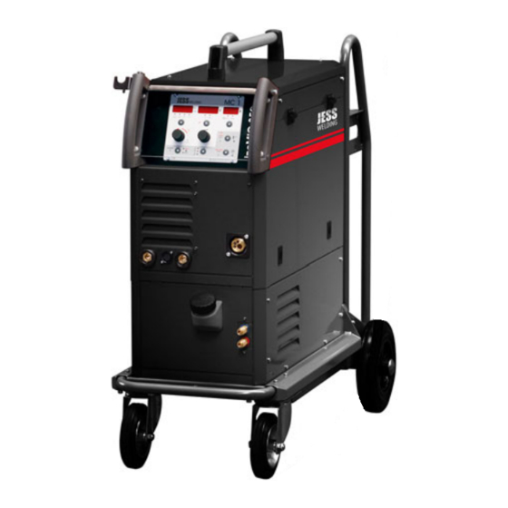
inoMIG 350/400/500 2 Sicherheit Warn- und Hinweisschilder Am Produkt befinden sich folgende Warn- und Hinweisschilder: Symbol Bedeutung Betriebsanleitung lesen und beachten! Vor dem Öffnen Netzstecker ziehen! Warnung vor heißer Oberfläche Angaben für den Notfall Unterbrechen Sie im Notfall sofort folgende Versorgungen: •... - Seite 6 3 Produktbeschreibung inoMIG 350/400/500 3 Produktbeschreibung Technische Daten Abb. 1 inoMIG 350 compact und mit DVK3 Tab. 1 Technische Daten inoMIG 300/400 Stromquelle inoMIG 350 inoMIG 400 Netzspannung, 50/60 Hz 400 V, 3 Phasen (350 V – 480 V) 400 V, 3 Phasen Stromaufnahme Imax.
- Seite 7 inoMIG 350/400/500 3 Produktbeschreibung Tab. 2 Technische Daten Drahtvorschub Drahtvorschub Kompakt/DVK3 Drahtvorschubmotor 42 V, 110 W Fördergeschwindigkeit 0,8–24 m/min Drahtdurchmesser 0,8–1,6 mm Gewicht DVK3 (solo) 20 kg Maße DVK3 L × B × H (mm) 580 × 270 × 560 Herstellung gemäß...
-
Seite 8: Umgebungsbedingungen
3 Produktbeschreibung inoMIG 350/400/500 Tab. 4 Technische Daten DVK 3 und DVK4 Drahtvorschub DVK3 DVK4 Drahtvorschubmotor 42 V, 110 W 42 V, 140 W Fördergeschwindigkeit 0,8–24 m/min 0,8–24 m/min Drahtdurchmesser 0,8–1,6 mm 0,8–1,6 mm Gewicht DVK3 (solo) 20 kg 28 kg Maße DVK3 L ×... -
Seite 9: Verwendete Zeichen Und Symbole
inoMIG 350/400/500 3 Produktbeschreibung Abb. 4 Typenschild inoMIG 400 Abb. 5 Typenschild inoMIG 500 Verwendete Zeichen und Symbole Beschreibung Symbol • Aufzählungssymbol für Handlungsanweisungen und Aufzählungen Querverweissymbol verweist auf detaillierte, ergänzende oder weiterführende Informationen Handlungsschritt/e im Text, die der Reihenfolge nach durchzuführen sind BA-0014 •... -
Seite 10: Pflege Und Sicherheitsprüfung
4 Lieferumfang inoMIG 350/400/500 4 Lieferumfang • Schweißstromquelle • Betriebsanleitung • Beipackzettel „Allgemeine Sicherheitsinformationen“ Ausrüst- und Verschleißteile separat bestellen. Bestelldaten und Identnummern der Ausrüst- und Verschleißteile entnehmen Sie den aktuellen Bestellunterlagen. Kontakt für Beratung und Bestellung finden Sie im Internet unter www.jess-welding.com. Transport Der Lieferumfang wird vor dem Versand sorgfältig geprüft und verpackt, jedoch sind Beschädigungen während des Transportes nicht auszuschließen. -
Seite 11: Funktionsbeschreibung
inoMIG 350/400/500 6 Funktionsbeschreibung 6 Funktionsbeschreibung Funktionsbeschreibung inoMIG 350 Abb. 6 Funktionsbeschreibung inoMIG 350 G Massebuchse Steuerbox MC1/MC2 Kühlgerät Buchse Elektrode Brenner Zentralanschluss Wasserrücklauf (rot), Anschluss up/down Brenner Wasservorlauf (blau) BA-0014 • 2020-10-15 DE - 11... -
Seite 12: Funktionsbeschreibung Inomig
6 Funktionsbeschreibung inoMIG 350/400/500 Funktionsbeschreibung inoMIG 400 Abb. 7 Funktionsbeschreibung inoMIG 400 G Wasserrücklauf (rot), Steuerbox MC1/MC2 Steuerbox MC1/MC2 Massebuchse Anschluss up/down Brenner Brenner Zentralanschluss Wasservorlauf (blau) Hauptschalter (Rückseite) Wasserrücklauf (rot), Kühlgerät H Buchse Elektrode Brenner Zentralanschluss Wasservorlauf (blau) Anschluss up/down Brenner DE - 12 BA-0014 •... - Seite 13 inoMIG 350/400/500 6 Funktionsbeschreibung Funktionsbeschreibung inoMIG 500 Abb. 8 Funktionsbeschreibung inoMIG 500 Vorderseite G Primärsicherung Steuerbox MC1/MC2 Buchse Elektrode Brenner Zentralanschluss Anschluss up/down Brenner Kühlgerät H Kontrollleuchte Netz Wasserrücklauf (rot), Massebuchse Hauptschalter (Rückseite) Wasservorlauf (blau) BA-0014 • 2020-10-15 DE - 13...
- Seite 14 6 Funktionsbeschreibung inoMIG 350/400/500 Abb. 9 Funktionsbeschreibung inoMIG 500 Rückseite Hauptschalter Buchse Gasausgang Netzkabel Datenleitung zum Drahtvorschubkoffer Gaseingang G Fernbedienbuchse 17-polig DE - 14 BA-0014 • 2020-10-15...
- Seite 15 inoMIG 350/400/500 7 Inbetriebnahme 7 Inbetriebnahme GEFAHR Verletzungsgefahr durch unerwarteten Anlauf Für die gesamte Dauer von Wartungs-, Instandhaltungs-, Montage- bzw. Demontage- und Reparaturarbeiten ist Folgendes zu beachten: • Schalten Sie die Stromquelle aus. • Sperren Sie die Gaszufuhr ab. • Sperren Sie die Druckluftzufuhr ab. •...
-
Seite 16: Schweißvorgang Starten
7 Inbetriebnahme inoMIG 350/400/500 MIG/MAG-Schweißen 7.1.1 Schweißbrenner-Schlauchpaket anschließen Schutzgasflasche hinten auf die Schutzgasschweißanlage setzen und mit der Kette sichern. Flaschendruckminderer anschließen und Anschlüsse auf Dichtheit prüfen. Abb. 10 Schlauchpaket anschließen Anschluss Up-/Down-Brenner Brenner Zentralanschluss Wasserrücklauf „rot-heiß“ DN 5 Massebuchse Wasservorlauf „blau-kalt“ DN 5 Schweißbrenner wie im Bild dargestellt an Zentralanschluss, Wasseranschlüssen und wenn vorhanden Up-/Down-Brenner anschließen. -
Seite 17: Hotstart Und Arcforce Einstellen
inoMIG 350/400/500 7 Inbetriebnahme 7.2.2 Schweißvorgang starten Steuerbox auf die Betriebsart Elektrode stellen, Parameter für die Schweißaufgabe einstellen und Schweißvorgang durch Aufsetzen der Elektrode auf dem Schweißstück starten. 7.2.3 Hotstart und Arcforce einstellen Um einen besseren Start des Schweißvorganges zu erhalten, kann mit dem Parameter Hotstart (Tippen auf den Fx Knopf) ein erhöhter Startstrom eingestellt werden. -
Seite 18: Parameter Downslope Und Gasnachströmen
7 Inbetriebnahme inoMIG 350/400/500 7.3.2 WIG Schweißbrenner-Schlauchpaket Schweißbrenner wie im Bild dargestellt an Massebuchse, Fernbedienungsbuchse, Wasseranschlüsse und Gasausgang anschließen. Dabei die Farben der Wasseranschlüsse beachten. Drahtvorschubkoffer mit Steuerleitung muss an der Maschine eingesteckt bleiben. 7.3.3 Potentiometer Schweißstromregelung Um die Schweißstromstärke mit einem Potentiometer im WIG Betrieb regeln zu können, muss dieses wie im Schaltplan dargestellt an der 17-poligen Fernbedienungsbuchse angeschlossen werden. -
Seite 19: Übersicht Steuerungsfunktionen
inoMIG 350/400/500 8 Übersicht Steuerungsfunktionen 8 Übersicht Steuerungsfunktionen Tab. 5 Übersicht Steuerungsfunktionen MC1 und MC2 Funktionen Inverteranlage ■ ■ Handbetrieb ■ ■ Automatikbetrieb ■ ■ Lichtbogenlängenkorrektur ■ ■ Materialauswahl ■ ■ Leistung individuell einstellbar ■ ■ MIG Modus ■ ■ WIG Modus –... -
Seite 20: Betrieb
9 Betrieb inoMIG 350/400/500 9 Betrieb HINWEIS • Jegliche Arbeiten am Gerät bzw. System sind ausschließlich befähigten Personen vorbehalten. Steuerungsfunktionen 9.1.1 Steuerung MC1 Abb. 14 Steuerbox MC1 Anzeige-Display G Auswahl Betriebsart M Bedientaste Schweißfunktionen Schweißspannung H LED-Anzeige Betriebsart N LED-Anzeige Einheiten Anzeige-Display Stromstärke LED-Anzeige Hand/Auto (% oder Sekunde) - Seite 21 inoMIG 350/400/500 9 Betrieb Pos. Beschreibung Drehknopf, um die Materialart einzustellen, die Lichtbogenlänge zu korrigieren (AUTO-(I)), die Drahtgeschwindigkeit in m/min (HAND-(I)) einzustellen bzw. um alle Werte im linken Display zu ändern Bedientaste Fx zum Einstellen der Schweißfunktionen (z.B. Drosselhärte antippen kürzer als 0,5 Sekunden) bzw.
- Seite 22 10 Bedienung / Schweißen inoMIG 350/400/500 Pos. Beschreibung Bedientaste, um die Drahteinfädelfunktion zu aktivieren bzw. um im Einstellmodus die Werte von Drossel, Einschleichgeschwindigkeit, Drahtrückbrandzeit zu, Materialdicke und Leistung zu verkleinern (LED (C) blinkt) Bedientaste Mode, um zwischen den Betriebsarten MIG, Elektrode und WIG umzuschalten LED Anzeige aktivierte Betriebsart MIG, Elektrode oder WIG LED Anzeige, Betriebsart HAND/AUTO Bedientaste für die Materialauswahl (antippen kürzer als 0,5 Sekunden) bzw.
-
Seite 23: Betriebsart Mig
inoMIG 350/400/500 10 Bedienung / Schweißen Betriebsart Beschreibung 4-Takt Der Brennertaster wird gedrückt, und der Lichtbogen wird mit dem voreingestellten Hot-Start Strom (CSC) gezündet. Der Schweißstrom bleibt auf diesem Wert. Der Brennertaster wird losgelassen und der Strom fällt auf den eingestellten Schweißstrom mit der eingestellten Absenkgeschwindigkeit (SLO) ab. -
Seite 24: Betriebsart Elektrode
10 Bedienung / Schweißen inoMIG 350/400/500 Drossel (Cho) Stufenlose Korrektur der Schweißdrossel von +15 (Weicher) bis −15 (Härter) als „0“ (Standard) Punktzeit (SPt) 0,5 bis 10 Sekunden Code (CODE) Zum Sperren der Steuerung (siehe 10.15 auf Seite DE-25) HINWEIS *MC1 nur bei Kraterfüllen (LED S) aktiv 10.8 Betriebsart Elektrode Hotstart (HSt) 0 bis 150 % des Schweißstromes... -
Seite 25: Bedienung / Schweißen
inoMIG 350/400/500 10 Bedienung / Schweißen ► (D) wird immer zuerst der zuletzt geänderte Parameter Bei erneutem Drücken der Bedientaste angezeigt. Durch erneutes Tippen auf die Taste wird zum nächsten Parameter gewechselt. 10.15 Steuerung sperren – CODE (MC1) Die Steuerung für die Schweißaufgabe optimal einstellen. Um nun ein Verändern der Einstellungen durch Dritte zu verhindern, kann die Steuerung gesperrt werden. -
Seite 26: Kühlmittel - Durchflussanzeige (Mc1)
10 Bedienung / Schweißen inoMIG 350/400/500 10.18 Kühlmittel – Durchflussanzeige (MC1) Um den aktuellen Durchfluss des Kühlmittels im Kühlkreislaufsystem anzuzeigen, muss die Bedientaste l/min lang gedrückt werden. Die LED l/min leuchtet auf, und im rechten Display wird der aktuelle Wert dargestellt (z.B. -
Seite 27: Drahtvorschub Dvk3 / Dvk4
inoMIG 350/400/500 11 Drahtvorschub DVK3 / DVK4 HINWEIS Es muss bei diesem Maschinentyp die Anzeige „CAn“ im rechten Display verwendet werden. Die Werte mit der Anzeige „int“ funktionieren bei diesem Maschinentyp nicht! z.B. EC1 - Choc - CAn Nun kann mit dem Poti 1 die Drossel verändert werden. 11 Drahtvorschub DVK3 / DVK4 11.1 DVK3 –... -
Seite 28: Drahtförderung Im Brennerschlauchpaket
11 Drahtvorschub DVK3 / DVK4 inoMIG 350/400/500 11.2 DVK4 – 140 W Motor Abb. 18 Drahtvorschubmotor 140 W Drehgriff Drahtführungsrohr Drahtvorschubrolle oben Drahtvorschubrolle unten Inbusschraube Vierrollenantrieb Vier untereinander verzahnte Drahtvorschubrollen sorgen für einen sicheren Transport des Schweißdrahts. Für den verwendeten Draht muss jeweils die Drahtvorschubrolle mit der entsprechenden Nut eingesetzt werden. -
Seite 29: Fernbedienungsdose
inoMIG 350/400/500 12 Fernbedienungsdose 12 Fernbedienungsdose Tab. 6 Belegung Fernbedienungsdose Bezeichnung Beschreibung U-Ist Ausgangssignal zwischen 0 V und +10 V. Hier wird im Verhältnis 10:1 die aktuelle Schweißspannung für Steuerungszwecke ausgegeben. Beispiel: 40 V Schweißspannung = 4,0 V Signalspannung Eingangsimpedanz muss ≥10k Ω. Das Bezugspotential ist Pin 3. I-Ist Ausgangssignal zwischen 0 V und +10 V. -
Seite 30: Schweißbrenner Mit Display
13 Schweißbrenner mit Display inoMIG 350/400/500 13 Schweißbrenner mit Display HINWEIS Brenner nur bei ausgeschalteter Maschine wechseln. 13.1 Funktionen (nach Steuerbox sortiert) Tab. 7 Funktionen nach Steuerbox ■ ■ ■* ■ ■ ■ ■ ■ ■ ■ ■ ■ ■ ■... -
Seite 31: Mode Automatik Oder Hand Schweißen
inoMIG 350/400/500 14 Funktionen mit erweiterter Auswahl 14 Funktionen mit erweiterter Auswahl 14.1 Funktion MODE (Mod) Mode 2-Takt / 4-Takt / Punkten - Krater: Mit der − Taste wird zwischen 2-Takt (2) und 4-Takt (4) gewechselt. (Anzeige linkes Display 2 oder 4) Mit der + Taste wird zwischen Normalbetrieb (−), Punkten (S) oder Krater (C) gewechselt. -
Seite 32: Funktionsweise
15 Schweißbrennerkühlung / Kühlmittel inoMIG 350/400/500 15 Schweißbrennerkühlung / Kühlmittel HINWEIS Maximaler Betriebsdruck: 3,2bar Funktionsweise Die Schweißbrennerkühlung basiert auf der Funktion einer Rückkühlanlage, d.h. die Kühlflüssigkeit wird durch einen Wärmetauscher auf annähernd Raumtemperatur zurückgekühlt, mit Hilfe der vom Ventilator umgewälzten Raumluft. Wassergekühlter Brenner Ein eingebautes Wasserkühlsystem mit leise laufender Pumpe kühlt den Brenner. -
Seite 33: Störungen Und Deren Beseitigung
inoMIG 350/400/500 17 Störungen und deren Beseitigung 17 Störungen und deren Beseitigung GEFAHR Verletzungsgefahr und Geräteschäden durch unautorisierte Personen Unsachgemäße Reparaturen und Änderungen am Produkt können zu erheblichen Verletzungen und Geräteschäden führen. Die Produktgarantie erlischt bei Eingriff durch unautorisierte Personen. •Jegliche Arbeiten am Gerät bzw. - Seite 34 18 Fehlertabelle ERROR CODES inoMIG 350/400/500 Tab. 9 Störungen und deren Behebung Störung Ursache Behebung Poröse Schweißnaht Unsaubere Werkstückoberfläche (Farbe, Oberfläche reinigen Rost, Öl, Fett) Kein Schutzgas (Magnetventil öffnet nicht) Magnetventil prüfen / wechseln, Gasflasche prüfen Zu wenig Schutzgas Schutzgasmenge am Druckminderer prüfen Gasführung auf Gasverlust prüfen mit Gasmessrohr Draht brennt bei Schweißbeginn in die...
- Seite 35 inoMIG 350/400/500 19 Materialtabelle 19 Materialtabelle Folgende Materialien sind standardmäßig in der Steuerung programmiert: Tab. 12 Materialtabelle Material Display MC Display MC Durchmesser mm Stahl* Argon 82 %, CO 18 % – MIX 18 Ar82 0,8–1,0–1,2–1,6 Stahl* Argon 90 %, CO 5 %, O Ar90 0,8–1,0–1,2–1,6...
- Seite 36 20 Ersatzteilliste inoMIG 350/400/500 20 Ersatzteilliste 20.1 Ersatzteilliste inoMIG 300/400 Abb. 19 inoMIG 300/400 Frontansicht DE - 36 BA-0014 • 2020-10-15...
- Seite 37 inoMIG 350/400/500 20 Ersatzteilliste Tab. 13 Ersatzteilliste inoMIG 300/400 außen Bezeichnung Art.-Nr. Handgriff komplett 715.032.059 Haube 715.032.071 Scharnierblech 715.032073 Scharnier 303.032.005 Steuerbox MC1 851.044.001 Steuerbox MC2 851.044.002 Feinsicherung T 6,3 A Steuerplatine 464.036.010 Drehknopf 28 mm 305.042.010 Deckel für Knopf 305.042.010 Klappe rechts 715.032.072...
- Seite 38 20 Ersatzteilliste inoMIG 350/400/500 Abb. 20 inoMIG 300/400 Seitenansicht DE - 38 BA-0014 • 2020-10-15...
- Seite 39 inoMIG 350/400/500 20 Ersatzteilliste Tab. 14 Ersatzteilliste inoMIG 300/400 innen Pos. Bezeichnung Art.-Nr. Magnetventil NW 2,5 / 42 V G 1/8 465.018.009 Gasschlauch 709.150.001 Kette 20 Glieder 101.040.020 Flaschenhaltebügel rts FG10 715.032.642 Pumpe mit Lüfterrad 400 V/50–60 Hz 456.220.300 Lagerpuffer Typ A20×15-M6 310.215.030 Kondensator 6,0 µF 453.230.002...
-
Seite 40: Ersatzteilliste Dvk3
20 Ersatzteilliste inoMIG 350/400/500 20.2 Ersatzteilliste DVK3 Abb. 21 Ersatzteilliste DVK3 DE - 40 BA-0014 • 2020-10-15... - Seite 41 inoMIG 350/400/500 20 Ersatzteilliste Tab. 15 Ersatzteilliste DVK3 Pos. Bezeichnung Art.-Nr. Haube DVK3 – 2010 715.042.206 Seitenblech rechts DVK3 – 2010 715.042.207 Kunststoffgriff klein 305.044.002 Steuerbox MC1 851.044.001 Feinsicherung T 6,3 A Steuerplatine 464.036.010 Drehknopf 28 mm 305.042.010 Deckel für Knopf 305.042.011 Tucheldose 7-polig 410.007.111...
-
Seite 42: Ersatzteilliste Inomig
20 Ersatzteilliste inoMIG 350/400/500 20.3 Ersatzteilliste inoMIG 500 Abb. 22 inoMIG 500 Frontansicht DE - 42 BA-0014 • 2020-10-15... - Seite 43 inoMIG 350/400/500 20 Ersatzteilliste Tab. 16 Ersatzteilliste inoMIG 500 außen Pos. Bezeichnung Art.-Nr. Drehdorn DVK3 715.032.163 Drehdorn DVK4 715.044.342 Haube 715.032.160 Seitenblech rechts 715.032.166 Frontfolie inoMIG 500 304.032.305 Frontteil inoMIG 500 715.032.152 Seitenblech rechts KG10 715.032.555 Blindplatte KG10 715.032.510 Schutzbügel vorne FG10 715.032.650 Hauptschalter 440.233.010...
- Seite 44 20 Ersatzteilliste inoMIG 350/400/500 Abb. 23 Seitenansicht inoMIG 500 DE - 44 BA-0014 • 2020-10-15...
- Seite 45 inoMIG 350/400/500 20 Ersatzteilliste Tab. 17 Ersatzteilliste inoMIG 500 innen Pos. Bezeichnung Art.-Nr. Flaschenhaltebügel rts FG10 715.032.642 Einbaubuchse Fernbedienung 17-polig 410.017.099 Kabelstecker 17-polig 410.017.100 Schutzkappe 310.350.051 Gasschlauch 709.150.001 Axialventilator 130 mm; H = 38 mm 450.130.002 Rückenteil inoMIG 500 715.032.360 Pumpe mit Lüfterrad 400 V/50–60 Hz 456.220.400 Lagerpuffer Typ A20 ×...
-
Seite 46: Ersatzteilliste Dvk4
20 Ersatzteilliste inoMIG 350/400/500 20.4 Ersatzteilliste DVK4 Abb. 24 Ersatzteilliste DVK4 DE - 46 BA-0014 • 2020-10-15... - Seite 47 inoMIG 350/400/500 20 Ersatzteilliste Tab. 18 Ersatzteilliste DVK4 Pos. Bezeichnung Art.-Nr. Scharnier 40 × 40 mm 303.056.003 Scharnierblech DVK4 – 2010 715.013.211 Kunststoffgriff klein 305.044.002 Schraube Torx PT60 271.060.001 Steuerbox MC1 851.044.001 Feinsicherung T 6,3 A Steuerplatine 464.036.010 Drehknopf 28 mm 305.042.010 Deckel für Knopf 305.042.011...
-
Seite 48: Ersatzteile Dvk3-Mc-R
20 Ersatzteilliste inoMIG 350/400/500 20.5 Ersatzteile DVK3-MC-R Abb. 25 Ersatzteilliste DVK3-MC-R DE - 48 BA-0014 • 2020-10-15... - Seite 49 inoMIG 350/400/500 20 Ersatzteilliste Tab. 19 Ersatzteilliste DVK3-MC-R Pos. Bezeichnung Art.-Nr. Haube DVK3 – 2010 715.042.206 Seitenblech rechts DVK3 – 2010 715.042.207 Drehknopf 21 mm (Option) 305.020.050 Deckel für Knopf (Option) 305.020.051 Frontplatte MC-R 715.011.061 Drehknopf 28 mm (Option) 305.042.010 Deckel für Knopf (Option) 305.042.011 Tucheldose 7-polig...
- Seite 50 21 Schaltpläne inoMIG 350/400/500 21 Schaltpläne 21.1 inoMIG 350/400 Abb. 26 Kompakt-Maschine DE - 50 BA-0014 • 2020-10-15...
- Seite 51 inoMIG 350/400/500 21 Schaltpläne Abb. 27 Maschine mit Koffer BA-0014 • 2020-10-15 DE - 51...
- Seite 52 21 Schaltpläne inoMIG 350/400/500 Abb. 28 Kompakt-Maschine mit Koffer DE - 52 BA-0014 • 2020-10-15...
- Seite 53 inoMIG 350/400/500 21 Schaltpläne 21.2 inoMIG 500 Abb. 29 inoMIG 500 Standard BA-0014 • 2020-10-15 DE - 53...
- Seite 54 21 Schaltpläne inoMIG 350/400/500 Abb. 30 inoMIG 500 mit MC-R – Platine im Koffer DE - 54 BA-0014 • 2020-10-15...
- Seite 55 inoMIG 350/400/500 Notizen Notizen BA-0014 • 2020-10-15 DE - 55...
- Seite 109 inoMIG 350/400/500 Notes Notes BA-0014 • 2020-06-05 EN - 55...
- Seite 110 Notes inoMIG 350/400/500 Notes EN - 56 BA-0014 • 2020-06-05...
- Seite 111 inoMIG 350/400/500 Notes Notes BA-0014 • 2020-06-05 EN - 57...