Inhaltsverzeichnis
Werbung
Verfügbare Sprachen
Verfügbare Sprachen
Quicklinks
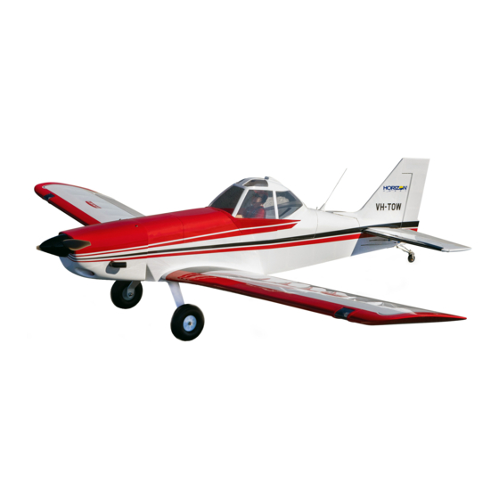
Pawnee Brave 20cc
Scan the QR code and select the Manuals and Support quick links from the product
page for the most up-to-date manual information.
Scannen Sie den QR-Code und wählen Sie auf der Produktseite die Quicklinks
Handbücher und Unterstützung, um die aktuellsten Informationen zu Handbücher.
Scannez le code QR et sélectionnez les liens rapides Manuals and Support sur la
page du produit pour obtenir les informations les plus récentes sur le manuel.
Scannerizzare il codice QR e selezionare i Link veloci Manuali e Supporto dalla
pagina del prodotto per le informazioni manuali più aggiornate.
HAN7035
Created 06/2022
Instruction Manual
Bedienungsanleitung
Manuel d'utilisation
Manuale di Istruzioni
Werbung
Inhaltsverzeichnis

Verwandte Anleitungen für Horizon Hobby HANGAR 9 Pawnee Brave 20cc


Inhaltszusammenfassung für Horizon Hobby HANGAR 9 Pawnee Brave 20cc
- Seite 1 Pawnee Brave 20cc Instruction Manual Bedienungsanleitung Manuel d’utilisation Manuale di Istruzioni Scan the QR code and select the Manuals and Support quick links from the product page for the most up-to-date manual information. Scannen Sie den QR-Code und wählen Sie auf der Produktseite die Quicklinks Handbücher und Unterstützung, um die aktuellsten Informationen zu Handbücher.
-
Seite 2: Notice
Horizon Hobby, LLC. This manual contains instructions for safety, operation and maintenance. It is essential to read and follow all the instructions and warnings in the manual, prior to assembly, setup or use, in order to operate IMPORTANT FEDERAL AVIATION ADMINISTRATION (FAA) INFORMATION correctly and avoid damage or serious injury. -
Seite 3: Inhaltsverzeichnis
TABLE OF CONTENTS REPLACEMENT PARTS Notice ..................................2 Item # Description Meaning of Special Language ..........................2 HAN703501 Fuselage Safety Warnings and Precautions ..........................2 HAN703502 Wing; Left-Hand Safe Operating Recommendations ...........................2 HAN703503 Wing; Right-Hand Before Starting Assembly ............................2 Important Federal Aviation Administration (FAA) Information ..................2 HAN703504 Stabilizer and Elevator Replacement Parts ..............................3 HAN703505 Fin and Rudder... -
Seite 4: Required For Completion, All Power Options
REQUIRED FOR COMPLETION, ALL POWER OPTIONS TOOLS REQUIRED # Required Item # Description Description SPMA3004 Heavy-Duty Servo Extension 18-inch Box or open end wrench: 10mm, 7/16-inch, 1/2-inch SPMAR8360T AR8360T 8CH SAFE Telemetry RX Clamps SPMA3000 Heavy-Duty Servo Extension 3-inch Covering iron SPMA3001 Heavy-Duty Servo Extension 6-inch Cutoff wheel for rotary tool... -
Seite 5: Removing Wrinkles
REMOVING WRINKLES AILERON CONTROL HORN INSTALLATION The covering of your model may develop wrinkles during shipping. Use a covering iron with a sealing iron sock Use a felt-tipped pen to mark the center of the slot in the (HAN141) to remove them. Start with a lower heat setting and use caution while working around areas where the hinges on both the wing and control surfaces. -
Seite 6: Aileron And Flap Hinging
Use low-tack tape around the control horns to prevent epoxy 11. Before the epoxy fully cures, remove the tape from around from getting on the control surface. the control horn. This will allow the epoxy to fl ow around the control horn, creating a small fi... -
Seite 7: Aileron Servo Installation
16. Remove the T-pins from the hinges. 21. Once the CA has fully cured, gently pull on the wing and aileron to make sure the hinges are secure. 17. Check the gap between the aileron at the wing tip. 22. Break in the hinges by fl exing the control surface through its range of motion in both directions. - Seite 8 25. Use a #1 Phillips screwdriver to thread an M2.5 x 10 self- 30. Center the servo using the radio system. Place the control tapping screw into each of the holes. Remove the screws horn on the servo so it is perpendicular to the servo. Remove before proceeding.
-
Seite 9: Flap Servo Installation
35. Locate the linkage for the ailerons. With the clevis removed, 39. Once aligned, slide the silicone retainer over the forks of the the linkage will measure 3 inches (80mm). clevis. Thread the nut away from the clevis. Apply a small drop of threadlock on the threads near the clevis. -
Seite 10: Landing Light Installation
44. With the fl ap servo centered using the radio system, adjust 49. The landing light cover for the landing light is not symmetrical the linkage to achieve the 1 inch (25mm) mid-fl ap throw. and will conform to the airfoil of the wing. Make sure it is oriented the correct direction when gluing it in place. -
Seite 11: Stabilizer Installation
STABILIZER INSTALLATION Repeat the steps to secure the remaining wing panel on the fuselage. 54. Remove the canopy hatch from the fuselage by sliding the latch located behind the hatch rearward. Lift the hatch at the rear and remove it from the fuselage. Set it aside in a safe location. -
Seite 12: Vertical Stabilizer Installation
64. Use a hobby knife with a #11 blade to carefully cut the VERTICAL STABILIZER INSTALLATION covering 1/8 inch (3 mm) inside the line drawn on the bottom of the stabilizer to remove the covering from the center of 69. Remove the rudder and hinges from the fi n. Place the fi n on the stabilizer. -
Seite 13: Rudder Installation
74. Position the fi n back on the fuselage. Use a paper towel and 79. Use a drill and 1.5mm drill bit to drill the two holes for the a small amount of isopropyl alcohol to remove any excess tailwheel arm mounting screws. epoxy from the fuselage and stabilizer before the epoxy fully cures. -
Seite 14: Elevator Servo Installation
84. Attach the tail wheel bracket to the bottom of the fuselage 89. When attaching the linkage to the servo arm, use the hole using the two M3 x 12 socket head screws. Use a 2.5mm hex that is 13/16 in (21mm) from the center of the servo horn. wrench to tighten the screws. -
Seite 15: Rudder Servo Installation
94. Slice the connector toward the servo. The two elevator 99. Center the rudder servo using the radio system. Remove the pushrods can then be inserted into the outer holes of the clevis and nut from the rudder pushrod and slide it into the connector. -
Seite 16: Landing Gear Installation
The receiver batteries can also be mounted on the bottom 107. Fit the wheel to the axle, then install the remaining wheel of the fuselage to provide more room on the servo tray. collar on the axle. Make sure the setscrew is tightened on the fl... - Seite 17 112. Use a #2 Phillips screwdriver to attach the X-mount to the 117. Slide the plate back and apply a thin coat of 30-minute epoxy rear of the motor. Use a 2.5mm hex wrench to attach the to the motor box where the plate comes in contact with the propeller adapter to the front of the motor.
-
Seite 18: Gas Engine Installation
122. Remove the plate from the fuselage to allow cooling air to 127. Apply hook and loop tape to the battery tray. enter the fuselage. 123. Thread the 1/4-20 nylon bolt into the threaded insert from the 128. Use the hook and loop straps and tape to secure the batteries bottom of the battery tray. - Seite 19 131. Fit the engine between the engine mounts. Adjust the engine 136. Slide the throttle pushrod tube into the hole in the fi rewall. so the face of the drive washer is 5 -inches (141mm) Once installed, the tube will protrude 1/16 inch (1.5mm) from forward of the fi...
- Seite 20 142. Center the servo using the radio system and install the servo arm on the servo, perpendicular to the servo center line 140. Install the throttle servo in the fuselage using the hardware 143. Move the carburetor and servo to the low-throttle position included with the servo.
-
Seite 21: Fuel Tank Installation
147. Remove the covering from the side of the fuselage using a 151. Insert the clunks into the tank. Install the larger clunk, then hobby knife and #11 blade. Mount the ignition switch and the small clunk. Mark the lines from the tank so the fuel lines connect the appropriate lead to the ignition module and can be identifi... -
Seite 22: Cowling Installation
156. Use a sanding block and medium grit sandpaper to sand the 161. The vent line fi tting is mounted on the underside of the bolt fl ush with the top of the tray so it doesn’t damage the fuselage. Attach the vent line to the fi tting. fuel tank when it is mounted to the tray. -
Seite 23: Canopy Hatch Assembly
When flying in higher temperatures, the cowling can 166. Once aligned, mark the locations for the cowl mounting screws on the cowl using a felt-tipped pen. be modified to force more air over the engine. Trim the cowling to provide an additional air inlet to the engine. ... -
Seite 24: Center Of Gravity
173. Use canopy glue to attach the viewing window to the cockpit. CENTER OF GRAVITY Use low-tack tape to hold the viewing window in position until the adhesive fully cures. CAUTION: You must adjust your aircraft’s center of gravity and balance your model properly before attempting fl ights. An important part of preparing the aircraft for fl... -
Seite 25: Control Throws
(iii) Right inches (50mm) modifi cation of or to any part of the Product, (iv) attempted service by anyone other than a Horizon Hobby authorized Rudder Left... -
Seite 26: Warranty And Service Contact Information
Union D 22885 Barsbüttel, Germany Sales: Horizon Hobby GmbH +49 (0) 4121 2655 100 calling Horizon, you will be asked to provide your complete name, street address, email address and phone number where you can be reached during business hours. When sending product into Horizon, please include your RMA number, a list of the included items, and a brief summary of the problem. -
Seite 27: Academy Of Model Aeronautics National Model Aircraft Safety Code
ACADEMY OF MODEL AERONAUTICS NATIONAL MODEL AIRCRAFT SAFETY CODE BUILDING NOTES Effective January 1, 2018 A model aircraft is a non-human-carrying device capable of sustained fl ight within visual line of sight of the pilot or spotter(s). It may not exceed limitations of this code and is intended exclusively for sport, recreation, education and/or competition. -
Seite 28: Hinweis
HINWEIS Befolgen Sie alle im Handbuch für Ihre spezielle Turbine beschriebenen Sicherheitsvorkehrungen für Turbinen. Weitere Alle Anweisungen, Garantien und andere Begleitdokumente können von Horizon Hobby, LLC nach eigenem Ermessen Einzelheiten fi nden Sie auf der Website von AMA. (https://www.modelaircraft.org/system/fi les/documents/510-A.pdf) geändert werden. -
Seite 29: Ersatzteile
INHALTSVERZEICHNIS ERSATZTEILE Hinweis .................................28 Artikel Nr. Beschreibung Spezielle Bedeutungen ............................28 HAN703501 Rumpf Warnungen und Sicherheits-vorkehrungen ......................28 HAN703502 Tragfl äche, linke Seite Empfehlungen zum sicheren Betrieb ........................28 HAN703503 Tragfl äche, rechte Seite Vor dem Zusammenbau ............................28 Ersatzteile ................................29 HAN703504 Höhenruderset Sonderzubehör ..............................29 HAN703505 Finne u. -
Seite 30: Zur Fertigstellung Erforderlich, Alle Antriebsoptionen
ZUR FERTIGSTELLUNG ERFORDERLICH, ALLE ANTRIEBSOPTIONEN WERKZEUGE ERFORDERLICH Erforderliche Artikel Nr. Beschreibung Description Anz. Ring- oder Maulschlüssel: 10 mm, 11 mm (7/16 Zoll), 13 mm (1/2 Zoll) SPMA3004 Servokabelverlängerung 450 mm (18 inch) Schraubzwinge SPMAR8360T AR8360T SAFE-Telemetrieempfänger mit 8 Kanälen Folienbügeleisen SPMA3000 Servokabelverlängerung 75 mm (3 inch) Trennscheibe für Rotationswerkzeug SPMA3001 Servokabelverlängerung 150 mm (6 inch) -
Seite 31: Falten Entfernen
FALTEN ENTFERNEN MONTAGE DES QUERRUDER-STEUERHORNS Durch den Versand können an der Abdeckung Ihres Modells Falten entstehen. Mithilfe eines Heißsiegelgeräts Mit einem Filzstift die Mitte des Schlitzes in den und Folienbügeleisen-Schutzbezug (HAN141) können diese entfernt werden. Fangen Sie mit einer niedrigen Aufhängungen auf der Tragfl... -
Seite 32: Querruder- Und Klappenaufhängung
Verwenden Sie Klebeband mit geringer Klebkraft um die 11. Ehe das Epoxid vollständig ausgehärtet ist, das Klebeband Steuerhörner, um zu verhindern, dass Epoxidharz auf die um das Steuerhorn entfernen. Dadurch kann das Epoxid um Steuerfl äche gelangt. das Steuerhorn fl ießen und für eine kleine Leiste zwischen Steuerhorn und Oberfl... -
Seite 33: Montage Des Querruder-Servos
16. Die T-Stifte von den Aufhängungen entfernen. 21. Nachdem das CA vollständig gehärtet ist, vorsichtig an Tragfl äche und Querruder ziehen, um sicherzustellen, dass die Aufhängungen sicher verklebt sind. 17. Den Spalt zwischen dem Querruder an der Tragfl ächenspitze 22. Um die Aufhängungen einzuarbeiten die Steuerfl äche über prüfen. - Seite 34 25. Mit einem Nr. 1 Kreuzschlitzschraubendreher eine M2,5 x 10 30. Den Servo mit dem Funksystem zentrieren. Das Steuerhorn Blechschraube in jedes Loch schrauben. Die Schrauben vor auf den Servo platzieren, sodass es senkrecht zum Servo dem Fortfahren entfernen. steht. Alle Arme, die den Betrieb des Servos beeinträchtigen werden, vom Servohorn entfernen.
-
Seite 35: Montage Des Klappen-Servos
35. Das Gestänge für die Querruder lokalisieren. Wenn der 39. Nach dem Justieren den Silikonhalter über die Zinken des Gabelkopf entfernt ist, misst das Gestänge 80 mm (3 Zoll). Gabelkopfs schieben. Die Mutter vom Gabelkopf abschrauben. Einen kleinen Tropfen Gewindesicherung auf die Gewinde ... -
Seite 36: Montage Der Landescheinwerfer
44. Bei mithilfe des Funksystems mittig ausgerichtetem 49. Die Landelichtabdeckung für das Landelicht ist nicht Klappenservo das Gestänge so ausrichten, dass der mittlere symmetrisch und passt sich dem Profi l des Flügels an. Beim Klappenausschlag von 25 mm (1 Zoll) erreicht wird. Ankleben darauf achten, dass es in die richtige Richtung zeigt. -
Seite 37: Montage Des Stabilisators
MONTAGE DES STABILISATORS Die Schritte zum Sichern der verbleibenden Tragfläche am Rumpf wiederholen. 54. Durch Nachhintenschieben des Riegels hinter der Klappe die Kanzelabdeckung vom Rumpf entfernen. Die Kanzelabdeckung hinten anheben und vom Rumpf entfernen. An einem sicheren Ort ablegen. 55. Die Steckungsrohre in die Steckungsrohrbuchsen schieben. 60. -
Seite 38: Montage Des Seitenleitwerks
64. Mit einem Hobbymesser und einer Klinge Nr. 11 die MONTAGE DES SEITENLEITWERKS Abdeckung 3 mm (1/8 Zoll) innerhalb der gezogenen Linie auf der Unterseite des Stabilisators schneiden, um die Abdeckung 69. Seitenruder und Aufhängungen vom Seitenleitwerk entfernen. in der Mitte des Stabilisators zu entfernen. Vorsicht walten Das Seitenleitwerk auf den Stabilisator legen und den Umriss mit einem Filzstift auf der Oberseite des Stabilisators lassen, um nicht in das darunterliegende Holz zu schneiden,... -
Seite 39: Montage Des Seitenruders
74. Das Seitenleitwerk wieder auf dem Rumpf befestigen. Mit 79. Mit einem 1,5 mm Bohreinsatz die zwei Löcher für die einem Papiertuch und etwas Isopropylalkohol überschüssiges Befestigungsschrauben des Spornradarms bohren. Epoxid von Rumpf und Stabilisator entfernen, bevor das Epoxid vollständig aushärtet. Mit einem Klebeband mit geringer Klebekraft das Seitenleitwerk in Position halten, bis der Kleber vollständig ausgehärtet ist. -
Seite 40: Montage Des Servos Des Höhenruders
84. Die Spornradhalterung mit zwei M3 x 12 89. Beim Anbringen des Gabelkopfes am Servoarm das Loch Zylinderkopfschrauben an der Unterseite des Rumpfs im Arm verwenden, das 21 mm (13/16 Zoll) von der Mitte befestigen. Die Schrauben mit einem 2,5mm Sechskant des Servohorns entfernt liegt. Dieses Loch muss mit einem festziehen. -
Seite 41: Montage Des Servos Des Seitenruders
94. Den Verbinder in Richtung Servo schieben. Die beiden 99. Den Seitenruder-Servo mit dem Funksystem zentrieren. Gestänge des Höhenruders können dann in die äußeren Gabelkopf und Mutter vom Seitenrudergestänge entfernen Löcher des Verbinders gesteckt werden. und in das Rohr des Seitenrudergestänges im Rumpf schieben. -
Seite 42: Montage Des Fahrwerks
Die Empfängerakkus können auch auf der 107. Rad in die Achse einsetzen und die verbleibende Unterseite des Rumpfes montiert werden, um mehr Anschlaghülse auf die Achse aufsetzen. Darauf achten, Platz auf der Servohalterung zu schaffen. die Einstellschrauben am fl achen Bereich an der Achse anzuziehen. - Seite 43 112. Mit einem Nr. 2 Kreuzschlitzschraubendreher die X-Halterung 117. Die Platte zurückschieben und eine dünne Schicht auf der Rückseite des Motors anbringen. Mit einem 2,5 mm 30-Minuten-Epoxid auf den Motorkasten auftragen, wo die Nr. 2 Sechskant den Propelleradapter auf der Vorderseite Platte mit dem Kasten in Kontakt kommt. des Motors anbringen.
-
Seite 44: Montage Des Benzinmotors
122. Die Platte vom Rumpf entfernen, damit Kühlluft in den Rumpf 127. Klettband an der Akkuhalterung befestigen. eindringen kann. 123. Die 1/4-20 Nylonschraube in den Gewindeeinsatz an der 128. Den Akku mit den mitgelieferten Klettbändern an der Unterseite des Akkufachs einschrauben. Akkuhalterung sichern. - Seite 45 131. Den Motor zwischen die Motorhalterungen einpassen. 136. Das Rohr des Gasgestänges durch die Öffnung im Den Motor so positionieren, dass sich die Vorderseite der Brandschott schieben. Nach der Installation ragt das Rohr 1,5 Unterlegscheibe des Motors 141 mm (5 Zoll) vor dem mm (1/16 Zoll) aus dem Brandschott heraus.
- Seite 46 142. Das Servo mit dem Funksystem zentrieren und den Servoarm auf dem Servo senkrecht zur Mittellinie des Servos montieren. 140. Das Gas-Servo im Rumpf mithilfe der mit dem Servo 143. Vergaser und Servo auf niedrigere Gaszufuhr stellen und mitgelieferten Hardware montieren. Der Ausgang des Servos die Feststellschraube festziehen, die das Gestänge am zeigt zur Rückseite des Rumpfes.
-
Seite 47: Montage Des Kraftstofftanks
147. Die Abdeckung von der Seite des Rumpfes mit einem 151. Die Pendel in den Kraftstofftank einführen. Erst das Hobbymesser und einer Nr. 11 Klinge entfernen. Den große Pendel und dann das kleinere Pendel montieren. Zündschalter montieren und das entsprechende Kabel mit Markieren Sie die Leitungen vom Tank aus, sodass die dem Zündmodul und dem Zündakku verbinden. -
Seite 48: Montage Der Motorhaube
155. Die Halterung aus dem Rumpf nehmen und mit einem 160. Einen Kraftstoffeinfüllstutzen an der Seite des Rumpfes Seitenschneider die überstehende Schraube von der einbauen und die Kraftstoffeinfüllleitung verlegen. Oberseite der Halterung entfernen. 156. Mit Schleifklotz und Schleifpapier mittlerer Körnung den 161. -
Seite 49: Montage Der Kanzelabdeckung
165. Den Spinnerkegel an der Spinner-Rückplatte anbringen, um 170. Den Propeller und die Spinner-Rückplatte an der Motorwelle die Ausrichtung der Motorhaube weiter zu überprüfen. Die sichern. Den Spinnerkegel mit den mit dem Spinner Motorhaube sitzt etwas höher als der Spinner, was für dieses mitgelieferten Schrauben anbringen. -
Seite 50: Schwerpunkt
172. Das Sichtfenster mit einer Hobbyschere und einem SCHWERPUNKT Hobbymesser mit einer 11er-Klinge zuschneiden. ACHTUNG: Vor einem Flug muss der Schwerpunkt des Flugzeugs ausgerichtet und das Flugzeug ordnungsgemäß ausbalanciert sein. Ein wichtiger Teil bei der Vorbereitung des Flugzeugs für den Flug ist das ordnungsgemäße Ausbalancieren des Modells. -
Seite 51: Ruderausschlag
RUDERAUSSCHLAG VORFLUGKONTROLLE • Akkus für Sender, Empfänger und Motor aufl aden. Die dem Ladegerät beigelegten Anweisungen befolgen. Die Den Sender und Empfänger des Modells einschalten. Die Bewegung des Seitenruders mit dem Empfänger prüfen. Anweisungen des Herstellers der elektrischen Bauteile befolgen. Wird der Hebel nach rechts bewegt, sollte sich auch das Seitenruder nach rechts bewegen. -
Seite 52: Ntie Und Service Informationen
Es ist unabdingbar, diese Hinweise vor der ersten Inbetriebnahme zu lesen und zu verstehen. Nur so kann der falsche Exklusive Garantie Horizon Hobby LLC (Horizon) garantiert, dass dasgekaufte Produkt frei von Material- und Umgang verhindert und Unfälle mit Verletzungen und Beschädigungen vermieden werden. -
Seite 53: Garantie Und Service Kontaktinformationen
D 22885 Barsbüttel, Germany service@horizonhobby.de Horizon Hobby GmbH WEEE-HINWEIS: EU Konformitätserklärung Dieses Gerät ist gemäß der Europäischen Hiermit erklärt Horizon Hobby, LLC, dass das Richtlinie 2012/19/EU über Elektro- Gerät den folgenden Richtlinien entspricht: und Elektronik-Altgeräte (WEEE) gekennzeichnet. Dieses Symbol weist Öko-Design-Richtlinie 1275/2008;... -
Seite 54: Remarque
être utilisé par des enfants sans la surveillance directe d’un adulte. N’essayez pas de modifi er ou d’utiliser ce produit • Nous vous recommandons d’affecter maintenant le récepteur à l’émetteur en suivant les instructions fournies avec avec des composants incompatibles hors des instructions fournies par Horizon Hobby, LLC. Ce manuel comporte des votre radio. -
Seite 55: Spma100 Spmxca514 Spma3054
TABLE DES MATIÈRES PIÈCES DE RECHANGE Remarque ................................54 Pièce Description Signifi cation de certains termes spécifi ques ......................54 HAN703501 Fuselage Avertissements relatifs à la sécurité ........................54 HAN703502 Aile gauche Consignes de sécurité concernant l’utilisation ......................54 HAN703503 Aile droite Avant de commencer l’assemblage ........................54 Pièces de rechange ...............................55 HAN703504 Set Plan horizontal et Gouverne de profondeur Pièces en option ..............................55... -
Seite 56: Requis Pour La Fi Nition, Toutes Options De Puissance
REQUIS POUR LA FINITION, TOUTES OPTIONS DE PUISSANCE OUTILS NÉCESSAIRES Nombre Pièce Description Description requis Boîtier ou clé plate : 10 mm (7/16 po, 1/2 po) SPMA3004 Rallonge de servo, 450 mm Serre joint SPMAR8360T Récepteur avec télémétrie 8 canaux SAFE AR8360T Fer à entoiler SPMA3000 Rallonge de servo, 75 mm Meule de tronçonnage pour outil rotatif... -
Seite 57: Retrait Des Faux-Plis
RETRAIT DES FAUX-PLIS INSTALLATION DU GUIGNOL DE COMMANDE DE L’AILERON Des faux-plis peuvent se former sur l’entoilage de votre modèle pendant l’expédition. Utilisez un fer d’entoilage avec une chaussette de fer d’étanchéité (HAN141) pour les retirer. Commencez avec une température peu élevée, puis faites Utilisez un stylo-feutre pour marquer le centre de la fente des attention lorsque vous travaillez sur des surfaces où... -
Seite 58: Charnières De L'aileron Et Du Volet
Utilisez du ruban adhésif à faible adhérence autour des 11. Avant le durcissement total de la colle époxy, retirez le ruban guignols de commande afi n d’éviter que de la colle époxy ne adhésif autour du guignol de commande. Ainsi, la colle époxy se retrouve sur la gouverne. -
Seite 59: Installation Du Servo De L'aileron
16. Retirez les épingles en T des charnières. 21. Une fois la colle CA entièrement sèche, tirez doucement sur l’aile et l’aileron pour vous assurer que les charnières sont fi xées. 17. Vérifi ez l’écart entre l’aileron et l’extrémité de l’aile. 22. - Seite 60 25. Utilisez un tournevis cruciforme nº 1 pour fi leter une vis 30. Centrez le servo à l’aide du système radio. Placez le guignol autotaraudeuse M2,5 x 10 dans chaque trou. Retirez les vis de commande sur le servo de manière à ce qu’il soit avant de continuer.
-
Seite 61: Installation Du Servo Du Volet
35. Localisez la tringlerie pour les ailerons. Une fois la manille 39. Une fois alignée , faites glisser la bague de retenue en retirée, la tringlerie mesurera 80 mm (3 po). silicone sur les fourches de la manille. Desserrez l’écrou en l’éloignant de la manille. -
Seite 62: Installation Du Phare D'atterrissage
44. Avec le servo du volet centré à l’aide du système radio, 49. Le cache du phare d’atterrissage n’est pas symétrique et sera ajustez la tringlerie pour obtenir une inclinaison médiane des conforme à la voilure de l’aile. Assurez-vous qu’il est orienté volets de 25 mm (1 po). -
Seite 63: Installation Du Stabilisateur
INSTALLATION DU STABILISATEUR Répétez les étapes pour fixer le panneau d’aile restant sur le fuselage. 54. Retirez la trappe de la verrière du fuselage en faisant glisser le loquet situé derrière le verrou de la trappe. Levez la trappe à l’arrière et retirez-la du fuselage. Mettez-la de côté dans un endroit sûr. -
Seite 64: Installation Du Stabilisateur Vertical
64. Munissez-vous d’un couteau avec une lame nº 11 pour INSTALLATION DU STABILISATEUR VERTICAL couper soigneusement l’entoilage de 3 mm (1/8 po) à l’intérieur de la ligne tracée sur le bas du stabilisateur pour 69. Retirez la gouverne de direction et les charnières de la dérive. retirer l’entoilage du centre du stabilisateur. -
Seite 65: Installation De La Gouverne De Direction
74. Remontez la dérive sur le fuselage. Imprégnez du papier 79. Utilisez une perceuse et une mèche de 1,5 mm pour percer absorbant d’un peu d’alcool isopropylique et retirez tout les deux emplacements pour les vis de fi xation du bras de la excédent de colle époxy du fuselage et du stabilisateur avant roulette de queue. -
Seite 66: Installation Du Servo De La Gouverne De Profondeur
84. Fixez le support de roue de queue à la partie inférieure du 89. Lorsque vous fi xez la tringlerie au bras du servo, utilisez le fuselage à l’aide de deux vis à pans creux M3 x 12. Utilisez trou qui se trouve à 21 mm (13/16 po) du centre du guignol une clé... -
Seite 67: Installation Du Servo De La Gouverne De Direction
94. Coupez le connecteur vers le servo. Les deux barres de 99. Centrez le servo de la gouverne de direction à l’aide du liaison de la gouverne de profondeur peuvent ensuite être système radio. Retirez la manille et l’écrou de la barre de insérées dans les trous extérieurs du connecteur. -
Seite 68: Installation Du Train D'atterrissage
Les batteries du récepteur peuvent également 107. Montez la roue sur l’essieu, puis installez la bague restante être montées sur le bas du fuselage pour fournir sur l’essieu. Assurez-vous que la vis de fi xation est serrée sur plus de place sur le support de servo. la zone plate créée sur l’essieu. - Seite 69 112. Utilisez un tournevis cruciforme nº 2 pour serrer le support en 117. Faites glisser la plaque vers l’arrière et appliquez une fi ne X à l’arrière du moteur. Utilisez une clé à six pans de 2,5 mm couche de colle époxy 30 minutes sur le boîtier du moteur à pour fi...
-
Seite 70: Installation Du Moteur À Essence
122. Retirez la plaque du fuselage pour permettre à l’air de 127. Appliquez une bande velcro dans la tablette de batterie. refroidissement d’entrer dans le fuselage. 123. Vissez le boulon en nylon 1/4-20 dans l’insert fi leté à partir 128. Utilisez les bandes velcro pour fi xer et attacher votre batterie du bas du support de batterie. - Seite 71 131. Ajustez le moteur entre les supports moteur. Ajustez le moteur 136. Faites glisser la barre de liaison des gaz dans le trou du de façon à ce que la face de la rondelle d’entraînement soit pare-feu. Une fois installé, le tube dépassera du pare-feu de de 141 mm (5 po) devant le pare-feu.
- Seite 72 142. Centrez le servo en utilisant le système radio, puis installez le bras sur le servo de manière à ce qu’il soit perpendiculaire à la ligne centrale de ce dernier 140. Fixez le servo des gaz dans le fuselage à l’aide des éléments 143.
-
Seite 73: Installation Du Réservoir De Carburant
147. Retirez l’entoilage du côté du fuselage en utilisant un couteau 151. Insérez les plongeurs dans le réservoir. Installez le grand et une lame nº 11. Montez le commutateur d’allumage et plongeur, puis le petit plongeur. Identifi ez les lignes du connectez le câble approprié... -
Seite 74: Installation Du Capot
156. Utilisez un bloc de ponçage et du papier de verre à grain 161. Le raccord de la ligne d’évent est monté sur la face inférieure moyen pour poncer le boulon au ras du haut du support afi n du fuselage. Attachez la ligne d’évent à partir au raccord. qu’il n’endommage pas le réservoir de carburant lorsqu’il est monté... -
Seite 75: Assemblage De La Trappe De La Verrière
Lorsque vous volez à des températures plus élevées, 166. Une fois alignés, marquez les emplacements des vis de montage du capot sur le capot à l’aide d’un stylo-feutre. le capot peut être modifié pour forcer le moteur à recevoir plus d’air. Coupez le capot pour fournir une entrée d’air supplémentaire au moteur. -
Seite 76: Centre De Gravité
173. Utilisez une colle pour verrière pour coller la fenêtre de CENTRE DE GRAVITÉ visualisation au cockpit. Utilisez du ruban adhésif à faible adhérence pour maintenir la fenêtre de visualisation en place ATTENTION : Vous devez ajuster le centre de gravité de votre appareil et équilibrer votre maquette avant le vol. jusqu’au séchage complet de la colle. -
Seite 77: Débattements
DÉBATTEMENTS CHECKLIST D’AVANT VOL • Chargez l’émetteur, le récepteur et les batteries du moteur. Suivez les instructions fournies avec le chargeur. Suivez Mettez l’émetteur et le récepteur de votre maquette sous tension. Vérifi ez le mouvement de la dérive à l’aide toutes les instructions du fabricant pour vos composants électroniques. -
Seite 78: Garantie Et Réparations
Horizon. Cela vaut également pour les réparations sous garantie. Vous voudrez bien, Garantie exclusive - Horizon Hobby, LLC (Horizon) garantit que le Produit acheté (le « Produit ») sera exempt de défauts dans un tel cas, contacter le revendeur qui conviendra avec Horizon d’une décision appropriée, destinée à vous aider le matériels et de fabrication à... -
Seite 79: Coordonnées De Garantie Et Réparations
INFORMATIONS DE CONFORMITÉ POUR DIRECTIVE DEEE L’étiquette de cet appareil respecte la L’UNION EUROPÉENNE directive européenne 2012/19/UE en Par la présente, Horizon Hobby, LLC déclare matière de déchets des équipements que cet appareil est conforme aux directives électriques et électroniques (DEEE). Cette suivantes : étiquette indique que ce produit ne doit... -
Seite 80: Avviso
Ciò inoltre farà in modo che le impostazioni di inversione dei servocomandi siano salvate nel radiocomando. o alterare il prodotto in nessuna maniera al di fuori delle istruzioni fornite da Horizon Hobby, LLC. Questo manuale contiene le istruzioni per un funzionamento e una manutenzione sicuri. È fondamentale leggere e seguire tutte le istruzioni e le avvertenze del manuale prima di montare, confi... -
Seite 81: Parti Di Ricambio
INDICE PARTI DI RICAMBIO Avviso ..................................80 Descrizione Signifi cato dei termini particolari ..........................80 HAN703501 Fusoliera Avvertimenti E Precauzioni Per La Sicurezza ......................80 HAN703502 Semiala, sinistra Raccomandazioni per operare in sicurezza ......................80 HAN703503 Semiala, destra Prima di iniziare il montaggio ..........................80 Parti di ricambio ..............................81 HAN703504 Set stabilizzatore ed elevatore Parti opzionali ................................81... -
Seite 82: Richiesto Per Il Completamento, Tutte Le Motorizzazioni
RICHIESTO PER IL COMPLETAMENTO, TUTTE LE MOTORIZZAZIONI ATTREZZI NECESSARI # richiesto Descrizione Descrizione SPMA3004 Estensione servo 18 pollici Chiave a tubo o a forcella doppia: 10 mm, 7/16", 1/2" SPMAR8360T Ricevitore AR8360T 8 CH SAFE con telemetria Morsetto a C SPMA3000 Estensione servo 3 pollici Ferro da stiro per fi... -
Seite 83: Rimozione Delle Grinze
RIMOZIONE DELLE GRINZE INSTALLAZIONE DELLE SQUADRETTE DEGLI ALETTONI Il rivestimento del modello potrebbe sviluppare delle grinze durante la spedizione. Usare un ferro da stiro per modellismo con il relativo guanto di protezione (HAN141) per rimuovere le grinze. Iniziare con una temperatura più Segnare con un pennarello a feltro il centro della scanalatura bassa e prestare attenzione quando si lavora attorno ad aree con sovrapposizione di colori per evitarne la separazione. -
Seite 84: Incernieramento Di Fl Ap E Alettoni
Utilizzare nastro adesivo a bassa aderenza attorno alle 11. Prima che la colla si asciughi del tutto, rimuovere il nastro squadrette controllo per evitare che la colla possa fi ssarsi attorno alla squadretta. Ciò consentirà alla colla di fl uire sulla superfi... -
Seite 85: Montaggio Dei Servo Degli Alettoni
16. Rimuovere gli spilli a T dalle cerniere. 21. Attendere che la colla si asciughi del tutto, poi tirare delicatamente ala e alettone per assicurarsi che le cerniere siano saldamente incollate. 17. Controllare la distanza tra estremità alare e alettone. 22. - Seite 86 25. Con un cacciavite a croce #1, avvitare una vite autofi lettante 30. Centrare il servo usando il radiocomando. Posizionare la M2,5 x 10 in ciascuno dei fori. Prima di andare avanti, squadretta sul servo in modo che sia perpendicolare al servo. rimuovere le viti.
-
Seite 87: Installazione Dei Servo Dei Fl Ap
35. Individuare il leveraggio per l’alettone. Con la forcella rimossa, 39. Una volta fatto, far scorrere il fermo in silicone sui denti il leveraggio misura 80 mm. della forcella. Allentare il dado sulla forcella. Applicare una piccola goccia di frenafi letti sulle fi lettature vicino la forcella. ... -
Seite 88: Installazione Della Luce Di Atterraggio
44. Con il servo del fl ap centrato tramite il radiocomando, 49. La copertura della luce di atterraggio non è simmetrica e si regolare il leveraggio per impostare la corsa media del fl ap a conformerà al profi lo dell’ala. Assicurarsi che sia orientata 25 mm. -
Seite 89: Montaggio Dello Stabilizzatore
MONTAGGIO DELLO STABILIZZATORE Ripetere la procedura per fissare l’altra semiala alla fusoliera. 54. Rimuovere il portello della capottina dalla fusoliera facendo scorrere all’indietro il fermo situato dietro la capottina. Sollevare il portello dal retro e rimuoverlo dalla fusoliera. Riporre in un luogo sicuro. 55. -
Seite 90: Montaggio Dello Stabilizzatore Verticale
64. Con un taglierino con lama #11, tagliare con attenzione il MONTAGGIO DELLO STABILIZZATORE VERTICALE rivestimento di 3 mm all’interno della linea tracciata sul fondo dello stabilizzatore per rimuovere il rivestimento dal centro 69. Rimuovere il timone e le cerniere dalla deriva. Posizionare dello stabilizzatore. -
Seite 91: Installazione Del Timone
74. Riposizionare la deriva sulla fusoliera. Con un panno di carta 79. Utilizzare un trapano con punta da 1,5 mm per praticare i due e una piccola quantità di alcol isopropilico, rimuovere la colla fori per le viti di montaggio del ruotino. epossidica in eccesso dalla fusoliera e dallo stabilizzatore prima che la colla si asciughi. -
Seite 92: Installazione Dei Servo Dell'equilibratore
84. Fissare la staffa del ruotino di coda al fondo della fusoliera 89. Per applicare il leveraggio al braccio del servo, usare il foro con le due viti a esagono incassato M3 x 12. Serrare le viti che si trova a 21 mm dal centro della squadretta. Questo foro con una chiave a brugola da 2,5 mm. -
Seite 93: Montaggio Del Servo Del Timone
94. Far scorrere il connettore verso il servo. Le due aste di spinta 99. Centrare il servo del timone utilizzando il radiocomando. dell’equilibratore possono quindi essere inserite nei fori Rimuovere la forcella e il dado dall’asta del timone e farla esterni del connettore. -
Seite 94: Montaggio Del Carrello Di Atterraggio
Le batterie del ricevitore possono essere 107. Montare la ruota sull’assale, quindi installare l’altro collarino montate anche sul fondo della fusoliera per sull’assale. Assicurarsi che la vite di arresto sia serrata sulla avere più spazio nel vassoio dei servo. superfi... - Seite 95 112. Utilizzare un cacciavite a croce #2 per fi ssare il supporto a 117. Far scorrere la piastra all’indietro e applicare uno strato X al retro del motore. Usare una chiave esagonale da 2,5 sottile di colla epossidica 30 minuti sulla scatola motore nel mm per fi...
-
Seite 96: Installazione Di Motori A Benzina
122. Rimuovere la piastra dalla fusoliera per consentire l’ingresso 127. Applicare nastro a strappo al supporto della batteria. in fusoliera dell’aria di raffreddamento. 123. Avvitare il bullone di nylon da 1/4-20 nell’inserto fi lettato dal 128. Utilizzare delle fascette a strappo e il nastro per fi ssare le fondo del vassoio della batteria. - Seite 97 131. Sistemare il motore tra i supporti motore. Regolare il motore 136. Infi lare l’asta di comando della manetta nel foro del in modo che la superfi cie del disco di trasmissione si trovi tagliafi amma. Una volta installato, il tubo sporgerà di 1,5 mm 141 mm davanti al tagliafi...
- Seite 98 142. Centrare il servo utilizzando il radiocomando e montare il braccio del servo perpendicolarmente all’asse del servo. 140. Fissare il servo della manetta nella fusoliera usando la 143. Muovere il carburatore e il servo in posizione di potenza viteria fornita con il servo. L’uscita del servo guarda verso il minima e serrare il vite di fi...
-
Seite 99: Montaggio Del Serbatoio Del Carburante
147. Con un taglierino con lama #11, rimuovere il rivestimento 151. Inserire i pendolini nel serbatoio. Installare prima il pendolino dal lato della fusoliera. Montare l’interruttore di accensione e più grande, poi quello più piccolo. Tracciare sul serbatoio i collegare il cavo corrispondente al modulo e alla batteria di contorni dei tubi del carburante in modo da poterli identifi... -
Seite 100: Installazione Della Cappottatura
156. Con un blocco abrasivo e carta vetrata di grana media, 161. Il raccordo della linea di sfi ato è montato sul lato inferiore carteggiare il bullone a fi lo con la parte superiore del vassoio, della fusoliera. Collegare la linea di sfi ato al raccordo. in modo da non danneggiare il serbatoio del carburante quando questo viene montato nel vassoio. -
Seite 101: Montaggio Della Cappottina
Quando si vola a temperature elevate, la cappottatura può 166. Ottenuto l’allineamento, contrassegnare con un pennarello a feltro le posizioni delle viti di montaggio sulla cappottatura. essere modificata per far passare più aria sul motore. Rifilare la cappottatura per fornire ulteriore ingresso di aria al motore. ... -
Seite 102: Baricentro (Cg)
173. Utilizzare colla per capottine per fi ssare il fi nestrino al cockpit. BARICENTRO (CG) Utilizzare nastro a bassa aderenza per tenere in posizione il fi nestrino fi no a quando la colla non si asciuga. ATTENZIONE: è necessario regolare con precisione baricentro ed equilibrio del modello prima di portare il modello in aria. -
Seite 103: Corse Dei Comandi
CORSE DEI COMANDI LISTA DEI CONTROLLI PRIMA DEL VOLO • Caricare la trasmittente, il ricevitore e le batterie del motore. Seguire eventuali istruzioni fornite con il caricabatterie. Accendere la trasmittente e la ricevente del modello. Controllare il movimento del timone con il radiocomando. Seguire tutte le istruzioni del produttore relative ai componenti elettronici. -
Seite 104: Garanzia
Se il prodotto non verrà Garanzia esclusiva - Horizon Hobby, LLC (Horizon) garantisce che il prodotto acquistato (il “Prodotto”) sarà privo di manipolato in maniera sicura e responsabile potrebbero risultare delle lesioni, dei gravi danni a persone, al prodotto o difetti relativi ai materiali e di eventuali errori di montaggio alla data di acquisto. -
Seite 105: Contatti Per La Garanzia E L'assistenza
Horizon Hobby GmbH Dichiarazione di Conformità EU AVVISO RAEE: Con la presente, Horizon Hobby, LLC dichiara Questo dispositivo è marcato ai sensi della che il dispositivo è conforme a quanto segue: Direttiva europea 2012/19/UE riguardante i rifi uti di apparecchiature elettriche ed Direttiva Eco-design 1275/2008;... - Seite 106 SPECIFICATIONS • SPEZIFIKATIONEN • SPÉCIFICATIONS • SPECIFICHE Wingspan • Spannweite • 87.0 in (2210 mm) 87.0 inches Envergure d’aile • Apertura alare (2210 mm) Length • Länge • Longueur • Lunghezza 61.5 in (1562 mm) Weight • Gewicht • Poids • Peso 194.4 oz (5513 g) Engine •...
- Seite 107 Pawnee Brave 20cc ARF...
- Seite 108 © 2022 Horizon Hobby, LLC. Hangar 9, UltraCote, IC5, EC5, AS3X and the Horizon Hobby logo are trademarks or registered trademarks of Horizon Hobby, LLC. The Spektrum trademark is used with permission of Bachmann Industries, Inc. All other trademarks, service marks and logos are the property of their respective owners.