Inhaltsverzeichnis
Werbung
Verfügbare Sprachen
Verfügbare Sprachen
Quicklinks
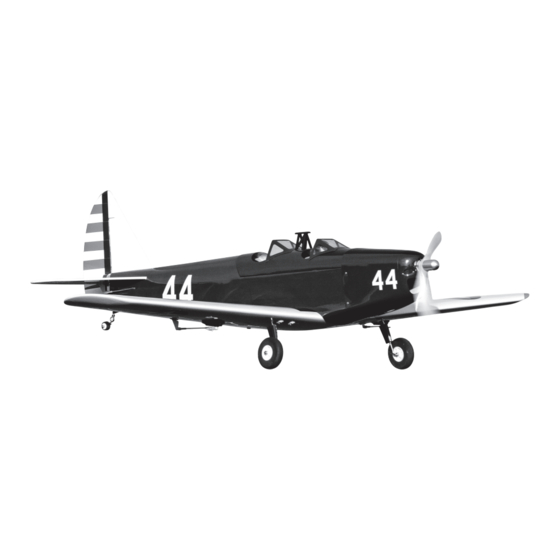
Fun Scale PT-19 PNP
Scan the QR code and select the Manuals and Support quick links from the product
page for the most up-to-date manual information.
Scannen Sie den QR-Code und wählen Sie auf der Produktseite die Quicklinks
Handbücher und Unterstützung, um die aktuellsten Informationen zu Handbücher.
Scannez le code QR et sélectionnez les liens rapides Manuals and Support sur la page
du produit pour obtenir les informations les plus récentes sur le manuel.
Scannerizzare il codice QR e selezionare i Link veloci Manuali e Supporto dalla pagina
del prodotto per le informazioni manuali più aggiornate.
HAN3180
Instruction Manual
Bedienungsanleitung
Manuel d'utilisation
Manuale di Istruzioni
Werbung
Inhaltsverzeichnis

Verwandte Anleitungen für Horizon Hobby HANGAR 9 Fun Scale PT-19 PNP


Inhaltszusammenfassung für Horizon Hobby HANGAR 9 Fun Scale PT-19 PNP
- Seite 1 Fun Scale PT-19 PNP Instruction Manual Bedienungsanleitung Manuel d’utilisation Manuale di Istruzioni Scan the QR code and select the Manuals and Support quick links from the product page for the most up-to-date manual information. Scannen Sie den QR-Code und wählen Sie auf der Produktseite die Quicklinks Handbücher und Unterstützung, um die aktuellsten Informationen zu Handbücher.
-
Seite 2: Safe Operating Recommendations
• For a computer radio, create a model memory for this particular model. of Horizon Hobby, LLC. This manual contains instructions for safety, operation and maintenance. It is essential to • Bind your transmitter and receiver, using your radio system’s instructions. -
Seite 3: Inhaltsverzeichnis
SPECIFICATIONS REPLACEMENT PARTS Part # Description in (1435 mm) HAN318001 Fuselage HAN318002 Wing Panels 537 sq in (35.65 dm2) HAN318003 Landing Gear HAN318004 Horizontal Stabilizer 46.18 in (1172 mm) HAN318005 Vertical Stabilizer HAN318006 Tailwheel Assembly 79 oz (2240 g) without battery, 96 oz (2722 g) with recommended battery HAN318007 Tail Nut Cover HAN318009... -
Seite 4: Optional Batteries For High Power (When Using 12 X 6 Propeller)
OPTIONAL BATTERIES FOR HIGH POWER (WHEN USING 12 X 6 PROPELLER) CHECKING THE AILERON SERVOS # Required Part # Description Pull the aileron servo leads through the holes in the top of the wing. SPMX40006S30 4000mAh 6S 22.2V Smart 30C; IC5 SPMX50006S30 5000mAh 6S 22.2V Smart 30C;... -
Seite 5: Landing Gear Installation
LANDING GEAR INSTALLATION Optional 10. Use a fl exible silicone adhesive to attach the landing gear Fit the landing gear wire into the wing. The landing gear will fairings to the landing gear. Use low-tack tape to hold the angle forward when installed correctly. - Seite 6 15. Flex the elevator through its range of motion a few times to 19. Slide one #4 washer on each of the threaded rods. break in the hinges. 20. Thread the 4-40 nuts on the threaded rods. 16. Remove the magnetically-retained lower fuselage cover from 21.
-
Seite 7: Receiver Installation
24. Use the three #2 x 5/16 inch sheet metal screws to secure 29. Use a straight edge or ruler to check the alignment of the the tail wheel bracket to the fuselage. Use a #1 Phillips elevator to the stabilizer. The ruler will lay fl at across both screwdriver to tighten the screws. -
Seite 8: Wing Installation
34. Apply one side of the hook and loop tape to the battery tray. FINAL ASSEMBLY Optional: Apply a thin coat of thin CA on the 39. Install the canopy hatch on the fuselage. tray using a paper towel. Allow the CA to cure before applying the hook and loop tape. -
Seite 9: Center Of Gravity
CENTER OF GRAVITY PUSHROD CONNECTIONS Elevator An important part of preparing the aircraft for fl ight is properly balancing the model. Before checking the control throws, make sure the pushrods are connected to the servo arms as shown to achieve the correct Attach the wing to the fuselage. -
Seite 10: Control Throws
CONTROL THROWS PREFLIGHT CHECKLIST • Charge the transmitter, receiver and motor batteries. Follow the instructions provided with the charger. Follow all Turn on the transmitter and receiver of your model. Check the movement of the rudder using the transmitter. manufacturer’s instructions for your electronic components. When the stick is moved to the right, the rudder should also move right. -
Seite 11: Limited Warranty
Inspection or Services any part of the Product, (iv) attempted service by anyone other than a Horizon Hobby authorized service center, (v) Product If this Product needs to be inspected or serviced and is compliant in the country you live and use the Product in, please use... -
Seite 12: Compliance Information For The European Union
Union D 22885 Barsbüttel, Germany Sales: Horizon Hobby GmbH +49 (0) 4121 2655 100 • I will not operate any model aircraft while I am under the infl uence of alcohol or any drug that could adversely affect my ability to safely control the model. -
Seite 13: Propeller
Halten Sie lose Gegenstände, die sich im Propeller verfangen können, immer vom Propeller fern. Dazu gehören lose Alle Anweisungen, Garantien und andere Begleitdokumente können von Horizon Hobby, LLC nach eigenem Ermessen Kleidung oder andere Gegenstände wie Stifte und Schraubendreher. Halten Sie Ihre Hände vom Propeller fern, da es zu geändert werden. -
Seite 14: Spmxam2100 4250-600Kv Motor
SPEZIFIKATIONEN ERSATZTEILE Teile-Nr. Beschreibung in (1435 mm) HAN318001 Rumpf HAN318002 Tragfl ächen 537 sq in (35.65 dm2) HAN318003 Fahrwerk Set HAN318004 Höhenruder 46.18 in (1173 mm) HAN318005 Seitenleitwerk HAN318006 Spornrad m. Zbh. 55 oz (1569 g) ohne Akku, 73 oz (2079 g) mit empfohlenem Akku HAN318007 Heckmutterabdeckung HAN318009... -
Seite 15: Optionale Akkus Für Hochleistung (Bei Verwendung Eines 12 X 6 Propeller)
OPTIONALE AKKUS FÜR HOCHLEISTUNG (BEI VERWENDUNG EINES 12 X 6 PROPELLER) QUERRUDER-SERVOS PRÜFEN Erforderliche Teile-Nr. Beschreibung Die Leitungen des Querruder-Servos durch die Löcher in der Anz. Oberseite des Flügels führen. SPMX40006S30 4000 mAh 6S 22,2V Smart LiPo 30C; IC5 SPMX50006S30 5000 mAh 6S 22,2V Smart LiPo 30C; IC5 ERFORDERLICHE WERKZEUGE UND KLEBSTOFFE Querruder-Servo mit dem Empfänger verbinden. -
Seite 16: Montage Des Fahrwerks
MONTAGE DES FAHRWERKS Optional 11. Mit einem fl exiblen Silikonklebstoff die Das Kabel des Fahrwerks in den Flügel einpassen. Wenn es Fahrwerkverkleidungen am Fahrwerk befestigen. Mit einem korrekt montiert ist, neigt sich das Fahrwerk nach vorne. Das Klebeband mit geringer Klebekraft die Fahrwerkverkleidungen Kabel wird bündig mit dem Flügelboden abschließen wenn es in Position halten, bis der Klebstoff vollständig ausgehärtet ist. - Seite 17 16. Das Höhenruder einige Male durch seinen Bewegungsradius 21. Eine Nr. 4 Unterlegscheibe auf jede der Gewindestangen biegen, um die Aufhängungen einzufahren. schieben. 22. Die 4-40 Muttern auf die Gewindestange drehen. 18. Die magnetisch gesicherte untere Rumpfabdeckung vom 23. Mit einem 6 mm (1/4 Zoll) Steckschlüssel die Muttern Rumpf entfernen.
-
Seite 18: Montage Des Empfängers
26. Mithilfe von drei #2 x 7,5 mm (5/16 Zoll) Metallschrauben 31. Mit einem Geodreieck oder Lineal die Ausrichtung des die Spornradhalterung am Rumpf befestigen. Mit einem Höhenruders auf dem Stabilisator prüfen. Das Lineal liegt Kreuzschlitzschraubendreher Nr. 1 die Schrauben festziehen. nach korrekter Ausrichtung fl ach über beiden. Den Gabelkopf bei Bedarf an das Gestänge anpassen, um das Höhenruder auszurichten. -
Seite 19: Montage Der Tragfl Äche
36. Eine Seite des Klettbands an der Akkuhalterung befestigen. ABSCHLIESSENDE MONTAGE Optional: Eine dünne Schicht CA-Klebstoff mithilfe eines 41. Die Batterieabdeckung auf dem Rumpf montieren. Papiertuchs auf die Halterung auftragen. Den CA-Klebstoff aushärten lassen, ehe das Klettband angebracht wird. ... -
Seite 20: Der Schwerpunkt
DER SCHWERPUNKT GESTÄNGEANSCHLÜSSE Höhenruder Ein wichtiger Teil bei der Vorbereitung des Flugzeugs für den Flug ist das ordnungsgemäße Ausbalancieren des Vor Überprüfung des Ruderausschlags sicherstellen, dass die Modells. Gestänge wie abgebildet an den Servoarmen angeschlossen sind, um einen korrekten Ruderausschlag zu erreichen. Die Tragfl... -
Seite 21: Ruderausschlag
RUDERAUSSCHLAG VORFLUGKONTROLLE • Akkus für Sender, Empfänger und Motor aufl aden. Die dem Ladegerät beigelegten Anweisungen befolgen. Die Den Sender und Empfänger des Modells einschalten. Die Bewegung des Seitenruders mit dem Empfänger prüfen. Anweisungen des Herstellers der elektrischen Bauteile befolgen. Wird der Hebel nach rechts bewegt, sollte sich auch das Seitenruder nach rechts bewegen. -
Seite 22: Garantie Und Service Informationen
Es ist unabdingbar, diese Hinweise vor der ersten Inbetriebnahme zu lesen und zu verstehen. Nur so kann der falsche Garantiezeitraum Exklusive Garantie Horizon Hobby LLC (Horizon) garantiert, dass dasgekaufte Produkt frei von Material- und Umgang verhindert und Unfälle mit Verletzungen und Beschädigungen vermieden werden. -
Seite 23: Garantie Und Service Kontaktinformationen
D 22885 Barsbüttel, Germany service@horizonhobby.de Horizon Hobby GmbH WEEE-HINWEIS: EU Konformitätserklärung Hiermit erklärt Horizon Hobby, LLC, dass das Dieses Gerät ist gemäß der Europäischen Gerät den folgenden Richtlinien entspricht: Richtlinie 2012/19/EU über Elektro- und Elektronik-Altgeräte (WEEE) gekennzeichnet. Dieses Symbol weist Öko-Design-Richtlinie 1275/2008;... -
Seite 24: Avertissements Relatifs À La Sécurité
• Si un élément est endommagé, contactez votre revendeur. avec des composants incompatibles hors des instructions fournies par Horizon Hobby, LLC. Ce manuel comporte des instructions relatives à la sécurité, au fonctionnement et à l’entretien. Il est capital de lire et de respecter la totalité... -
Seite 25: Han318014 Han318015
SPÉCIFICATIONS PIÈCES DE RECHANGE Référence Description in (1435 mm) HAN318001 Fuselage HAN318002 Panneaux d’aile 537 sq in (35.65 dm2) HAN318003 Train d’atterrissage HAN318004 Stabilisateur 46.18 in (1172 mm) HAN318005 Stabilisateur vertical HAN318006 Assemblage de roulette de queue 1569 g (55 oz) sans batterie, 2079 g (73 oz) avec la batterie recommandée HAN318007 Cache d’écrou de queue HAN318009... -
Seite 26: Batteries En Option Pour Haute Puissance (Pour L'hélice 12 X 6)
BATTERIES EN OPTION POUR HAUTE PUISSANCE (POUR L’HÉLICE 12 X 6) VÉRIFICATION DES SERVOS D’AILERON Nombre Référence Description Faites passer les fi ls du servo d’aileron par les trous en haut requis de l’aile. SPMX40006S30 4000mAh 6S 22.2V Smart 30C; IC5 SPMX50006S50 5000mAh 6S 22.2V Smart 50C;... -
Seite 27: Installation Du Train D'atterrissage
INSTALLATION DU TRAIN D’ATTERRISSAGE Facultatif 11. Utilisez une colle silicone fl exible pour fi xer les carénages Placez le fi l du train d’atterrissage dans l’aile. Le train du train d’atterrissage sur le train d’atterrissage. Utilisez d’atterrissage penche vers l’avant s’il est installé du ruban adhésif à... - Seite 28 16. Pliez plusieurs fois la profondeur dans une amplitude de 21. Faites glisser un écrou n 4 sur chacune des tiges fi letées. mouvements pour rompre les charnières. 22. Vissez les écrous 4-40 sur les tiges fi letées. 18. Retirez la trappe de fuselage inférieure sécurisée 23.
-
Seite 29: Installation Du Récepteur
26. Utilisez les trois vis à tôle n 2 x 5/16 po pour fi xer le support 31. Utilisez un bord rectiligne ou une règle pour vérifi er de la roue de queue au fuselage. Utilisez un tournevis l’alignement de la profondeur avec le stabilisateur. La règle cruciforme n 1 pour serrer les vis. -
Seite 30: Installation De L'aile
36. Appliquez un côté de la bande scratch sur la tablette de la ASSEMBLAGE FINAL batterie. 41. Installez la trappe de la verrière sur le fuselage. Facultatif : Appliquez une fine couche de CA fine sur la tablette à l’aide de papier absorbant. Laissez sécher la CA avant d’appliquer la bande scratch. -
Seite 31: Centre De Gravité
CENTRE DE GRAVITÉ CONNEXIONS DES BARRES DE LIAISON Gouverne de profondeur Une des étapes importantes de la préparation d’un modèle est son équilibrage. Avant de vérifi er les coudes de commande, assurez-vous que les barres de liaison sont connectées aux bras de servo, comme illustré, afi... -
Seite 32: Débattements
DÉBATTEMENTS CHECKLIST D’AVANT VOL • Chargez l’émetteur, le récepteur et les batteries du moteur. Suivez les instructions fournies avec le chargeur. Suivez Mettez l’émetteur et le récepteur de votre maquette sous tension. Vérifi ez le mouvement de la dérive à l’aide toutes les instructions du fabricant pour vos composants électroniques. -
Seite 33: Garantie Et Réparations
L’incapacité à utiliser le produit de manière sure et raisonnable Garantie exclusive - Horizon Hobby, LLC (Horizon) garantit que le Produit acheté (le « Produit ») sera exempt de défauts peut provoquer des blessures et des dégâts matériels conséquents. Ce produit n’est pas destiné à être utilisé par des matériels et de fabrication à... -
Seite 34: Coordonnées De Garantie Et Réparations
INFORMATIONS DE CONFORMITÉ POUR DIRECTIVE DEEE L’étiquette de cet appareil respecte la L’UNION EUROPÉENNE directive européenne 2012/19/UE en Par la présente, Horizon Hobby, LLC déclare matière de déchets des équipements que cet appareil est conforme aux directives électriques et électroniques (DEEE). Cette suivantes : étiquette indique que ce produit ne doit... -
Seite 35: Avvertimenti E Precauzioni Per La Sicurezza
Non usare componenti non compatibili • Caricare il trasmettitore e la batteria di volo. o alterare il prodotto in nessuna maniera al di fuori delle istruzioni fornite da Horizon Hobby, LLC. Questo manuale • Centrare stick e trim sul trasmettitore. -
Seite 36: Spma3050 Spmar637T Spmr6775 Spmx50004S30
SPECIFICHE PEZZI DI RICAMBIO Pezzo # Descrizione in (1435 mm) HAN318001 Fusoliera HAN318002 Pannelli alari 537 sq in (35.65 dm2) HAN318003 Set del carrello di atterraggio HAN318004 Stabilizzatore 46.18 in (1172 mm) HAN318005 Stabilizzatore verticale HAN318006 Gruppo del ruotino di coda 1569 g senza batteria, 2079 g con la batteria consigliata HAN318007 Coperchio del dado di coda... -
Seite 37: Batterie Opzionali Per Grande Potenza (Per Elica 12 X 6)
BATTERIE OPZIONALI PER GRANDE POTENZA (PER ELICA 12 X 6) CONTROLLO DEI SERVO DEGLI ALETTONI # richiesto Parte # Descrizione Tirare i fi li dei servo degli alettoni facendoli passare nei fori sulla parte superiore dell’ala. SPMX40006S30 4000mAh 6S 22.2V Smart 30C; IC5 SPMX50006S50 5000mAh 6S 22.2V Smart 50C;... -
Seite 38: Montaggio Del Carrello Di Atterraggio
MONTAGGIO DEL CARRELLO DI ATTERRAGGIO Opzionale 11. Usare un adesivo siliconico fl essibile per attaccare le Inserire il fi lo del carrello nell’ala. Il carrello di atterraggio carenature al carrello di atterraggio. Utilizzare un nastro a risulta leggermente inclinato in avanti quando installato bassa adesione per tenere le carenature in posizione fi... - Seite 39 16. Flettere più volte l’equilibratore per tutta la sua ampiezza di 21. Far scorrere una rondella #4 su ciascuna delle aste fi lettate. movimento per rodare le cerniere. 22. Avvitare i dadi 4-40 sulle aste fi lettate. 18. Rimuovere dalla fusoliera il coperchio inferiore trattenuto 23.
-
Seite 40: Montaggio Del Ricevitore
26. Fissare la staffa del ruotino di coda alla fusoliera con tre viti 31. Utilizzare un bordo dritto o una squadretta per controllare per lamiera #2 x 5/16". Utilizzare un cacciavite a croce #1 per l’allineamento tra equilibratore e stabilizzatore. Il righello serrare le viti. -
Seite 41: Montaggio Dell'ala
36. Applicare un lato della fascetta a strappo sul supporto della MONTAGGIO FINALE batteria. 41. Montare il tettuccio sulla fusoliera. Opzionale: applicare uno strato sottile di colla cianoacrilica sul vassoio usando un tovagliolo di carta. Lasciare indurire la colla prima di applicare la fascetta a strappo. ... -
Seite 42: Baricentro
BARICENTRO COLLEGAMENTO DELLE ASTE DI COMANDO Equilibratore Una parte molto importante nella preparazione del modello riguarda il suo bilanciamento. Prima di controllare le corse dei comandi, assicurarsi che le aste di comando siano collegate ai bracci del servo come mostrato per Fissare le ali alla fusoliera. -
Seite 43: Corse Dei Comandi
CORSE DEI COMANDI LISTA DEI CONTROLLI PRIMA DEL VOLO • Caricare la trasmittente, il ricevitore e le batterie del motore. Seguire eventuali istruzioni fornite con il caricabatterie. Accendere la trasmittente e la ricevente del modello. Controllare il movimento del timone con il radiocomando. Seguire tutte le istruzioni del produttore relative ai componenti elettronici. -
Seite 44: Garanzia
Se il prodotto non verrà Garanzia esclusiva - Horizon Hobby, LLC (Horizon) garantisce che il prodotto acquistato (il “Prodotto”) sarà privo di manipolato in maniera sicura e responsabile potrebbero risultare delle lesioni, dei gravi danni a persone, al prodotto o difetti relativi ai materiali e di eventuali errori di montaggio alla data di acquisto. -
Seite 45: Contatti Per La Garanzia E L'assistenza
Horizon Hobby GmbH Dichiarazione di Conformità EU AVVISO RAEE: Con la presente, Horizon Hobby, LLC dichiara Questo dispositivo è marcato ai sensi della che il dispositivo è conforme a quanto segue: Direttiva europea 2012/19/UE riguardante i rifi uti di apparecchiature elettriche ed elettroniche (RAEE). - Seite 46 BUILDING AND FLYING NOTES • NOTIZEN ZUM AUFBAU UND FLIEGEN • REMARQUES SUR LE MONTAGE ET LE PILOTAGE • NOTE DI MONTAGGIO E DI VOLO...
- Seite 47 BUILDING AND FLYING NOTES • NOTIZEN ZUM AUFBAU UND FLIEGEN • REMARQUES SUR LE MONTAGE ET LE PILOTAGE • NOTE DI MONTAGGIO E DI VOLO...
- Seite 48 © 2022 Horizon Hobby, LLC. Hangar 9, SAFE, AS3X, DSMX, Avian, IC3, IC5 and the Horizon Hobby logo are trademarks or registered trademarks of Horizon Hobby, LLC. The Spektrum trademark is used with permission of Bachmann Industries, Inc. All other trademarks, service marks and logos are the property of their respective owners.