Seite 7
Reparaturen ........................... 38 Prüfungspflicht ..........................38 Hinweis zum Typenschild ....................... 39 Hinweis zur Vermietung/Verleihung von PROBST-Geräten ............39 Entsorgung / Recycling von Geräten und Maschinen ..............39 Schmieranweisung (Parallel-Gleitführungen) ................... 40 Änderungen gegenüber den Angaben und Abbildungen in der Betriebsanleitung sind vorbehalten.
Seite 8
DIN EN ISO 13857 Sicherheit von Maschinen - Sicherheitsabstände gegen das Erreichen von Gefährdungsbereichen mit den oberen und unteren Gliedmaßen Dokumentationsbevollmächtigter: Name: Jean Holderied Anschrift: Probst GmbH; Gottlieb-Daimler-Straße 6; 71729 Erdmannhausen, Germany Unterschrift, Angaben zum Unterzeichner: Erdmannhausen, 16.05.2024..............(Eric Wilhelm, Geschäftsführer) 51400034...
Seite 9
Sicherheit Sicherheit Definition Fachpersonal/ Sachkundiger Installations-, Wartungs- und Reparaturarbeiten an diesem Gerät dürfen nur von Fachpersonal oder Sachkundigen durchgeführt werden! Fachpersonal oder Sachkundige müssen für die folgenden Bereiche, für Mechanik • soweit es für dieses Gerät zutrifft, die notwendigen beruflichen Kenntnisse für Hydraulik •...
Seite 10
Sicherheit Sicherheitskennzeichnung VERBOTSZEICHEN Symbol Bestell- Bedeutung Größe: Nr.: 29040210 30 mm Niemals unter schwebende Last treten. Lebensgefahr! 29040209 50 mm 29040204 80 mm Achtung Quetschgefahr! Nur an Handgriffen anfassen. 29040367 205x30 mm WARNZEICHEN Symbol Bedeutung Bestell- Größe: Nr.: 29040221 30 mm Quetschgefahr der Hände.
Seite 11
Sicherheit Persönliche Sicherheitsmaßnahmen • Jeder Bediener muss die Bedienungsanleitung für das Gerät mit den Sicherheitsvorschriften gelesen und verstanden haben. Das Gerät und alle übergeordneten Geräte in/an die das Gerät eingebaut ist, dürfen nur von dafür • beauftragten und qualifizierten Personen betrieben werden. Es dürfen nur Geräte mit Handgriffen manuell geführt werden.
Seite 12
Sicherheit 2.8.2 Hydraulik • Alle Hydraulikleitungen und Anschlüsse vor jedem Arbeitseinsatz auf Dichtigkeit prüfen. Defekte Teile in drucklosem Zustand von Fachpersonal austauschen lassen. Vor dem Öffnen von Hydraulikanschlüssen ist das Umfeld gründlich zu reinigen. • Bei Arbeiten an der Hydraulikanlage ist auf Sauberkeit zu achten. •...
Seite 13
Sicherheit 2.9.2 Sicherheit im Verlegebetrieb Das Gerät nur an dessen Handgriffen in Position ziehen! • Der Bediener muss das Gerät während des gesamten Transportes bis zum Absetzen ungehindert • beobachten können Steinlagen nie außermittig aufnehmen, Kipp- und Verletzungsgefahr! • Steinpaketlagen vorsichtig aufsetzen •...
Seite 14
Sicherheit 2.9.3 Ermittlung der greiftechnischen Qualität Zum sicheren und reibungslosen Betrieb der Anlage/des Gerätes ist es unbedingt erforderlich, dass die Qualität der Steinlagen anhand der folgenden Vorgehensweise durchgeführt wird.: Die Anzahl der zu greifenden Steine wird übereinander Hauptspannungs- gestapelt, wobei die Steine auf der richtung Hauptspannungsrichtung stehen, d.h.
Seite 15
Seitens des Trägergerätes (Baggers), sind zwei voneinander getrennte hydraulische Steuerkreise zur Betätigung der HVZ-ECO erforderlich. • Mit diesem Gerät HVZ-ECO kann jeweils eine Verbundsteinpaket-Lage abgegriffen und verlegt werden. Die Tragfähigkeiten und Nennweiten der hydraulische Verlegezange HVZ-ECO dürfen nicht überschritten werden.
Seite 16
Allgemeines Verbundsteinformen 1.) Nachstehend abgebildete Verbundsteinformen 1 – 20 sind u. a. für maschinelle Verlegung geeignet. Es können auch andere Steinformen verlegt werden. Voraussetzung ist, dass die Steine in maschinenverlegegerechter Formation paketiert sind. 2.) Die Verbundsteinformen 16-20 sind mit Positionierungsadapter PA (4140.0003) zur maschinellen Verlegung geeignet.
Seite 17
Allgemeines NICHT ERLAUBTE TÄTIGKEITEN: Eigenmächtige Umbauten am Gerät oder der Einsatz von eventuell selbstgebauten Zusatzvorrichtungen gefährden Leib und Leben und sind deshalb grundsätzlich verboten!! Tragfähigkeiten (WLL) des Gerätes dürfen nicht überschritten und Nennweiten/Greifbereiche dürfen nicht überschritten bzw. unterschritten werden. Alle nicht bestimmungsgemäßen Transporte mit dem Gerät sind strengstens untersagt: •...
Seite 18
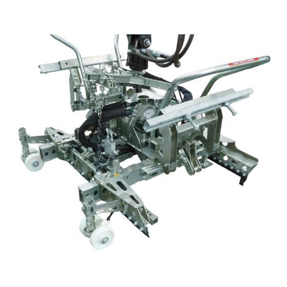
Allgemeines Übersicht und Aufbau Bedienbügel Seitenspannung Drehkopf (360°) Greiftiefeneinstellung Einstellung Absetzrollen Planumseitige Greifwange Maschinenseitige Greifwange Stahllamellen Technische Daten Die genauen technischen Daten (wie z.B. Tragfähigkeit, Eigengewicht, etc.) sind dem Typenschild zu entnehmen. 51400034 14 / 40...
Seite 19
Bauteilen zusammenstoßen kann. Dies ist durch geeignete Positionierung des Gerätes und angepasster Fahrweise möglichst zu vermeiden. Daraus resultierende Schäden werden nicht im Rahmen der Gewährleistung reguliert. Die mechanische Verbindung der HVZ-ECO mit dem Trägergerät (Bagger) erfolgt über die eine Baggeraufhängung (UBA, bzw. Lehnhofadapter). Baggeraufhängung Lehnhofadapter...
Seite 20
Installation Baggeraufhängung UBA Es muss eine gesicherte Verbindung (Sicherungsschraube mit Stopp-Mutter) zwischen Drehkopf und Baggeraufhängung hergestellt werden. Baggeraufhängung (UBA) Sicherungsschraube mit Stopp-Mutter Pendelbremse Drehkopf Einstellung der Sicherungsmutter hat Einfluss auf die Bewegungsgeschwindigkeit der Pendelbremse. 4.1.1 Einstecktaschen (optional) Um eine sichere Verbindung zwischen dem Gabelstapler und der Einstecktasche (3) herzustellen, fährt man mit den Gabelstapler-Zinken (1) in die Einstecktasche (3) hinein.
Seite 21
Installation Hydraulischer Anbau Zum Anschluss der HVZ-ECO an das Trägergerät werden zwei voneinander getrennte Hydrauliksteuerkreise benötigt. Der Anschluss der Hydraulikschläuche erfolgt am hydraulischen Drehkopf. Durch Lösen der beiden Arretierungsschrauben kann die Öffnungsweite zwischen der Steckbolzenaufnahme, bei Bedarf verändert werden (). Hierzu beide Steckbolzenaufnahmen herausnehmen, um 180° verdrehen (siehe Pfeile), wieder einführen und mit Arretierungsschraube wieder sichern.
Seite 22
Installation Einstellung „Bypass-Ventil“ Die Nachrüstung eines „Bypass-Ventiles“ (siehe ) am hydraulischen Drehkopf ist erforderlich, um bei Trägergeräten (Baggern) mit Hydrauliköl-Volumenströmen > 40 l/min, einen Teil des Ölstromes gleich wieder in den Rücklauf des Trägergerätes zurück zu leiten. Die optimale Einstellung muss während des laufenden Betriebes der Verlegezange ermittelt werden. ACHTUNG: Sollte die Verschiebekraft der Seitenspannung zu gering sein, dann ist das Bypass-Ventil aller Wahrscheinlichkeit nach zu weit geöffnet! In diesem Fall muss das Bypass-Ventil etwas zu gedreht...
Seite 23
Einstellungen Einstellungen Allgemein Alle Einstellarbeiten dürfen nur bei stillgelegtem Gerät vorgenommen werden! Vorsicht bei der Einstellung des Greifbereiches. Verletzungsgefahr der Hände! Schutzhandschuhe verwenden. → Greiftiefeneinstellung 5.2.1 Planumseite Greiftiefeneinstellung (Planumseite) ist so Bei extrem großen Steinlagen empfiehlt es sich die einzustellen, dass die Stahllamellen sich im unteren Greiftiefeneinstellung etwas niedriger einzustellen, so ⅓...
Seite 24
Einstellungen Federriegel um 180 verdrehen und in Kerbe Abstand ca. auf 100 mm -150 mm Mitte einrasten. Greiftiefeneinstellung von der Außenkante der Greiftiefeneinstellung entsprechend verschieben u. Steinlage einstellen. Federriegel wieder um 180 verdrehen und einrasten. 100 – 150 mm Bild 5 3,94 –...
Seite 25
Einstellungen 5.2.2 Maschinenseite Greiftiefeneinstellung (Maschinenseite) ist so Bei extrem großen Steinlagen empfiehlt es sich die einzustellen, dass die Stahllamellen sich auf der ½ Greiftiefeneinstellung etwas niedriger einzustellen, so der Steinlage (siehe Bild 8) befinden. dass die Stahllamellen im untersten Bereich der Beispiel: bei Steinlagenbreite 800 mm Steinlage greifen.
Seite 26
Einstellungen Einstellung Absetzrollen Zum Einstellen der Absetzrollen, beide Kurbeln an Höhe der beider Absetzrollen genau gleich einstellen den Absetzrollen nach oben stellen. (Kurbeln). Abstand zwischen Lamellen zur Steinlangenunterkante ungefähr 50 mm (siehe Darstellung A) Bild 12 Bild 11 Beide Kurbeln an den Absetzrollen wieder nach unten stellen und sichern.
Seite 27
Einstellungen Einstellung Hauptspannung 5.4.1 Maschinenseite Einstellung „C“ der Hauptspannung laut Hauptspannung auf Position ziehen (). Einstellaufkleber am Gerät (Maschinenseite) Federriegel wieder um 180 verdrehen und einrasten. entsprechend der Steinlagenlänge. Beide Federriegel () um 180 verdrehen und in Kerbe einrasten lassen. Maschinenseite Maschinenseite Bild 15...
Seite 28
Planumseite Bild 19 Das Gerät (HVZ-ECO) ist optimal eingestellt, wenn beim Greifvorgang bei geöffneter Zange, die Stahl- Lamellen (Maschinenseite) direkt an der Steinlage anliegen u. die Stahl-Lamellen (Planumseite) etwa einen Abstand zur Steinlage von 100 -150 mm haben (Bild 20).
Seite 29
Einstellungen Abdrückschiene Ab einer Steinlagenbreite über 1000 mm sollte die einstellbare Abdrückschiene (max. 1200 mm) ausgefahren werden. Federstecker herausziehen u. gleichzeitig etwas verdrehen. Dann Federstecker wieder los lassen. Abdrückschiene entsprechend verschieben, Federstecker etwas herausziehen u. gleichzeitig etwas verdrehen bis er wieder in Bohrung einrastet. Bild 21 Einstellung Feder-Stahllamellen Die Stahllamellen sollten nicht seitlich über die Steinkontur hervorstehen, da sie sonst beim Ablegevorgang...
Seite 30
Einstellungen Veränderung der Backenbreite Zum optimalen Greifen der Steinlagen, besteht die Möglichkeit die Backenbreite entsprechend zu verändern. Grund: da oftmals die jeweils außen liegenden Feder-Stahllamellen (Bild 22.1) beim Greifvorgang an der Steinlage außen etwas überstehen und somit das Anlegen an eine bereits verlegte Steinlage eventuell erschweren.
Seite 31
Einstellungen Bild 26 Bild 25 Höhe der Seitenspannung 3) Seitenspannung auf entsprechende Position Höhe der Seitenspannung auf Mitte der Steinlage einstellen (). einstellen: 4) Beide Schrauben wieder einstecken und mit 1) Seitenspannung öffnen. Muttern sichern. 2) Mutter und Schrauben der Seitenspannung 5) Seitenspannung schließen und kontrollieren, entfernen ().
Seite 32
Einstellungen 5.10 Gewichtsausgleich einstellen Nach erfolgter Einstellung der Haupt- u. Seitenspannung am Gerät ist darauf zu achten, dass die HVZ-ECO waagrecht zur Arbeitsfläche ausgerichtet ist, gegebenenfalls leicht geneigt zur Maschinenseite (Absetzrollen). Klappstecker (C) oben an der Kettenaufhängung (A) entfernen und beide Einstellketten (B) jeweils auf die gleiche Länge einstellen (siehe Bild 30).
Seite 33
Klammerbetätigung und Drehkopfbetätigung vertraut. Prägen Sie sich insbesondere ein, welche Hebelfunktion ein Öffnen der Klammer (meist Betätigung des hydraulischen Steuerhebels vom Bediener weg) bewirkt, damit Sie nicht aus Versehen diese Funktion bei angehobener HVZ-ECO mit gegriffener Steinlage betätigen und so die Steinlage aus der Klammer herausfallen lassen.
Seite 34
Bedienung 6.2.2 Programm 2 (ohne Nebenspannung) Zum Abgreifen und Verlegen von Steinlagen unter ausschließlicher Verwendung der Hauptspannung. Dieses Programm wird zum Beispiel dann verwendet, wenn bei der Verlegung die Position der Verlegezange zur Steinlage bei jedem zweiten Verlegezyklus um 180 Grad verdreht werden muss. Um Programm 2 zu nutzen, muss der Abstellhahn (unterhalb der Zangenaufhängung) von waagrechter Stellung (Durchflussrichtung) in senkrechte Stellung (Sperrstellung) gestellt werden (siehe Abbildungen darunter).
Seite 35
Bedienung Hinweise zur normgerechten Verlegung von Betonpflastersteinen • Es wird davon ausgegangen, dass die zur Verlegung kommenden Betonstein- Verlegeinheiten eine normgerechte, gleichförmiges Verlegemuster erlauben. Es wird davon ausgegangen, dass die zur Verlegung kommenden Betonpflastersteine mit • sogenannten Abstandshilfen mit mindestens 2,5 mm Dicke versehen sind. Durch den Einbau der Technologie der Abdrückvorrichtung ADV sind die optimalen Voraussetzungen •...
Seite 36
• Die Klammer absenken, bis die Auflageteller der Klammer die Steinoberflächen berühren. Danach nicht weiter absenken! Die Traverse darf keinesfalls den HVZ-ECO Aufsatz berühren und somit Druck von oben auf die Klammer ausgeübt werden (durch den Ausleger des Trägergerätes). 51400034...
Seite 37
Bedienung Hydraulischen Steuerhebel auf „Position 1“ betätigen, • Bild 2 Pos 2 Pos. 0 Pos.1 so lange auf dieser Position halten, bis folgende Bewegungen abgelaufen sind: 1) Hauptspannung schließt 2) Hauptspannung öffnet geringfügig 3) Nebenspannung schließt 4) Hauptspannung schließt 5) Nebenspannung öffnet Erklärung: Positionen Steuerhebel Pos.1: Greifen, Ablegen, Reset •...
Seite 38
Bedienung Allgemeine Hinweise zur normgerechten Verlegung • Nach dem Ablegevorgang müssen die Steine der frisch verlegten Steinlage, am besten nur mit den Schuhen des Ausrichters, geringfügig zum Planum hin auseinandergetrieben werden. Nur so lässt sich eine normgerechte Fuge in der Größe 3 bis 5 mm erzielen! Ist vor dem Beginn einer maschinellen Verlegefläche eine Handverlegeanfang erforderlich, müssen bei der Handverlegung die Rastermaße der Verlegeeinheit eingehalten werden.
Seite 39
Wartung und Pflege Wartung und Pflege Wartung Um eine einwandfreie Funktion, Betriebssicherheit und Lebensdauer des Gerätes zu gewährleisten, sind die in der Tabelle aufgeführten Wartungsarbeiten nach Ablauf der angegebenen Fristen durchzuführen. Es dürfen nur Original-Ersatzteile verwendet werden, ansonsten erlischt die Gewährleistung. Alle Arbeiten dürfen nur im drucklosen, stromlosen und beim stillgelegten Zustand des Gerätes erfolgen! Bei allen Arbeiten muss sichergestellt sein, dass sich das Gerät nicht unbeabsichtigt schließen kann.
Seite 40
Wartung und Pflege 7.1.2 Hydraulik WARTUNGSFRIST Auszuführende Arbeiten Erstinspektion nach • Sämtliche Hydraulikverschraubungen kontrollieren bzw. nachziehen 25 Betriebsstunden (darf nur von einem Sachkundigen durchgeführt werden). Erstinspektion nach Hydraulikflüssigkeit austauschen (empfohlenes Hydrauliköl: HLP 46 nach DIN • 50 Betriebsstunden 51524 – 51535). •...
Seite 41
Wartung und Pflege Störungsbeseitigung STÖRUNG URSACHE BEHEBUNG Steinlage bricht nach unten aus Hauptspannung ist falsch Einstellung nach • • eingestellt (200 mm Hub) Einstellaufkleber überprüfen Greiftiefe etwas tiefer einstellen, • Steinlage ist extrem groß • dass Stahllamellen im unteren Bereich der Steinlage greifen. •...
Seite 42
Die dementsprechenden gesetzlichen Bestimmungen u. die der Konformitätserklärung sind zu • beachten! • Die Durchführung der Sachkundigenprüfung kann auch durch den Hersteller Probst GmbH erfolgen. Kontaktieren Sie uns unter: service@probst-handling.de Wir empfehlen, nach durchgeführter Prüfung und Mängelbeseitigung des Gerätes die Prüfplakette •...
Seite 43
(z.B. Kran, Kettenzug, Gabelstapler, Bagger...) mit zu berücksichtigen. Beispiel: Hinweis zur Vermietung/Verleihung von PROBST-Geräten Bei jeder Verleihung/Vermietung von PROBST-Geräten muss unbedingt die dazu gehörige Original- Betriebsanleitung mitgeliefert werden (bei Abweichung der Sprache des jeweiligen Benutzerlandes, ist zusätzlich die jeweilige Übersetzung der Original-Betriebsanleitung mit zuliefern)! Entsorgung / Recycling von Geräten und Maschinen...
Seite 45
Anleitung zur Einstellung der hydraulischen Setzzange HVZ-ECO Zange & Zubehör Version A Version B Die Steinschicht wird nicht Die Steinschicht wird nicht verschoben. verschoben. Muss mit einer Zange bewegt Muss so mit einer Zange werden angebracht werden. 1200 mm + Halbstein = 1300 mm...
Seite 46
Einstellen der Hauptspannung (für Version A + B) *Siehe die Bilder Einstellen der Version A 800*= 400 mm Seitenspannung Seite 1 (für Version A + B) Version B Version A 1200 mm 1300 mm Bilder ansehen Version A + 100mm = 500mm Seite 1...
Seite 47
Montage der Montage von Halfeneisen Positionsadapter (für Version A + B) (nur für Version A) kürzen, oder eine passende Länge 2 x (auf beiden Seiten) bestellen versetzt ✓ Seite Seite...
Seite 48
Einstellen der Greifhöhe Einstellung der Höhe (für Version A + B) (für Version A + B) ü ü in der Mitte Abdrückvorrichtung (A + B) ü ü in der Mitte Absetzrollen (A + B) 2 - 4 mm im unteren Bereich Dritte...
Seite 49
2. Die Formen von Kompositstein 16-20 sind für das mechanische Anbringen mit dem Positionierungsadapter PA geeignet. 3. Die Formen 21-25 für Verbundpflaster sind durch einen speziellen Adapter für die maschinelle Verlegung geeignet. Probst GmbH - Gottlieb-Daimler-Str. 6 - 71729Erdmannhausen - Tel. +49 3309-07144 - Fax +49 3309-50 7144 - info@probst-handling.de...
Seite 50
(durch eine autorisierte Fachwerkstatt)! Nach jeder erfolgten Durchführung eines Wartungsintervalls muss unverzüglich dieser Wartungsnachweis (mit Unterschrift u. Stempel) an uns übermittelt werden. per E-Mail an: service@probst-handling.de / per Fax oder Post Betreiber: _ _ _ _ _ _ _ _ _ _ _ _ _ Gerätetyp:...
Seite 53
HVZ-ECO Operating Instructions 51400034 Translation of original operating instructions...
Seite 54
Contents Contents EC-Declaration of Conformity / UKCA-Declaration of Conformity ............ 4 Safety ............................... 5 Definition skilled worker / specialist ....................5 Explanation of basic concepts ......................5 Safety symbols ..........................5 Safety labeling ..........................6 Personal safety requirements ......................7 Protective equipment ........................
Seite 55
Repairs ............................38 Safety procedures .......................... 38 Hints to the type plate ........................39 Hints to the renting/leasing of PROBST devices ................39 Disposal / recycling of devices and machines .................. 39 Lubrication instructions (parallel-slide bearing guides) ..............40 We hereby reserve the right to make changes to the information and illustrations in the operating instructions.
Seite 56
Address: Probst GmbH; Gottlieb-Daimler-Straße 6; 71729 Erdmannhausen, Germany Authorized person for UK-documentation: Name: Nigel Hughes Address: Probst Ltd ; Unit 2 Fletcher House; Stafford Park 17; Telford Shropshire TF3 3DG, United Kingdom Signature, information to the subscriber: Erdmannhausen, 16.05.2024................(Eric Wilhelm, Managing Director)
Seite 57
Safety Safety Definition skilled worker / specialist Only skilled workers or specialists are allowed to carry out the installation-, maintenance-, and repair work on this device! Skilled workers or specialists must have for the following points (if it applies • for mechanic for this device), the necessary professional knowledge.
Seite 58
Safety Safety labeling PROHIBITION SIGN Icon Meaning Order no: Size: 29040210 30 mm Never step under a suspended load. Danger to life! 29040209 50 mm 29040204 80 mm Caution: Danger of crushing! Only touch the handles. 29040367 205x30 mm WARNING SIGN Icon Meaning Order no:...
Seite 59
Safety Personal safety requirements Each operator must have read and understood the operating instructions (and all safety instructions). Only qualified, authorized personal is allowed to operate the device and all devices which are connected (lifting device/carrier). The manual guiding is only allowed for devices with handles. Otherwise there is a risk of injury to the hands! Protective equipment Protective clothing...
Seite 60
Safety 2.8.2 Hydraulic • Check all hydraulic hoses and connection for tightness before every operation. Only experts are allowed to replace faulty parts (depressurized). Ensure a clean working environment before opening the hydraulic connection. • When working on the hydraulic system, ensure cleanliness. •...
Seite 61
Safety 2.9.2 Safety at installation work The manual guiding of is only allowed for devices with handles! • The load must always be in the range of vision of the operator, during the transporting and laying • operation. • Do not lift any components off-centre, because that could fall down •...
Seite 62
Safety 2.9.3 Check on the gripping quality of certain layers of paving stones For the secure function of the automatic cuber/the device the gripping quality of certain layers of paving stones has to be checked as follows: Take the number of blocks you want to grip. The blocks main gripper in main gripper direction have to face the ground.
Seite 63
Two separate hydraulic control circuits are required on the carrier (excavator) to operate the HVZ-ECO. • This HVZ-ECO device can be used to pick up and lay one layer of interlocking blocks at a time. • The load-bearing capacities and nominal widths of the HVZ-ECO hydraulic laying clamp must not be exceeded.
Seite 64
General Stone formations 1.) The stone formations 1 – 20 shown below are suitable among others for mechanical installation. Other stone formations can also be laid by machines as long as the stones are packed in the correct formation ready for the machine to lay them.
Seite 65
General NOT ALLOWED ACTIVITIES: Unauthorized alterations of the device and the use of any self-made additional equipment could cause danger and are therefore forbidden! Carrying capacities / working load limits(WLL) of the device must not be exceeded and nominal widths/gripping ranges must not be exceeded or fallen below. All unauthorized transports with the device are strictly prohibited: •...
Seite 66
General Survey and construction Operating handle Side tension Rotating head (360°) Gripping depth adjustment Setting of set-down rollers Face side gripper cheek Machine-side gripper cheek Steel plates Technical data The exact technical data (carrying capacity / working load limit (WLL), dead weight, etc.) are listed on the type plate. 51400034 14 / 40...
Seite 67
Installation Installation Mechanical connection Use only original accessories, in case of doubt consult the manufacturer. Take care that the carrying capacity / working load limit (WLL) of the lifting device/carrier is not exceeded, through the load of the device, the optional attaching devices (turning device, fork sleeves, crane boom etc.) and the additional load of the gripping goods! Gripping devices always have to be gimballed, so they can swing freely in any position.
Seite 68
Installation Excavator-suspension - UBA Make a secure connection (locking bolt with nut and a addition lock nut) between the rotating head and the excavator-suspension. Excavator-suspension (UBA) Safety bolt with locking ring (+ locknut) Grab swing brake Rotating head the adjustment of the nut with locknut takes effect of the speed movement of the grab swing brake.
Seite 69
Installation Hydraulical connection Two separate hydraulic control circuits are required to connect the HVZ-ECO to the carrier device. The hydraulic hoses are connected to the hydraulic rotary head. By loosening the two locking screws, the opening width between the socket pin receptacles can be changed if required ().
Seite 70
Installation "Bypass valve" setting The retrofitting of a "bypass valve" (see ) on the hydraulic rotary head is necessary in order to direct part of the oil flow back into the return flow of the carrier device for carrier devices (excavators) with hydraulic oil volume flows >...
Seite 71
Adjustments Adjustments General All adjustment work may only be carried out with the appliance switched off! Take care when adjusting the gripping range. Risk of injury to hands! Use protective gloves. → Grip depth adjustment 5.2.1 Planumseite The gripping depth setting (formation side) must be For extremely large stone layers, it is advisable to set set so that the steel plates are in the lower ⅓...
Seite 72
Adjustments Turn the spring latch 180° and engage in the notch. Set the distance to approx. 100 mm -150 mm in the middle of the gripping depth setting from the outer Move the grip depth setting accordingly and turn the edge of the stone layer.
Seite 73
Adjustments 5.2.2 Machine side The gripping depth setting (machine side) must be For extremely large stone layers, it is advisable to set set so that the steel plates are on ½ of the block layer the gripping depth setting slightly lower so that the (see Fig.
Seite 74
Adjustments Setting of set-down rollers To adjust the set-down rollers, turn both cranks on Set the height of both set-down rollers exactly the the set-down rollers upwards. same (cranks). Distance between slats to the lower edge of the block length approx. 50 mm (see illustration A) pic.
Seite 75
Adjustments Main tension setting 5.4.1 Machine side Setting "C" of the main tension according to the Pull the main tensioner into position (). setting sticker on the device (machine side) Turn the spring latch 180° again and engage. corresponding to the length of the stone layer. Turn both spring bolts () by 180 and allow them to engage in the notch.
Seite 76
Planum side pic. 19 The device (HVZ-ECO) is optimally adjusted when the steel plates (machine side) are in direct contact with the block layer and the steel plates (formation side) are approximately 100 -150 mm away from the block layer during the gripping process when the tongs are open (Fig. 20).
Seite 77
Adjustments Bead breaker rail The adjustable bead breaker bar (max. 1200 mm) should be extended from a stone layer width of over 1000 mm. Pull out the spring cotter and twist it slightly at the same time. Then release the spring cotter again. Move the bead breaker rail accordingly, pull out the cotter pin slightly and at the same time turn it slightly until it engages in hole again.
Seite 78
Adjustments Changing the jaw width For optimum gripping of the block layers, it is possible to change the jaw width accordingly. The reason for this is that the outer spring steel plates (Figure 22.1) often protrude slightly during the gripping process on the outside of the block layer, which can make it difficult to place them on an already laid block layer.
Seite 79
Adjustments pic. 26 pic. 25 Height of the side tension 3) Set the side tension to the appropriate Set the height of the side tension to the middle of the position (). block layer: 4) Re-insert both screws and secure with nuts. 1) Open the side tension.
Seite 80
Adjustments 5.10 Setting the counterbalance After setting the main and side tension on the device, make sure that the HVZ-ECO is aligned horizontally to the work surface, if necessary slightly inclined to the machine side (set-down rollers). Remove the lynch pin (C) at the top of the...
Seite 81
HVZ-ECO is raised with the stone layer gripped, causing the stone layer to fall out of the clamp. Risk of accident! If possible, operate the control levers while the carrier is at idle speed.
Seite 82
Operation 6.2.2 Program 2 (without bypass voltage) For gripping and laying stone layers using only the main clamp. This program is used, for example, if the position of the laying clamp in relation to the block layer needs to be rotated by 180 degrees every second laying cycle.
Seite 83
Operation Instructions for laying concrete paving stones in accordance with standards • It is assumed that the concrete block laying units to be laid allow a standardized, uniform laying pattern. It is assumed that the concrete paving stones to be laid are provided with so-called spacers with a •...
Seite 84
Lower the clamp until the support plates of the clamp touch the stone surfaces. Do not lower any further after this! The traverse must never touch the HVZ-ECO attachment and pressure must therefore be exerted on the clamp from above (by the boom of the carrier device).
Seite 85
Operation Actuate the hydraulic control lever to "Position 1", • Bild 2 Pos 2 Pos. 0 Pos.1 hold this position for so long, until the following movements have been completed: 1) Main tension closes 2) Main tension opens slightly 3) Side tension closes 4) Main tension closes 5) Side tension opens Explanation: Control lever positions...
Seite 86
Operation General information on standard-compliant installation • After the laying process, the stones of the freshly laid stone layer must be driven slightly apart towards the subgrade, preferably only with the shoes of the aligner. This is the only way to achieve a standard joint of 3 to 5 mm! If a manual laying start is required before the start of a machine laying surface, the grid dimensions of the laying unit must be observed during manual laying.
Seite 87
Maintenance and care Maintenance and care Maintenance To ensure the correct function, safety and service life of the device the following points must be executed in the maintenance interval. Used only original spare parts, otherwise the warranty expires. All operations may only be made in unpressurised, electro less and closed state of the device! For all operations you have to make sure, that the device will not close unintended.
Seite 88
Maintenance and care All 50 operating hours • Tighten all hydraulic connections. • Check the hydraulic system for leaks. Check the hydraulic oil filter, clean it if necessary (if available). • Check the hydraulic oil and replace it in accordance to the manufacturer •...
Seite 89
Maintenance and care Trouble shooting ERROR CAUSE REPAIR Stone layer breaks out (downward) • Main clamping is wrong Check the adjustments • adjusted (stroke 200 mm) according to the adjustment sticker Stone layer is too large • Adjust the gripping depth a little •...
Seite 90
1 year and all recognized errors are removed (→ DGUV norm 100-500). The corresponding legal regulations and the regulations of the declaration of conformity must be • observed! The expert inspection can also be done by the manufacturer Probst GmbH. • Contact us at: service@probst-handling.de •...
Seite 91
Example: Hints to the renting/leasing of PROBST devices With every renting/leasing of PROBST devices the original operating instructions must be included unconditionally (in deviation of the user´s country's language, the respective translations of the original operating instructions must be delivered additionally)!
Seite 93
Setting instructions the HVZ-ECO hydraulic setting pliers Pliers & accessories Version A Version B The stone layer is not The stone layer is not displaced. displaced. Must be moved with pliers Must be attached with pliers. 1200 mm + half brick = 1300 mm *...
Seite 94
Setting the main voltage (for version A + B) *See the pictures Adjusting the side tension Version A 800*= 400 mm (for version A + B) Page 1 Version B Version A 1200 mm 1300 mm View pictures Version A + 100mm = 500mm Page 1...
Seite 95
Mounting the positioning Mounting half-irons adapter (for version A + B) (only for version A) shorten, or order a suitable length 2 x (on both sides) offset ✓ Page Page...
Seite 96
Adjusting the gripping Setting the height height (for version A + B) (for version A + B) in the center Bead breaker (A + B) in the middle Set-down rollers (A + B) 2 - 4 mm in the lower area Third...
Seite 97
Positioning adapter PA suitable. 3. molds 21-25 for interlocking pavers are equipped with a special adapter for the suitable for machine laying. Probst GmbH - Gottlieb-Daimler-Str. 6 - 71729Erdmannhausen - Phone +49 3309-07144 - Fax +49 3309-50 7144 - info@probst-handling.de...
Seite 98
After each completed performance of a maintenance interval the included form must be fill out, stamped, signed and send back to us immediately. via e-mail to service@probst-handling.de / via fax or post Operator: _ _ _ _ _ _ _ _ _ _ _ _ _...
Seite 101
HVZ-ECO Instructions d'emploi 51400034 Traduction des instructions d'emploi originales...
Seite 102
Description: Sommaire CE-Déclaration de Conformité ......................4 Sécurité ..............................5 Définition personnel spécialisé / expert .................... 5 Définitions des termes ........................5 Instructions de sécurité ........................5 Signalisation de sécurité ........................6 Mesures de sécurité personnelle ..................... 7 Equipment de protection ........................7 Protection contre les accidents ......................
Seite 103
Réparations ............................ 38 Devoir de contrôle .......................... 38 Informations concernant la plaque signalétique ................38 Remarque concernant la location/le prêt des engins PROBST ............. 39 Elimination / recyclage des appareils et des machines ..............39 Instructions de lubrification (glissières parallèles) ................40 Nous nous réservons le droit de modifier les informations et les illustrations du mode d'emploi.
Seite 104
Sécurité des machines ― Distances de sécurité empêchant les membres supérieurs et inférieurs d'atteindre les zones dangereuses. Personne autorise pour EC-documentation: Nom: Jean Holderied Adresse: Probst GmbH; Gottlieb-Daimler-Straße 6; 71729 Erdmannhausen, Germany Signature, informations ou signataire : Erdmannhausen, 16.05.2024................(Eric Wilhelm, Directeur général)
Seite 105
Sécurité Sécurité Définition personnel spécialisé / expert Les travaux d’installation, de maintenance et de réparation sur cet appareil doivent être effectués uniquement par du personnel spécialisé ou des experts. Dans la mesure où cela concerne cet appareil, le personnel spécialisé ou •...
Seite 106
Sécurité Signalisation de sécurité PANNEAU D'INTERDICTION N° de Symbole Signification Taille : commande : 29040210 30 mm Ne jamais passer sous une charge suspendue. 29040209 50 mm Danger de mort ! 29040204 80 mm Attention au risque d'écrasement ! Ne saisir que les 29040367 205x30 mm poignées.
Seite 107
Sécurité Mesures de sécurité personnelle • Chaque opérateur doit avoir lu et assimilé la notice d’instructions de l’appareil, ainsi que les règles de sécurité. • L'appareil et tous les appareils sur et dans lesquels l'appareil est monté ne peuvent être utilisés que par des personnes dûment mandatées, qualifiées et habilitées.
Seite 108
Sécurité Bien nettoyer la périphérie de l’engin avant de débrancher les raccordements hydrauliques. En cas • de travaux à effectuer sur le dispositif hydraulique, veiller à maintenir la plus parfaite propreté. Les tuyaux de raccordement hydrauliques ne doivent présenter aucune zone de frottement et ne •...
Seite 109
Sécurité 2.9.2 Sécurité pendant la pos • Tirer l'appareil en position uniquement par ses poignées ! • L'opérateur doit pouvoir observer l'appareil sans entrave pendant la totalité du transport jusqu'à la dépose. Ne jamais saisir les couches de pavés de manière excentrée, risque de basculement et de blessures ! •...
Seite 110
Sécurité 2.9.3 Détermination de la qualité technique de préhensionx Pour assurer un fonctionnement en toute sécurité et sans perturbation de l’unité, il est absolument nécessaire que la qualité des couches de pavés soit contrôlée selon la méthode suivante : Empiler le nombre de pavés à saisir les uns sur les autres.
Seite 111
Généralités Généralités Utilisation conforme La pince de pose hydraulique HVZ-ECO convient universellement à la pose de toutes les unités de pose de • pavés autobloquants courantes en combinaison avec un engin porteur quelconque (mini-pelle, pelle hydraulique). Du côté de l'engin porteur (pelleteuse), deux circuits de commande hydrauliques séparés l'un de l'autre sont •...
Seite 112
Généralités Formes des pavés béton 1.) Les formes des pavés béton de 1 à 20 représentées ci - dessous conviennent à une pose mécanique. Il est possible de poser des pavés de forme différente, pour cela, il est indispensable que les pavés soient palettisés de façon satisfaisante pour le système de pose de la pince.
Seite 113
Généralités ACTIVITÉS INTERDITES : Toute modification non autorisée de l'appareil ou l'utilisation d'appareils supplémentaires que vous avez vous-même construits met en danger la vie et l'intégrité corporelle et est donc strictement interdite ! Les capacités de charge (WLL) de l'appareil ne doivent pas être dépassées et les diamètres nominaux/plages de préhension ne doivent pas être dépassés ou ne pas être atteints.
Seite 114
Généralités Vue d´ensemble et structure Barre de commande Tension latérale Tête rotative (360°) Réglage de la profondeur de préhension Réglage des rouleaux de dépose Barre de préhension côté planimétrie Barre de préhension côté machine Lamelles en acier Caractéristiques techniques Les caractéristiques techniques détaillées (par ex. charge maximale, poids propre, etc.) figurent dans la plaque signalétique.
Seite 115
Les dommages qui en résultent ne seront pas réglementés dans le cadre de la garantie. L’assemblage mécanique entre la HVZ-ECO et l’appareil porteur (excavatrice) est réalisé au moyen d’un dispositif de fixation sur excavatrice (UBA, ou adaptateur de type Lehnhof).
Seite 116
Installation Dispositif de fixation UBA Il faut réaliser un assemblage sécurisé (vis de blocage avec écrou et contre-écrou supplémentaire) entre la tête pivotante et le dispositif de fixation sur l’excavatrice. Dispositif de fixation sur excavatrice (UBA) Vis de blocage avec écrou ...
Seite 117
Installation Montage hydraulique en annexe à une unité de base Pour raccorder la HVZ-ECO à l'engin porteur, deux circuits de commande hydrauliques séparés l'un de l'autre sont nécessaires. Le raccordement des flexibles hydrauliques s'effectue au niveau de la tête rotative hydraulique.
Seite 118
Installation Réglage "Vanne de dérivation“ Le montage ultérieur d'une "vanne de dérivation" (voir ) sur la tête hydraulique rotative est nécessaire pour renvoyer immédiatement une partie du flux d'huile dans le circuit de retour de l'engin porteur (pelleteuses) avec des débits d'huile hydraulique > 40 l/min. Le réglage optimal doit être déterminé...
Seite 119
Réglage Réglage Généralités Tous les travaux de réglage ne doivent être effectués que lorsque l'appareil est arrêté ! Attention lors du réglage de la zone de préhension. Risque de blessure des mains ! Utiliser des gants de protection. → Réglage de la profondeur de préhension 5.2.1 Côté...
Seite 120
Réglage Tourner le verrou à ressort de 180° et l'enclencher Régler la distance à environ 100 mm -150 mm dans l'encoche. Centre réglage de la profondeur de préhension à partir du bord extérieur de la couche de briques. Déplacer le réglage de la profondeur de préhension en conséquence et tourner à...
Seite 121
Réglage 5.2.2 Côté machine Le réglage de la profondeur de préhension (côté Pour les couches de pierres extrêmement grandes, il machine) doit être réglé de manière à ce que les est recommandé de régler la profondeur de prise un lamelles d'acier se trouvent à la ½ de la couche de peu plus bas, de sorte que les lamelles d'acier pierres (voir figure 8).
Seite 122
Réglage Réglage des roulettes de dépose Pour régler les roulettes de dépose, placer les deux Régler exactement à la même hauteur les deux manivelles des roulettes de dépose vers le haut. rouleaux de dépose (manivelles). Distance entre les lamelles et le bord inférieur des rangées de pierres : environ 50 mm (voir illustration A).
Seite 123
Réglage Réglage de la tension principale 5.4.1 Côté machine Réglage "C" de la tension principale selon Tirer la tension principale en position (). l'autocollant de réglage sur l'appareil (côté machine) Tourner à nouveau le verrou à ressort de 180 et en fonction de la longueur des couches de briques.
Seite 124
Côté planum des. 19 L'appareil (HVZ-ECO) est réglé de manière optimale lorsque, lors du processus de préhension avec la pince ouverte, les lamelles d'acier (côté machine) sont directement en contact avec la couche de pierres et que les lamelles d'acier (côté surface) ont un écart d'environ 100 -150 mm par rapport à la couche de pierres (image 20).
Seite 125
Réglage Attelle de dégagement A partir d'une largeur de couche de briques de plus de 1000 mm, la barre de pression réglable (max. 1200 mm) doit être sortie. Retirer la goupille élastique et la tourner légèrement. Relâcher ensuite la goupille à ressort. Déplacer le rail de chasse en conséquence, retirer légèrement la goupille élastique et la tourner en même temps jusqu'à...
Seite 126
Réglage Modification de la largeur des mâchoires Pour une préhension optimale des couches de briques, il est possible de modifier la largeur des mâchoires en conséquence. En effet, les lamelles d'acier à ressort (figure 22.1) situées à l'extérieur dépassent souvent un peu lors de la préhension de la couche de briques, ce qui rend éventuellement plus difficile la pose d'une couche de briques déjà...
Seite 127
Réglage des. 26 des. 25 Hauteur de la tension latérale 3) Régler la tension latérale sur la position Régler la hauteur de la tension latérale au milieu de correspondante (). la couche de briques : 4) Remettre les deux vis en place et les bloquer 1) Ouvrir la tension latérale.
Seite 128
Réglage 5.10 Régler l'équilibrage du poids Après le réglage de la tension principale et latérale sur l'appareil, il faut veiller à ce que la HVZ- ECO soit alignée horizontalement par rapport à la surface de travail, le cas échéant légèrement inclinée vers le côté...
Seite 129
• • La commande de la HVZ-ECO utilise une commande de tambour des plus modernes. L'avantage principal de cette technique, qui est d'ailleurs utilisée dans toutes les machines de construction modernes, est qu'elle permet d'activer différentes séquences de mouvements par contre-mouvement, en fonction du profil d'exigences.
Seite 130
Maniement 6.2.2 Programme 2 (sans tension secondaire) Pour la prise et la pose de couches de briques en utilisant uniquement la tension principale. Ce programme est utilisé par exemple lorsque, lors de la pose, la position de la pince de pose par rapport à la couche de briques doit être tournée de 180 degrés tous les deux cycles de pose.
Seite 131
Maniement Indications pour une pose conforme aux normes des pavés en béton • Il est supposé que les unités de pose de blocs de béton à poser permettent un modèle de pose uniforme conforme aux normes. On part du principe que les pavés en béton qui seront posés sont munis de ce que l'on appelle des •...
Seite 132
Abaisser la pince jusqu'à ce que les plateaux d'appui de la pince touchent la surface des pierres. Ensuite, ne pas abaisser davantage ! La traverse ne doit en aucun cas toucher la rehausse HVZ-ECO et donc exercer une pression par le haut sur la pince (par la flèche de l'engin porteur).
Seite 133
Maniement Actionner le levier de commande hydraulique en "position 1", • maintenir cette position aussi longtemps , jusqu'à ce que les mouvements suivants Bild 2 Pos 2 Pos. 0 Pos.1 se soient déroulés: 1) La tension principale ferme 2) La tension principale s'ouvre légèrement 3) Tension secondaire ferme 4) La tension principale ferme 5) La tension secondaire ouvre...
Seite 134
Maniement Indications générales pour une pose conforme aux normes • Après le processus de dépose, les pierres de la couche de pierres fraîchement posées doivent être légèrement écartées vers la surface, de préférence uniquement avec les chaussures de l'aligneur. C'est la seule façon d'obtenir un joint de 3 à...
Seite 135
Maintenance et entretien Maintenance et entretien Maintenance Pour que l´appareil fonctionne parfaitement, pour assurer sa sécurité de fonctionnement et une longue durée de vie, il est impératif d’effectuer les opérations de maintenance spécifiées dans le tableau ci- dessous aux intervalles prescrits. Utiliser exclusivement des pièces de rechange d’origine ;...
Seite 136
Maintenance et entretien 7.1.2 Hydraulique DÉLAI DE MAINTENANCE Travaux à réaliser Inspection initiale après • Vérifiez ou resserrez tous les raccords hydrauliques à vis 25 heures de (ne peut être effectuée que par une personne qualifiée). fonctionnement Inspection initiale après •...
Seite 137
Maintenance et entretien Élimination des dérangements DEFAUT CAUSE SOLUTION La couche de pavés s’effondre vers le ● mauvais réglage du serrage ● vérifier le réglage en fonction de principal (course 200 mm) l’autocollant de réglage couche de pavés décaler légèrement la •...
Seite 138
à ce que les déficiences constatées soient réparées immédiatement (→ norme DGUV 100-500). Observer les prescriptions correspondantes des associations professionnelles déclaration de • conformité. Le contrôle expert peut également être effectué par le fabricant Probst GmbH. • Contactez-nous à : service@probst-handling.de •...
Seite 139
Exemple: Remarque concernant la location/le prêt des engins PROBST Lors de chaque location/prêt d’un engin PROBST, les instructions d’emploi originales correspondantes doivent impérativement être jointes (si la langue n’est pas celle de l’utilisateur, une traduction des instructions d’emploi originales dans la langue adéquate doit être fournie) ! Elimination / recyclage des appareils et des machines Le produit ne doit être mis hors service et préparé...
Seite 141
Instructions de réglage la pince de pose hydraulique HVZ-ECO Pinces & accessoires Version A Version B La couche de pierre n'est pas La couche de pierre n'est pas déplacée. déplacée. Doit être déplacé avec une pince Doit être fixé ainsi avec une pince.
Seite 142
Réglage de la tension principale (pour la version A + B) *Voir les images Réglage de la tension latérale Version A 800*= 400 mm (pour la version A + B) Page 1 Version B Version A 1200 mm 1300 mm Voir les images Version A...
Seite 143
Montage des adaptateurs Montage de demi-fers de position (pour la version A + B) (uniquement pour la version A) raccourcir, ou commander une 2 x (sur les deux côtés) longueur adaptée décalé ✓ Page Page...
Seite 144
Réglage de la hauteur de Réglage de la hauteur préhension (pour la version A + B) (pour la version A + B) au centre Dispositif de dégagement (A + B) au centre Rouleaux de dépose (A + B) 2 - 4 mm dans la partie inférieure Troisième...
Seite 145
Adaptateur de positionnement PA adapté. 3. les moules 21-25 pour les pavés autobloquants sont équipés d'un adaptateur spécial pour les convient à la pose mécanique. Probst GmbH - Gottlieb-Daimler-Str. 6 - 71729Erdmannhausen - Tél. +49 3309-07144 - Fax +49 3309-50 7144 - info@probst-handling.de...
Seite 146
(signée et revêtue de votre cachet). par email à: service@probst-handling.de / par fax ou par courier. Opéateur: _ _ _ _ _ _ _ _ _ _ _ _ _ Modèle:...
Seite 147
MANUALE D’USO E MANUTENZIONE OPERATION AND MAINTENANCE MANUAL MANUAL DE USO Y MANTENIMIENTO MANUAL D’UTILISTION ET D’ENTRETIEN BETRIEBS-UND WARTUNGSHANDBUCH 22500038 FR 55 22500039 FR 15 FD 30 IT / GB / ES/ / FR / DE...
Seite 148
ROTATORI IDRAULICI INDICE GARANZIA............................3 AVVERTENZE GENERALI .......................3 2.1 Identificazione costruttore .........................3 2.2 Marcatura ............................3 2.3 Dichiarazione di conformità ........................4 2.4 Avvertenze di pericolo e divieto ed istruzione ..................5 2.5 Introduzione ............................5 2.6 Norme di sicurezza ..........................5 2.7 Doveri del datore di lavoro ........................6 2.8 Doveri degli operatori sulla macchina ....................6 2.9 Decadenza della responsabilità ......................6 STRUTTURA ED USO DEL MANUALE ....................6 DESCRIZIONE GENERALE ......................7 DATI TECNICI ............................7 INSTALLAZIONE ..........................12...
Seite 149
ROTATORI IDRAULICI 1. GARANZIA 2. AVVERTENZE GENERALI La garanzia può ritenersi valida nel rispetto delle 2.1 Identificazione costruttore norme contrattuali ed amministrative da parte dell’acquirente, e nell’installazione e successivo utilizzo della macchina in ottemperanza alle istruzioni contenute nel presente manuale. La casa costruttrice garantisce che il prodotto è stato collaudato prima della consegna, ed è garantito per 12 mesi dalla data di consegna, ed è limitata ai soli difetti di costruzione e lavorazione. Ferrari International S.p.A. - Via E.Tirelli, 26/a - 42122 – Reggio Emilia Italy Sono inoltre escluse dalla garanzia: Tel: +39 0522 2387 - Fax +39 0522 238799 - www.ferrariinternational.com - La manodopera - Tutte le parti che per il loro impiego specifico sono soggette ad usura 2.2 Marcatura - Le spese di trasporto, di sopralluogo e di manodopera qualora i difetti riscontrati non L’attrezzatura è realizzata in conformità delle Direttive siano imputabili alla casa costruttrice. Comunitarie pertinenti ed applicabili nel momento della La casa costruttrice si impegna a riparare o sua immissione sul mercato. sostituire gratuitamente quelle parti che risultassero difettose all’origine. A questo riguardo Trattandosi di attrezzatura rientrante nella verrà considerato giudizio inappellabile dichiarazione di macchina secondo art. 2, lettera esclusivamente quello espresso dai nostri tecnici...
Seite 150
ROTATORI IDRAULICI 2.3 Dichiarazione di conformità Viene allegata al manuale la prevista dichiarazione di conformità simile a quella sotto riportata e debitamente compilata con i dati specifici del cliente Dichiarazione di conformità (All. Il - P.1 Sez.A) / Declaration of conformità (All. Il - P.1 Sez.A) XXXXX Del / dated / du XX/XX/2019 Erklarung von der Ubereinstimmung (All. Il - P.1 Sez.A) / Declaration de conformitè (All. Il - P.1 Sez.A) vom / del / de Declaraçion do conformidad (All.
Seite 151
ROTATORI IDRAULICI 2.4 Avvertenze di pericolo e divieto ed istruzione 2.6 Norme di sicurezza Prima dell’utilizzo verificare sull’attrezzatura la presenza delle targhette adesive secondo lo schema È assolutamente vietato transitare seguente. nel raggio di azione della macchina e dell’attrezzatura SIMBOLO SIGNIFICATO POSIZIONE Vietato pulire, Pericolo carichi sospesi lubrificare, registrare e Sulla macchina riparare durante il moto Pericolo schiacciamento Pericolo di Sulla macchina schiacciamento Pericolo impigliamento È vietato per l’utilizzatore asportare le targhette adesive. È assolutamente vietato utilizzare l’attrezzatura prima di avere impedito l’accesso all’area di lavoro a persone 2.5 Introduzione e animali; per raggiungere tale scopo è necessario recintare l’area di lavoro e adottare qualsiasi La ditta FERRARI INTERNATIONAL S.p.A. Vi ringrazia...
Seite 152
ROTATORI IDRAULICI 3. STRUTTURA ED USO DEL La macchina deve essere dotata di dispositivo di segnalazione visiva e acustica per avvertire le persone MANUALE dell’operatività propria e dell’attrezzatura. Leggere attentamente il presente manuale L’attrezzatura può essere utilizzata esclusivamente prima di procedere alla messa in servizio da personale idoneo all’impiego della macchina, che dell’attrezzatura, ossia dell’impianto. dovrà essere istruito per conoscerne le capacità di sollevamento ed i limiti d’uso; dovrà inoltre conoscere Questo manuale ha lo scopo di fornire all’utilizzatore ed osservare scrupolosamente le norme di sicurezza tutte le informazioni necessarie affinché, oltre ad sul sollevamento di carichi. un adeguato utilizzo dell’attrezzatura, sia in grado di gestire la stessa nel modo più autonomo e sicuro 2.7 Doveri del datore di lavoro possibile. Il datore di lavoro è responsabile della divulgazione del Esso comprende informazioni inerenti l’aspetto presente documento a tutto il personale che interagirà tecnico, il funzionamento, il fermo macchina, la con la macchina. manutenzione, i ricambi e la sicurezza. 2.8 Doveri degli operatori sulla macchina Prima di effettuare qualsiasi operazione sull’attrezzatura gli operatori ed i tecnici qualificati Oltre al dovere di attenersi scrupolosamente alle...
Seite 153
ROTATORI IDRAULICI 4. DESCRIZIONE GENERALE utilizzo di attrezzature quali benne, polipi, forche etc… Il rotatore è dotato di tubi idraulici che vengono collegati seguendo le istruzioni date dai simboli posti Il rotatore idraulico FERRARI INTERNATIONAL S.p.A. sulla testata e sull’albero è studiato per essere montato sulla parte terminale del braccio di una gru e permettere la connessione ed 5. DATI TECNICI VERSIONI AD ALBERO FR 15 FR 35 FR 50 FR 55 Modelli Carico statico Carico dinamico Peso Pressione Rotazione Coppia Portata l/min FR 15 1200 360°...
Seite 157
ROTATORI IDRAULICI VERSIONI 6 VIE FR 50 F S6X FR 128 F S6X Modelli Carico statico Carico dinamico Peso Pressione Rotazione Coppia Portata l/min FR 50 F S6X 5000 2500 360° cont. 1100 FR 128 F S6X 12000 6000 360° cont. 2900 In conformità...
Seite 158
ROTATORI IDRAULICI 6. INSTALLAZIONE Tale modifica deve essere eseguita esclusivamente da personale autorizzato dalla casa costruttrice della macchina. 6.1 Movimentazione Utilizzare interfacce fornite da FERRARI Per il sollevamento ed il trasporto usare i INTERNATIONAL S.p.A. o dalla casa costruttrice della mezzi adeguati al peso da movimentare. macchina. Se l’interfaccia è fornita dal costruttore della macchina seguire le indicazioni da lui prescritte. Le attrezzature, per essere trasportate in maniera sicura, vanno saldamente fissate su di un pallet. 6.2.1 Montaggio del rotatore Il sollevamento si esegue unitamente al pallet con Per il fissaggio alla parte terminale del braccio della carrello elevatore, oppure tramite imbracatura come in gru, il rotatore è provvisto nella parte superiore di una figura predisponendo delle fasce di portata idonea. forcella d’attacco, all’interno della quale viene passato un perno di fissaggio bloccato da un’apposita coppiglia Vedi peso dei componenti indicato nel di sicurezza. capitolo 5 Caratteristiche tecniche. Il rotatore dovrà sempre pendere liberamente in senso Movimentare il carico sollevandolo molto lentamente verticale rispetto all’albero. in modo da non creare movimenti improvvisi che Limitare la possibilità di oscillazione del rotatore e possano indurre situazioni di pericolo. proteggere accuratamente le tubazioni del sistema idraulico in modo da evitare che possano venire Il personale addetto alla movimentazione danneggiate.
Seite 159
ROTATORI IDRAULICI 6.3 Pulizia 7.2 Uso non previsto La pulizia della macchina può essere Tutto quanto non espressamente indicato nel capitolo eseguita da personale senza specifiche 7.1 è da considerarsi USO IMPROPRIO. competenze tecniche, che sia però stato preventivamente informato sulla Il costruttore si esime da qualsiasi necessità di compiere tale operazione responsabilità per danni a cose, persone o esclusivamente a macchina ferma per non alla macchina stessa per incidenti causati incorrere in situazioni di pericolo. da un uso non previsto della macchina. 6.4 Demolizione e smaltimento 7.3 In caso di manutenzione sono previsti i seguenti DPI: Prima di procedere alla demolizione delle macchine è obbligatorio eliminare Per quanto necessario o richiesto dalle relative norme e smaltire secondo le leggi vigenti e le interne, usare allestimenti di protezione personalizzati. disposizioni locali, tutti i particolari che possono arrecare danno all’ambiente.
Seite 160
ROTATORI IDRAULICI superi il limite stabilito per il rotatore. 7.4 Qualificazione del personale - Assicurarsi che il sistema idraulico abbia raggiunto la temperatura d’esercizio. Il personale addetto ad operare sulla macchina, - Sollevare il carico dalla base o dal terreno d’appoggio prima di iniziare il lavoro, deve aver studiato il capitolo prima di procedere al suo spostamento o rotazione. “Sicurezza”. Questo vale soprattutto per il personale - È vietato lasciare il carico sospeso incustodito. incaricato solo sporadicamente. - Assicurarsi che le tubazioni non vengano a contatto Controllare, almeno ogni tanto, che il personale, con ostacoli di alcun genere. durante il lavoro si attenga alle norme di sicurezza e - L’eventuale rottura delle tubazioni o la rottura di un di prevenzione antinfortunistica indicate sulle istruzioni nipple potrebbe causare una rotazione incontrollata e d’uso e manutenzione. la caduta del carico. Stabilire la responsabilità dell’operatore della macchina e autorizzarlo a rifiutare disposizioni da parte di terzi che sono contrarie alle norme di sicurezza. Il personale in fase di addestramento o di formazione 9. MANUTENZIONE professionale potrà prestare il proprio operato alla macchina o all’impianto soltanto se costantemente La manutenzione deve essere un’attività preventiva e sorvegliato da persona esperta. programmata, vista come esigenza fondamentale ai fini della sicurezza, avente come presupposto che le 8.
Seite 161
ROTATORI IDRAULICI 10. RICAMBI 9.2 Revisioni Eseguibili da personale specializzato con Per l’individuazione di un pezzo di ricambio bisogna attrezzatura idonea. seguire la seguente procedura: - Individuare sul disegno relativo al gruppo specifico il Possibilità di pressioni residue nel circuito: prima pezzo ed il numero di posizione che lo richiama di qualsiasi intervento scaricare la pressione della - Consultare la tabella e, in corrispondenza della macchina e sconnettere l’attrezzatura. posizione, ricavare le informazioni necessarie alla richiesta del particolare: L’estrazione dei perni può provocare movimenti non • Codice prevedibili nella carpenteria: immobilizzare le parti • Descrizione del pezzo prima di qualsiasi intervento. • Quantità montate sulla macchina (Q.tà) - Compilare l’apposito modulo per la richiesta e la ditta Utilizzare solo ricambi originali. FERRARI INTERNATIONAL S.p.A. provvederà a fornire le parti di ricambio. Per gli ordini di parti di ricambio specificare: Si raccomanda di annotare sul presente manuale le - MODELLO periodiche manutenzioni e/o interventi straordinari - N. SERIE effettuati per agevolare, in caso di necessità, una - ANNO DI COSTRUZIONE ricerca più rapida degli inconvenienti e quindi una...
Seite 163
HYDRAULIC ROTATORS CONTENTS WARRANTY ..........................18 General instructions ......................18 2.1 Manufacturer identification ....................18 2.2 Markings ..........................18 2.3 Conformity declaration ......................19 2.4 Warnings, prohibitions and instructions ................20 2.5 Introduction ......................... 20 2.6 Safety rules .......................... 21 2.7 Duties of the employer ......................21 2.8 Duties of the machine operators ..................21 2.9 Decline of responsibility ......................21 STRUCTURE AND USE OF THE MANUAL .................21 GENERAL DESCRIPTION ....................22 TECHNICAL CHARACTERISTICS ..................22...
Seite 164
HYDRAULIC ROTATORS 1. WARRANTY 2.GENERAL INSTRUCTIONS 2.1 Manufacturer identification The warranty may be considered valid in compliancewith the contractual and administrative provisions on the part of the purchaser, and in the installation and subsequent use of the machine in compliance with the instructions contained in this manual. The manufacturer guarantees that the product was tested prior to delivery, and it is guaranteed for 12 Ferrari International S.p.A. - Via E.Tirelli, 26/a - 42122 – Reggio Emilia Italy months from the date of delivery, limited solely to Tel: +39 0522 2387 - Fax +39 0522 238799 - www.ferrariinternational.com manufacturing and assembly defects. The warranty does not cover: • Labour 2.2 Markings • All parts that by their specific use are subject to wear and tear The equipment has been constructed in compliance • The costs of shipping, inspection, and labour with the relevant EU Directives applicable at when the defects found are not attributable to the the moment of its release on the market since manufacturer. the equipment is compliant to the declaration in accordance with art. 2, letter a) second point, a specific The manufacturer undertakes to repair or replace free self-certification of conformity CE Enc. II A is issued. of charge any parts that show to be defective at the outset. In this regard the judgement expressed by our The plate applied must be similar to the one shown...
Seite 165
HYDRAULIC ROTATORS 2.3 Conformity declaration Enclosed with the manual is the required conformity declaration similar to the one shown below and duly completed with the customer’s specific data. Dichiarazione di conformità (All. Il - P.1 Sez.A) / Declaration of conformità (All. Il - P.1 Sez.A) XXXXX Del / dated / du XX/XX/2019 Erklarung von der Ubereinstimmung (All. Il - P.1 Sez.A) / Declaration de conformitè (All. Il - P.1 Sez.A) vom / del / de Declaraçion do conformidad (All.
Seite 166
HYDRAULIC ROTATORS 2.4 Warnings, prohibitions and instructions 2.6 Norme di sicurezza Before using the equipment, verify the presence of the adhesive labels according to the diagram below. It is strictly prohibited to pass within the range of action of the machine and the equipment. SYMBOL MEANING POSITION Prohibited to Danger of suspended loads clean, lubricate, On the adjust or repair machine with machine running Danger of crushing Danger of On the crushing machine Danger of entanglement It is prohibited for the user to remove the adhesive labels. It is strictly prohibited to use the equipment before having blocked access to the work area by persons and animals; for this purpose it is necessary to enclose the work area 2.5 Introduction and to adopt any appropriate measures to make all the work operations safe.
Seite 167
HYDRAULIC ROTATORS suitable to use the machine, who must be given proper the information necessary for proper usage of the instruction on the lifting capacities and limits of use, equipment as well as to manage it in the safest and and who must also know and scrupulously follow the most autonomous way possible. safety rules regarding lifting loads The manual in cludes information regarding the 2.7 Duties of the employer technical aspects, operation, machine stoppage, maintenance, spare parts and safety. The employer is responsible for providing this manual to all the personnel who will interact with the machine. Before carrying out any operation on the equipment, operators and qualified technicians must carefully read 2.8 Duties of the machine operators the instructions contained in this manual. In addition to the duty to scrupulously follow all the In case of any doubts as to the correct interpretation of instructions contained in this manual, the operators the instructions, please contact our office to obtain the must notify their supervisors of any deficiency or necessary clarification. potentially dangerous situation that may arise. This manual is an integral part of the In the event of a malfunction of the equipment and must be properly preserved equipment, verify the procedures by the purchaser. described in the various chapters.
Seite 168
HYDRAULIC ROTATORS 4. GENERAL DESCRIPTION The rotator is equipped with hydraulic hoses that are connected following the instructions shown by the symbols situated on the head and on the shaft. The FERRARI INTERNATIONAL S.p.A. hydraulic rotator is designed to be installed on the end of the crane boom 5. TECHNICAL and allows the connection and use of equipment such as buckets, polyp grabs, forks, and so on. CHARACTERISTICS SHAFT VERSION FR 15 FR 35 FR 50 FR 55 Models Static load Dinamic load Weight Pressure Rotation Torque Oil flow l/min FR 15 1200 360°...
Seite 172
HYDRAULIC ROTATORS 6 WAY VERSION FR 50 F S6X FR 128 F S6X Models Static load Dinamic load Weight Pressure Rotation Torque Oil flow l/min FR 50 F S6X 5000 2500 360° cont. 1100 FR 128 F S6X 12000 6000 360°...
Seite 173
HYDRAULIC ROTATORS 6. INSTALLATION 6.2 Assembly The hydraulic system of the machine must be 6.1 Handling equipped to power the equipment. For lifting and transporting, use means If the machine in the original version is not equipped adequate to the weight to be moved. for this purpose, it is necessary to modify the hydraulic system to adapt it to the present requirements. To ensure safe transport, the equipment must be securely fastened onto a pallet. This modification must only be carried out by authorised personnel from the machine Lifting is carried out together with the pallet using manufacturer. a lift truck or by harnessing as shown in the figure, providing belts with a suitable capacity. 6.2.1 Rotator fitting For fitting on the crane boom, the upper part of See the weight of the components indicated the rotator is equipped with a coupling fork, with a in Chapter 5 - Technical Characteristics. fastening pin passed inside it that is secured with a safety split pin. Move the load by lifting it very slowly in order not to create sudden movements that could give rise to The rotator must always hang free vertically with dangerous situations. respect to the shaft. Make sure to limit the possibility of rotator oscillation The personnel assigned to moving and and protect it from the hydraulic system hoses to handling must wear: protective gloves, hard prevent it from being damaged.
Seite 174
HYDRAULIC ROTATORS 6.3 Cleaning 7.2 Improper use The equipment can be cleaned by Any type of use not expressly indicated in Chapter 7.1 personnel who do not have specific is to be considered IMPROPER USE. technical skills, but they must be informed beforehand of the need to perform this The manufacturer may not be held operation only when the machine is responsible for any damage to things, stopped in order not to cause dangerous persons, or to the machine resulting from situations. accidents caused by an improper use of the equipment. 6.4 Demolition and disposal 7.3 PPE Before proceeding to the demolition of the equipment, it is mandatory to eliminate As necessary or required by the internal regulations, and dispose of all the parts that may be personal protective equipment must be used. harmful to the environment, according to the local laws and regulations. Personal protective equipment (PPE) comprises clothing and accessories to be worn by the workers to Elements in plastic: protect them from the specific risks of the activity must be removed and disposed of separately. being carried out. Lubricants: The employer must provide the PPE, choosing it in must be collected and taken to the dedicated collection...
Seite 175
HYDRAULIC ROTATORS 7.4 Personnel qualification - Lift the load from the base or from the ground before proceeding to transfer or rotate it. The personnel assigned to operate the machine, - It is prohibited to leave the suspended load before starting the work, must have studied the chapter unattended. “Safety Rules”. This is especially important for - Make sure that the hoses do not come into contact personnel using the machine only sporadically. with obstacles of any type. Check periodically that the personnel, while working, - Breakage of the hoses or a nipple can cause are following the safety and accident prevention rules uncontrolled rotation and the load could be dropped. indicated in the instruction manual. Establish the responsibilities of the operator of the machine and authorise him to refuse to follow any 9. MAINTENANCE directions given by other persons that are contrary to the safety rules. Any trainee or student personnel may work with the Maintenance must be a scheduled preventive activity, machine or the system only under the constant viewed as a fundamental requirement for the purpose supervision of experienced personnel. of safety, with the assumption that the machines and the equipment are subject to wear and tear that is a potential cause of breakdowns. 8. OPERATION Therefore, the safety of the machines also depends Before using the equipment, read all the information in on good preventive maintenance that enables the...
Seite 176
HYDRAULIC ROTATORS 10. SPARE PARTS The extraction of the pins may cause unpredictable movements in the structural work: immobilise the parts To identify a spart part, follow the procedure described before performing any operation. below: - Locate the part and its position number on the Use only original spare parts. specific drawing of the assembly. - Consult the table and, in correspondence with the For spare parts orders, please specify: position, find the information necessary for ordering - MODEL the part: - SERIAL NO. • Code - YEAR OF MANUFACTURE • Description of the part • Quantities fitted on the machine (Qty) To be performed every 500 working hours: - Complete the order form and FERRARI - verify that the play between pin and bush is less than INTERNATIONAL S.p.A. will supply the spare parts. 0.6 mm; if greater, replace the worn parts; - check the seal of the cylinder gaskets and replace if We recommend that you record in the manual the necessary;...
Seite 177
ROTORES HIDRÁULICOS CONTENIDO GARANTÍA ..........................32 Advertencias generales .......................32 Identificación del fabricante ....................32 2.1 2.2 Marcado ..........................32 2.3 Declaración de conformidad ....................33 2.4 Avisos de peligro, prohibiciones e instrucciones ..............34 2.5 Introducción ...........................34 2.6 Normas de seguridad ......................34 Deberes del empleador ......................35 2.7 Deberes de los operarios de la máquina ................35 2.8 Exención de responsabilidad ....................35 2.9 ESTRUCTURA Y USO DEL MANUAL ..................35 DESCRIPCIÓN GENERAL ....................36 DATOS TÉCNICOS .......................37 INSTALACIÓN ........................42...
Seite 178
ROTORES HIDRÁULICOS 1. GARANTÍA 2. ADVERTENCIAS GENERALES La garantía puede considerarse válida siempre que el comprador respete las normas contractuales 2.1 Identificación del fabricante y administrativas, y que la instalación y sucesiva utilización de la máquina se realice siguiendo las instrucciones recogidas en este manual. La casa fabricante garantiza que el producto ha sido probado antes de la entrega, y tiene una garantía de 12 meses a partir de la fecha de entrega; la garantía se limita únicamente a los defectos de construcción y Ferrari International S.p.A. - Via E.Tirelli, 26/a - 42122 – Reggio Emilia Italy de realización. Tel: +39 0522 2387 - Fax +39 0522 238799 - www.ferrariinternational.com No se incluyen en la garantía: - La mano de obra 2.2 Marca - T odas las piezas que por su uso específico estén sujetas a desgaste La herramienta se ha construido de conformidad con - L os gastos de transporte, de visita presencial y de las Directivas Comunitarias pertinentes y aplicables en mano de obra cuando los defectos encontrados no el momento de su comercialización.
Seite 179
ROTORES HIDRÁULICOS 2.3 Declaración de conformidad Con el manual se adjunta la declaración de conformidad prevista, parecida a la que se ilustra seguidamente, que se completará con los datos específicos del cliente. Dichiarazione di conformità (All. Il - P.1 Sez.A) / Declaration of conformità (All. Il - P.1 Sez.A) XXXXX Del / dated / du XX/XX/2019 Erklarung von der Ubereinstimmung (All. Il - P.1 Sez.A) / Declaration de conformitè (All. Il - P.1 Sez.A) vom / del / de Declaraçion do conformidad (All.
Seite 180
ROTORES HIDRÁULICOS 2.4 Advertencias de peligro, prohibiciones e 2.6 Normas de seguridad instrucciones Antes de usar la herramienta, comprobar la presencia Se prohíbe en términos absolutos de las etiquetas adhesivas, que responderán al transitar por el radio de acción de esquema siguiente. la máquina y de la herramienta. SÍMBOLO SIGNIFICADO POSICIÓN Peligro por cargas suspendidas Prohibido limpiar, lubricar, En la máquina regular y reparar durante el movimiento Peligro de aplastamiento Peligro de En la máquina aplastamiento. Peligro de pillamiento Se prohíbe al usuario retirar las etiquetas adhesivas. Se prohíbe terminantemente utilizar la herramienta antes de haber impedido el acceso a personas y animales a la zona de trabajo; para conseguir dicho 2.5 Introducción objetivo es necesario vallar la zona de trabajo y adoptar cualquier procedimiento que se considere La firma FERRARI INTERNATIONAL S.p.A. les agradece...
Seite 181
ROTORES HIDRÁULICOS La seguridad de la herramienta está vinculada a la vigor en los lugares de trabajo; eficiencia de los sistemas de seguridad de la máquina - u so contrario al dictado por las normas sobre la que se monta. nacionales aplicables a la máquina; - e ventos excepcionales; La máquina debe disponer de un dispositivo de - u so no recogido en los términos previstos. señales visuales y acústicas para advertir a las personas de la operatividad propia de la herramienta. 3. ESTRUCTURA Y USO DEL MANUAL La herramienta únicamente puede ser utilizada por personal idóneo para el uso de la máquina, que deberá ser instruido para conocer la capacidad de Leer atentamente este manual antes elevación y los límites de uso; deberá también conocer de pasar a la puesta en servicio de la y cumplir escrupulosamente las normas de seguridad herramienta, es decir, del equipo. sobre la elevación de cargas. Este manual tiene la finalidad de proporcionar al 2.7 Deberes del empleador usuario toda la información necesaria para que, además de un adecuado uso de la herramienta, tenga El empleador es responsable de hacer llegar este...
Seite 182
ROTORES HIDRÁULICOS 4. DESCRIPCIÓN GENERAL pictogramas de atención con significado evidente y en número reducido, a fin de hacer más simple e inmediata la consulta del mismo. El rotor hidráulico FERRARI INTERNATIONAL S.p.A. ha sido diseñado para ser montado sobre la parte Las operaciones que representan una terminal del brazo de una grúa y permitir la conexión y situación de peligro potencial para los utilización de equipos como cucharas, pulpos, operarios están marcadas mediante el horquillas, etc. símbolo que se muestra al lado. El rotor está dotado de tubos hidráulicos que se Dichas operaciones pueden causar daños físicos conectan siguiendo las instrucciones indicadas con los graves. símbolos situados en el cabezal y en el eje. Las informaciones que precisan una atención especial están marcadas con el símbolo que se muestra al lado. Las operaciones que precisan una lectura atenta de las indicaciones que se dan en el manual de uso y mantenimiento están marcadas con el símbolo que se muestra al lado.
Seite 187
ROTORES HIDRÁULICOS VERSIONES DE 6 VìAS FR 50 F S6X FR 128 F S6X Carico statico Carico dinamico Rotazione Coppia Modelos Peso Presión Capacidad Static load Dinamic load Rotation Torque l/min FR 50 F S6X 5000 2500 360° cont. 1100 FR 128 F S6X 12000 6000...
Seite 188
ROTORES HIDRÁULICOS 6. INSTALACIÓN Evitar situarse bajo cargas suspendidas. 6.1 Desplazamiento 6.2 Montaje Para el levantamiento y el transporte, utilizar medios adecuados al peso que se El sistema hidráulico de la máquina debe estar debe mover. preparado para la alimentación del equipo. Si la máquina en su versión original no está disponible Las herramientas, para ser transportadas de forma con dicha preparación, es necesaria la modificación segura, deben ser fijadas firmemente a un palet o del sistema hidráulico para adaptarlo a las nuevas bien, considerando su inestabilidad, se deben fijar al necesidades. medio de transporte mediante un eslingado adecuado con cabos y correas. Dicha modificación deberá ser efectuada exclusivamente por personal autorizado El levantamiento se lleva a cabo conjuntamente con de la casa fabricante de la máquina. el palet mediante una carretilla elevadora, o bien utilizando el enganche superior. 6.2.1 Montaje del rotor El almacenamiento se debe llevar a cabo con mucho Para la fijación a la parte terminal del brazo de la grúa, cuidado, ya que la forma de la herramienta la hace el rotor dispone en su parte superior de una horquilla especialmente inestable y sujeta a basculación si se de enganche, en el interior de la cual se pasa un perno apoya en posición vertical sin sujeción. que se bloquea con la correspondiente chaveta de seguridad.
Seite 189
ROTORES HIDRÁULICOS la cuchara deberán responder a las indicaciones Cuando el rotor está en funcionamiento, el aceite del presentes en los mandos de la grúa. sistema hidráulico debe haber alcanzado la temperatura La grúa y todos los accesorios asociados a ella de ejercicio (–20 °C / +50 °C) y la viscosidad de ejercicio. deberán ser conformes a la directiva CE relativa a la maquinaria. 7.2 Uso indebido 6.3 Limpieza Todos los usos no expresamente indicados en el capítulo 7.1 deben considerarse USO INDEBIDO. La limpieza de la máquina puede ser realizada por personal sin competencias El fabricante se exime de cualquier técnicas específicas, que previamente responsabilidad por daños a cosas, habrá sido informado de la necesidad de personas o a la máquina misma en caso de realizar dicha operación exclusivamente accidentes originados por un uso indebido con la máquina parada, para no crear de la máquina. situaciones de peligro. 7.3 D.P.I. 6.4 Demolición y desguace Según se necesite, o según lo requieran las normas Antes de proceder al desguace de las internas que se apliquen, deben usarse elementos de máquinas es obligatorio eliminar y reciclar protección personalizados. según las leyes vigentes y las disposiciones locales todos los elementos que puedan Los dispositivos de protección individual (DPI)
Seite 190
ROTORES HIDRÁULICOS Si por motivos de mantenimiento hubiera El incumplimiento de las indicaciones siguientes puede que realizar intervenciones en altura, es causar situaciones de peligro y graves daños al equipo necesario seguir todas las prescripciones y hacer que éste sea inseguro. indicadas por la legislación vigente. - No sobrecargue el rotor. Asegúrese de que la carga máxima elevable por el brazo de la grúa no supera 7.4 Cualificación del personal los límites establecidos para el rotor. - Asegúrese de que el sistema hidráulico ha El personal autorizado para trabajar en la máquina, alcanzado la temperatura de ejercicio. antes de empezar el trabajo, debe haber estudiado el - Levante la carga de la base o del terreno de apoyo capítulo «Seguridad». Esto se aplica especialmente al antes de proceder a su desplazamiento o rotación. personal que utilice la máquina solo esporádicamente. - Está prohibido dejar la carga suspendida sin vigilancia. Comprobar, al menos de vez en cuando, que el personal - Asegúrese de que las tuberías no entran en contacto cumpla, durante el trabajo, con las normas de seguridad con obstáculos de ninguna clase. y de prevención de riesgos indicadas en las instrucciones - La ruptura de las tuberías o del manguito podría causar de uso y mantenimiento. una rotación incontrolada y la caída de la carga. Establecer la responsabilidad del operador de la máquina y autorizarlo a rechazar disposiciones de terceras partes que sean contrarias a las normas de seguridad.
Seite 191
ROTORES HIDRÁULICOS El aceite hidráulico debe ser conforme a las normas 9.4 Ficha de intervenciones DIN 51524. 9.4.1 Revisiones y reparaciones 9.2 Revisiones Todos los trabajos de revisión y reparación tienen que A realizar por personal especializado con registrarse en la ficha de intervenciones. El técnico el equipo adecuado. experto responsable de dichos trabajos extenderá un acta firmada anotando, además del trabajo Posibilidad de presiones residuales en el circuito: efectuado, posibles modificaciones o deficiencias de la antes de cualquier intervención, descargar la presión herramienta. de la máquina y desconectar la herramienta. La extracción de los pernos puede provocar 10. RECAMBIOS movimientos inesperados de la estructura: inmovilice las partes antes de cualquier intervención. Para la identificación de una pieza de recambio hay que Utilizar solo recambios originales. seguir el procedimiento siguiente: - Identificar en el dibujo del grupo específico la pieza y el En los pedidos de partes de recambio, especificar: número de posición que le corresponde - Consultar la tabla y, de acuerdo con su posición, - MODELO obtener la información necesaria para el pedido: - N.º...
Seite 193
ROTATEURS HYDRAULIQUES SOMMAIRE GARANTIE ..........................48 AVERTISSEMENTS GÉNÉRAUX ..................48 Identification du fabricant .......................48 2.1 2.2 Marquage ..........................48 2.3 Déclaration de conformité ......................49 2.4 Avertissements de danger, interdictions et instructions ............50 2.5 Introduction ..........................50 2.6 Consignes de sécurité ......................50 Obligation de l’employeur ......................51 2.7 Obligation des opérateurs sur la machine ................51 2.8 Limitation de responsabilité ....................51 2.9 STRUCTURE ET UTILISATION DU MANUEL ..............51 DESCRIPTION GÉNÉRALE ....................52 DONNÉES TECHNIQUES .....................53 INSTALLATION ........................58...
Seite 194
ROTATEURS HYDRAULIQUES 1. GARANTIE 2. AVERTISSEMENTS GÉNÉRAUX La garantie s’applique si les dispositions contractuelles et administratives sont respectées de la part 2.1 Identification du fabricant de l’acheteur et au cours de l’installation et de l’utilisation de la machine, qui doivent être effectuées conformément aux instructions du présent manuel. Le fabricant atteste que ce produit a été testé avant la livraison et qu’il est garanti pendant 24 mois après la date de livraison, la garantie se limitant uniquement Ferrari International S.p.A. - Via E.Tirelli, 26/a - 42122 – Reggio Emilia Italy aux défauts de fabrication et d’assemblage. Tel: +39 0522 2387 - Fax +39 0522 238799 - www.ferrariinternational.com Sont en outre exclus de la garantie : - la main d’œuvre toutes les pièces qui, en raison 2.2 Marquage de leur utilisation spécifique, sont soumises à une usure. L’équipement est réalisé conformément aux Directives - Les frais de transport, d’inspection et de main Communautaires correspondantes et qui sont en d’œuvre, au cas où les défauts constatés ne sont vigueur au moment de son introduction sur le marché. pas imputables au fabricant. Étant donné qu’il s’agit d’un équipement s’inscrivant Le fabricant s’engage à réparer ou à remplacer dans la déclaration de machine conformément à gratuitement toutes les pièces qui apparaîtraient l’article 2, lettre défectueuses à l’origine. À cet égard, on considérera a) deuxième point, une auto-déclaration de conformité...
Seite 195
ROTATEURS HYDRAULIQUES 2.3 Déclaration de conformité La déclaration de conformité requise, semblable à celle qui figure ci-après et dûment remplie avec les données spécifiques du client, est jointe à ce manuel. Dichiarazione di conformità (All. Il - P.1 Sez.A) / Declaration of conformità (All. Il - P.1 Sez.A) XXXXX Del / dated / du XX/XX/2019 Erklarung von der Ubereinstimmung (All. Il - P.1 Sez.A) / Declaration de conformitè (All. Il - P.1 Sez.A) vom / del / de Declaraçion do conformidad (All.
Seite 196
ROTATEURS HYDRAULIQUES 2.4 Avertissements de danger, interdictions et 2.6 Normes de sécurité instructions Avant l’utilisation, vérifier que les plaquettes Il est absolument interdit de autocollantes sont présentes sur l’équipement selon le passer dans le rayon d’action de la schéma suivant. machine et de l’équipement. SYMBOLE SIGNIFICATION POSITION Danger de charges suspendues Il est interdit de nettoyer, lubrifier, régler et Sur la machine réparer durant le mouvement Danger d’écrasement Danger Sur la machine d’écrasement Danger de happement Il est interdit à l’utilisateur d’enlever les étiquettes autocollantes. Il est absolument interdit d’utiliser l’équipement avant d’avoir interdit l’accès à la zone de travail aux 2.5 Introduction personnes et aux animaux ; pour y parvenir, il est nécessaire de clôturer la zone de travail et d’adopter La firme FERRARI INTERNATIONAL S.p.A. vous...
Seite 197
ROTATEURS HYDRAULIQUES 3. STRUCTURE ET UTILISATION La machine doit être équipée de signaux visuels et sonores permettant d’avertir les personnes des DU MANUEL activités de celle-ci, ainsi que de l’équipement. Lire attentivement le présent manuel L’équipement ne peut être utilisé que par un personnel avant de procéder à la mise en service de agréé pour l’utilisation de la machine, qui devra être l’équipement, c’est-à-dire de l’installation formé de façon à bien connaître ses capacités de levage et ses limites d’utilisation ; il devra en outre Le présent manuel a pour but de fournir à l’utilisateur connaître et observer scrupuleusement les normes de toutes les informations nécessaires pour que, en sécurité concernant le soulèvement des charges. plus d’une utilisation adéquate de l’équipement, il soit en mesure de gérer celui-ci de la manière la plus 2.7 Obligations de l’employeur autonome et la plus sûre possible. L’employeur est responsable de la diffusion du présent Il comprend des informations concernant les document à tout le personnel qui est appelé à interagir problèmes de nature technique, le fonctionnement, avec la machine. l’arrêt de la machine, l’entretien, les pièces de rechange et la sécurité. 2.8 Obligations des opérateurs sur la machine Avant d’effectuer toute opération sur l’équipement, En plus de l’obligation de respecter scrupuleusement les opérateurs et les techniciens qualifiés doivent...
Seite 198
ROTATEURS HYDRAULIQUES 4. DESCRIPTION GÉNÉRALE Les opérations qui représentent une situation potentiellement dangereuse pour les opérateurs sont signalées par le Le rotateur hydraulique FERRARI INTERNATIONAL symbole ci-contre. S.p.A. a été conçu pour être monté à l’extrémité du bras d’une grue et permettre le raccordement Ces opérations sont susceptibles de provoquer des et l’utilisation d’accessoires tels qu’une benne, un lésions physiques graves. grappin, une fourche, etc. Les informations qui exigent une attention Le rotateur est équipé de tuyaux hydrauliques à toute particulière sont mises en évidence raccorder selon les instructions reportées sur la tête et par le symbole qui figure ci-contre sur l’arbre. Les opérations qui exigent une lecture attentive des indications qui sont fournies dans le manuel d’utilisation et d’entretien sont mises en évidence par le symbole ci-contre.
Seite 203
ROTATEURS HYDRAULIQUES VERSIONS À SIX VOIES FR 50 F S6X FR 128 F S6X Carico statico Carico dinamico Rotazione Coppia Modèles Poids Pression Portée Static load Dinamic load Rotation Torque l/min FR 50 F S6X 5000 2500 360° cont. 1100 FR 128 F S6X 12000 6000...
Seite 204
ROTATEURS HYDRAULIQUES 6. INSTALLATION 6.2 Montage Le circuit hydraulique de l’engin de levage doit être 6.1 Manutention configuré pour l’alimentation du rotateur. Pour le levage et le transport, il faut Si l’engin de levage d’origine ne prévoit pas cette utiliser des engins adaptés au poids configuration, il faut modifier son circuit hydraulique devant être manipulé pour l’adapter aux nouvelles exigences. Les équipements, pour qu’ils soient transportés en Cette modification doit être uniquement toute sécurité, doivent être solidement fixés sur une effectuée par un personnel agréé par le palette. fabricant de l’engin de levage. 6.2.1 Montage du rotateur Pour un transport sécurisé, les équipements doivent être fixés solidement sur une palette ou, étant donné Pour sa fixation à l’extrémité du bras de la grue, le leur instabilité, doivent être attachés au moyen de transport par des cordes et des sangles. haut du rotateur est équipé d’une fourche de fixation qui accueille la bride, bloquée à son tour par une Soulever l’équipement en même temps que la palette goupille de sécurité. avec un chariot élévateur ou en utilisant l’attache supérieure. Le rotateur doit toujours pendre librement et verticalement par rapport à l’arbre. Stocker l’équipement avec précaution, car étant donné Limiter les sources d’oscillation du rotateur et protéger sa forme particulière qui le rend instable, il peut se soigneusement la tuyauterie hydraulique.
Seite 205
ROTATEURS HYDRAULIQUES 6.3 Nettoyage 7.2 Utilisation non prévue Le nettoyage de la machine peut être Tout ce qui n’a pas été expressément indiqué effectué par un personnel ne possédant pas dans le chapitre 7.1 est à considérer comme une de compétences techniques particulières, à UTILISATION NON PRÉVUE condition qu’il ait été préalablement informé sur la nécessité d’accomplir cette opération Le fabricant décline toute responsabilité uniquement lorsque la machine est à en cas de dégâts corporels ou matériels l’arrêt et au sol pour ne pas engendrer de provoqués par une utilisation non prévue situations de danger. de la machine. 6.4 Mise au rebut 7.3 équipements de protection Individuelle (epi) Avant de mettre la machine au rebut, il faut la Lorsque les normes internes correspondantes démonter et trier ses composants en fonction l’imposent ou le demandent, il faut utiliser des de leur composition pour être ensuite traités équipements de sécurité personnalisés. selon la législation en vigueur en matière de traitement des déchets industriels.
Seite 206
ROTATEURS HYDRAULIQUES 7.4 Qualification du personnel pas le seuil établi pour le rotateur. - Vérifier si la température dans le circuit hydraulique a Avant d’utiliser l’équipement, le personnel préposé doit atteint la température d’exercice prévue. avoir lu le contenu de ce manuel, et en particulier le - Soulever d’abord la charge du sol ou de sa base chapitre « Sécurité ». Ceci est surtout valable pour le d’appui avant de procéder à sa manutention ou à sa personnel qui ne l’utilise qu’occasionnellement. rotation. Vérifier de temps en temps que le personnel respecte - Il est interrdit de laisser une charge suspendue sans les consignes de sécurité et les règles de prévention surveillance. reportées dans ce manuel. - Vérifer qu’aucun obstacle ne se trouve sur le parcours de la tuyauterie. Désigner un responsable de la machine autorisé à - La rupture de la tuyauterie ou d’un mamelon provoque refuser d’obtempérer à des instructions émanant de une rotation incontrôlée et la chute de la charge. tiers en cas de non-conformité de celles-ci aux règles de sécurité. 9. ENTRETIEN Le personnel en cours de formation peut utiliser la machine ou l’installation, mais sous la supervision L’entretien doit représenter une activité préventive d’une personne expérimentée. et programmée, considérée comme une exigence fondamentale pour la sécurité, et ayant pour principe que les machines et les équipements sont soumis à...
Seite 207
ROTATEURS HYDRAULIQUES 9.2 Révisions 9.4 Fiche d’entretien La révision doit être effectuée per un 9.4.2 Révisions et réparations personnel spécialisé avec des outils appropriés. Toutes les révisions et les réparations doivent être enregistrées sur une fiche d’entretien. Le technicien En raison de pressions résiduelles dans le circuit, responsable rédigera un rapport, qu’il signera, dans avant toute intervention, il faudra dépressuriser lequel seront notées les heures de travail et les l’équipement. interventions effectuées sur l’équipement. L’extraction des tourillons peut provoquer des 10. PIÈCES DE RECHANGE mouvements intempestifs dans la structure. Immobiliser les éléments avant toute intervention. N’utiliser que des pièces de rechange d’origine. Procéder comme suit pour identifier une pièce de rechange : Pour toute commande de pièces de rechange, - identifier sur la vue éclatée du groupe spécifique, la mentionner toujours : pièce et son numéro de repère, - LE MODÈLE - se reporter au tableau et en correspondance du - LE N° DE SÉRIE repère, relever les informations nécessaires à...
Seite 209
HYDRAULISCHE DREHKÖPFE INHALT GARANTIE ..........................64 ALLGEMEINE HINWEISE .....................64 Herstelleridentifikation ......................64 2.1 2.2 Kennzeichnung ........................64 2.3 Konformitätserklärung ......................65 2.4 Gefahren- und verbotshinweise und anleitung ..............66 2.5 Einführung ..........................66 2.6 Sicherheitsrichtlinien ......................66 Aufgaben des arbeitgebers ....................67 2.7 Aufgaben der maschinenbediener ..................67 2.8 Haftungsausschluss .......................67 2.9 AUFBAU UND VERWENDUNG DES HANDBUCHS ............67 ALLGEMEINE BESCHREIBUNG ..................68 TECHNISCHE EIGENSCHAFTEN ..................69 INSTALLATION ........................74...
Seite 210
HYDRAULISCHE DREHKÖPFE 1. GARANTIE 2. ALLGEMEINE HINWEISE 2.1 Herstelleridentifikation Die Garantie gilt nur bei Beachtung der vertraglichen und administrativen Bestimmungen und der in diesem Handbuch enthaltenen Anweisungen zur Installation und nachfolgenden Nutzung der Maschine von Seiten des Käufers. Der Hersteller garantiert, dass das Produkt vor der Auslieferung geprüft wurde und gewährleistet eine Ferrari International S.p.A. - Via E.Tirelli, 26/a - 42122 – Reggio Emilia Italy Garantie von 12 Monaten ab dem Lieferdatum, die Tel: +39 0522 2387 - Fax +39 0522 238799 - www.ferrariinternational.com ausschließlich auf Herstellungs- und Montagefehler begrenzt ist. 2.2 Kennzeichnung Die Garantie umfasst nicht: - Arbeitsleistung Die Vorrichtung wurde entsprechend den - Alle Teile, die durch ihre spezifische Nutzung einschlägigen EU-Richtlinien gebaut, die zum Verschleiß ausgesetzt sind Zeitpunkt der Markteinführung galten. - Kosten für Versand, Inspektion und Arbeitsleistung, wenn die entdeckten Defekte nicht dem Hersteller Da diese Vorrichtung gemäß Artikel 2, Buchstabe a) zugewiesen werden können. Punkt unter die Maschinenrichtlinie fällt, wird eine entsprechende CE- Konformitätserklärung nach Der Hersteller verpflichtet sich, alle Teile, die Anhang II A vom Hersteller selbst ausgestellt.
Seite 211
HYDRAULISCHE DREHKÖPFE 2.3 Konformitätserklärung Dem Handbuch wird die erforderliche Konformitätserklärung beigefügt, die nachfolgender Abbildung ähnelt und in die die kundespezifischen Daten eingetragen wurden. Dichiarazione di conformità (All. Il - P.1 Sez.A) / Declaration of conformità (All. Il - P.1 Sez.A) XXXXX Del / dated / du XX/XX/2019 Erklarung von der Ubereinstimmung (All. Il - P.1 Sez.A) / Declaration de conformitè (All. Il - P.1 Sez.A) vom / del / de Declaraçion do conformidad (All.
Seite 212
HYDRAULISCHE DREHKÖPFE 2.4 Gefahren- und Verbotshinweise und Anleitung 2.6 Sicherheitsrichtlinien Vor Einsatz der Vorrichtung muss das Vorhandensein der Beschilderung gemäß nachfolgender Tabelle Es ist streng verboten, den überprüft werden. Aktionsbereich der Maschine und der Vorrichtung zu durchqueren SYMBOL BEDEUTUNG POSITION Es darf keine Gefahr durch hängende Lasten Reinigung, Schmierung, An der Einstellung oder Vorrichtung Reparatur mit laufendem Motor durchgeführt werden Quetschgefahr An der Quetschgefahr Vorrichtung Verhedderungsgefahr Die Aufkleber dürfen vom Benutzer nicht entfernt werden. Es ist streng verboten, die Vorrichtung zu nutzen, bevor der Zugang zum Arbeitsbereich für Personen 2.5 Einführung und Tiere gesperrt wurde; zu diesem Zweck ist es erforderlich, den Arbeitsbereich abzusperren und die FERRARI INTERNATIONAL S.p.A. dankt Ihnen für...
Seite 213
HYDRAULISCHE DREHKÖPFE 3. AUFBAU UND VERWENDUNG Die Maschine muss mit optischen und akustischen Signalvorrichtungen ausgestattet sein, um umstehende DIESES HANDBUCHS Personen auf den eigenen Betrieb und den Betrieb der Vorrichtung hinzuweisen. Lesen Sie dieses Handbuch sorgfältig, bevor Sie die Vorrichtung oder die Anlage Die Vorrichtung darf nur von Personal verwendet in Betrieb nehmen. werden, das zur Nutzung der Maschine berechtigt ist, eine ordnungsgemäße Einweisung zu den Dieses Handbuch hat den Zweck, dem Nutzer alle Hebekapazitäten und Nutzungsgrenzen erhalten hat notwendigen Informationen für die ordnungsgemäße und die Sicherheitsrichtlinien bezüglich dem Heben von Nutzung der Vorrichtung sowie zur Handhabung unter Lasten kennen und sie gewissenhaft einhalten muss. höchster Sicherheit und Unabhängigkeit zu geben. 2.7 Aufgaben des Arbeitgebers Das Handbuch enthält Informationen zu technischen Aspekten, Betrieb, Betriebsunterbrechung, Ersatzteilen Der Arbeitgeber ist verantwortlich für die Bereitstellung und Sicherheit. dieses Handbuchs an das gesamte Personal, das mit der Vorrichtung interagieren wird. Vor Durchführung von Arbeiten an der Vorrichtung müssen Bediener und qualifizierte Techniker sorgfältig 2.8 Aufgaben der Maschinenbediener die in diesem Handbuch enthaltenen Anweisungen gelesen haben.
Seite 214
HYDRAULISCHE DREHKÖPFE 4. ALLGEMEINE BESCHREIBUNG Vorgänge, die eine Situation mit einer möglichen Gefahr für die Bediener darstellen, sind mit diesem Symbol Der hydraulische Rotator FERRARI INTERNATIONAL gekennzeichnet. S.p.A. wurde für die Montage am Endbereich eines Kranauslegers konzipiert und ermöglicht den Diese Vorgänge können zu schweren Verletzungen Anschluss und die Verwendung von Ausrüstungen wie führen. Greifer, Mehrschalengreifer, Gabeln, usw. Alle Informationen, die besonders zu Der Rotator ist mit Hydraulikrohren ausgestattet, die beachten sind, werden mit diesem Symbol nach den von den Symbolen auf dem Rotatorkopf gekennzeichnet. und auf der Rotatorwelle dargestellten Anweisungen angeschlossen werden. Abläufe, die ein sorgfältiges Lesen der im Handbuch genannten Anweisungen erfordern, sind mit diesem Symbol gekennzeichnet.
Seite 217
HYDRAULISCHE DREHKÖPFE FLANSCHANSCHLUSS FR 35 F FR 50 F FR 55 F Dreh- Empf. Statische Last Dynamische Last Gewicht Druck Rotation moment Literleistung l/min FR 35 F 3500 1750 360° cont. FR 50 F 5000 2500 360° cont. 1100 FR 55 F 5500 2700 360°...
Seite 219
HYDRAULISCHE DREHKÖPFE SECHS-WEGE-VERSION FR 50 F S6X FR 128 F S6X Dreh- Empf. Statische Last Dynamische Last Gewicht Druck Rotation moment Literleistung l/min FR 50 F S6X 5000 2500 360° cont. 1100 FR 128 F S6X 12000 6000 360° cont. 2900 in Übereinstimmung mit 2006/42/CE EN4413:2012 EN12100:2010 FR 50 F S6X...
Seite 220
HYDRAULISCHE DREHKÖPFE 6. INSTALLATION 6.2 Zusammenbau Das hydraulische System der Maschine muss 6.1 Handhabung so konzipiert sein, dass die Vorrichtung und gegebenenfalls deren Drehbewegung betrieben Zum Heben und Transport müssen für werden können. das zu bewegende Gewicht geeignete Hebemittel verwendet werden. Wenn die Maschine in der Originalversion nicht für diesen Zweck ausgestattet ist, muss das Um einen sicheren Transport zu gewährleisten, Hydrauliksystem so verändert werden, dass es den muss die Vorrichtung sicher auf einer Palette gegebenen Anforderungen gerecht wird. befestigt werden oder aufgrund ihrer Instabilität am Transportmittel mit angemessenem Geschirr mit Seilen Diese Änderung darf nur von Personal und Gurten gesichert werden. durchgeführt werden, das vom Das Heben erfolgt zusammen mit der Palette mit Maschinenhersteller dazu autorisiert wurde. einem Gabelstapler oder durch Einhängen an der oberen Kupplung. 6.2.1 Montage des Rotators Die Einlagerung muss sehr sorgfältig erfolgen, da die Zur Befestigung des Rotators am Endbereich des Vorrichtung aufgrund ihrer Form besonders instabil ist Kranauslegers ist der Rotator am oberen Bereich mit und sie umkippen kann, wenn sie sich ungestützt in einer Anschlussgabel ausgestattet, in deren Innern ein vertikaler Position befindet.
Seite 221
HYDRAULISCHE DREHKÖPFE Krans vorhandenen Hinweisen entsprechen. Wenn der Rotator in Betrieb steht, muss das Öl im Der Kran und alle dazugehörigen Ausrüstungen Hydrauliksystem die Betriebstemperatur ( –20°C / +50°C) und die Betriebsviskosität erreicht haben. müssen der Maschinenrichtlinie der Europäischen Gemeinschaft entsprechen. 7.2 Nicht vorgesehene Verwendung 6.3 Reinigung Jegliche Verwendung, die nicht ausdrücklich in Kapitel 7.1. erwähnt ist, gilt als NICHT VORGESEHENE Die Vorrichtung kann von Personal gereinigt VERWENDUNG. werden, das keine spezifischen technischen Qualifikationen hat, das jedoch im Vorfeld Der Hersteller haftet nicht für Schäden an über die Notwendigkeit informiert wurde, Gegenständen, Personen oder der Maschine, die dass die Reinigung nur durchgeführt durch Unfälle verursacht werden, die auf eine nicht werden darf, wenn die Maschine stillsteht vorgesehene Verwendung zurückzuführen sind. und sich auf dem Boden befindet, um gefährliche Situationen zu vermeiden. 7.3 PSA 6.4 Demontage und Entsorgung Gemäß den internen Bestimmungen muss persönliche Schutzausrüstungen verwendet werden. Vor der Demontage der Maschine müssen alle Teile entfernt und entsorgt werden, Die persönliche Schutzausrüstung (PSA) umfasst die für die Umwelt schädlich sein könnten.
Seite 222
HYDRAULISCHE DREHKÖPFE Wenn es zu Wartungszwecken erforderlich - Den Rotator nicht überlasten! Sicherstellen, dass ist, in großer Höhe zu arbeiten, müssen alle die tragbare Höchstlast des Kranauslegers den vom Vorschriften beachtet werden, die von der Rotator bestimmten Grenzwert nicht überschreitet. geltenden Gesetzgebung vorgesehen sind. - Sicherstellen, dass das Hydrauliksystem die Betriebstemperatur erreicht hat. 7.4 Qualifikation des Personals - Die Last vor dem Verschieben oder Drehen von der Aufsatzfläche oder vom Boden abheben. Das Personal, das mit dem Betrieb der Maschine - Es ist verboten, die hängende Last unbeaufsichtigt zu beauftragt ist, muss vor Beginn der Arbeiten das Kapitel lassen. „Sicherheitsrichtlinien“ gelesen haben. Dies ist besonders - Prüfen, dass die Rohrleitungen nicht mit Hindernissen wichtig, wenn das Personal die Maschine nur selten irgendeiner Art in Berührung geraten. verwendet. - Der eventuelle Bruch der Rohrleitungen oder eines Es muss regelmäßig geprüft werden, dass das Personal Nippels könnte eine unkontrollierte Rotation und das bei der Arbeit die Sicherheitsvorkehrungen und Herunterfallen der Last verursachen. Richtlinien zur Unfallverhütung beachtet, die im Betriebs- und Wartungshandbuch angegeben sind. Die Aufgaben des Bedieners der Maschine müssen 9.
Seite 223
HYDRAULISCHE DREHKÖPFE 9.2 Überholungen 9.4.2 Überholungen und Reparaturen Müssen von spezialisiertem Personal Alle Überholungs- und Reparaturarbeiten müssen mit geeignetem Werkzeug durchgeführt im Wartungsprotokoll erfasst werden. Der für diese werden. Arbeiten verantwortliche Techniker muss einen Bericht erstellen und unterzeichnen, auf dem die Möglichkeit des Vorhandenseins von Restdruck im durchgeführte Arbeit sowie Änderungen und/oder Kreislauf: Vor jedem Eingriff müssen die Maschine Mängel an der Vorrichtung beschrieben werden. druckentlastet und die Vorrichtung abgenommen werden. 10. ERSATZTEILE Das Herausnehmen der Stifte kann zu unvorhersehbaren Bewegungen in der Stützkonstruktion führen: Die Teile müssen vor Überholungsarbeiten fixiert werden. Zur Identifizierung eines Ersatzteils gehen Sie folgendermaßen vor: Verwenden Sie nur Originalersatzteile. - Finden Sie das Teil und seine Positionsnummer auf der entsprechenden Zeichnung für die spezifische Geben Sie bei Ersatzteilbestellungen bitte folgende Baugruppe. Daten an: - Konsultieren Sie die Tabelle und finden Sie unter der - MODELL Position die zum Bestellen des Teils notwendigen - SERIEN-NR. Informationen: - HERSTELLUNGSJAHR •...
Seite 240
A51400034 – HVZ-ECO 29040665 29040210 29040056 29040621 Fgst.-Nr. chassis number 29040814 29040643 29040367 29040367 29040221 29040220 Erstellt/Created: Zuletzt geändert/Last changed: Blatt / Sheet: 1 / 1 03.09.2019 16.05.2024 / Simon, Swen Version: Einige der Abbildungen sind möglicherweise optionales Zubehör des Gerätes/Some of pictures may be optional equipment of the device.
Seite 241
Bitte beachten Sie, dass das Produkt ohne vorliegende Betriebsanleitung in Landessprache nicht eingesetzt / in Betrieb gesetzt werden darf. Sollten Sie mit der Lieferung des Produkts keine Betriebsanleitung in Ihrer Landessprache erhalten haben, kontaktieren Sie uns bitte. In Länder der EU / EFTA senden wir Ihnen diese kostenlos nach.