Herunterladen Inhalt Inhalt Diese Seite drucken
Inhaltsverzeichnis

Werbung

Verfügbare Sprachen

Verfügbare Sprachen

AIR CONDITIONING SYSTEMS
ENGLISH | ΕΛΛΗΝΙΚΑ | ROMANA | DEUTSCH
FLOOR STANDING
• USER'S & INSTALLATION
MANUAL
• ΕΓΧΕΙΡΙΔΙΟ ΧΡΗΣΗΣ &
EΓΚΑΤΑΣΤΑΣΗΣ
• MANUAL UTILIZATORULUI &
INSTALLARE
• BENUTZER- &
INSTALLATIONSHANDBUCH
MODELS:
V5MFI-66 / V5MFO-66

Werbung

Inhaltsverzeichnis
loading

Inhaltszusammenfassung für INVENTOR V5MFI-66

  • Seite 1 AIR CONDITIONING SYSTEMS FLOOR STANDING • USER’S & INSTALLATION MANUAL • ΕΓΧΕΙΡΙΔΙΟ ΧΡΗΣΗΣ & EΓΚΑΤΑΣΤΑΣΗΣ • MANUAL UTILIZATORULUI & INSTALLARE • BENUTZER- & INSTALLATIONSHANDBUCH MODELS: V5MFI-66 / V5MFO-66 ENGLISH | ΕΛΛΗΝΙΚΑ | ROMANA | DEUTSCH...
  • Seite 2: Inhaltsverzeichnis

    Table of Contents Safety Precautions ................04 Owner s Manual ’ Unit Speci cations and Features ............08 1. Unit Parts..........................08 2. Operating temperature......................08 3. Features ..........................09 Manual Operations ..............10 Care and Maintenance ..............15 Troubleshooting ................17...
  • Seite 3 Installation Manual Accessories ..................20 Installation Summary ..............21 Unit Parts ..................22 ...............23 Indoor Unit Installation 1. Select installation location ....................23 2. Unfastening the operation panel and detaching the lter ............24 3. Remove the fasteners from the roller ..................24 4. Fastening the indoor unit .....................24 5.
  • Seite 4: Safety Precautions

    Safety Precautions Read Safety Precautions Before Operation and Installation Incorrect installation due to ignoring instructions can cause serious damage or injury. The seriousness of potential damage or injuries is classified as either a WARNING or CAUTION. CAUTION WARNING This symbol indicates the possibility This symbol indicates the possibility of of personnel injury or loss of life.
  • Seite 5 CLEANING AND MAINTENANCE WARNINGS Turn off the device and disconnect the power before cleaning. Failure to do so can cause • electrical shock. Do not clean the air conditioner with excessive amounts of water. • Do not clean the air conditioner with combustible cleaning agents. Combustible cleaning agents •...
  • Seite 6: Owner S Manual

    WARNINGS FOR PRODUCT INSTALLATION 1. Installation must be performed by an authorized dealer or specialist. Defective installation can cause water leakage, electrical shock, or re. 2. Installation must be performed according to the installation instructions. Improper installation can cause water leakage, electrical shock, or re. (In North America,installation must be performed in accordance with the requirement of NEC and CEC by authorized personnel only.) 3.
  • Seite 7: European Disposal Guidelines

    WARNING for Using R32/R290 Refrigerant When ammable refrigerant are employed, appliance shall be stored in a well -ventilated area where the room size corresponds to the room area as speci ec for operation. For R32 frigerant models: Appliance shall be installed, operated and stored in a room with a oor area larger than X m²...
  • Seite 8: Unit Speci Cations And Features

    Unit Speci cations and Features Unit Parts Air outlet Display panel Operating temperature When your air conditioner is used outside of the following temperature ranges, certain safety protection features may activate and cause the unit to disable. Inverter Split Type FOR OUTDOOR UNITS COOL mode HEAT mode...
  • Seite 9: Features

    Fixed-speed Type COOL mode DRY mode HEAT mode 0°C-30°C Room 17°C-32°C (62°F-90°F) 10°C-32°C (50°F-90°F) Temperature (32°F-86°F) 18°C-43°C (64°F-109°F) 11°C-43°C (52°F-109°F) -7°C-43°C (19°F-109°F) Outdoor -7°C-24°C 18°C-43°C (64°F-109°F) (For models with low-temp cooling systems) Temperature (19°F-75°F) 18°C-52°C (64°F-126°F) 18°C-52°C (64°F-126°F) (For special tropical models) (For special tropical models) NOTE: Room relative humidity less than 80%.
  • Seite 10: Manual Operations

    Manual Operations NOTE: Different models have different display panel. Not all the indicators describing below are available for the air conditioner you purchased. Please check the indoor display panel of the unit you purchased. Illustrations in this manual are for explanatory purposes. The actual shape of your indoor unit may be slightly different.
  • Seite 11: Operation Buttons

    Auto operation display Cooling operation display Dry operation display Heating operation display Fan operation display Lock operation display Swing operation display Sleep operation display Turbo operation display On timer operation display Off timer operation display Fan speed display NOTE: If the unit is turned off under COOL, AUTO or DRY mode with the set temperature less than 24 °C, the set temperature will be automatically set to 24 °C when you turn on the unit again.
  • Seite 12 Fan speed button: This button is used to select the desired fan speed. Each time you push the button, the fan speed is shifted in the following sequence: MED (some units) HIGH AUTO NOTE: You can not select a fan speed under AUTO and DRY mode. The fan speed is automatically controlled.
  • Seite 13 ADJUST button: Temperature adjust: Press the " " and " " to adjust the temperature in a range of 16°C/17 °C~30 °C or 20°C~28°C . Timer adjust: Adjust the timer on/off time under the Timer setting mode(0~24hs). Auxiliary function selection: Select the desired auxiliary function by pressing" "...
  • Seite 14 LOCK button: Press and hold buttons together to activate lock feature, all buttons will not response except pressing these two buttons again to disable locking. Under lock mode, if you press any other button on the display panel, the lock symbol will ash 5 seconds at 1Hz.
  • Seite 15: Care And Maintenance

    Care and Maintenance Cleaning Your Indoor Unit CAUTION BEFORE CLEANING OR • Do not use water to clean the inside of MAINTENANCE the indoor unit. This can destroy ALWAYS TURN OFF YOUR AIR insulation and cause electrical shock. CONDITIONER SYSTEM AND •...
  • Seite 16 Refrigerant Leak Detection System (some Maintenance – models) Pre-Season Inspection In the event of a refrigerant leak, the LCD • screen will display “EC” . After long periods of non-use, or before periods of frequent use, do the following: Maintenance – Long Periods of Non-Use If you plan not to use your air conditioner for an extended period of time, do the following:...
  • Seite 17: Troubleshooting

    Troubleshooting SAFETY PRECAUTIONS If any of the following conditions occurs, turn off your unit immediately! The power cord is damaged or abnormally warm • You smell a burning odor • The unit emits loud or abnormal sounds • A power fuse blows or the circuit breaker frequently trips •...
  • Seite 18 Issue Possible Causes The outdoor unit The unit will make different sounds based on its current operating mode. makes noises Dust is emitted from The unit may accumulate dust during extended periods of non-use, which will be either the indoor or emitted when the unit is turned on.
  • Seite 19 Problem Possible Causes Solution Wait for the power to be restored Power failure The power is turned off Turn on the power The fuse is burned out Replace the fuse The unit is not working Replace batteries Remote control batteries are dead The Unit’s 3-minute protection Wait three minutes after restarting has been activated...
  • Seite 20: Accessories

    Accessories The air conditioning system comes with the following accessories. Use all of the installation parts and accessories to install the air conditioner. Improper installation may result in water leakage, electrical shock and re, or cause the equipment to fail. The items are not included with the air conditioner must be purchased separately.
  • Seite 21: Installation Summary

    Installation Summary - Indoor Unit INSTALLATION ORDER Install the indoor unit Install the outdoor unit Connect the refrigerant pipes Perform a test run Evacuate the refrigeration system Connect the wires  Page 21 ...
  • Seite 22: Unit Parts

    Unit Parts Outdoor unit Indoor unit Air outlet Drain pipe, vent pipe Operation panel Connection cable Horizontal air ow control louver Connection pipe Vertical air ow control louver Refrigerant pipe port Air inlet Air outlet NOTE ON ILLUSTRATIONS Illustrations in this manual are for explanatory purposes. The actual shape of your indoor unit may be slightly different.
  • Seite 23: Indoor Unit Installation

    Indoor Unit Installation Installation Instructions – Indoor unit NOTE ABOUT WALL HOLE: If there is no fixed refrigerant piping: PRIOR TO INSTALLATION While choosing a location, be aware that you should leave ample room for a wall hole (see Before installing the indoor unit, refer to the Drill wall hole for connective piping step) label on the product box to make sure that the for the signal cable and refrigerant piping...
  • Seite 24: Unfastening The Operation Panel And Detaching The Lter

    Step 2: Unfastening the operation panel and CAUTION detaching the lter If further support is needed to prevent the Open the packaging and take out the indoor unit from falling down, a protective wedge unit. Remove the protective tape and any can be installed.
  • Seite 25: Applying The Sealant Putty And Installing The Wall Hole Cover

    NOTE Arrange the piping so that the drainage hose is on the bottom, the connecting piping is in Only models with a ventilation function • the middle, and the electrical wiring is at the contain ventilation ducting. top. The amount and type of electrical wiring •...
  • Seite 26: Connect Drain Hose

    Indoor Drainpipe Installation Wall Outdoor Indoor Glue Drain pipe Drain pipe Band for covering the pipe ≈ 0.5~1cm 1. Make sure the drain pipe is connected to the / 0.2~0.4 inch outdoor side downward. 2. The hard polyvinyl chloride(PVC)plastic pipe 3.
  • Seite 27: Outdoor Unit Installation

    Outdoor Unit Installation Install the unit by following local codes and install unit in the following locations: DO NOT regulations , there may be differ slightly Near an obstacle that will block air inlets between different regions. and outlets Near a public street, crowded areas, or where noise from the unit will disturb others Near animals or plants that will be harmed by hot air discharge...
  • Seite 28: Install Drain Joint

    Step 2: Install drain joint IN COLD CLIMATES (Heat pump unit only) In cold climates, make sure that the drain Before bolting the outdoor unit in place, you must hose is as vertical as possible to ensure install the drain joint at the bottom of the unit. swift water drainage.
  • Seite 29 Rows of series installation The relations between H, A and L are as follows L ≤ 1/2H 25 cm / 9.8” or more L ≤ H 1/2H < L ≤ H 30 cm / 11.8” or more L > H Can not be installed Outdoor Unit Dimentsion (mm) Mounting Dimentsion (mm)
  • Seite 30: Refrigerant Piping Connection

    Refrigerant Piping Connection When connecting refrigerant piping, do not let substances or gases other than the speci ed refrigerant enter the unit. The presence of other gases or substances will lower the unit’s capacity, and can cause abnormally high pressure in the refrigeration cycle. This can cause explosion and injury.
  • Seite 31: Cut Pipes

    Step 3: Flare pipe ends Connection Instructions – Proper flaring is essential to achieve an airtight seal. Refrigerant Piping After removing burrs from cut pipe, seal the ends with PVC tape to prevent foreign Step 1: Cut pipes materials from entering the pipe. Sheath the pipe with insulating material.
  • Seite 32: Connect Pipes

    NOTES ON MINIMUM BEND RADIUS Step 4: Connect pipes Carefully bend the tubing in the middle Connect the copper pipes to the indoor unit rst, according to the diagram below. DO NOT then connect it to the outdoor unit. You should bend the tubing more than 90°...
  • Seite 33: Wiring

    Wiring BEFORE PERFORMING ANY 9. Every wire must be rmly connected. ELECTRICAL WORK, READ THESE Loose wiring can cause the terminal to REGULATIONS overheat, resulting in product malfunction and possible re. Do not let wires touch or rest against refrigerant tubing, the 1.
  • Seite 34: Outdoor Uint Wiring

    NOTE ON AIR SWITCH Air switch When the maximum current of the air conditioner (purchased seperately) Air switch is more than 16A, an air switch or leakage (purchased Indoor unit power wires protection switch with protective device shall be seperately) used(purchased seperately) .
  • Seite 35: Indoor Uint Wiring

    b. Using wire strippers, strip the rubber jacket 3. Connect the u-lugs to the terminals. from both ends of the signal cable to reveal Match the wire colors/labels with the labels approximately 15cm (5.9”) of wire. on the terminal block, Firmly screw the u-lug c.
  • Seite 36: Air Evacuation

    Air Evacuation Wait for 5 minutes, then check that there Preparations and Precautions has been no change in system pressure. Air and foreign matter in the refrigerant circuit can If there is a change in system pressure, refer cause abnormal rises in pressure, which can damage to Gas Leak Check section for information the air conditioner, reduce its efficiency, and cause on how to check for leaks.
  • Seite 37: Note On Adding Refrigerant

    Note on Adding Refrigerant Some systems require additional charging depending on pipe lengths. The standard pipe length varies according to local regulations. For example, in North America, the standard pipe length is 7.5m (25’). In other areas, the standard pipe length is 5m (16‘). The refrigerant should be charged from the service port on the outdoor unit’s low pressure valve.
  • Seite 38: Test Run

    Test Run f. Check to see that the drainage system is Before Test Run unimpeded and draining smoothly. A test run must be performed after the entire g. Ensure there is no vibration or abnormal system has been completely installed. Confirm noise during operation.
  • Seite 39 All the pictures in the manual are for explanatory purposes only. The actual shape of the unit you purchased may be slightly different, but the operations and functions are the same. The company may not be held responsible for any misprinted information. The design and the specifications of the product for reasons, such as product improvement, are subject to change without any prior notice.
  • Seite 40 - please also check your spam folder. sent to your email STEP 5 Inventor warranty is now valid! Subscribe to Inventor's Newsletter to Inventor's Newsletter * Required field...
  • Seite 41 Πίνακας Περιεχομένων Οδηγίες Ασφαλείας ................... 43 Εγχειρίδιο Χρήστη Χαρακτηριστικά και Λειτουργίες της μονάδας..........47 1. Μέρη της μονάδας......................47 2. Θερμοκρασίες Λειτουργίας....................... 47 3. Χαρακτηριστικά............................. 48 Χειροκίνητη Λειτουργία ..................49 Φροντίδα και Συντήρηση..................54 Σφάλματα....................56...
  • Seite 42 Eγχειρίδιο Εγκατάστασης Εξαρτήματα ......................59 Περίληψη εγκατάστασης..................60 Μέρη της μονάδας...................... 61 Εγκατάσταση εσωτερικής μονάδας ..............62 1. Επιλέξτε τοποθεσία εγκατάστασης …......…………………………………..………………………… 62 2.Αφαιρέστε το μπροστινό κάλυμμα και αφαιρέστε το φίλτρο ............63 3. Αφαιρέστε τα φρένα από τα ροδάκια ...................63 4. Ασφαλίστε την μονάδα για αποφυγή πτώσης της .................63 5.
  • Seite 43: Οδηγίες Ασφαλείας

    Οδηγίες Ασφαλείας Διαβάστε τις Οδηγίες Ασφαλείας Πριν την Εγκατάσταση Διαβάστε τις Οδηγίες Ασφαλείας Πριν την Εγκατάσταση Εσφαλμένη εγκατάσταση λόγω αγνόησης των οδηγιών μπορεί να προκαλέσει σοβαρές καταστροφές ή τραυματισμούς. Η σοβαρότητα πιθανών καταστροφών ή τραυματισμών αναφέρεται είτε ως ΠΡΟΕΙΔΟ- ΠΟΙΗΣΗ είτε ως ΠΡΟΣΟΧΗ. ΠΡΟΣΟΧΗ...
  • Seite 44 ΠΡΟΕΙΔΟΠΟΙΗΣΕΙΣ ΚΑΘΑΡΙΣΜΟΥ ΚΑΙ ΣΥΝΤΗΡΗΣΗΣ • Απενεργοποιήστε το μηχάνημα και αποσυνδέστε από τη πρίζα πριν καθαρίσετε. Διαφορετικά μπορεί να προκληθεί ηλεκτροπληξία. • Μην καθαρίζετε το κλιματιστικό με μεγάλες ποσότητες νερού. • Μην καθαρίζετε το κλιματιστικό με εύφλεκτα μέσα. Εύφλεκτες ουσίες μπορεί να προκαλέσουν φωτιά...
  • Seite 45 ΣΗΜΕΙΩΣΗ ΓΙΑ ΤΗΝ ΑΣΦΑΛΕΙΑ ΤΟΥ ΚΛΙΜΑΤΙΣΤΙΚΟΥ Η ηλεκτρονική πλακέτα ελέγχου του κλιματιστικού (PCB) έχει σχεδιαστεί με ασφάλεια για προστασία από υψηλό ρεύμα. Οι προδιαγραφές των ασφαλειών αναγράφονται επάνω στο τυπωμένο της πλακέτας, όπως T3.15AL/250VAC, T5AL/250VAC, T3.15A/250VAC, T5A/250VAC, T20A/250VAC, T30A/250VAC,κλπ. ΣΗΜΕΙΩΣΗ: Για τις μονάδες με ψυκτικό υγρό R32 ή R290, μπορούν να χρησιμοποιηθούν μόνο κεραμικές ασφάλειες...
  • Seite 46 ΠΡΟΕΙΔΟΠΟΙΗΣΕΙΣ ΓΙΑ ΤΗΝ ΧΡΗΣΗ ΨΥΚΤΙΚΟΥ ΥΓΡΟΥ R32/R290 Η μονάδα θα πρέπει να εγκαθίσταται σε χώρους με επαρκή εξαερισμό και σε μέρη που το μέγεθος τους μπορεί να υποστηρίξει τη λειτουργία αυτής της μονάδας. Για κλιματιστικά με ψυκτικό υγρό R32: Η μονάδα θα πρέπει να εγκατασταθεί σε χώρο μεγαλύτερο των X m² και με επαρκή εξαερισμό.
  • Seite 47: Χαρακτηριστικά Και Λειτουργίες Της Μονάδας

    Χαρακτηριστικά και Λειτουργίες της μονάδας Μέρη της μονάδας Έξοδος αέρα Οθόνη Θερμοκρασίες Λειτουργίας Όταν το κλιματιστικό χρησιμοποιείται εκτός των παρακάτω ορίων θερμοκρασίας λειτουργίας, οι προστατευτικές λειτουργίες του ενδέχεται να ενεργοποιηθούν και η μονάδα να σταματήσει. Μονάδα τύπου Inverter ΨΥΞΗ ΘΕΡΜΑΝΣΗ ΑΦΥΓΡΑΝΣΗ...
  • Seite 48: Χαρακτηριστικά

    Τύπος Σταθερών Στροφών ΨΥΞΗ ΘΕΡΜΑΝΣΗ ΑΦΥΓΡΑΝΣΗ Θερμοκρασία 0 ° C-30 ° C 17 ° C-32 ° C (62 ° F-90 ° F) 10 ° C-32 ° C (50 ° F-90 ° F) Δωματίου (32 ° F-86 ° F) 18 ° C-43 ° C (64 ° F-109 ° F) 11 °...
  • Seite 49: Χειροκίνητη Λειτουργία

    Χειροκίνητη λειτουργία ΣΗΜΕΙΩΣΗ: Η οθόνη του κλιματιστικού μπορεί να διαφέρει από την παρακάτω ή κάποιες από τις ενδείξεις να είναι διαφορετικές. Οι εικονογραφήσεις σε αυτό το εγχειρίδιο είναι για επεξηγηματικούς σκοπούς. Ισχύει το πραγματικό σχήμα. ON/OFF MODE FUNC ƒΣελίδα 49 „...
  • Seite 50: Πλήκτρα Λειτουργιών

    Ένδειξη αυτόματης λειτουργίας Ένδειξη λειτουργίας ψύξης Ένδειξη λειτουργίας αφύγρανσης Ένδειξη λειτουργίας θέρμανσης Ένδειξη λειτουργίας ανεμιστήρα Ένδειξη κλειδώματος Ενδείξεις λειτουργίας αυτόματης κίνησης περσίδων Ένδειξη λειτουργίας Sleep Ένδειξη λειτουργίας Turbo Ένδειξη λειτουργίας Timer On Ένδειξη λειτουργίας Timer Off Ένδειξη ταχύτητας ανεμιστήρα Σημείωση: Στην περίπτωση που η μονάδα απενεργοποιηθεί όταν είναι σε λειτουργία ψύξης, αφύγρανσης...
  • Seite 51 ➂ Πλήκτρο Fan speed : Επιλέγει τις ταχύτητες του ανεμιστήρα με την ακόλουθη σειρά: HIGH AUTO Σημείωση: Δεν μπορείτε να επιλέξετε ταχύτητα ανεμιστήρα κατά την αυτόματη λειτουργία ή την λει- τουργία αφύγρανσης. Fan speed display: Υψηλή ταχύτητα ανεμιστήρα (HIGH) Μεσαία ταχύτητα ανεμιστήρα (MED) Χαμηλή...
  • Seite 52 ➃ Πλήκτρα ρύθμισης: 1. Ρύθμιση Θερμοκρασίας: Πιέστε τα πλήκτρα « » και « » για να ρυθμίσετε την θερμοκρασία με- ταξύ 17 °C και 30 °C. 2. Ρύθμιση χρονοδιακόπτη Ρυθμίστε τους χρονοδιακόπτες Timer On και Timer Off (0~24ώρες). 3. Επιλογή επιπλέον λειτουργίας: Επιλέξτε τις επιπλέον λειτουργίες πιέζοντας τα πλήκτρα « »...
  • Seite 53 ➆ Πλήκτρο LOCK: Πιέστε και κρατήστε ταυτόχρονα πατημένα τα πλήκτρα « » και « » για να ενεργοποιήσετε την λειτουργία Παιδικού κλειδώματος. Κατά την λειτουργία κλειδώματος, κανένα από τα πλήκτρα δεν θα ανταποκρίνεται και στην οθόνη θα αναβοσβήσει το εικονίδιο κλειδώματος για 5 δευτερόλεπτα. Κατά...
  • Seite 54: Καθαρισμός Και Συντήρηση

    Καθαρισμός και Συντήρηση Καθαρισμός Εσωτερικής Μονάδας ΠΡΙΝ ΤΟΝ ΚΑΘΑΡΙΣΜΟ ΠΡΟΣΟΧΗ Ή ΤΗ ΣΥΝΤΗΡΗΣΗ • Μην χρησιμοποιείτε νερό για τον καθαρισμό του εσωτερικού του ΑΠΕΝΕΡΓΟΠΟΙΕΙΤΕ ΤΟ ΚΛΙΜΑΤΙΣΤΙΚΟ κλιματιστικού. Μπορεί να προκαλέσει ζημιά ΚΑΙ ΑΠΟΣΥΝΔΕΣΤΕ ΤΗ ΠΑΡΟΧΗ στις μονώσεις και να προκληθεί ηλεκτρική ΡΕΥΜΑΤΟΣ...
  • Seite 55 Ανίχνευση διαρροών ψυκτικού υγρού Συντήρηση - Πριν την έναρξη της περιόδου χρήσης • Όταν ανιχνεύεται διαρροή ψυκτικού υγρού η εσωτερική μονάδα θα εμφανίσει Μετά από μεγάλες περιόδους μη χρήσης της τον κωδικό EC αυτόματα. συσκευής ή συνεχόμενης χρήσης της, κάντε τα ακόλουθα...
  • Seite 56: Σφάλματα

    Σφάλματα ΟΔΗΓΕΙΕΣ ΑΣΦΑΛΕΙΑΣ Αν κάποια από τις ακόλουθες συνθήκες συμβαίνει, απενεργοποιήστε το κλιματιστικό σας αμέσως! • Το καλώδιο παροχής είναι κατεστραμμένο ή ασυνήθιστα ζεστό • Μυρίζετε μια περίεργη μυρωδιά • Η μονάδα βγάζει θόρυβο ή ασυνήθιστους ήχους • Καίγεται συχνά η ασφάλεια ή πέφτει ο ασφαλειοδιακόπτης •...
  • Seite 57 Ζήτημα Πιθανά Αίτια Η εξωτερική μονάδα κάνει Η μονάδα μπορεί να κάνει διάφορους ήχους βάση της τρέχουσας κατάστασης λειτουργίας. θόρυβο Σκόνη αποβάλλεται από Η μονάδα μπορεί να συσσωρεύει σκόνη αν δεν χρησιμοποιείται για μεγάλες περιόδους, την εσωτερική ή από την που...
  • Seite 58 Ζήτημα Πιθανά Αίτια Λύση Διακοπή Ρεύματος Αναμονή να επανέλθει το ρεύμα Αποσύνδεση από το ρεύμα Επανεσύνδεση με το ρεύμα Καμμένη ασφάλεια Αντικατάσταση Ασφάλειας Η μονάδα δεν δουλεύει Έχουν τελειώσει οι μπαταρίες Αντικαταστήστε τις μπαταρίες Η προστασία 3 λεπτών της μονάδας έχει Περιμένετε...
  • Seite 59: Εξαρτήματα

    Εξαρτήματα Η κλιματιστική μονάδα παρέχεται με τα ακόλουθα εξαρτήματα. Χρησιμοποιήστε όλα τα μέρη εγκατάστασης και τα εξαρτήματα ώστε να εγκαταστήσετε το κλιματιστικό. Εσφαλμένη εγκατάσταση μπορεί να έχει ως αποτέλεσμα διαροοή νερού, ηλεκτροπληξία και φωτιά, ή καταστροφές στο προϊόν. Σχήμα Όνομα Ποσότητα...
  • Seite 60: Περίληψη Εγκατάστασης

    Περίληψη εγκατάστασης ΣΕΙΡΑ ΕΓΚΑΤΑΣΤΑΣΗΣ Εγκατάσταση εσωτερικής Εγκατάσταση εξωτερικής Σύνδεση των ψυκτικών μονάδας μονάδας σωληνώσεων Δοκιμαστική λειτουργία Εξαέρωση συστήματος Σύνδεση καλωδίων 60„ ƒΣελίδα...
  • Seite 61: Μέρη Της Μονάδας

    Μέρη της μονάδας Εσωτερική μονάδα Εξωτερική μονάδα Έξοδος αέρα Αγωγός αποστράγγισης Οθόνη Καλώδια επικοινωνίας Οριζόντια περσίδα Ψυκτικές σωληνώσεις Κάθετη περσίδα Αναμονή σωληνώσεων Εισαγωγή αέρα Έξοδος αέρα ΣΗΜΕΙΩΣΗ ΕΙΚΟΝΟΓΡΑΦΗΣΕΩΝ Οι εικονογραφήσεις σε αυτό το εγχειρίδιο είναι για επεξηγηματικούς σκοπούς. Το πραγματικό σχήμα της...
  • Seite 62: Εγκατάσταση Εσωτερικής Μονάδας

    Εγκατάσταση εσωτερικής μονάδας Οδηγίες Εγκατάστασης- Εσωτερική ΣΗΜΕΙΩΣΗ ΓΙΑ ΤΗΝ ΟΠΗ ΤΟΙΧΟΥ: Μονάδα Αν δεν υπάρχει σταθερός αγωγός ψυκτικού μέσου: Όταν θα ψάχνετε για τοποθεσία εγκατάστασης, να γνωρίζετε ότι πρέπει να ΠΡΙΝ ΤΗΝ ΕΓΚΑΤΑΣΤΑΣΗ αφήσετε αρκετό χώρο για την οπή στον τοίχο Πριν...
  • Seite 63: Αφαιρέστε Το Μπροστινό Κάλυμμα Και Αφαιρέστε Το Φίλτρο

    Βήμα 2: Αφαιρέστε το μπροστινό κάλυμμα ΠΡΟΣΟΧΗ και αφαιρέστε το φίλτρο Στην περίπτωση που απαιτείται περαιτέρω 1. Ανοίξτε την συσκευασία και αφαιρέστε την ασφάλιση για αποφυγή πτώσης της μονάδας, μονάδα. Αφαιρέστε τις προστατευτικές ταινίες μπορείτε να εγκαταστήσετε προστατευτική και τα εξαρτήματα. σφήνα.
  • Seite 64: Εφαρμόστε Μονωτικό Υλικό Και Εγκαταστήστε Το Κάλυμμα Της Οπή Τοίχου

    4. Χρησιμοποιείστε κολλώδη ταινία βυνιλίου για ΣΗΜΕΙΩΣΗ να ασφαλίσετε τα παραπάνω μαζί. Ξεκινήστε το τύλιγμά τους από το κάτω τμήμα του αγωγού • Μόνο τα μοντέλα με λειτουργία εξαερισμού αποστράγγισης και σιγουρευτείτε ότι οι περιέχουν αγωγό εξαερισμού. σύνδεσμοι είναι τυλιγμένοι καλά. •...
  • Seite 65: Συνδέστε Τον Αγωγό Αποστράγγισης

    Σύνδεση του αγωγού αποστράγγισης στης Τοίχος εσωτερική μονάδα. Εξωτερικός χώρος Εσωτερικός χώρος κόλλα Αγωγός αποστράγγισης κάλυμα αγωγού Αγωγός αποστράγγισης ≈ 0,5 ~ 1cm / 0,2 ~ 0,4 inch 1. Σιγουρευτείτε ότι ο αγωγός αποστράγγισης είναι συνδεδεμένος με την εξωτερική μονάδα σε 3.
  • Seite 66: Εγκατάσταση Εξωτερικής Μονάδας

    Εγκατάσταση Εξωτερικής Μονάδας Εγκαταστήστε την μονάδα τηρώντας τους ΜΗΝ εγκαθιστάτε στις ακόλουθες τοποθεσίες: τοπικούς κανονισμούς και νομοθεσίες. Η διαδικασία μπορεί να τροποποιείται x Κοντά σε εμπόδια που θα παρεμποδίσουν τον ανάμεσα σε διαφορετικές περιοχές. αέρα να εισέλθει και να εξέλθει x Κοντά...
  • Seite 67: Εγκαταστήστε Τον Σύνδεσμο Αποστράγγισης

    Βήμα 2: Εγκαταστήστε τον σύνδεσμο ΣΕ ΠΑΓΕΡΕΣ ΚΛΙΜΑΤΙΚΕΣ ΣΥΝΘΗΚΕΣ Αποστράγγισης Πριν βιδώσετε την εξωτερική μονάδα στη Σε παγερές συνθήκες περιβάλλοντος, βάση, πρέπει να εγκαταστήσετε τον σύνδεσμο βεβαιώστε ότι ο αγωγός αποστράγγισης αποστράγγισης στο κάτω μέρος της μονάδας. είναι κάθετος όσο το δυνατόν περισσότερο Σημειώστε...
  • Seite 68 Εγκατάσταση μονάδων σε σειρές Οι σχέσεις μεταξύ των H, A και L αναγράφονται στον πίνακα παρακάτω 25 cm / 9,8 ” ή περισσότερο L ≤ 1/2H L ≤ H 30 cm / 11,8 ” ή περισσότερο 1/2H < L ≤ H εν...
  • Seite 69: Σύνδεση Αγωγού Ψυκτικού Μέσου

    Σύνδεση Αγωγού Ψυκτικού Μέσου Όταν συνδέετε τις ψυκτικές σωληνώσεις, μην επιτρέπετε σε ουσίες ή άλλα αέρια να εισέλθουν στην Refrigerant Piping Connection μονάδα. Η παρουσία τους θα μειώσει την απόδοση της μονάδας και μπορεί να προκαλέσει υψηλή πίεση στο ψυκτικό κύκλωμα που μπορεί να προκαλέσει έκρηξη και τραυματισμό. When connecting refrigerant piping, do not let substances or gases other than the speci ed refrigerant enter the unit.
  • Seite 70: Οδηγίες Σύνδεσης - Αγωγός Ψυκτικού Μέσου

    Σχ. 5.3 Fig. 5.3 σου. Πρέπει να αφαιρεθούν τελείως. μονάδες με μήκος αγωγού 5 μέτρων (16.5ft). Το ελάχι- 1. Κρατήστε τον αγωγό σε κατακόρυφη κλίση 4. Αφαιρέστε τη πλαστική μονωτική ταινία από τρα ώστε να εξασφαλίζεται η αποτροπή κραδασμών και ώστε...
  • Seite 71: Ενώστε Τις Άκρες Των Αγωγών

    Βήμα 4: Ενώστε τους αγωγούς ΕΛΑΧΙΣΤΗ ΑΚΤΙΝΑ ΛΥΓΙΣΜΑΤΟΣ Συνδέστε τους χαλκοσωλήνες πρώτα με την εσωτερική μονάδα και έπειτα με την εξωτερική. Όταν κάμπτετε τον αγωγό ακολουθήστε τις Θα πρέπει αρχικά να συνδέσετε τον αγωγό οδηγίες του σχήματος. ΜΗΝ κάμπτετε τον χαμηλής...
  • Seite 72: Καλωδίωση

    Καλωδίωση ΠΡΙΝ ΕΚΚΙΝΗΣΕΤΕ ΤΙΣ 9. Κάθε καλώδιο θα πρέπει να είναι σφιχτά ΗΛΕΚΤΡΟΛΟΓΙΚΕΣ ΕΡΓΑΣΙΕΣ, συνδεδεμένο. Απώλεια ρεύματος μπορεί ΔΙΑΒΑΣΤΕ ΤΙΣ ΟΔΗΓΙΕΣ να οδηγήσει σε υπερθέρμανση της μονάδας, οδηγώντας σε δυσλειτουργία 1. Η ηλεκτρολογικές συνδέσεις θα πρέπει του προϊόντος και πιθανή φωτιά. Μην να...
  • Seite 73: Καλωδίωση Εξωτερικής Μονάδας

    ΣΗΜΕΙΩΣΗ ΓΙΑ ΤΗΝ ΑΣΦΑΛΕΙΑ Ασφάλεια (δεν συ περιλα βάνεται) Air switch Όταν η μέγιστη παροχή ρεύματος είναι Ασφάλεια (δεν συμπεριλαμβάνεται) (purchased μεγαλύτερη από 16A, θα πρέπει να seperately) χρησιμοποιηθεί επιπλέον ασφάλεια ή Παροχή προστατευτικό διαρροής με επιπλέον προστασία (δεν συμπεριλαμβάνεται). Όταν...
  • Seite 74: Καλωδίωση Εσωτερικής Μονάδας

    b. Χρησιμοποιώντας πένσα απογυμνώστε τα 3. Ταιριάξτε τα χρώματα των καλωδίων/ καλώδια στις δυο άκρες για 15cm (6in) ώστε ταμπελάκια με τα ταμπελάκια στο τερματικό να εκτεθούν τα εσωτερικά καλώδια. και βιδώστε με ακρίβεια τις συνδέσεις κάθε c. Αφαιρέστε την μόνωση από τις άκρες. καλωδίου...
  • Seite 75: Εκκένωση Αέρα

    Εξαέρωση 6. Κλέιστε τη πλευρά χαμηλής πίεσης της Προεργασία και Οδηγίες πολλαπλής βαλβίδας και απενεργοποιήστε Αέρας και άλλα ξένα στοιχεία στο ψυκτικό κύκλο την αντλία κενού. μπορεί να προκαλέσουν ασυνήθιστη αύξηση 7. Αναμείνετε για 5 λεπτά, μετά ελέγξτε ότι δεν στη...
  • Seite 76: Σημείωση Για Την Προσθήκη Του Ψυκτικού Μέσου

    Σημείωση στη Προσθήκη Ψυκτικού Υγρού Ορισμένα συστήματα προϋποθέτουν παραπάνω πρόσθεση ψυκτικού μέσου σύμφωνα με τα μήκη των αγωγών. Το κανονικό μήκος αγωγών ποικίλει σύμφωνα με τους τοπικούς κανονισμούς. Για παράδειγμα, στη Νότια Αμερική, το κανονικό μήκος αγωγού είναι 7.5m (25’). Σε άλλες περιοχές, το κανονικό...
  • Seite 77: Δοκιμαστικη Λειτουργια

    ΔΟΚΙΜΑΣΤΙΚΗ ΛΕΙΤΟΥΡΓΙΑ κλιματιστικού λειτουργούν σωστά. Πριν τη Δοκιμαστική Λειτουργία e. Επιβεβαιώστε ότι τα πλήκτρα της οθόνης Πραγματοποιήστε δοκιμαστικό έλεγχο μόνο λειτουργούν σωστά. αφότου έχετε ολοκληρώσει τα ακόλουθα f. Επιβεβαιώστε ότι η ροή των συμπυκνωμάτων βήματα: είναι ανεμπόδιστη και ομαλή. a) Οι μονάδες έχουν εγκατασταθεί σωστά. g.
  • Seite 78 Όλες οι εικόνες στο παρόν εγχειρίδιο εξυπηρετούν επεξηγηματικούς σκοπούς. Το προϊόν που προμηθευτήκατε μπορεί να εμφανίζει ορισμένες διαφορές ως προς το σχήμα, ωστόσο οι λειτουργίες και τα χαρακτηριστικά παραμένουν ίδια. Η εταιρεία δεν φέρει ευθύνη για τυχόν τυπογραφικά λάθη. Ο σχεδιασμός και οι προδιαγραφές...
  • Seite 79 Παρακαλούμε ελέγξτε και τον φάκελο με τα Ανεπιθύμητα εισερχόμενα. Διεύθυνση email* κατοχύρωσης στο email σας ΒΗΜΑ 5 στο newsletter της Inventor Έχετε υποβάλει επιτυχώς την εγγύηση του προϊόντος Inventor! Να εγγραφώ στο newsletter της Inventor εδίο * Απαραίτητο πεδίο τη φόρμα εγγύησης αποδέχεστε τους όρους και τις προϋποθέσεις.
  • Seite 80 Cuprins Masuri de siguranta ................... 82 Manualul utilizatorului Specificatiile unitatii si caracteristici ...............86 1. Piesele unitatii ..........................86 2. Temperatura de operare ........................ 86 3. Caracteristici ............................. 87 Operatiuni manuale ...................88 Ingrijirea si intretinerea ..................93 Depanare ......................95...
  • Seite 81 Manualul utilizatorului Accesorii ......................98 Rezumatul instalarii – Unitatea Interioara............. 99 Partile unitatii ....................100 Instalarea unitatii interioare ................. 101 1. Selectati locatia de instalare ………………………………………………………………..……………………… 101 2. Desfaceti panoul de comanda si desprindeti filtrul .…............…. 102 3. Scoateti elementele de fixare de pe rola ……............………...……. 102 4.
  • Seite 82: Masuri De Siguranta

    Masuri de siguranta Cititi masurile de siguranta inainte de operare si instalare Instalarea incorecta din cauza ignorarii instructiunilor poate provoca daune grave sau accidentari. Gravitatea potentialelor daune sau raniri este clasificata fie ca AVERTIZARE, fie ca ATENTIE. AVERTIZARE ATENTIE Acest simbol indica posibilitatea ranirii Acest simbol indica posibilitatea daunelor personalului sau pierderii vietii.
  • Seite 83 AVERTISMENTE DE CURATARE SI INTRETINERE • Opriti dispozitivul si deconectati-l inainte de curatare. Nerespectarea acestui lucru poate cauza soc electric. • Nu curatati aparatul de aer conditionat folosind o cantitate excesiva de apa. Nu curatati aparatul de aer conditionat cu agenti de curatare combustibili. Agenti de curatare •...
  • Seite 84 NOTA LA SPECIFICATIILE SIGURANTEI Placa de circuit a aerului conditionat (PCB) este proiectata cu o siguranta pentru a oferi protectie la supracurent. Specificatiile sigurantei sunt tiparite pe placa de circuit, cum ar fi: T3.15AL / 250VAC, T5AL / 250VAC, T3.15A / 250VAC, T5A / 250VAC, T20A / 250VAC, T30A / 250VAC etc. NOTA: Pentru unitatile cu agent frigorific R32 sau R290, poate fi utilizata doar siguranta ceramica rezistenta la explozii.
  • Seite 85 AVERTISMENT pentru utilizarea agentului frigorific R32 / R290 • Cand se foloseste agent frigorific inflamabil, aparatul trebuie depozitat intr-o zona bine ventilata, in care dimensiunea camerei corespunde zonei camerei, ca specificatie pentru functionare. Pentru modelele frigorifice R32: Aparatul trebuie instalat, operat si depozitat intr-o camera cu o suprafata mai mare de X m². Aparatul nu trebuie instalat intr-un spatiu nervilat, daca spatiul respectiv este mai mic decat X m²...
  • Seite 86: Specificatiile Unitatii Si Caracteristici

    Specificatiile si caracteristicile unitatii Piesele unitatii Aceasta marcare prezentata pe produs sau in literatura sa, indica faptul ca deseurile de echipamente electrice si electrice nu trebuie amestecate cu deseurile menajere generale. Iesire de aer Panou de afisaj Temperatura de Operare Cand aparatul de aer conditionat este utilizat in afara intervalelor de temperatura urmatoare, anumite functii de protectie de siguranta se pot activa si pot cauza dezactivarea aparatului.
  • Seite 87: Pentru A Optimiza In Continuare Performanta Unitatii Dvs., Procedati Astfel

    Viteza fixa Modul COOL Modul HEAT Modul DRY Temperatura 0 ° C-30 ° C 17 ° C-32 ° C (62 ° F-90 ° F) 10 ° C-32 ° C (50 ° F-90 ° F) camerei (32 ° F-86 ° F) 18 °...
  • Seite 88: Operatiuni Manuale

    Operatiuni manuale NOTA: Diferite modele au panou de afisare diferit. Nu toti indicatorii de mai jos sunt disponibili pentru aparatul de aer conditionat pe care l-ati achizitionat. Va rugam sa verificati panoul de afisaj interior al unitatii achizitionate. Ilustratiile din acest manual sunt explicative. Forma reala a unitatii dvs.
  • Seite 89 afisaj functionare afisare automata functia racire functia uscare incalzire ventilator afisaj operatiune functia blocare afisaj de functionare afisaj Swing functia Sleep Turbo functia temporizator temporizator dezactivat afisare viteza ventilator NOTA: Daca unitatea este oprita in modul COOL, AUTO sau DRY cu temperatura setata mai mica de 24 °...
  • Seite 90 ➂ Fan Speed: Acest buton este utilizat pentru a selecta viteza dorita a ventilatorului. De fiecare data cand apasati butonul, viteza ventilatorului este schimbata in urmatoarea ordine: HIGH AUTO (unele unitati) NOTA: Nu puteti selecta o viteza a ventilatorului in modul AUTO si DRY. Viteza ventilatorului este controlata automat.
  • Seite 91 ➃ butonul ADJUST: 1. Reglarea temperaturii: Apasati pe « » si « » pentru a regla temperatura intr-un interval de 16° C / 17 ° C ~ 30 ° C sau 20 ° C ~ 28 ° C. 2. Reglarea temporizatorului: Reglati timpul de pornire / oprire a temporizatorului in modul de setare a temporizatorului (0 ~ 24 ore).
  • Seite 92 ➆ butonul LOCK: Apasati butonul Lock pentru a activa functia de blocare, toate butoanele nu vor raspunde decat cu apasarea acestui buton Apasati din nou butonul pentru a dezactiva blocarea (pentru modelul B / C / D). Apasati impreuna pentru a activa functia de blocare, toate butoanele nu vor raspunde decat cu apasarea acestor doua butoane din nou pentru a dezactiva blocarea (pentru modelul A).
  • Seite 93: Ingrijirea Si Intretinerea

    Ingrijirea si intretinerea Curatarea interiorului INAINTE DE CURATARE SAU ATENTIE INTRETINERE • Nu folositi apa pentru a curata interiorul OPRITI INTOTDEAUNA SISTEMUL DE unitatii. Acest lucru poate distruge izolatia si CLIMATIZARE SI DECONECTATI SURSA DE poate provoca socuri electrice. ALIMENTARE INAINTE DE CURATARE SAU •...
  • Seite 94 Sistem de detectare a scurgerilor de Intretinere - agent frigorific (unele modele) Inspectie pre-sezon • In cazul unei scurgeri de agent frigorific, ecranul LCD va afisa „EC”. Dupa perioade lungi de neutilizare sau inainte de perioade de utilizare frecventa, faceti urmatoarele: Intretinere - Perioade lungi de neutilizare...
  • Seite 95: Depanare

    Depanare ATENȚIE Daca apare oricare dintre urmatoarele conditii, opriti imediat unitatea! • Cablul de alimentare este deteriorat sau anormal de cald • Simtiti un miros puternic • Unitatea emite sunete puternice sau anormale • Se aprinde o siguranta sau intrerupatorul se declanseaza frecvent •...
  • Seite 96 Problema Cauze posibile Unitatea exterioara face Unitatea va scoate sunete diferite in functie de modul sau actual de functionare. zgomote Unitatea poate acumula praf in perioade indelungate de neutilizare, care vor fi emise la Exista praf de la unitatea pornirea aparatului. Acest lucru poate fi atenuat prin acoperirea unitatii pentru perioade interioara sau exterioara lungi de inactivitate.
  • Seite 97 Problema Cauze posibile Solutie Asteptati ca energia electrica sa fie Pana de curent restabilita Alimentarea este oprita Reveniti la alimentare Siguranta este arsa Inlocuiti siguranta Unitatea nu functioneaza Bateriile de pe telecomanda sunt descarcate Inlocuiti bateriile Asteptati trei minute dupa repornirea Protectia unitatii de 3 minute a fost activata unitatii Temporizatorul este activat...
  • Seite 98: Accesorii

    Accesorii Sistemul de aer conditionat vine cu urmatoarele accesorii. Utilizati toate piesele si accesoriile de instalare pentru a instala aparatul de aer conditionat. O instalare necorespunzatoare poate duce la scurgeri de apa, soc electric si incendiu sau poate cauza defectarea echipamentului.
  • Seite 99: Rezumatul Instalarii - Unitatea Interioara

    Rezumatul instalarii – Unitatea Interioara COMANDA DE INSTALARE Instalati unitatea interioara Instalati Conductele de agent frigorific Efectuati un test Evacuati refrigerarea sistemului Conectarea firelor ƒPagina 99 „...
  • Seite 100: Partile Unitatii

    Partile unitatii Unitatea interioara Unitate exterioara Lesire de aer Conducta de scurgere, conducta de aerisire Panou de operare Cablu de legatura Flaps orizontal de control al fluxului de aer Conducta de conectare Flaps vertical de control al debitului de aer Orificiul conductei de agent frigorific Admisie aer Lesirea aerului...
  • Seite 101: Instalarea Unitatii Interioare

    Instalarea unitatii interioare Instructiuni de instalare – unitatea NOTA DESPRE GAURA DIN PERETE: interioara Daca nu exista conducte fixe de agent frigorific: In timp ce alegeti o locatie, retineti ca ar trebui INAINTE DE INSTALARE sa lasati un spatiu suficient pentru o gaura de perete (consultati Gaura de perete pentru pasul Inainte de a instala unitatea interioara, consultati conductei conective) pentru cablul de semnal si...
  • Seite 102: Desfaceti Panoul De Comanda Si Desprindeti Filtrul

    Pasul 2: Desfaceti panoul de comanda si ATENTIE desprindeti filtrul Daca este nevoie de suport suplimentar pentru 1. Deschideti ambalajul si scoateti unitatea a preveni caderea unitatii, se poate instala o interioara. Scoateti banda de protectie si orice pana de protectie. Procedura de instalare pentru alte componente.
  • Seite 103: Aplicarea Chitului De Etansare Si Instalarea Capacului Orificiului De Perete

    NOTA 3. Aranjati conductele astfel incat furtunul de scurgere sa fie pe partea inferioara, conductele • Doar modelele cu functie de ventilatie contin de conectare sa fie in mijloc si cablajul electric conducte de ventilatie. sa fie deasupra. • Cantitatea si tipul de cabluri electrice utilizate 4.
  • Seite 104: Conectati Furtunul De Scurgere

    Instalarea tubului de scurgere in interior Perete In aer liber Interior Adeziv Conducta de scurgere Scurgere Banda pentru ≈ 0,5 ~ 1cm acoperirea conductei / 0,2 ~ 0,4 inch 3. Asezati manseta de protectie in perete in 1. Asigurati-va ca conducta de scurgere este gaura.
  • Seite 105: Instalarea Unitatii Exterioare

    Instalarea unitatii exterioare Ιnstalati unitatea respectand codurile si NU instalati unitatea in urmatoarele locatii: reglementarile locale, pot exista diferente usoare intre diferite regiuni. x In apropierea unui obstacol care va bloca intrarile si iesirile de aer x Aproape de strada, zone aglomerate sau unde zgomotul aparatului ii va deranja pe ceilalti x Langa animale sau plante care vor fi afectate de evacuarea aerului cald...
  • Seite 106: Instalati Imbinarea De Scurgere

    Pasul 2: Instalati imbinarea de scurgere IN CLIMATE RECI (numai pompa de caldura) In climate reci, asigurati-va ca furtunul de Inainte de a insuruba unitatea exterioara in scurgere este cat mai vertical posibil pentru pozitie, trebuie sa instalati imbinarea de scurgere a asigura scurgerea rapida a apei.
  • Seite 107 Randuri de instalare in serie Relatiile dintre H, A si L sunt urmatoarele 25 cm / 9,8 ”sau mai mult L ≤ 1/2H L ≤ H 30 cm / 11,8 ”sau mai mult 1/2H < L ≤ H Nu poate instalat L >...
  • Seite 108: Conectarea Tevilor De Agent Frigorific

    Conectarea tevilor de agent frigorific La conectarea tevilor de agent frigorific, nu lasati sa intre in unitate substante sau gaze, altele decat agentul frigorific specificat. Prezenta altor gaze sau substante va reduce capacitatea unitatii si poate provoca o presiune anormal de mare in ciclul de refrigerare. Acest lucru poate provoca explozii si raniri. Nota privind lungimea tevii Asigurati-va ca lungimea conductei de agent frigorific, numarul de indoiri si inaltimea de cadere dintre unitatile interioare si exterioare indeplinesc cerintele prezentate in urmatorul tabel:...
  • Seite 109: Instructiuni De Conectare A Tevilor De Agent Frigorific

    Instructiuni de conectare a tevilor de Pasul 3: Piulite agent frigorific Evacuarea corespunzatoare este esentiala pentru a obtine etanseitatea. Pasul 1: Taiati tevile 1. Dupa indepartarea bavurilor din teava taiata, sigilati capetele cu banda din PVC pentru a Cand pregatiti tevile de agent frigorific, aveti preveni patrunderea materialelor straine in teava.
  • Seite 110: Conectati Conductele

    NOTE PRIVIND RAZA MINIMA DE Pasul 4: Conectati conductele CURBARE Conectati mai intai conductele de cupru la Indoiti cu atentie tubulatura in mijloc conform unitatea interioara, apoi conectati-le la unitatea schemei de mai jos. NU indoiti tubulatura mai exterioara. Mai intai ar trebui sa conectati mult de 90 °...
  • Seite 111: Cablarea

    Instalarea unitatii exterioare AINTE DE A REALIZA ORICE 9. Fiecare fir trebuie sa fie conectat ferm. LUCRARE ELECTRICA, CITITI Cablurile slabite pot cauza supraincalzirea ACESTE REGULI terminalului, ceea ce poate duce la defectiuni ale produsului si la incendiu. Nu 1. Toate cablurile trebuie sa fie conforme cu lasati firele sa se atinga sau sa se sprijine reglementarile electrice locale si nationale pe tuburile de agent frigorific, compresorul...
  • Seite 112 NOTA LA COMUTATORUL DE AER Comutator de aer Cand curentul maxim al aparatului de aer (achizitionate separat) Comutator de aer conditionat este mai mare de 16A, trebuie (achizitionat Firele de alimentare ale utilizat un comutator de aer sau un comutator separat) unitatii interioare de protectie impotriva scurgerilor cu dispozitiv...
  • Seite 113: Unitatea Interioara

    b. Folosind decapanti de sarma, inlaturati 3.Conectati u-lugs la terminal. mantaua de cauciuc de la ambele capete Potriviti culorile / etichetele firelor cu etichetele ale cablului de semnal pentru a dezvalui de pe blocul de borne, insurubati ferm u-lugul aproximativ 15 cm (5.9”) de sarma. fiecarui fir la borna corespunzatoare.
  • Seite 114: Evacuarea Aerului

    Evacuarea aerului Pregatiri si masuri de siguranta 6. Inchideti partea de presiune scazuta a manometrului colectorului si opriti pompa de vid. Aerul si materiile straine din circuitul frigorific pot 7. Asteptati 5 minute, apoi verificati daca nu a provoca cresteri anormale ale presiunii, care pot existat nicio modificare a presiunii sistemului.
  • Seite 115: Nota Privind Adaugarea Agentului Frigorific

    Nota privind adaugarea agentului frigorific Unele sisteme necesita incarcare suplimentara in functie de lungimile tevii. Lungimea standard a tevii variaza in conformitate cu reglementarile locale. De exemplu, in America de Nord, lungimea standard a tevii este de 7,5 m (25’). In alte zone, lungimea standard a tevii este de 5m (16’).
  • Seite 116: Testarea

    Testarea Inainte de test c. Verificati de doua ori pentru a vedea daca temperatura camerei este inregistrata corect. O testare trebuie efectuata dupa instalarea d. Asigurati-va ca indicatorii sunt aprinsi. completa a intregului sistem. Confirmati Telecomanda si panoul de afisare de pe urmatoarele puncte inainte de a efectua testul: unitatea interioara functioneaza corect.
  • Seite 117 Toate imaginile din acest manual, au scop pur informativ. Forma reala a produsului pe care l-ati cumparat poate fi usor diferita insa functiile si operatiile sunt aceleasi. Compania nu isi asuma nici o responsabilitate pentru greselile de tipar. Aspectul fizic si specificatiile tehnice se pot schimba fara o notificare prealabila datorita imbunatatirii continue a echipamentelor noastre.
  • Seite 118 Spam. Odata ce garantia a fost activata, veti primi un email de confirmare Abonati-va la Newsletter-ul Inventor PASUL 5 Ati activat cu succes Garantia Inventor! * Camp obligatoriu a Newsletter-ul Inventor Cu acest certificat de garantie acceptati Termenii si Conditiile.
  • Seite 119 Inhaltsverzeichnis Sicherheitsvorkehrungen ................121 Benutzerhandbuch Gerätespezifikationen und Merkmale..........125 1. Geräteteile......................125 2. Betriebstemperatur....................... 125 3. Merkmale............................. 126 Manueller Betrieb..................127 Reinigung und Wartung..................132 Fehler ...................134...
  • Seite 120 Installationshandbuch Bauteile ........................137 Installationsübersicht - Innengerät................ 138 Einheitsteile....................... 139 Installation der Inneneinheit ................. 140 1. Wählen Sie einen Installationsort …......………………………………………..……………………… 140 2. Passen Sie die Wandplatte an der Wand..............……..…….………. 141 3. Bohren Sie ein Loch an der Wand für die Verbindungsleitung ..……..………....………..…... 141 4.
  • Seite 121: Sicherheitsvorkehrungen

    Sicherheitsvorkehrungen Lesen Sie vor dem Betrieb und der Installation die Sicherheitshinweise Eine fehlerhafte Installation aufgrund von Nichtbeachtung der Anweisungen kann zu schweren Schäden oder Verletzungen führen. Die Wichtigkeit der möglichen Schäden oder Verletzungen wird entweder als WARNUNG oder VORSICHT eingestuft. ACHTUNG WARNUNG Die Schwere der möglichen Schäden oder...
  • Seite 122 WARNHINWEISE ZUR REINIGUNG UND WARTUNG • Schalten Sie das Gerät aus und trennen Sie es vom Stromnetz, bevor Sie es reinigen. Andernfalls kann es zu einem elektrischen Schlag kommen. • Reinigen Sie das Klimagerät nicht mit übermäßigen Wassermengen. • Reinigen Sie das Klimagerät nicht mit brennbaren Reinigungsmitteln. Brennbare Reinigungsmittel können einen Brand oder eine Verformung verursachen.
  • Seite 123 BEACHTEN SIE DIE SICHERUNGSSPEZIFIKATIONEN Die Leiterplatte (PCB) des Klimageräts ist mit einer Sicherung ausgestattet, die einen Überstromschutz bietet.Die Spezifikationen der Sicherung sind auf der Platine aufgedruckt, wie z. B.: T3.15AL/250VAC, T5AL/250VAC, T3.15A/250VAC, T5A/250VAC, T20A/250VAC, T30A/250VAC, usw. HINWEIS: Für Geräte mit dem Kältemittel R32 oder R290 kann nur die explosionsgeschützte Keramiksicherung verwendet werden.
  • Seite 124: Warnung Bei Verwendung Des Kältemittels

    WARNUNG bei Verwendung des Kältemittels R32/R290 Bei Verwendung von ammoniakhaltigen Kältemitteln muss das Gerät in einem gut belüfteten Bereich gelagert werden, dessen Größe der für den Betrieb vorgesehenen Raumfläche entspricht. Für Modelle mit Kältemittel R32: Das Gerät muss in einem Raum mit einer Bodenfläche von mehr als X m² installiert, betrieben und gelagert werden.
  • Seite 125: Gerätespezifikationen Und Merkmale

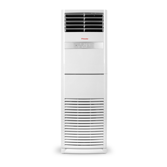
    Gerätespezifikationen und Merkmale Geräteteile Luftauslass Anzeigefeld Betriebstemperatur Wenn Ihr Klimagerät außerhalb der folgenden Temperaturbereiche verwendet wird, können bestimmte Sicherheitsschutzfunktionen aktiviert werden und dazu führen, dass das Gerät abgeschaltet wird. Tip divizare invertor KÜHLUNG HEIZUNG ENTFEUCHTUNG FÜR AUSSENGERÄTE MIT Raum- 17 ° C - 32 ° C 0 °...
  • Seite 126: Typ Mit Fester Drehzahl

    Typ mit fester Drehzahl KÜHLUNG HEIZUNG ENTFEUCHTUNG Raum- 0 ° C-30 ° C 17 ° C-32 ° C (62 ° F-90 ° F) 10 ° C-32 ° C (50 ° F-90 ° F) temperatur (32 ° F-86 ° F) 18 ° C-43 ° C (64 ° F-109 ° F) 11 °...
  • Seite 127: Manueller Betrieb

    Manueller Betrieb HINWEIS: Verschiedene Modelle haben unterschiedliche Anzeigefelder. Nicht alle der unten beschriebenen Anzeigen sind für das von Ihnen erworbene Klimagerät verfügbar. Bitte prüfen Sie das Innenanzeigefeld des von Ihnen erworbenen Geräts. Die Abbildungen in dieser Anleitung dienen nur zur Erläuterung. Die tatsächliche Form Ihres Innengeräts kann leicht abweichen.
  • Seite 128 Anzeige des Automatikbetriebs Kühlbetrieb-Anzeige Anzeige Trockenbetrieb Anzeige Heizbetrieb Anzeige Lüfterbetrieb Anzeige Sperrbetrieb Anzeige des Schwenkbetriebs Anzeige Sleep-Betrieb Anzeige des Turbo-Betriebs Ein-Timer-Betriebsanzeige Anzeige für Aus-Timer-Betrieb Anzeige der Lüftergeschwindigkeit HINWEIS: Wenn das Gerät im COOL-, AUTO- oder DRY-Modus mit einer Solltemperatur von weniger als 24 °C ausgeschaltet wird, wird die Solltemperatur beim erneuten Einschalten des Geräts automatisch auf 24 °C eingestellt.
  • Seite 129: Anzeige Der Lüftergeschwindigkeit

    ➂ Taste für die Lüftergeschwindigkeit: Mit dieser Taste wählen Sie die gewünschte Lüfterstufe. Bei jedem Tastendruck wird die Lüfterstufe in der folgenden Reihenfolge umgeschaltet: HIGH AUTO (einige Geräte) HINWEIS: Im Modus AUTO und DRY können Sie keine Lüftergeschwindigkeit auswählen. Die Lüftergeschwindigkeit wird automatisch gesteuert.
  • Seite 130 ➃ ADJUST-Taste: 1. Temperatur einstellen: Drücken Sie die Tasten « « und « «, um die Temperatur in einem Bereich von 16°C/17 °C~30 °C oder 20°C~28°C einzustellen. 2. Timer-Einstellung: Stellen Sie die Timer-Ein-/Ausschaltzeit im Timer-Einstellmodus ein (0~24hs). 3. Auswahl der Hilfsfunktion: SWählen Sie die gewünschte Hilfsfunktion durch Drücken der Tasten »...
  • Seite 131: Steuerung Der Luftstromrichtung Horizontale Luftstromrichtung (Auto)

    ➆ Taste LOCK: Halten Sie die Tasten und gedrückt, um die Sperrfunktion zu aktivieren. Alle Tasten reagieren nicht, außer Sie drücken diese beiden Tasten erneut, um die Sperrfunktion zu deaktivieren. Wenn Sie im Sperrmodus eine andere Taste auf dem Anzeigefeld drücken, blinkt das Sperrsymbol 5 Sekunden lang mit 1 Hz.
  • Seite 132: Reinigung Und Wartung

    Reinigung und Wartung Reinigung der Inneneinheit VOR DER REINIGUNG ODER VORSICHT WARTUNG • Schalten Sie das Gerät aus und trennen Sie VOR DER REINIGUNG UND WARTUNG es von der Stromversorgung, bevor Sie die STETS DIE KLIMAANLAGE ABSCHALTEN Filter wechseln oder reinigen. UND VOM NETZ TRENNEN.
  • Seite 133: Wartung Große Stillstandszeiten

    Kältemittel-Lecksuchsystem (einige Wartung Vor Beginn Modelle) der Nutzungsperiode • Im Falle eines Kältemittellecks wird auf der LCD-Anzeige “EC” angezeigt. Nach längerer Nichtbenutzung oder fortgesetzter Verwendung des Geräts folgendes durchführen: Wartung Große Stillstandszeiten Wenn Sie vorhaben, die Klimaanlage längere Zeit nicht zu verwenden, beachten Sie folgendes: Stellen Sie sicher, dass nichts alle Lufteinlässe und -auslässe blockiert...
  • Seite 134: Fehler

    Fehler SICHERHEITSHINWEISE Wenn eine der folgenden Bedingungen eintritt, schalten Sie Ihre Klimaanlage sofort aus! • Das Netzkabel ist beschädigt oder ungewöhnlich heiß • Sie riechen einen seltsamen Geruch • Das Gerät macht Lärm oder ungewöhnliche Geräusche • Die Sicherung brennt ist oft durch oder der Sicherungsschalter öffnet sich häufig •...
  • Seite 135 Problem Mögliche Ursache das Außengerät macht Das Gerät kann je nach aktuellem Betriebsmodus verschiedene Geräusche erzeugen. Lärm Wenn das Gerät längere Zeit nicht benutzt wird, kann sich Staub ansammeln, der beim Staub wird aus dem Innen Starten ausgestoßen werden kann. Dies kann durch Abdecken des Geräts während oder Außengerät geblasen Nichtbetriebszeiten eingeschränkt werden.
  • Seite 136 Problem Mögliche Ursache Lösung Asteptati ca energia electrica sa fie Stromausfall restabilita Von der Stromversorgung trennen Reveniti la alimentare Durchgebrannte Sicherung Inlocuiti siguranta Das Gerät arbeitet nicht Die Batterien sind verbraucht Inlocuiti bateriile Asteptati trei minute dupa repornirea Der 3-Minuten-Schutz des Geräts ist aktiviert unitatii Der Timer wurde aktiviert Dezactivati temporizatorul...
  • Seite 137: Bauteile

    Bauteile De Klimaanlage wird mit folgenden Zubehörteilen geliefert. Benutzen Sie alle Bau- und Zubehörteile des Geräts, um die Klimaanlage zu installieren. Durch eine nicht ordnungsgemäße Installation kann ein Wasserleck, Stromschlag, Brand oder Schaden an der Ausstattung verursacht werden. Menge Menge Name Gestalten Name...
  • Seite 138: Installationsübersicht - Innengerät

    Installationsübersicht - Innengerät INSTALLATIONSVORGANG BEFEHL Installieren Sie das Innengerät Installieren Sie das Schließen Sie die Außengerät Kältemittelleitungen an Schließen Sie die Leitungen Evakuieren Sie das Kältesystem Führen Sie einen Probelauf durch ƒSeite 138 „...
  • Seite 139: Einheitsteile

    Einheitsteile Innengerät Außeneinheit Luftauslass Abflussrohr, Entlüftungsrohr Bedienfeld Anschlussleitung Horizontale Luftstromregeljalousie Anschlussleitung Vertikale Luftstromregeljalousie Anschluss Kältemittelleitung Admisie aer Luftaustritt HINWEIS ZU ABBILDUNGEN Die Abbildungen in dieser Anleitung dienen der Veranschaulichung. Die tatsächliche Form Ihres Innengeräts kann geringfügig davon abweichen. Die tatsächliche Form ist ausschlaggebend. ƒSeite 139 „...
  • Seite 140: Installation Der Inneneinheit

    Installation der Inneneinheit Installationsanleitung - Innengerät HINWEIS ZUM WANDLOCH: Wenn keine feste Kühlmittelleitung vorhanden ist: Beim Aussuchen nach einem Installationsort, WICHTIG BEI DER INSTALLATION beachten Sie, dass Sie genügend Platz für das Vergewissern Sie sich vor der Installation des Loch an der Wand lassen müssen (siehe Schritt Innengeräts, dass die auf der Produktverpackung “Öffnen Sie das Loch an der Wand für die angegebene Modellnummer des Innengeräts...
  • Seite 141: Passen Sie Die Wandplatte An Der Wand

    Schritt 2: Passen Sie die Wandplatte an der ACHTUNG Wand Wenn eine zusätzliche Abstützung erforderlich 1. Entfernen Sie die Schraube, wo die Wandplatt ist, um ein Herunterfallen des Geräts zu auf der Rückseite des Innengeräts angepasst verhindern, kann ein Schutzkeil installiert wird.
  • Seite 142: Dichtungskitt Auftragen Und Wandlochabdeckung Installieren

    3. Ordnen Sie die Rohre so an, dass der HINWEIS Ablaufschlauch unten, die Anschlussrohre in der Mitte und die elektrische Verdrahtung oben • Nur Modelle mit Lüftungsfunktion enthalten liegen. Lüftungskanäle. 4. Verwenden Sie Vinylband, um mit dem • Die Anzahl und Art der verwendeten Abkleben der Rohre zu beginnen.
  • Seite 143: Schließen Sie Den Ablaufschlauch An

    Installation des Ablaufschlauchs innen Wand Außenbereich Innenbereich Andernfalls Abflussrohr Leckage Abdeckband für ≈ 0,5 ~ 1cm Rohre / 0,2 ~ 0,4 inch 1. Stellen Sie sicher, dass die Ablaufleitung mit der Außenseite nach unten verbunden. 3. Setzen Sie die Wandschutzhülse in die Bohrung. 2.
  • Seite 144: Installation Der Außeneinheit

    Installation der Außeneinheit Installieren Sie das Gerät gemäß Installieren Sie das Gerät NICHT an den folgenden Orten: den örtlichen Vorschriften und Bestimmungen, es kann leichte x In der Nähe von Hindernissen, die den Eintritt Unterschiede zwischen verschiedenen und Austritt der Luft behindern Regionen geben.
  • Seite 145: Schritt 2: Installieren Sie Die Ablaufkupplung (Nur Wärmepumpe)

    Schritt 2: Installieren Sie die Ablaufkupplung IN KALTEN KLIMAZONEN (nur Wärmepumpe) Achten Sie in kalten Klimazonen darauf, dass Bevor Sie das Außengerät festschrauben, müssen der Ablaufschlauch möglichst senkrecht Sie die Ablaufgarnitur an der Unterseite des verläuft, um einen schnellen Wasserabfluss Geräts installieren.
  • Seite 146 Installationsreihen in Reihe Die Beziehungen zwischen H, A und L sind wie folgt 25 cm / 9,8 ”keine Installation L ≤ 1/2H L ≤ H 30 cm / 11,8 ”keine Installation 1/2H < L ≤ H Kann nicht installiert werden L >...
  • Seite 147: Anschlußhinweise - Kältemittelleitung

    Anschließen von Kältemittelleitungen Achten Sie beim Anschluss der Kältemittelleitungen darauf, dass keine anderen Stoffe oder Gase als das angegebene Kältemittel in das Gerät gelangen. Das Vorhandensein anderer Gase oder Substanzen verringert die Leistung des Geräts und kann einen abnormal hohen Druck im Kühlkreislauf verursachen. Dies kann zu Explosionen und Verletzungen führen.
  • Seite 148: Entfernen Der Grate

    die Funktion und die Energieeffizienz des Geräts. Die Abb. 6.3 Fig. 5.3 Sie müssen vollständig entfernt werden. Länge von 5 Metern (16.5ft) getestet. Die Mindestlänge 1. Halten Sie die Leitung in einer vertikalen 4. Entfernen Sie das Kunststoffisolierband ermeidung von Vibrationen und intensiven Geräuschen zu Neigung, um zu vermeiden, dass die Grate in von den Leitungsenden, wenn Sie mit dem e maximale Länge der Kältemittelleitung 10 Meter (32.8ft)
  • Seite 149: Anschließen Der Rohre

    Schritt 4: Anschließen der Rohre HINWEISE AUF DEN MINDESTRADIUS VON BIEGEN Schließen Sie zuerst die Kupferrohre an das Innengerät und dann an das Außengerät an. Sie Biegen Sie die Schläuche vorsichtig in der Mitte sollten zuerst die Niederdruckleitung und dann gemäß...
  • Seite 150: Installation Des Außengeräts

    Installation des Außengeräts BEVOR SIE IRGENDETWAS DAVON Jeder Anschluss muss fest verbunden sein. MERKEN ELEKTRISCHE ARBEITEN, Lose Drähte können zu einer Überhitzung LESEN DIESE REGELN des Terminals führen, was zu einem Produktausfall und einem Brand führen 1. Alle Kabel müssen den folgenden kann.
  • Seite 151: Minimale Querschnittsfläche Von Strom- Und Signalkabeln (Als Referenz)

    HINWEIS ZUM LUFTSCHALTER Comutator de aer Wenn der maximale Strom des Klimageräts (achizitionate separat) Comutator de aer mehr als 16 A beträgt, muss ein Luftschalter (achizitionat Firele de alimentare ale oder ein Leckageschutzschalter mit separat) unitatii interioare Schutzvorrichtung (separat erhältlich) Firele de alimentare ale verwendet werden.
  • Seite 152: Verdrahtung

    b. Entfernen Sie mit einer Abisolierzange die 3.Schließen Sie die U-Stecker an die Klemme an. Gummiummantelung an beiden Enden Stimmen Sie die Farben/Beschriftungen des Signalkabels, so dass ca. 15 cm Kabel der Drähte mit den Beschriftungen auf freiliegen. der Klemmenleiste ab und schrauben Sie c.
  • Seite 153: Entlüftung

    Entlüftung 6. Schließen Sie die Seite der niedrigen Heizung Vorarbeit und Anweisungen des Ventilblocks und schalten Sie die Luft und andere Fremdkörper im Kühlkreislauf Vakuumpumpe aus. können zu einem ungewöhnlichen Druckanstieg 7. Warten Sie 5 Minuten und prüfen Sie dann, ob führen, der die Klimaanlage beschädigen, die Leistung beeinträchtigen und Verletzungen sich der Systemdruck nicht ändert.
  • Seite 154: Hinweis Zur Kältemittelzugabe

    Uhrzeigersinn drehen. Hören Sie wie die Abgase aus dem System abgelassen werden und schließen Sie das Ventil nach 5 Sekunden. ÖFFNEN SIE VORSICHTIG DIE 10. Beobachten Sie das Druck-Manometer eine VENTILE Minute lang, um sicherzustellen, dass sich der Druck nicht ändert. Das Manometer sollte Wenn Sie die Ventile öffnen, drehen Sie Hinweis zur Kältemittelzugabe einen Wert leicht über dem Atmosphärendruck...
  • Seite 155: Testbetrieb

    TESTBETRIEB c. Prüfen Sie doppelt, um zu sehen, ob die Vor dem Test Raumtemperatur wird erfasst richtig. Nach der Installation muss ein Test d. Vergewissern Sie sich, dass die Anzeigen leuchten. Die Fernbedienung und das durchgeführt werden Installation des Anzeigefeld am Innengerät ordnungsgemäß gesamten Systems.
  • Seite 156 Die Abbildungen in diesem Handbuch dienen lediglich zur Erläuterung der Funktionen. Die tatsächliche Form der Einheit, die Sie gekauft haben, kann etwas abweichen, aber die Bedienung und Funktionen sind gleich. Das Unternehmen übernimmt keinerlei Haftung für eventuell in diesem Dokument enthaltene falsch gedruckte Informationen.
  • Seite 157 Kaufdatum* Postleitzahl* Adresse* Seriennummer des Gerät Seriennummer des Geräts* Klicken Sie an SENDEN an der linken Seite des Garantie Antrags: Abonnieren Sie den Newsletter von Inventor Weitere Informationen Belegnummer* E-mail* Rufnummer* * Pflichtfeld Mit der Garantiekarte akzeptieren Sie unsere Geschäftsbedingungen.
  • Seite 158 NOTES...
  • Seite 160 “Owner’s Manual - Product Fiche” in the packaging of the outdoor unit. (European Union products only). INVENTOR A.G. S.A. Manufacturer: 24th km National Road Athens - Lamia & 2 Thoukididou Str., Ag.Stefanos, 14565 Tel.: +30 211 300 3300, Fax: +30 211 300 3333 - www.inventor.ac...

Diese Anleitung auch für:

V5mfo-66

Inhaltsverzeichnis