
Verwandte Anleitungen für Endress+Hauser asp-station 2000


Inhaltszusammenfassung für Endress+Hauser asp-station 2000
- Seite 1 Stationary water sampler BA 080R/09/c4/10.03 No.: 50092406 asp-station 2000 Betriebsanleitung Operating instructions Manuel de mise en service Istruzioni d´impiego...
- Seite 2 ASP-Station 2000 Endress+Hauser...
- Seite 3 English 57 ... 110 (Please read before installing the unit) 19...34 Unit number:......... Préleveur d’échantillons en poste fixe ASP-Station 2000 Français Manuel de mise en service English 111 ... 165 (Veuillez lire attentivement le présent manuel avant de mettre en service l’appareil) 19...34...
- Seite 4 Kurzanleitung ASP-Station 2000 Kurzanleitung Mit der folgenden Kurzanleitung können Sie Ihr Gerät in der richtigen Reihenfolge voll- ständig, schnell und einfach installieren und in Betrieb nehmen: → Kap. 1 Sicherheitshinweise → Kap. 3 1. Schritt: Gerät aufstellen → Kap. 3.3.4 2.
-
Seite 5: Inhaltsverzeichnis
ASP-Station 2000 Inhaltsverzeichnis Inhaltsverzeichnis Sicherheitshinweise Kalibrierung ......20 .... -
Seite 6: Sicherheitshinweise
Die ASP-Station 2000 ist in der Standardausführung (RPS20-) nicht für die Aufstellung in explosionsgefährdeten Bereichen geeignet. Optional ist die ASP-Station 2000 (RPS22-) mit einer Zertifizierung für die Aufstellung in explosionsgefährdeten Bereichen der ATEX Zone 2 (ATEX II3G EEx nA/C IIC T4) erhält- lich. -
Seite 7: Rücksendung
Reparatur, zurücksenden: • Legen Sie dem Gerät in jedem Fall ein vollständig ausgefülltes “Gefahrgutblatt” bei. Nur dann ist es Endress+Hauser möglich, ein zurückgesandtes Gerät zu transportie- ren, zu prüfen oder zu reparieren. • Legen Sie der Rücksendung spezielle Handhabungsvorschriften bei, falls dies not- wendig ist, z.B. -
Seite 8: Identifizierung
Software: LDU003A Abb. 1:Typenschildangaben für die "ASP-Station 2000" Lieferumfang Lieferumfang Der Lieferumfang des Probenehmers besteht aus: • ASP-Station 2000 • Betriebsanleitung • RS232 Schnittstellenkabel (optional) • Gerätesoftware ReadWin 2000 (optional) Hinweis! Beachten Sie im Kap. 8 die Zubehörteile des Probenehmers. -
Seite 9: Montage
RS232 (Option) h: Steuerung i: Schrankdach j: Dorsiereinheit k: Drehhahn Abb. 2: ASP-Station 2000 Montageübersicht Warenannahme, Transport, Lagerung 3.2.1 Warenannahme Kontrollieren Sie nach der Warenannahme folgende Punkte: • Sind Verpackung oder Inhalt beschädigt? • Ist die gelieferte Ware vollständig? Vergleichen Sie den Lieferumfang mit Ihren Bestel- langaben. -
Seite 10: Einbaubedingungen
3 Montage ASP-Station 2000 Einbaubedingungen 3.3.1 Einbaumaße Einbaubedingungen Die Abmessungen des Probenehmers finden Sie im Kap. »Konstruktiver Aufbau« auf Seite 53. 3.3.2 Einbauort Abb. 3: Hinweise zur Aufstellung des Gerätes Bitte beachten Sie bei der Aufstellung des Gerätes folgende Punkte: ❑... -
Seite 11: Fundamentplan
ASP-Station 2000 3 Montage 3.3.3 Fundamentplan Abb. 4: Fundamentplan (alle Angaben in mm) A: Befestigung (4 x M10) B: Kabelschacht C: Ablauf für Kondenswasser D: Schlaucheinführung unten (Option) E: Ablauf für Überlauf 3.3.4 Hydraulischer Anschluss • Maximale Ansaughöhe: Standard 6 m; Option: 8 m •... -
Seite 12: Probenahme Mit Durchflussarmatur
3 Montage ASP-Station 2000 3.3.5 Probenahme mit Durchflussarmatur Die Probe wird direkt, aus der im Schrankunterbau eingebauten Durchflussarmatur, ent- nommen. Anwendung findet die Durchflussarmatur bei der Probenahme von druckbeaufschlag- ten Systemen, z.B.: • höhergelegenen Behältern • Druckrohrleitungen • Förderung mit externen Pumpen Anschlüsse... -
Seite 13: Einbau
ASP-Station 2000 4 Verdrahtung Einbau Wasseranschlüsse Stellen Sie das Gerät unter Berücksichtigung der Einbaubedingungen → Kap. 3.3 auf. Verlegen Sie den Entnahmeschlauch von der Entnahmestelle zum Gerät. Hinweis! Beachten Sie bitte hierbei die Anforderungen an die Probenentnahmestelle unter 3.3 "Einbaubedingungen". -
Seite 14: Dachmontage
4 Verdrahtung ASP-Station 2000 Hinweis! Der Klemmenanschluss befindet sich geschützt unter dem Schrankdach im Elektroni- kraum des Gerätes. Vor Inbetriebnahme muss daher zum Anschluss der Hilfsenergie die Rückwand und das Dach des Gerätes entfernt werden. Zur Montage der Rückwand und des Dachs gehen Sie in umgekehrter Reihenfolge wie in den folgenden beiden Kapiteln beschrieben vor. -
Seite 15: Klemmenbelegung Der Klemmenplatine
ASP-Station 2000 4 Verdrahtung Klemmenbelegung der Klemmenplatine Schnittstelle RS485 Leitungs- widerstand RS 485 RxD/TxD(A) RxD/TxD(B) weitere Geräte RxD/TxD(A) Drucker RxD/TxD(B) 9pol. ser.Schnittstelle Analogeingang Strom Spannung RxD/TxD(A) 0...20 mA, GND via 100 (int.) 0...1 V 4...20 mA R>1M int. Shunt: 50... -
Seite 16: Anschluss Rs232 Schnittstelle (Standard)
An die Anschlussbuchse (3,5 mm, Klinkensteckerbuchse) für die digitale Schnittstelle RS232 wird über das RS232 Schnittstellenkabel (3,5 mm, Klinkenstecker) ein PC (9-poli- ger SUB-D Stecker) angeschlossen. Eine Fernparametrierung und Messdatenabfrage über den PC ist mit der Endress+Hauser Gerätesoftware ReadWin 2000 möglich. n.c. n.c. -
Seite 17: Anschluss Rs485 Schnittstelle
An die Anschlussbuchse (4-polig, weiblich) für die digitale Schnittstelle RS232 wird über das RS232 Schnittstellenkabel (4-polig, männlich) ein PC (9-poliger SUB-D Ste- cker) angeschlossen. Eine Fernparametrierung und Messdatenabfrage über den PC ist mit der Endress+Hauser Gerätesoftware ReadWin 2000 möglich. 4.1.8 Anschluss RS485 Schnittstelle (Option) Die RS485 Schnittstelle befindet sich auf der Klemmenplatine. -
Seite 18: Bedienung
5 Bedienung ASP-Station 2000 Bedienung Bedienung auf einen Blick Hinweis! Vor dem Einschalten bitte Kap. 6.1 "Installations- und Funktionskontrolle" sowie 6.2 "Messgerät einschalten" beachten! Bedienung auf einen Blick Scrolltasten Meldeliste Start Probenah- "Quick-Setup"; meprogramm Setup; Geräteeinstel- lungen; Service; Start manuelle Probenstatistik Gerät ein- und... -
Seite 19: Anzeigendarstellung
ASP-Station 2000 5 Bedienung 5.2.1 Anzeigendarstellung Die Einstellung des Probenehmers erfolgt über vier Bedientasten. Die Funktion der Tas- ten wird auf dem Display angezeigt. Die Bedienung ist menügeführt. Abb. 17:: Anzeigendarstellung Auswahllisten zeigen automatisch die mögli- chen Einstellungen an. Die angewählte Ein- stellung (hier: Zeit, Menge, ext. -
Seite 20: Bestätigung Von Fehlermeldungen
5 Bedienung ASP-Station 2000 Der Benutzercode wird in der Menüebene SET - GERÄTEEINSTELLUNGEN unter der Funktion CODE eingegeben. Bestätigung von Fehlermeldungen Bestätigung von Fehler- Fehlermeldungen auf dem Display der Steuerung werden durch Drücken der Bedien- meldungen taste unter dem OK-Feld quittiert. -
Seite 21: Manuelle Einstellung Des Probenvolumen Beim Standardgerät
ASP-Station 2000 5 Bedienung 5.6.2 Manuelle Einstellung des Probenvolumen beim Standard- gerät Die Einstellung des gewünschten Probevolumens erfolgt durch manuelles Verschieben des Dosierrohres. Gehen Sie zur Kalibrierung des Probenvolumens folgendermaßen vor: 1. Eingestelltes Probenvolumen des aktiven Programms überprüfen. 2. Dosierglas ausbauen, dazu Klemmhebel und Luft- schlauch lösen. -
Seite 22: Kalibrierung Dosiervolumen Für Durchflussproportionale Probenahme "Twiddle-Prinzip" (Option)
5 Bedienung ASP-Station 2000 5.6.3 Kalibrierung Dosiervolumen für durchflussproportionale Probenahme "Twiddle-Prinzip" (Option) Die Kalibrierung des Probenvolumens bei der durchflussproportionalen Probenahme muss immer durchgeführt werden, wenn: – das Gerät das erste mal oder an einem neuen Aufstellungsort in Betrieb genommen wird –... -
Seite 23: Inbetriebnahme
ASP-Station 2000 6 Inbetriebnahme Inbetriebnahme Installations- und Funktionskontrolle Installations- und Wenn Sie folgende Fragen mit JA beantworten können, können Sie das Gerät in Betrieb Funktionskontrolle nehmen (siehe Kap. 6.2 "Messgerät einschalten"). Bei NEIN bitte im entsprechenden Kapitel nachlesen: Allgemein Hinweis Kapitel →... -
Seite 24: Quick-Setup
6 Inbetriebnahme ASP-Station 2000 Quick-Setup Abb. 23: Quick-Setup ASP-Station 2000 Endress+Hauser... -
Seite 25: Gerätekonfiguration
ASP-Station 2000 6 Inbetriebnahme Gerätekonfiguration Hinweis! Für die jeweiligen Konfigurationsparameter sind die Menüstrukturen mit Display- Anzeige und Auswahlliste in den Abbildungen angegeben. Unter den jeweiligen Abbil- dungen befinden sich Tabellen, welche die zugehörigen Funktionsbeschreibungen zu den Parametern beinhalten. 6.4.1 Parametrierung der Eingänge Parametrierung der Ein- Bei einer Parametrierung im "Quick-Setup"... -
Seite 26: Analogeingang
Zur richtigen Verdrahtung des Analogeingangs s. Kap. 4.1.5 6.4.2 Parametrierung des internen Daten-Logger (Option) Die ASP-Station 2000 verfügt optional über einen internen Daten-Logger. Dieser spei- chert die Daten eines angeschlossenen Analogsignals und die Probenahmeereignisse (Probenvolumen, Flaschenfüllzeiten, Ereignisse...). Der Analogwert kann ein Mengen- signal sein aber auch pH-Wert, Leitfähigkeit, Trübung usw... -
Seite 27: Parametrierung Der Ausgänge
ASP-Station 2000 6 Inbetriebnahme Der interne Daten-Logger wird wie folgt aktiviert und parametriert: 1. Wählen Sie unter: <SET -> Geräteeinstellungen -> den Menüpunkt "Speicher Intervall" aus. 2. Stellen Sie bitte die Abtastrate für das Analogsignal ein. Die Kapazität des Ringspeichers wird dann auto- matisch im Display angezeigt. -
Seite 28: Programmauswahl
6 Inbetriebnahme ASP-Station 2000 Netzaus Der Ausgangskontakt wird bei einem Netzausfall geschaltet Probe Der Ausgangskontakt wird bei einer Probenahme geschaltet Flasche Der Ausgangskontakt wird bei einem Flaschenwechsel geschaltet Ext.Stopp Der Ausgangskontakt wird bei einem externen Stopp geschaltet Füllende Der Ausgangskontakt wird nach Beenden des Probenahmeprogramms geschaltet Kein Zufl. - Seite 29 ASP-Station 2000 6 Inbetriebnahme Für die 7-Programmversion stehen mehrere Programmkombinationen zur Verfügung: Ein Hauptprogramm ist aktiv Ein Hauptprogramm und ein Umschaltprogramm sind aktiv 1+Ereignis Ein Hauptprogramm und das Ereignisprogramm sind aktiv 2+Ereignis Ein Hauptprogramm, ein Umschaltprogramm und das Ereignisprogramm sind aktiv Hauptprogramme Es stehen 4 Hauptprogramme zur Verfügung.
-
Seite 30: Hauptprogramm Erstellen
6 Inbetriebnahme ASP-Station 2000 6.4.5 Hauptprogramm erstellen Hauptprogramm erstel- Menüstruktur: Abb. 29: Menüstruktur Hauptprogramm Probenahmearten Menüstruktur: Programm 1 Name Programm 1 Probe > Probe Verteilung > Zeit Start-Stopp > -modus : Zeit Menge Synchronisation > Zeit 00:15 ext.Sign. Rückstellprobe >... -
Seite 31: Verteilung
Die Probenahme wird in einstellbaren Zeitintervallen ausgelöst. Die entnom- mene Probemenge ist dabei proportional zu einer gemessenen Durchfluss- menge. Hinweis! Für diese Funktion muss die ASP-Station 2000 mit einer dfp-Dosiereinheit ("Twiddle-Prinzip") ausgerüstet sein. Zusätzlich muss ein Mengensignal an dem Analogeingang des Probenehmers angeschlossen sein. Shots: Anzahl der Probenahmen je Probenahmezyklus. -
Seite 32: Umschaltprogramme Erstellen
6 Inbetriebnahme ASP-Station 2000 Der Start des Probenahmeprogramms kann entweder sofort mit Drücken der AUT-Taste oder zu einem einstellbaren Zeitpunkt erfolgen. Der Stopp des Probenahmeprogramms kann wie folgt festgelegt werden: • Programmende: das Gerät stoppt selbsttätig die Probenahme nach Durchlaufen des eingestellten Programms •... -
Seite 33: Ereignisprogramm Erstellen
ASP-Station 2000 6 Inbetriebnahme In den Umschaltprogrammen kann wie in den Hauptprogrammen die Probenentnahme Zeit-, Mengen-, Durchflussproportional oder durch externes Signal ausgelöst werden. Verteilung Für die Umschaltprogramme können separate Flaschen reserviert werden. Grundsätz- lich gilt, mit Ausnahme bei einer parallelen Rückstellprobenahme, bei der Einteilung der Flaschenverteilung: Die erste Flaschengruppe einer Verteilung ist für die Hauptprogramme reserviert. - Seite 34 6 Inbetriebnahme ASP-Station 2000 Probenahmemodus Menüstruktur: Ereignispr Probe Probe > Zeit Verteilung > -modus Zeit Menge Rückstellprobe > Zeit 00:15 ext.Sign Volumen 100ml Durchfluss Shots <-' â <-' â á Abb. 37: Menüstruktur Probenahmemodus Im Ereignisprogramm stehen für die Probeentnahme die gleichen Möglichkeiten (Zeit-, Menge-, ext.Signal- und Durchfluss) zur Verfügung wie in den Haupt- und Umschaltpro-...
-
Seite 35: Aktiviert
ASP-Station 2000 6 Inbetriebnahme 6.4.8 Rückstellprobenahmeprogramm erstellen Definition Parallele/gleichzeitige Probenahme von zwei Proben in separate Behälter. Rückstellprobenahme aktivieren Menüstruktur: Umschalt 2 Rückstellprobe Probe > Verteilung > Rückstellprobe > Aktiviert : ext.Sign nein â á <-' â á <-' Abb. 39: Menüstruktur Aktivierung Rückstellprobenahme... -
Seite 36: Programmstopp-Optionen "Reset" Der Rückstellprobenahme
6 Inbetriebnahme ASP-Station 2000 Die Position der Flaschen für die Rückstellprobe kann am Anfang (ab Behälter 1), in der Mitte (vor den Flaschen des Umschalt- und Ereignisprogrammes) oder am Ende der Flaschenverteilung definiert werden. Programmstopp-Optionen "Reset" der Rückstellprobenahme Menüstruktur: Abb. 42: Menüstruktur Reset Rückstellprobenahme Der Programmstopp "Reset"... - Seite 37 ASP-Station 2000 6 Inbetriebnahme ↵ Datum-Uhrzeit Datum: Aktuelles Datum eingeben MEZ mit auto. ↵ Geräteeinstellungen Uhrzeit: Ortszeit eingeben Sommer-Winter- Datum-Uhrzeit Umschalt: Modus der Sommer-/Winterzeitumschaltung aus- zeit -Umschal- wählen tung Sommerzeit: Datum und Wert der Sommerzeitumschaltung Normalzeit: Datum und Wert der Winterzeitumschaltung ↵...
- Seite 38 6 Inbetriebnahme ASP-Station 2000 Programme ändern - Hauptprogramme ↵ Probemodus Zeit: Zeit ↵ Programme ändern Probenahme zeitproportional; ↵ Programm 1,2,3,4 Menge: ↵ Probe Probenahme mengenproportional (Mengensignal anschlie- Modus ßen!); ext.Sign.: Probenahme bei externen Signal (Signaleingang belegen!); Durchfluss (Optional): Probenahme proportional zum Durchfluss (Mengensignal anschließen)
- Seite 39 ASP-Station 2000 6 Inbetriebnahme Programme ändern – Umschaltprogramme ↵ Umschalt Probe: Probenahmeart im Umschaltprogramm ↵ Programme ändern Verteilung: Verteilungsmodus für das Umschaltprogramm Umschalt 1,2 ↵ Probe Zeit: Probenahme zeitproportional Zeit ↵ Programme ändern Menge: Probenahme mengenproportional (Mengensignal ↵ Umschalt 1,2 anschließen!)
-
Seite 40: Konfiguration Mit Profibus
7 Wartung ASP-Station 2000 Konfiguration mit Profibus Eine detaillierte Beschreibung der Parametrierung und Konfiguration der ASP-Station 2000 mit Profibus-DP entnehmen Sie bitte der "Zusatzbeschreibung zur Betriebsanlei- tung: Anbindung ASP2000 an Profibus DP über die serielle Schnittstelle mit is ProGate" (siehe 10.10 "Ergänzende Dokumentationen"). -
Seite 41: Reinigung Des Probenraums
Staubbildung), in regelmäßigen Abständen mit Pressluft ausgeblasen werden. Wartungsempfehlung Hinweis! Endress+Hauser bietet Ihnen für Ihre ASP-Station 2000 einen Wartungsvertrag an. Durch einen Wartungsvertrag erhöhen Sie die Betriebssicherheit und entlasten Ihr Betriebspersonal. Ausführliche Angaben zu Wartungsverträgen erhalten Sie von Ihrer E+H-Serviceorganisation. -
Seite 42: Zubehör
8 Zubehör ASP-Station 2000 Folgende Teile der ASP-Station 2000 sollten in den angegebenen Abständen geprüft und ggf. ersetzt werden: 1. Membranpumpe; Dichtungssatz; mind. Intervall: 2 Jahre 2. Airmanager; komplett; mind. Intervall: 2 Jahre 3. Luftfilter; mind. Intervall: 1 Jahr 4. O-Ring Dichtungen; mind. Intervall: 1 Jahr 5. -
Seite 43: Störungsbehebung
ASP-Station 2000 9 Störungsbehebung Bestell-Code Zubehörteil RPS20A-B3 Sammelbehälter PE 30 l RPS20A-B6 Sammelbehälter PE 60 l RPS20A-VA Rundverteilereinheit inkl. Drehhahn, Drehhahnantrieb, Rahmen für Verteilerwannen 50089636 Verteilerwanne 6er für Verteilungen mit 12 Flaschen 50089637 Verteilerwanne 12er für Verteilungen mit 24 Flaschen ®... -
Seite 44: Prozessfehler Ohne Meldungen
9 Störungsbehebung ASP-Station 2000 Temperatur im Probenraum > Einbaubedingungen überprüfen FEHLER: Übertemp.Ober- 70°C, Temperaturfühler defekt s. Kap. 3.3, Reparatur durch raum. E+H Service Fehlerhafte Kommunikation zwi- Verbindungen prüfen, Betriebs- FEHLER: Profibus schen ASP2000 und Profibus- zustand der SPS prüfen koppler FEHLER: Drehhahn manipul. -
Seite 45: Ersatzteile
ASP-Station 2000 9 Störungsbehebung Ersatzteile Ersatzteile Abb. 46: Ersatzteile ASP Station 2000 (Positionsnummern sind in der Ersatzteilliste erläutert) Pos. A: Elektronikraum nach Dachdemontage, siehe Kap. 4.1.3 (Ansicht von oben) Pos. B: Dosiereinheit Steuerung/CPU Ausführung Station Software / CPU / Steuerung... - Seite 46 9 Störungsbehebung ASP-Station 2000 Pos.-Nr. Bestell-Code Gehäuse und Gehäuseteile RPS20X-LS Leerschrank mit Kühlaggregat RPS20X-LB Dach kpl. 51000287 Rückwand (Schrank) 51000288 Türe kpl. Standard RPS20X-LC Dichtungssatz für Türe (Standardschrank) RPS20X-LD Dichtungssatz für zweiteilige Türe 51000233 Schlüssel (1 Paar) 51000244 Schloss mit Schlüssel...
- Seite 47 ASP-Station 2000 9 Störungsbehebung 50090342 Deckel für Dosierbecher mit Dosierrohr 200 ml 50072149 Dosierbecher aus Acryl 200 ml 50072150 Überwurfring Dosierbecher 200 ml 50042898 Anschlußbogen kpl. RPS20X-DH Dosiereinheit Glas 350 ml RPS20X-DD LF-Sondensatz (200 ml) (nur im Dosierbecher 200 ml)
-
Seite 48: Entsorgung
9 Störungsbehebung ASP-Station 2000 Softwarenachrüstung (Programm, Bediensprache) Software 7 Programme Sprache Deutsch Englisch Französisch Italienisch Spanisch Holländisch/Niederländisch Dänisch Tschechisch Polnisch ⇐ RPS20A1- Order-Code Entsorgung Entsorgung Für eine spätere Entsorgung des Gerätes beachten Sie bitte die Entsorgungsvorschrif- ten Ihres Landes. Endress+Hauser... -
Seite 49: 10 Technische Daten
ASP-Station 2000 10 Technische Daten Technische Daten 10.1 Arbeitsweise und Systemaufbau Messprinzip Die ASP-Station 2000 ist ein stationärer Probenehmer zur vollautomatischen Entnahme, definierten Verteilung und thermostatisierten Lagerung flüssiger Medien. Probenentnahme- einrichtung Abb. 47: Entnahmeprinzip Pos. 1: Dosierbecher Pos. 2: Dosierrohr Pos. - Seite 50 10 Technische Daten ASP-Station 2000 Abb. 48: Dosiersystem Pos. A: Leitfähigkeitssonde (lang) Pos. B: Leitfähigkeitssonde (lang) Pos. C: Leitfähigkeitssonde (kurz) Pos. D: Dosierrohr Im Dosierbecherdeckel befinden sich drei Leitfähigkeitssonden. Die Probenflüssigkeit erreicht beim Ansaugvorgang zunächst die längeren Leitfähigkeitssonden (Pos. A und B).
- Seite 51 Neben einem 30 l- und 60 l-Sammelbehälter stehen verschiedene Flaschen- verteilungen zur Verfügung. Ein Austausch oder Wechsel der Verteilungsvarianten ist einfach und ohne Werkzeug möglich. Die ASP-Station 2000 erlaubt eine flexible Konfig- uration der Probenverteilung. Für die Haupt-, Umschalt-, und Ereignisprogramme kön- nen Einzelflaschen und Flaschengruppen frei definiert werden.
-
Seite 52: Hilfsenergie
10 Technische Daten ASP-Station 2000 und im internen Data-Logger aufgezeichnet. Der Verdampfer und die Abtauheizung sind, geschützt vor Korrosion und Beschädigung, hinter der Innenschale in die PU-Iso- lierung eingeschäumt. Der Kompressor und der Verflüssiger befinden sich im Oberteil des Probenehmers. -
Seite 53: Prozessbedingungen
ASP-Station 2000 10 Technische Daten • Steuerung (Frontplatte): IP 65 Schutzart • Probenraum: IP 54 • Elektronikraum: IP 43 Elektromagnetische Nach EN 61 326 Verträglichkeit (EMV) 10.5 Prozessbedingungen Mediumstemperatur-bere- 0 bis +50 °C Betriebsdruckbereich drucklos (Standard) Probenmedien Werkstoffbeständigkeiten der medienführenden Teile beachten! Verwendung der kapazitiven Mediumserkennung (optional) bei •... -
Seite 54: Anzeige Und Bedienoberfläche
Innendurchmesser Ansaugschlauch: 13 mm, 16 mm oder 19 mm 10.7 Anzeige und Bedienoberfläche Fernbedienung + Data log- Schnittstelle ging (optional) PC-Schnittstelle RS232. Besonders komfortabel ist die ASP-Station 2000 (sowie weitere ® E+H Geräte) mit der PC Software ReadWin 2000 zu parametrieren. ® Vorteile der PC-Software ReadWin 2000: •... -
Seite 55: Zubehör
Zubehörteile siehe unter Kap. 8 "Zubehör" 10.10 Ergänzende Dokumentationen ❑ Produktgruppe Umwelttechnik - Automatische Probenehmer für flüssige Medien (PG 005R/09/de) ❑ Technische Information ASP-Station 2000 (TI 059R/09/de) ❑ Ex-Zusatzdokumentationen: ATEX (XA 017R/09/a3) ❑ Zusatz-Betriebsanleitung ASP2000: DP-Slave-Modul_is Pro Gate (ZBA 146R/09/de) ❑ Zusatz-Betriebsanleitung ASP2000: kapazitive Mediumserkennung (ZBA 119R/09/a2) ❑... - Seite 56 Index ASP-Station 2000 Index Analogeingang ......26 Parametrierung der Eingänge ....25 Anschluss Ladegerät .
- Seite 57 111 ... 165 (Veuillez lire attentivement le présent manuel avant de mettre l’appareil en service) 19...34 de l’appareil :........Stazione di campionamento ASP station 2000 Italiano Istruzioni d’impiego English 166 ... 195 (Leggere prima di installare l’unita’) 19...34 Numero di serie:......Endress+Hauser...
- Seite 58 4th step: Operation & calibration → Section 6 5th step: Commission device → Section 6.5 6th step: Operate device / device functions Set device parameters and sampling programmes → Section 7 7th step: Maintain device - Clean device - Maintenance recommendation Endress+Hauser...
- Seite 59 Calibration ......74 5.6.1 Tap calibration ....74 5.6.2 Manual sample volume setting on stand- Endress+Hauser...
-
Seite 60: Safety Instructions
Repairs Repairs that are not described in these Operating Instructions may only be carried out directly at the manufacturer's or by the ENDRESS+HAUSER service department. Hazardous areas The standard version of the ASP station 2000 (RPS20-) is not suitable for mounting in Ex areas. -
Seite 61: Return
Endress+Hauser, for example for repair: • Always enclose a fully-completed “Dangerous Goods Sheet” with the device. Only then can Endress+Hauser transport, test or repair a returned device. • If necessary, include special handling regulations with the returned product, e.g. a safety datasheet in accordance with EN 91/155/EEC. -
Seite 62: Identification
ASP station 2000 Identification Device designation 2.1.1 Nameplate Device designation Compare the nameplate on the device with the following diagram: ENDRESS+HAUSER a: Device designation 87484 Nesselwang / Germany 2002 b: Order code ASP 2000 c: Device serial number d: Order number... -
Seite 63: Installation
• The device must be packed in shockproof packaging for storage (and transport). The original packaging offers the best protection for this. • The permitted storage temperature is -20...+60 °C (preferably +20 °C). Note! Always transport the cabinet vertically. Do not tilt it! Endress+Hauser... -
Seite 64: Installation Conditions
(the distance between the wall and the rear side of the cabinet should be at least 100 mm). ❑ Do not position the cabinet directly above the channel of the inflow to the wastewater treatment plant (sulphurous vapours!). Endress+Hauser... -
Seite 65: Foundation Plan
• Suction filter: Impedes the entry of coarse solids and solids which can cause clogging. • Immersion assembly: the adjustable immersion assembly fixes the sampling hose at the sampling point. • Hose end piece Order numbers, see “Accessories” on page 96. Endress+Hauser... -
Seite 66: Sampling With A Flow Assembly
When a settable delay time has elapsed, the sampler then takes the sample directly from the flow assembly. Valve V2 is closed again once the sample has been taken. Note! Valves V1 and V2 are not contained in the scope of delivery. Endress+Hauser... -
Seite 67: Installation Instructions
• You should plan a cable length of approx. 1.7 m between the foundation to the terminal connection. 4.1.2 Cable types - Power supply: e.g. NYY-J; 3-core; max. 2.5 mm - Analogue, signal and message lines e.g. LiYY 10 x 0.34 mm - Interface RS485: e.g. LiYCY 2 x 0.25 mm Endress+Hauser... -
Seite 68: Mounting The Cover
4.1.4 Mounting the rear panel 2. Lift the rear panel up and remove it. 1. Loosen the fixing screws. Fig. 8: Mounting the rear panel 4.1.5 Terminal assignment Fig. 9: Position of the terminal board in the electronics compartment Endress+Hauser... - Seite 69 You can set the following signals at the terminal board: Input signals: • 3 digital signals >20 ms • 1 analogue signal 0 to 1 V, 0 to 20 mA, 4 to 20 mA Output signals: • 3 relay outputs, max. 250 V/3 A Endress+Hauser...
-
Seite 70: Connecting The Rs232 Interface
A PC (9-pin SUB-D plug) is connected to the connection socket (3.5 mm, jack socket) for the RS232 digital interface using the RS232 interface cable (3.5 mm, jack plug). The Endress+Hauser device software ReadWin 2000 allows remote configuration and measuring data polls. -
Seite 71: Connecting An Rs485 Interface
4 Wiring A PC (9-pin SUB-D plug) is connected to the connection socket (4-pin, female) for the RS232 digital interface using the RS232 interface cable (4-pin, male). The Endress+Hauser device software ReadWin 2000 allows remote configuration and measuring data polls. 4.1.8 Connecting an RS485 interface (optional) The RS485 interface is located on the terminal board. -
Seite 72: Operation
Service; Sampling Start manual Sample Switch unit on programmes sample statistics and off Fig. 15: Quick operation guide Display and operating elements Display and operating elements LC display: 32 characters, 8 lines Operating keys Fig. 16:Display and operating elements Endress+Hauser... -
Seite 73: Display
Lock configuration Enter a 4-character user code on the control console to lock the device configuration (see “Description of device functions” on page 90.). Enter the user code using the CODE function in the menu level SET - BASIC SETTINGS. Endress+Hauser... -
Seite 74: Confirmation Of Error Messages
Communication using Besides by means of local operation, you can also remotely configure the device and ® ReadWin 2000 poll measured values using a PC with the Endress+Hauser operating software ® ® ReadWin 2000. ReadWin 2000 is a universal PC programme for remote device operation. -
Seite 75: Manual Sample Volume Setting On Stand
4. Unscrew the bayonet lock and open the dosing glass. 5. Set the sample volume by moving the dosing pipe. Then put the dosing glass back together and install it in the reverse order. Fig. 21: Sample volume calibration Endress+Hauser... -
Seite 76: Dosing Volume Calibration For Flow-Proportional Sample Using The "Twiddle Principle" (Optional)
The sampler deposits three samples in quick succession into the prepared measuring flask. 3. In the item <DOSING VOL.>, select “Save” and in the item <VOLUME>, enter the volume in the measuring flask in ml. Fig. 22: Sample volume calibration for flow-proportional sampling Endress+Hauser... -
Seite 77: Commissioning
Switching on the measuring device Switching on the measuring device When you connect the power supply, the display lights up and signals “UNIT OFF”. When you press the operating key beneath the “ON” field, the message “UNIT ON” appears. The device is operational. Endress+Hauser... -
Seite 78: Quick Setup
AUT function the programme start aut-button starts immediately once the AUT time push button has been operated. stop prog.end time Enter STOP mode: ===START PROGR.=== start! Start programme â á <-' Fig. 23: Quick Setup of ASP station 2000 Endress+Hauser... -
Seite 79: Device Configuration
The input signal triggers a change to the switching programme. Note! For the described functions, a digital signal must be assigned to the digital input 1, 2 or 3. For information on the correct wiring of the digital inputs see Section 4.1.5. Endress+Hauser... -
Seite 80: Configuring The Internal Datalogger (Optional)
When configuring the analogue input, note the SI unit of the analogue signal. The minimum scan rate of the internal datalogger is 1 second. You can read off the contents of the internal datalogger to a PC via the RS-232 interface using ReadWin2000 (see 5.5 “Communication using ReadWin® 2000”). Endress+Hauser... -
Seite 81: Configuring The Outputs
Pressing the <AUT key> irreversibly deletes all the data saved to the internal datalogger up to that point and starts recording of the new data. Fig. 26: Activating the internal datalogger 6.4.3 Configuring the outputs Configuring the outputs Menu structure: Fig. 27: Outputs menu structure Endress+Hauser... -
Seite 82: Creating Programmes
: Program 1 1+event Service 2+event â á <-' â á <-' â á <-' Program Selection number Program 1 prog-nr : Program 1 Program 2 Program 3 Program 4 â á <-' Fig. 28: Creating programmes menu structure Endress+Hauser... - Seite 83 The event programme is activated by a digital input. Note! For this function, one of the digital inputs must be assigned and configured using the <EVENT> function. You can define a separate sampling programme and separate bottles for the event programme. Endress+Hauser...
-
Seite 84: Creating A Main Programme
: 100ml flow â á <-' shots 200 ml â á <-' Fig. 30: Sampling types menu structure You can take samples proportional to time, quantity, flow (optional) or controlled by events. Time Sampling is triggered at settable time intervals. Endress+Hauser... - Seite 85 â á <-' â á <-' Fig. 32: Start-stop operation menu structure You can start the sampling programme either immediately by pressing the AUT key, or at a settable time. You can specify the sampling programme stop as follows: Endress+Hauser...
-
Seite 86: Creating Switching Programmes
00:15 ext. sig. volume 100ml flow shots 01 once â <-' â á <-' Fig. 34: Sample mode menu structure In the switching programmes, like in the main programmes, you can trigger sampling by time, quantity, flow or an external signal. Endress+Hauser... -
Seite 87: Creating An Event Programme
Creating an event programme Creating an event Menu structure: programme setup Quick-Setup Program 1 Info Program 2 Basic Settings Program 3 Program Program 4 Creating Programmes switch 1 Service switch 2 â á <-' event program Fig. 36: Event programme menu structure Endress+Hauser... - Seite 88 When the system switches to the event programme, 1-9 bottles are filled from the last distribution bottle group. The number of bottles you can reserve for the event programme is dependent on the total number of bottles (max. 9 bottles). Endress+Hauser...
-
Seite 89: Creating Parallel Sampling Programme
Fig. 41: Reserve bottles menu structure You can define the position of the bottles for the parallel sample at the start (from bottle 1), in the centre (before the bottles of the switching and event programmes) or at the end of bottle distribution. Endress+Hauser... -
Seite 90: Description Of Device Functions
Time: Enter the local time. switch between Date-time Switch: Select the mode for switching between summer and summer and winter time. winter time Summer time: Date and value for switching to summer time. Normal time: Date and value for switching to winter time. Endress+Hauser... - Seite 91 Switch specific times a day. Week: Switch between main and switching programmes on two specific weekdays. Q greater: Switch when flow greater than limit value. Q smaller: Switch when flow smaller than limit value. External: Switch on external signal. Endress+Hauser...
- Seite 92 Sampling times and bottle change are synchronised. Time+bot.: Synchronisation of sampling and distribution. Fixed times are assigned to the bottles. ↵ Parallel sample Activation and configuration of a sample in separate bottles, in ↵ Creating programmes parallel to the main programme. Programme 1,2,3,4 Parallel sample Endress+Hauser...
-
Seite 93: Configuration Using Profibus
Tap calibration (flow-proportional option: sample volume calibration) Configuration using Profibus For a detailed description of the configuration of the ASP station 2000 using Profibus- DP, please refer to the "Appendix to the operating manual ASP station 2000: DP-Slave- Modul_is Pro Gate“ (see 10.10 “Documentation”). Endress+Hauser... -
Seite 94: Maintenance
5. Remove the bottle trays. Clean the bottles and bottle trays with soap and water. Fig. 43: Cleaning parts which convey media Cleaning the dosing unit Note! Thorough, regular cleaning of the dosing unit is essential for reliable operation. Endress+Hauser... -
Seite 95: Cleaning The Sample Compartment
Maintenance recommendation Note! Endress+Hauser can offer you a maintenance contract for your ASP station 2000. A maintenance contract offers you increased operational safety and will reduce the burden on your operating staff. More detailed information on maintenance contracts can be obtained from your local E+H service organisation. -
Seite 96: Accessories
Fig. 45: Maintenance intervals Accessories Various accessories can be supplied for the device and can be ordered separately from Endress+Hauser. More detailed information on the particular order code can be obtained from your local E+H service organisation. Order code Accessory 50090886 Hinged submersion holder cpl. -
Seite 97: Trouble-Shooting
Check signal current, line and defective, no analogue signal signal transmitter. ERROR: 4-20 mA < 3 mA connected, line break Temperature in sample Check installation conditions ERROR: Temp. sample compartment > 60°C, see Section 3.3, repair by E+H compartment temperature sensor defective Service. Endress+Hauser... -
Seite 98: Process Errors Without Messages
– Sampling hose drawing in air – Check laying of sampling hose – Air manager defective – Check the air manager, if No sampling necessary, repair by E+H – Diaphragm pump defective Service. – Check the diaphragm pump; if necessary, repair by E+H Service. Endress+Hauser... -
Seite 99: Spare Parts
Item B: dosing unit Controller/CPU ASP 2000 Version Station Software / CPU / controller CPU with 1 programme English French Italian Spanish Dutch Danish Operating language German English French Italian Spanish Dutch Danish Czech Polish ⇐ RPX20- Order code Endress+Hauser... - Seite 100 Dos. chamber, lid, inflow/outflow hoses 50079730 Lid for dosing chamber with tube 350/500 ml 50038228 Dosing chamber acrylic 350 ml/500 ml RPS20X-DC Dosing system 200 ml Dos. chamber, lid, inflow/outflow hoses 50090342 Flange with dosing tube 200 ml (lid for dosing chamber) Endress+Hauser...
- Seite 101 Distribution pan 6x for distribution 12 bottles 50089637 Distribution pan 12x for distribution 24 bottles RPS20X-VC Connection cable distribution tap drive Order code Electronics RPS20X-GA Mother board (230 V) RPS20X-GB Mother board (230 V) with RS485 RPS20X-KA Terminal board RPS20X-KB Terminal board with RS485 Endress+Hauser...
-
Seite 102: Disposal
9 Trouble-shooting ASP station 2000 Software retrofitting kit (programme, languages) Software 7 programmes Language German English French Italian Spanish Dutch Danish Czech Polish ⇐ RPS20A1- Order code Disposal Disposal When disposing of the device, please observe your national disposal regulations. Endress+Hauser... -
Seite 103: 10 Technical Data
The sampling liquid is extracted discontinuously by means of a vacuum system. The vacuum system of the ASP station 2000 consists of the following components: • Vacuum diaphragm pump • Wear-free pneumatic step switch “Air manager” • Dosing system (→ Fig. 47, 'Sampling principle') Endress+Hauser... - Seite 104 Dosing: the diaphragm pump ends the suction process. Depending on the position of the dosing pipe (item D), the excess sample liquid flows back to the sampling point. Drain: the hose constriction is opened and the sample is drained into the sample bottle. Endress+Hauser...
- Seite 105 Individual bottles are located in two separate bottle trays (item C). Grips on the bottle trays make transportation easy and practical. Fig. 51: ASP station 2000 sample distribution Item A: tap Item B: distribution pan Item C: bottle trays Endress+Hauser...
-
Seite 106: Power Supply
– RS232 (optional for external data logging), 9-pin SUB-D socket on the front panel ® PROFIBUS -DP connection (optional) With Profibus coupler on top-hat rail in electronics compartment via RS232, baudrate 9600 kBaud. 10.3 Installation Installation instructions See Section 3.3 “Installation conditions” Endress+Hauser... -
Seite 107: Environment
• Sample media which are high foaming and have high oil/grease content • Sample media with a conductivity <30 µS/cm. Note! Do not sample abrasive media and media containing fibres in flow-proportional dosing systems. 10.6 Mechanical construction Design, dimensions Fig. 52: Dimensions in mm Endress+Hauser... -
Seite 108: Human Interface
• Internal memory read out with measured flow rate, sample quantity taken, etc. Internal memory Integrated memory for recording an analogue value (flow, pH value, conductivity, etc.), events (e.g. power failure), sample statistics (e.g. sample volume, filling times, bottle assignment). Calculation of recording duration Automatic display when sampling rate is entered. Endress+Hauser... -
Seite 109: Certificates And Approvals
CE approval The measuring system meets the legal requirements of the EC directives. Endress+Hauser confirms successful testing of the device by affixing the CE mark. Ex approval Information about currently available Ex versions (ATEX, FM, CSA) can be supplied by your E+H Sales Centre on request. - Seite 110 Water connections ......67 Main programmes ......83 Endress+Hauser...
- Seite 111 English 57 ... 110 (Please read before installing the unit) 19...34 Unit number:......... Préleveur d’échantillons en poste fixe ASP-Station 2000 Français Manuel de mise en service English 111 ... 165 (Veuillez lire attentivement le présent manuel avant de mettre l’appareil en service) 19...34...
-
Seite 112: Mise En Service Rapide
Mise en service rapide ASP-Station 2000 Mise en service rapide Grâce à la mise en service rapide ci-dessous, vous pouvez effectuer une mise en route complète, rapide et facile de votre appareil : → chap. 1 Conseils de sécurité → chap. 3 1ère étape : Montage de l'appareil... - Seite 113 ASP-Station 2000 Sommaire Sommaire Conseils de sécurité 5.6.1 Etalonnage du bras répartiteur ..128 ... . . 5.6.2 Réglage manuel du volume prélevé sur les Utilisation conforme ....114 appareils standards .
-
Seite 114: Conseils De Sécurité
Conseils de sécurité Utilisation conforme Utilisation conforme L'ASP-Station 2000 est un préleveur d'échantillons en poste fixe pour milieux liquides. Les échantillons sont prélevés de façon discontinue selon le principe du vide, répartis dans des récipients et conservés dans une armoire réfrigérée. -
Seite 115: Retour De Matériel
1 Conseils de sécurité Retour de matériel Retour de matériel Avant de retourner un appareil à Endress+Hauser, par ex. pour réparation, il convient de prendre les mesures suivantes : • Toujours joindre une “Déclaration de décontamination” dûment complétée, faute de quoi Endress+Hauser ne pourra transporter, contrôler ou réparer l'appareil retourné. -
Seite 116: Identification
Spec.: 30010110/0001 U: 230V 50/60Hz P: 600 W Software: LDU003A Fig. 1 : Plaque signalétique de l'ASP-Station 2000 Contenu de la livraison Contenu de la livraison La livraison du préleveur d'échantillons comprend : • l'ASP-Station 2000 • le présent manuel de mise en service •... -
Seite 117: Montage
: Toit de l'armoire j : Unité de dosage k : Bras répartiteur Fig. 2 : Aperçu de l'ASP-Station 2000 Réception de marchandises, transport, stockage 3.2.1 Réception de marchandises A la réception de la marchandise, contrôler les points suivants : •... -
Seite 118: Conditions De Montage
3 Montage ASP-Station 2000 Conditions de montage 3.3.1 Dimensions Conditions de montage Les dimensions du préleveur d'échantillons figurent au chap. »Construction« page 162. 3.3.2 Emplacement Fig. 3 : Conseils pour l'installation de l'appareil : Tenir compte des points suivants lors de l'installation de l'appareil : G Installer l'appareil sur une surface plane G Protéger l'appareil de toute source de chaleur supplémentaire (par ex. -
Seite 119: Plan Des Fondations
ASP-Station 2000 3 Montage 3.3.3 Plan des fondations Fig. 4 : Plan des fondations (en mm) A : Fixation (4 x M10) B : Gaine C : Ecoulement pour l'eau de condensation D : Entrée de tuyau en bas (option) E : Ecoulement du trop-plein 3.3.4... -
Seite 120: Prélèvement Avec Une Chambre De Passage
3 Montage ASP-Station 2000 3.3.5 Prélèvement avec une chambre de passage L'échantillon est prélevé directement dans la chambre de passage installée dans le compartiment inférieur de l'armoire. La chambre de passage est utilisée lorsque l'échantillon est prélevé dans un système sous pression, par ex. -
Seite 121: Montage
ASP-Station 2000 4 Raccordement électrique Montage Raccordement à l'arrivée d'eau Installer l'appareil en tenant compte des conditions de montage → chap. 3.3. Mettre en place le tuyau de prélèvement du point de prélèvement à l'appareil. Remarque ! Tenir compte des exigences au point de prélèvement, voir chap. 3.3 "Conditions de montage". -
Seite 122: Démontage Du Toit De L'armoire
4 Raccordement électrique ASP-Station 2000 Remarque ! Le compartiment de raccordement se situe sous le toit de l'armoire dans le compartiment électronique de l'appareil. Avant de mettre l'appareil en service, il faut démonter la paroi arrière et le toit pour raccorder l'alimentation. Pour remonter la paroi arrière et le toit, il suffit de suivre les instructions des deux chapitres suivants dans... - Seite 123 ASP-Station 2000 4 Raccordement électrique Occupation des bornes de la platine de raccordement Fig. 10 : Occupation des bornes de la platine de raccordement Les signaux suivants peuvent être affectés à la platine de raccordement : Signaux d'entrée : • 3 signaux digitaux > 20ms •...
-
Seite 124: Raccordement À L'interface Rs232
Fig. 12 : Affectation des broches pour le câble d'interface RS232 4.1.7 Raccordement à l'interface RS232 (option -> voir fig. 2, pos. g) L'ASP-Station 2000 est disponible en option avec une interface RS232 externe. Interface RS232 sur la plaque frontale Fig. 13 : Raccordement à... -
Seite 125: Raccordement À L'interface Rs485
Un PC (connecteur SUB-D 9 pôles) est raccordé au connecteur (4 pôles, femelle) pour l'interface numérique RS232 via le câble d'interface RS232 (4 pôles, mâle). Il est possible de configurer l'appareil à distance et d'interroger les données par PC grâce au logiciel ReadWin 2000 d'Endress+Hauser. 4.1.8 Raccordement à l'interface RS485 (option) L'interface RS485 se trouve sur la platine de raccordement. -
Seite 126: Configuration
5 Configuration ASP-Station 2000 Configuration Configuration en bref Remarque ! Avant de mettre l'appareil sous tension, voir chap. 6.1 "Contrôle de l'installation et du fonctionnement" et 6.2 "Mettre l'appareil sous tension" ! Configuration en bref 0 1 : 1 5 2 1 . -
Seite 127: Affichage
ASP-Station 2000 5 Configuration 5.2.1 Affichage Le préleveur est configuré au moyen de quatre touches de commande. La fonction des touches est représentée sur l'afficheur. La configuration est guidée par menus. Fig. 17 : Affichage Les listes de sélection affichent Quick- Setup automatiquement les réglages possibles. -
Seite 128: Validation Des Messages D'erreur
Outre la configuration sur site, il est également possible de configurer l'appareil à ® ® ReadWin 2000 distance sur PC via le logiciel d'exploitation Endress+Hauser ReadWin 2000 et ® d'interroger les valeurs mesurées. ReadWin 2000 est un logiciel PC universel pour la configuration à... -
Seite 129: Réglage Manuel Du Volume Prélevé Sur Les Appareils Standards
ASP-Station 2000 5 Configuration 5.6.2 Réglage manuel du volume prélevé sur les appareils standards Pour régler le volume d'échantillon prélevé, déplacer manuellement le tuyau de dosage. Procédure d'étalonnage du volume prélevé : 1. Vérifier le volume réglé du programme actif. -
Seite 130: Etalonnage Du Volume Dosé Pour Le Prélèvement Proportionnel Au Débit "Principe Twiddle" (Option)
5 Configuration ASP-Station 2000 5.6.3 Etalonnage du volume dosé pour le prélèvement proportionnel au débit "principe Twiddle" (option) Il faut étalonner le volume prélevé lors du prélèvement proportionnel au débit, lorsque : – l'appareil est mis en service pour la première fois ou lorsqu'il a été déplacé... -
Seite 131: Mise En Service
ASP-Station 2000 6 Mise en service Mise en service Contrôle de l'installation et du fonctionnement Contrôle de l'installation Si la réponse aux questions suivantes est OUI, l'appareil peut être mis en route (voir et du fonctionnement chap. 6.2 "Mettre l'appareil sous tension"). Dans le cas contraire, se reporter au chapitre correspondant : Généralités... -
Seite 132: Quick-Setup
= = = Start- Stop : = = = Start touche A touche A ut temps Stop fin prog. fin prog. temps non actif = = = D ebut prog. : = = = Start A UT <-' Fig. 23 : Quick-Setup ASP-Station 2000 Endress+Hauser... -
Seite 133: Configuration De L'appareil
ASP-Station 2000 6 Mise en service Configuration de l'appareil Remarque ! Pour chaque paramètre de configuration, les structures des menus sont représentées dans les figures avec affichage et liste de sélection. Sous chaque figure se trouvent des tableaux contenant les descriptions des fonctions correspondant aux paramètres. -
Seite 134: Paramétrage De L'enregistreur De Données (Data-Logger) Interne
Paramétrage de l'enregistreur de données (data-logger) interne (option) L'ASP-Station 2000 dispose d'un enregistreur de données interne en option qui enregistre les données d'un signal analogique raccordé et les événements du prélèvement (volume prélevé, temps de remplissage des flacons, événements, ...). -
Seite 135: Paramétrage Des Sorties
ASP-Station 2000 6 Mise en service Procédure d'activation et de paramétrage de l'enregistreur de données interne : 1. Sous : <SET -> Réglages de base ->, sélectionner Regl a ges de base l'option "Intervalle stockage". D ate- H eure 2. Régler la fréquence d’enregistrement pour le signal Prel e vement analogique. -
Seite 136: Choix Du Programme
6 Mise en service ASP-Station 2000 Coup. sect. Le contact de sortie est activé en cas de coupure secteur. Prise éch. Le contact de sortie est activé en cas de prélèvement d'échantillon. Flacon Le contact de sortie est activé en cas de changement de flacon. - Seite 137 ASP-Station 2000 6 Mise en service Il existe plusieurs combinaisons de programmes pour la version "7 programmes" : 1 Prog. Un programme principal est activé. 2 Prog. Un programme principal et un programme de commutation sont activés. 1+événem. Un programme principal et le programme événementiel sont activés.
-
Seite 138: Elaboration D'un Progr. Principal
6 Mise en service ASP-Station 2000 6.4.5 Elaboration d'un programme principal Elaboration d'un Structure du menu : programme principal 0 1 : 1 5 0 4 ° C 2 1 . 0 5 . 0 2 A rret <-' A ut O ff ..->... - Seite 139 Le prélèvement est déclenché à intervalles réglables. La quantité d'échantillon prélevée est proportionnelle à un débit mesuré. Remarque ! Cette fonction requiert que l'ASP-Station 2000 soit doté d'une unité de dosage proportionnelle au débit. Il faut également qu'un signal de débit soit raccordé à l'entrée analogique du préleveur.
- Seite 140 6 Mise en service ASP-Station 2000 Mode Start-Stop Structure du menu : Programme 1 Programme 1 Mode Start- Stop Prel e vement > Repartition > touche A ut Mode Start- Stop > Start temps temps Synchronisation > Stop fin progr.
-
Seite 141: Elaboration Des Programme De
ASP-Station 2000 6 Mise en service 6.4.6 Elaboration des programmes de commutation Elaboration des Mode de prélèvement programmes de commutation Structure du menu : C ommutat. 2 Prel e vement Prel e vement > temps Repartition > - Mode temps quantite Prise en paral l e l e >... -
Seite 142: Elaboration D'un Progr. Événementiel
6 Mise en service ASP-Station 2000 6.4.7 Elaboration d'un programme événementiel Elaboration d'un Structure du menu : programme Regl a ge événementiel Quick- Setup Programme 1 Info Programme 2 Regl a ges de base Programme 3 C hoix programme Programme 4 C hgt de programme C ommutat. -
Seite 143: Elaboration D'un Programme De Prise En Parallèle
ASP-Station 2000 6 Mise en service 6.4.8 Elaboration d'un programme de prise en parallèle Définition Prélèvement en parallèle/simultané de deux échantillons dans des cuves séparées. Activer la prise en parallèle Structure du menu : C ommutat. 2 Prise en paral l e l e Prel e vement >... -
Seite 144: Description Des Fonctions De L'appareil
6 Mise en service ASP-Station 2000 La position des flacons pour la prise en parallèle peut être définie, soit au début (à partir du bidon 1), soit au milieu (avant les flacons des programmes de commutation et événementiel), soit à la fin de la répartition des flacons. - Seite 145 ASP-Station 2000 6 Mise en service ↵ Date-heure Date : Entrer la date actuelle T.U.+1 avec ↵ Réglages de base Heure : Entrer l'heure changement Date-heure Commutat. : Sélectionner le mode de commutation heure d'heure d'été/heure d'hiver automatique H. été : Date et valeur du passage à l'heure d'été...
- Seite 146 6 Mise en service ASP-Station 2000 Chgt de programme - programmes principaux ↵ Prélèvement Temps : Temps ↵ Chgt de programme Prélèvement en fonction du temps ; ↵ Programme 1, 2, 3, 4 Quantité : ↵ Prélèvement Prélèvement en fonction de la quantité (raccorder un signal de Mode quantité...
- Seite 147 ASP-Station 2000 6 Mise en service Chgt de programme – programmes de commutation ↵ Commutat. Prélèvement : Mode de prélèvement dans le programme de ↵ Chgt de programme commutation Commutat. 1,2 Répartition : Mode de répartition pour le programme de commutation ↵...
-
Seite 148: Configuration Avec Profibus
Configuration avec Profibus Vous trouverez une description détaillée du paramétrage et de la configuration de l'ASP-Station 2000 avec Profibus DP dans la notice additive : Raccordement de l'ASP2000 à Profibus DP via une interface série avec Is ProGate" (voir 10.10 "Documentation Complémentaire"). -
Seite 149: Nettoyage Du Compartiment À Échantillons
être régulièrement soufflés avec de l'air comprimé. Conseils de maintenance Remarque ! Pour votre ASP-Station 2000, Endress+Hauser vous propose un contrat de maintenance. Ce contrat vous permet d'améliorer la sécurité de fonctionnement de votre appareil et de décharger votre personnel. Pour plus de renseignements, contactez le SAV E+H. -
Seite 150: Accessoires
8 Accessoires ASP-Station 2000 Les pièces suivantes de l'ASP-Station 2000 doivent être contrôlées régulièrement et remplacées si nécessaire : 1. Pompe à membrane ; jeu de joints ; intervalle min. : 2 ans 2. Air manager ; complet ; intervalle min. : 2 ans 3. -
Seite 151: Suppression Des Défauts
ASP-Station 2000 9 Suppression des défauts Référence Accessoires 51005197 Verre doseur pour raccord baïonnette RPS20A-B3 Bidon collecteur PE 30 l RPS20A-B6 Bidon collecteur PE 60 l RPS20A-VA Ensemble de répartition avec bras répartiteur, moteur, cadre pour plaque de répartition 50089636 Plaque de répartition 6 orifices pour répartition avec 12 flacons... -
Seite 152: Erreurs Process Sans Messages
9 Suppression des défauts ASP-Station 2000 Tenpérature dans le Vérifier les conditions de ERREUR : température compartiment à échantillons montage v. chap. 3.3, réparation excessive compartiment > 70°C, sonde de température par le SAV E+H supérieur. défectueuse Mauvaise communication entre Vérifier les raccordements et... -
Seite 153: Pièces De Rechange
ASP-Station 2000 9 Suppression des défauts – Raccordement pas étanche – Vérifier l'étanchéité des tuyaux/ raccordements – Tuyau de prélèvement aspire – Vérifier l'installation du tuyau de l'air de prélèvement – Air manager défectueux – Vérifier l'air manager, le cas Pas de prélèvement... - Seite 154 9 Suppression des défauts ASP-Station 2000 Langue de service Allemand Anglais Français Italien Espagnol Hollandais/néerlandais Danois Tchèque Polonais ⇐ RPX20- Référence de commande Endress+Hauser...
- Seite 155 ASP-Station 2000 9 Suppression des défauts N° pos. Référence Boîtier et pièces du boîtier RPS20X-LS Armoire vide avec groupe frigorifique RPS20X-LB Toit cpl. 51000287 Paroi arrière (armoire) 51000288 Portes cpl. standard RPS20X-LC Jeu de joints pour portes (armoire standard) RPS20X-LD...
- Seite 156 9 Suppression des défauts ASP-Station 2000 50090342 Couvercle pour bocal doseur avec tuyau de dosage 200 ml 50072149 Bocal doseur en PC 200 ml 50072150 Ecrou à baïonnette pour bocal doseur 200 ml 50042898 Coude de raccordement cpl. RPS20X-DH Unité de dosage verre 350 ml RPS20X-DD Kit de sondes de conductivité...
-
Seite 157: Mise Au Rebut
ASP-Station 2000 9 Suppression des défauts Mise à jour software (programme, langue de service) Software 7 programmes Langue Allemand Anglais Français Italien Espagnol Hollandais/néerlandais Danois Tchèque Polonais ⇐ RPS20A1- Référence de commande Mise au rebut Mise au rebut Tenir compte des directives nationales en vigueur lors de la mise au rebut de l'appareil. -
Seite 158: Caractéristiques Techniques
Principe de fonctionnement et construction du système Principe de mesure L'ASP-Station 2000 est un préleveur en poste fixe pour le prélèvement automatique, la répartition définie et la conservation thermostatée de produits liquides. Système de prélèvement Fig. 47 : Principe de prélèvement Pos. - Seite 159 ASP-Station 2000 10 Caractéristiques techniques Fig. 48 : Système de dosage Pos. A : Sonde de conductivité (longue) Pos. B : Sonde de conductivité (longue) Pos. C : Sonde de conductivité (courte) Pos. D : Tuyau de dosage Il y a trois sondes de conductivité dans le couvercle du bocal doseur. Par aspiration, le liquide à...
- Seite 160 Outre les bidons collecteurs de 30 l et 60 l, il existe différentes répartitions de flacons. Le remplacement ou le changement de répartition peut se faire facilement sans outil. L'ASP-Station 2000 permet une configuration flexible de la répartition des échantillons. Pour les programmes principaux, de commutation et événementiels, il est possible de définir librement des flacons individuels et des groupes de flacons.
-
Seite 161: Energie Auxiliaire
ASP-Station 2000 10 Caractéristiques techniques Conservation des échantillons Les flacons à échantillons sont conservés dans la partie inférieure du préleveur. La température du compartiment à échantillons peut être réglée directement sur l'unité de commande de +2 à +20 °C (réglage par défaut : +4 °C). La température actuelle du compartiment est affichée sur l'unité... -
Seite 162: Conditions Environnantes
10 Caractéristiques techniques ASP-Station 2000 10.4 Conditions environnantes Température ambiante –20 à +40 °C Température de stockage –20 à +60 °C (de préférence +20 °C) Protection • Unité de commande (plaque frontale) : IP 65 • Compartiment pour échantillons : IP 54 •... -
Seite 163: Interface Utilisateur
Diamètre intérieur tuyau d'aspiration : 13 mm, 16 mm ou 19 mm 10.7 Interface utilisateur Commande à distance + Interface enregistrement des Interface PC RS232. Le paramétrage de l'ASP-Station 2000 (comme d'autres appareils données (en option) ® E+H) est particulièrement aisé grâce au logiciel PC ReadWin 2000. ®... -
Seite 164: Certificats Et Agréments
G Documentations complémentaires Ex : ATEX (XA 017R/09/a3). G Notice additive ASP-Station 2000 : DP-Slave-Modul_is Pro Gate (ZBA 146R/09/) G Notice additive ASP-Station 2000 : Détection capacitive du produit (ZBA 119R/09/a2) G Notice additive ASP-Station 2000 : Prélèvement dans des tuyaux sous pression... - Seite 165 ASP-Station 2000 Index Index Accessoires ......150 Paramétrage des entrées ....133 Accessoires utiles au prélèvement d'échantillons .
- Seite 166 ASP-Station 2000 La descrizione di questa figura è riportata al capitolo 1 “Descrizione del sistema"...
- Seite 167 Betriebsanleitung 1 . . . 56 (Bitte lesen, bevor Sie das Gerät in Betrieb nehmen) Gerätenummer:......Bestell-Code:....... Softwareversion:......Stationary water sampler asp-station 2000 English Operating instructions 57 . . . 110 (Please read before installing the unit) Unit number:........ Order-code:.........
- Seite 168 Indice INDICE Pagina Istruzioni sulla sicurezza 1. Descrizione del sistema 2. Installazione meccanica 2.1 Installazione 2.2 Punto di installazione 2.3 Suggerimenti per il basamento 2.4 Installazione dell’armadio 2.5 Connessioni idrauliche 2.6 Campionamento 3. Connessioni elettriche 3.1 Installazione dei cavi 3.2 Morsettiere 3.3 Tensione di alimentazione 3.4 Ingresso analogico 3.5 Ingresso digitale...
-
Seite 169: Istruzioni Per La Sicurezza
Funzionamento corretto • Il campionatore ASP-Station 2000 per prodotti liquidi è controllato da un termostato. I campioni vengono prelevati secondo il principio dell’aspirazione e vengono conservati con refrigerazione. • Il fabbricante non si assume alcuna responsabilità per danni dovuti all’uso errato dell’unità. -
Seite 170: Descrizione Del Sistema
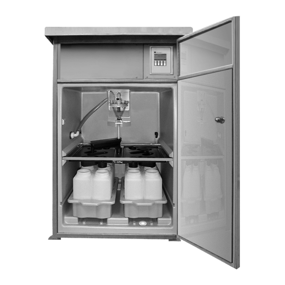
1. Descrizione del sistema 1. Descrizione del sistema Immagine d’insieme (vds. pag. 92) 1 Tubo di aspirazione(a sinistra) 5 Vassoio con bottiglie 2 Sistema di dosaggio con bicchiere dosatore 6 Controllo 3 Beccuccio di distribuzione(solo con distribuz. camp.)7 Vano di connessione (sotto il tettuccio) 4 Pannello di distribuzione (solo con 12 o 24 bottiglie) 8 Dotazioni elettriche opzionali Principio del vuoto... -
Seite 171: Installazione Meccanica
2. Installazione meccanica 2. Installazione meccanica Controllare che la bolla di consegna corrisponda al contenuto della fornitura. Fornitura completa Consultare la targhetta informativa fissata sul lato sinistro del vano di campionamento. Verificare che l’imballaggio ed il contenuto non presentino danni visibili. In caso di Danni di trasporto danni, informare immediatamente sia il trasportatore che il fornitore. -
Seite 172: Connessioni Idrauliche
2. Installazione meccanica 2.5 Connessioni idrauliche • Altezza max. di aspirazione: Campionamento 6 m o 8 m (vds. i codici d’ordine) standard • Lungh. max. del tubo flessibile: 30 m • Posizione delle connessioni: a sinistra o dal basso (vds. codici d’ordine) •... - Seite 173 2. Installazione meccanica Se possibile, porre il tubo di aspirazione in direzione del flusso. • Armatura ad immersione:l’armatura ad immersione è facilmente regolabile e fissa Accessori utili per il punto di aspirazione. l’aspirazione • Filtro ad aspirazione: rimuove particelle solide grosse e ostruzioni. A = Filtro B = Connettore C= Fascetta per tubo...
-
Seite 174: Connessioni Elettriche
3. Connessioni elettriche 3. Connessioni elettriche • Prima di installare l’unità, controllare che la tensione di alimentazione di rete corrisponda a quella indicata sulla targhetta informativa dell’unità. • Se ci sono motivi per dubitare che l’unità funzioni in condizioni di sicurezza (ad es. per danni visibili), si deve spegnere immediatamente e rimuovere dal punto di installazione, per evitare la messa in funzione accidentale. - Seite 175 3. Connessioni elettriche 3.2 Morsettiere Connessione del cavo • Avvitare i morsetti liberi. • Sezione max. fili: 2,5 mm. • Se i fili hanno una sezione maggiore, installare morsetti corrispondenti. (Guida nel vano delle connessioni). • Prevedere sempre cavi di riserva. •...
-
Seite 176: Ingresso Analogico
3. Connessioni elettriche 3.3 Alimentazione Morsetto Connessione Commento X6/1 Vds. targhetta informativa! X6/2 230V AC; 50 Hz; fusibile installato max. 10 A Connessione Terra PE: La connessione alla terra si trova sulla lamiera di metallo della alla terra cabina vicino alla scheda delle morsettiere 3.4 Ingresso analogico L’ingresso analogico passivo serve per la registrazione continua della portata attuale. - Seite 177 3. Connessioni elettriche Le tre uscite relé si usano per la funzione eventi o controllo, che si imposta via 3.6 Uscite relé software. L’impostazione delle uscite relé si esegue nel menu: Uscita 1 ⇒ ⇒ ⇒ Conf. base Uscite Uscita 2 Uscita 3 Morsetto Connessione...
-
Seite 178: Messa A Punto
4. Messa a punto 4. Messa a punto 4.1 Concetto operativo L’impostazione completa dell’unità si esegue usando i quattro tasti operativi. La funzione di questi tasti è sempre visualizzata sopra ciascuno di essi. Le immissioni si eseguono in relazione al menu visualizzato. Gli elenchi di selezione indicano le singole opzioni di impostazione. - Seite 179 4. Messa a punto Prima di eseguire modifiche, il sistema richiede il codice e la richiesta rimane attiva, Richiesta codice finché si rimane nel menu “IMPOSTA”. Il codice operatore, che è di 4 caratteri, può essere cambiato dall’utente. Se si immette “0000" allora non viene più richiesto alcun codice, tutte le impostazioni sono accessibili e possono essere modificate.
- Seite 180 4. Messa a punto ⇒ Set up Creazione programmi 4.2 Impostazioni Le impostazioni generali dell’unità si eseguono dopo l’installazione iniziale. Nome Ident. unità, p.e. testo 10 caratteri Afflusso, Biologia, Deflusso; Default ASP 2000 Codice Codice di rilascio, vds. richiesta codice (pagina precedente). Data-ora Sottomenu: immettere ora e data attuali, immissione ora legale Data...
-
Seite 181: Impostazioni Di Base
4. Messa a punto Attiva o disattiva il controllo del termostato nel vano campioni. Funzionamento Set di temperatura nel vano campioni °C, impostabile da 0 °C a 20 °C. Set di temp. Lo sbrinamento viene eseguito giornalmente. La durata dipende dalla quantità di Sbrinamento ghiaccio formatasi ed è... - Seite 182 4. Messa a punto Prelievi di campioni con Impostazione Cambia Programma Campiona- ⇒ ⇒ ⇒ ⇒ Shots volumi superiori programmi mento Shots Numero di campioni da prelevare per la sequenza di campionamento (max. 10). Esempio: volume richiesto del campione 1 l, 200 ml impostati nel bicchiere dosatore, sono necessari 5 prelievi.
-
Seite 183: Funzioni Avanzate
4. Messa a punto Campionamento cumulativo per 24 h con distribuzione in 4 bottiglie Campionamento Attenzione: l’ingresso quantità deve essere impostato! proporzionale alla quantità Curva di flusso Nome 24h Quantità Mod. di campion. Quantità Ingresso analogico Unità Quantità Campionamento proporzionale alla quantità p.e. - Seite 184 4. Messa a punto La modalità di distribuzione delle bottiglie (controllo a tempo, numerico o esterno) dipende da questa distribuzione. Esempio applicativo a) 1 gruppo di 15 bottiglie per i programmi principale e di commutazione per gruppi di bottiglie: & 1 gruppo di 9 bottiglie per il programma evento: Distribuzione incorp.: 24 bottiglie Programma principale:...
- Seite 185 4. Messa a punto I campioni devono essere prelevati giornalmente: Commutaz. giornaliera Funzionamento Giorno Tra le 04:00 e le 05:00 T Start 1 04:00 T Stop 1 05:00 Tra le 22:00 e le 23:00 T Start 2 22:00 T Stop 2 23:00 La commutazione avviene ogni settimana alla stessa ora.
- Seite 186 4. Messa a punto Si devono assegnare tempi fissi di riempimento alle bottiglie dei campioni, Esempio: Mod. di Bottiglia 1 Bottiglia 2 Bottiglia 3 Bottiglia ... sincronizzazione tempo+bot.: dalle 00:00 alle 02:00 dalle 02:00 alle 04:00 dalle 04:00 alle 06:00 ..
- Seite 187 4. Messa a punto Per il funzionamento con una coppia di programmi si deve definire quando devono essere attivi il programma principale e quello di commutazione. Questa informazione viene richiesta solo se è stata fatta la selezione “2 programmi” al parametro “Numero”. Impostare il criterio di commutazione tra programma principale e di commutazione.
-
Seite 188: Funzionamento E Manutenzione
5. Funzionamento e manutenzione 5. Funzionamento e manutenzione Per ottenere un campione rappresentativo è assolutamente necessaria una pulizia sistematica. Pulire regolarmente le parti a contatto con il prodotto. Il ciclo di pulizia dipende dalle particolari condizioni dell’applicazione. Controllare regolarmente i seguenti componenti e, se necessario, eseguire una pulizia accurata: pulire le parti in plastica con un detergente, non utilizzare solventi o alcool. - Seite 189 5. Funzionamento e manutenzione 5.2 Stoccaggio dei campioni Contenitore unico => Distribuzione Cambio distribuzione • Estrarre il contenitore unico. • Svitare il cappuccio di protezione dallo zoccolo del connettore. • Spingere il sistema di distribuzione (possibilmente insieme ai pannelli di distribuzione) nella cabina.
- Seite 190 Messaggi/statistiche/individuazione anomalie 6. Messaggi L’attività del campionatore viene segnalata in modi diversi. Finestra dei messaggi Sul display dell’unità di controllo compare una finestra messaggi, che deve essere confermata. Elenco dei messaggi Per accedervi premere il tasto REP nel menu principale. I messaggi sono memorizzati in una memoria ad anello e cioè...
- Seite 191 Messaggi/statistiche/individuazione anomalie Messaggio Finestra messaggi Elenco messaggi Stampante Uni Bit (opzionale) 14:12 11.01. Inizia in automatico 14:12 11.01. Avvio: Prog xx Avvio: Prog xx 14:12 11.01. Fine automatico / cancella 14:12 11.01. Fine: Prog xx Fine: Prog xx 14:12 11.01.98 14:12 11.01.
- Seite 192 Messaggi/statistiche/individuazione anomalie In file Informazioni interne sul software per la diagnostica Preset Attenzione: reset ai valori di default di tutte le impostazioni di programma! Ang.vis. Ottimizza la visibilità del display. Anomalia Possibile causa Rimedio Trasmettitore del segnale difettoso, Controllare la corrente di segnale, il Anomalia: 4-20 mA <...
-
Seite 193: Dati Tecnici
9. Dati tecnici 9. Dati tecnici Aree di applicazione Denominazione ASP-Station 2000 Applicazione Sistema di campionamento automatico per acque di scarico Fabbricante Endress+Hauser Impiego e Principio Principio di campionamento per aspirazione struttura del sistema Stazione di campionamento fissa in cabina d’acciaio inox con... -
Seite 194: Codice D'ordine
10. Codici d'ordine 10. Codici d’ordine Stazione di campionamento fissa ASP-Station 2000 Controllo/Software A 1 Programma B 1 Programma + RS485 C 7 Programma D 7 Programma + RS485 E 7 Programma + proporzionale + RS485 Lingua operativa Tedesco Inglese... - Seite 195 11.Accessori / materiali di consumo 11. Accessori / materiali di consumo Accessori: Codici d’ordine: Base cabina 1.4301/SS 304H RPS20A-SE Base su rotelle e maniglie RPS20A-SD Tubo di aspirazione, 13 mm 51001074 (gomma/nera, L = 3 metro) Tubo di aspirazione, 13 mm 51001075 (gomma/nera, L = 5 metro) Tubo di aspirazione, 13 mm...
- Seite 200 Tel. (09) 8 35 70 90, Fax (09) 8 35 06 19 ❑ Endress+Hauser Ges.m.b.H. Wien Poland Chile Japan ❑ Endress+Hauser Polska Sp. z o.o. ❑ Endress+Hauser Chile Ltd. ❑ Sakura Endress Co. Ltd. Tel. (01) 8 80 56-0, Fax (01) 8 80 56-335 Wroclaw Santiago...