Herunterladen Inhalt Inhalt Diese Seite drucken
Inhaltsverzeichnis

Werbung

Verfügbare Sprachen

Verfügbare Sprachen

Start Line TCE 420
de Instandsetzungsanleitung
Reifenmontiermaschinen
it Istruzioni di riparazione
Monta-smonta pneumatici
en Repair instructions
Tyre changing machines
es Instructions de réparation
Máquinas montaneumáticos

Werbung

Inhaltsverzeichnis
loading

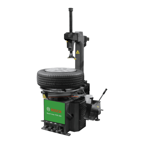
Inhaltszusammenfassung für Bosch Start Line TCE 420

  • Seite 1 Start Line TCE 420 de Instandsetzungsanleitung en Repair instructions es Instructions de réparation Reifenmontiermaschinen Tyre changing machines Máquinas montaneumáticos it Istruzioni di riparazione Monta-smonta pneumatici...
  • Seite 3 | Start Line TCE 420 | 3 Inhalt Deutsch Content English Índice Español Indice Italiano Robert Bosch GmbH 1 695 108 084 2016-11-15...
  • Seite 4 4 | Start Line TCE 420 | Inhalt Deutsch Verwendete Symbolik Sperrzylinder und Dichtungsringe der In der Dokumentation Sechskantwelle ersetzen 1.1.1 Warnhinweise – Aufbau und Bedeutung 5 Sperrzylinder und Dichtungsringe der 1.1.2 Symbole – Benennung und Bedeutung 5 Vierkantwelle ersetzen...
  • Seite 5: Verwendete Symbolik

    Verwendete Symbolik | Start Line TCE 420 | 5 Verwendete Symbolik Allgemeine Hinweise Vor Wartungsarbeiten die Warnungen und Anweisungen In der Dokumentation im Handbuch sorgfältig lesen. Es enthält auch wichtige 1.1.1 Warnhinweise – Aufbau und Bedeutung Informationen zu Sicherheit und Betrieb.
  • Seite 6: Regelmäßige Wartung

    6 | Start Line TCE 420 | Regelmäßige Wartung Regelmäßige Wartung WARNUNG Der Regler B hat ab Werk eine Begrenzung. Verwendung und Wartung des Druck- Nicht einen Druck außerhalb des zulässigen luftreglers Wertebereichs einstellen. Der Kunde muss ein Luftsperrventil in das Gerät ein- bauen, bevor das Gerät mit Druck beaufschlagt wird.
  • Seite 7: Muttern An Gerät In Regelmäßigen

    Regelmäßige Wartung | Start Line TCE 420 | 7 Muttern an Gerät in regelmäßigen Dämpfer an den Pedalventilen in re- Zeitabständen anziehen gelmäßigen Zeitabständen reinigen Die folgenden Arbeiten mindestens einmal alle 30 Tage durchführeni: GEFAHR ¶ Schrauben festziehen, um den Drehteller zu fixie- Vor dem Betrieb die Strom- und Druckluftver- ren.
  • Seite 8: Einrichtung Des Geräts

    8 | Start Line TCE 420 | Einrichtung des Geräts Einrichtung des Geräts Vierkant-Sicherungsplatte justieren Winkel des Montagekopfes einstellen Kann die Vierkantwelle nicht mehr festgestellt wer- 1. 16er oder 17er Felge auf Drehteller aufspannen. den, muss die Sicherungsplatte eingestellt werden.
  • Seite 9: Feststellschrauben Und -Muttern Unten Am Schwenkarm Justieren

    Einrichtung des Geräts | Start Line TCE 420 | 9 Feststellschrauben und -muttern un- Stellung der Pedalventilstange des ten am Schwenkarm justieren Drehtellerzylinders einstellen Hat der Schwenkarm zu viel Spiel, muss die Schrau- Die Stellung der Pedalventilstange ist falsch, so dass be unten am Schwenkarm nachgestellt werden.
  • Seite 10: Dämpfer Oben Am Schwenkzylinderventil Einstellen

    10 | Start Line TCE 420 | Einrichtung des Geräts ¶ Dämpfer oben am Schwenkzylinder- Wenn A und C die Felge nicht berühren können, die ventil einstellen exzentrische Buchse 1 so justieren, dass sich die Spannklauen A und C in der in der Abbildung gezeig- Der Dämpfer muss nachgestellt werden, wenn der...
  • Seite 11: Motorriemen Einstellen

    Einrichtung des Geräts | Start Line TCE 420 | 11 4.12 Motorriemen einstellen Abbildung gezeigten Richtung bewegen (oder nur eine Spannklaue einstellen). Rutscht der Riemen durch, so muss er eingestellt werden. 1. Seitenwand demontieren. 2. Muttern A und B einstellen.
  • Seite 12: Austausch Von Komponenten

    12 | Start Line TCE 420 | Austausch von Komponenten Austausch von Komponen- Wulstabdrückzylinder und Dichtungs- ringe ersetzen 5.2.1 Wulstabdrückzylinder wechseln 1. Befestigungsschraube A und Mutter B entfernen, GEFAHR dann den Zylinder herausnehmen. Vor irgendwelchen Reparatur- oder Wartungs- 2. Schlauch wie vorher anschließen.
  • Seite 13: Schwenkzylinder Und Dichtungsringe Austauschen

    Austausch von Komponenten | Start Line TCE 420 | 13 Schwenkzylinder und Dichtungsringe Sperrzylinder und Dichtungsringe der austauschen Sechskantwelle ersetzen 5.3.1 Schwenkzylinder austauschen 1. Abdeckung und Sicherungsplatte der Sechskantwel- 1. Splinte, die den Zylinder fixieren, entfernen, dann le abnehmen und dann Zylinder oder Dichtungsringe die Stiftwelle herausnehmen.
  • Seite 14: Luftverteiler Und Dichtungsringe Ersetzen

    14 | Start Line TCE 420 | Austausch von Komponenten Luftverteiler und Dichtungsringe Auslassventil und Dichtungsringe ersetzen ersetzen 1. Schläuche abklemmen. 5.9.1 Auslassventil ersetzen 1. Auslassventil A entfernen und durch neues ersetzen. 2. Schlauch wie vorher anschließen. 2. Drehteller entfernen.
  • Seite 15: Schalter Wechseln

    Austausch von Komponenten | Start Line TCE 420 | 15 5.11 Schalter wechseln 5.13 Motor austauschen ¶ 40 A-Schalteranschluss 1. Riemen entfernen. Leistungskabel: 1, 3 2. Schalter ausbauen. Motorkabel: Masseleitung – 12, rot – 10, blau – 9, 3. Schraube A lösen, dann Motor und Motorabstützung schwarz –...
  • Seite 16: Fehlersuche Und -Behebung

    16 | Start Line TCE 420 | Fehlersuche und -behebung Fehlersuche und -behe- ¶ Motor oder Kondensator austauschen. Siehe Ab- bung schnitt "Kondensator austauschen" oder Abschnitt "Motor austauschen". Spannklauen bewegen sich nicht GEFAHR oder nicht ohne Widerstand Vor irgendwelchen Reparatur- oder Wartungs- arbeiten die Strom- und Druckluftversorgung Ist der Zylinder undicht.
  • Seite 17 Fehlersuche und -behebung | Start Line TCE 420 | 17 ¶ Spannklauen bewegen sich von Drehteller locker, Befestigungsschrauben anziehen. selbst Siehe Abschnitt "Muttern an Gerät in regelmäßigen Zeitabständen anziehen". Die Spannklauen bewegen sich von selbst, wenn das Stellung des Montagekopfes nach der Pedal in Mittelstellung ist.
  • Seite 18: Wulstabdrückung Ohne Kraft

    18 | Start Line TCE 420 | Fehlersuche und -behebung 6.12 Schwenkarm bewegt sich nicht oder 6.14 Wulstabdrückung ohne Kraft ¶ zu langsam Druck der Luftversorgung prüfen, gegebenenfalls ¶ Druck der Luftversorgung prüfen, gegebenenfalls den richtigen Druck einstellen. den richtigen Druck einstellen.
  • Seite 19: Umgang Mit Öl

    Umgang mit Öl | Start Line TCE 420 | 19 Umgang mit Öl Nicht inhalieren, schlucken, in die Augen spritzen, in Kontakt mit der Haut kommen lassen etc. Umgang mit Altöl: flüchtiges Öl nicht in die Luft ab- geben, in die Kanalisation oder direkt in ein Gewäs- Einsatz von Feuerlöschmitteln...
  • Seite 20: Übersichtsschaltplan Pneumatik

    20 | Start Line TCE 420 | Übersichtsschaltplan Pneumatik Übersichtsschaltplan Pneu- matik Rif. Designation Komponenten der Wartungseinheit Wasserabscheider Reduzierventil Nebelöler Steuerluftkreis für Querarmsperre Pedalventil für Standsäule Sperrzylinder für Vierkantwelle (hinten) Sperrzylinder für Sechskantwelle Drosselventil Sperrzylinder für Vierkantwelle (vorne) Steuerluftkreis für Schwenkzylinder Pedalventil für Schwenkzylinder...
  • Seite 21 Stromlaufplan | Start Line TCE 420 | 21 Stromlaufplan Robert Bosch GmbH 1 695 108 084 2016-11-15...
  • Seite 22 22 | Start Line TCE 420 | Stromlaufplan 1 695 108 084 2016-11-15 Robert Bosch GmbH...
  • Seite 23 Stromlaufplan | Start Line TCE 420 | 23 Robert Bosch GmbH 1 695 108 084 2016-11-15...
  • Seite 24 24 | Start Line TCE 420 | Content English Symbols used Change square shaft locking cylinder and In the documentation sealing rings 1.1.1 Warning notices - Change the handle valve and sealing rings Structure and meaning Change the air guider and sealing rings 1.1.2...
  • Seite 25: Symbols Used

    Symbols used | Start Line TCE 420 | 25 Symbols used General principles It’s necessary to read the warning and instructions in In the documentation this manual carefully before maintain the equipment, to 1.1.1 Warning notices - Structure and meaning...
  • Seite 26 26 | Start Line TCE 420 | Maintenance routine Maintenance routine WARNING The knob B on adjust valve is limited before Air regulator usage and maintain the machines leave factory. Do not adjust the pressure out of correct range. Customer must install an air stop valve before air into equipment.
  • Seite 27 Maintenance routine | Start Line TCE 420 | 27 Tighten the nuts on equipment at Clean the silencer on pedal valves regular intervals at regular intervals Do the below operation at least every 30 days: ¶ Tighten the bolts to fix the turntable.
  • Seite 28 28 | Start Line TCE 420 | Equipment adjustment Equipment adjustment Adjust the square locking plate Adjust the angle of demounting head The square shaft cannot be locked then need to 1. Clamp the 16" or 17" rim onto the turntable.
  • Seite 29 Equipment adjustment | Start Line TCE 420 | 29 Adjust fixing bolts and nuts at the Adjust the position of pedal valve rod lower end of tilt arm for turntable cylinder Need to adjust the bolt at lower end of tilt arm The valve rod position is not correct to cause the when the tilt arm has oversize swing.
  • Seite 30 30 | Start Line TCE 420 | Equipment adjustment ¶ Adjust the silencer at top of tilt If A and C side cannot touch the rim, adjust the cylinder valve eccentric bushing 1 to move the clamps A & C to the...
  • Seite 31 Equipment adjustment | Start Line TCE 420 | 31 ¶ 4.12 Adjust the motor belt The dial indicator (or demounting head) is nearer to B or D side than adjust the eccentric bushing 1 to move it like picture. Need to adjust the belt when belt slips.
  • Seite 32 32 | Start Line TCE 420 | Change the components Change the components Change bead break cylinder and sealing rings DANGER 5.2.1 Change bead break cylinder Cut off the air source before operation. 1. Remove the fixing bolt A and nut B then take out Exhaust the rest air in equipment by step the the cylinder.
  • Seite 33: Change The Sealing Rings In Cylinder

    Change the components | Start Line TCE 420 | 33 Change tilt cylinder and sealing rings Change hex shaft locking cylinder and sealing rings 5.3.1 Change tilt cylinder 1. Remove the cotters to fix the cylinder then take 1. Remove the cover and hex locking plate then away the pin shaft.
  • Seite 34 34 | Start Line TCE 420 | Change the components Change the air guider and sealing Change exhaust valve and sealing rings rings 1. Disconnect the hose. 5.9.1 Change the exhaust valve 1. Remove the exhaust valve A and change it.
  • Seite 35 Change the components | Start Line TCE 420 | 35 5.11 Change the switch 5.13 Change motor ¶ 40A switch connection 1. Remove the belt. Power cable: 1, 3 2. Remove the switch. Motor cable: Ground wire—12, red—10, blue—9, black—5 3.
  • Seite 36 36 | Start Line TCE 420 | Trouble Trouble Clamps not move or moves not smoothly DANGER Cylinder leaks. ¶ Cut off the air source before operation. Change the cylinder or sealing rings. Exhaust the rest air in equipment by step the Air guider leaks.
  • Seite 37 Trouble | Start Line TCE 420 | 37 The clamps move automatically The position of demounting head has change when tilt arm returns back ¶ The clamps can move automatically when the pedal Hex shaft can’t be locked and need to adjust the valve of turntable cylinder is at the middle position.
  • Seite 38: Oil Usage

    38 | Start Line TCE 420 | Oil usage Oil usage The silencer at top of pedal valve is leaking. Do the steps as follows: 1. Seal the both hoses at front and back of pedal val- Waste oil treat: Do not expose the volatilizable oil ve at the same time, if no air leak, there’s leaking in...
  • Seite 39 Pneumatic schematic dia- gram | Start Line TCE 420 | 39 Pneumatic schematic dia- Forbid to inhale, swallow, splash in eye, contact gram skin and so on. Fire-fighting equipment usage Ref. Designation Air treatment components Solid matter Liquid subs- Electrical...
  • Seite 40: Circuit Diagram

    40 | Start Line TCE 420 | Circuit diagram Circuit diagram 1 695 108 084 2016-11-15 Robert Bosch GmbH...
  • Seite 41 Circuit diagram | Start Line TCE 420 | 41 Robert Bosch GmbH 1 695 108 084 2016-11-15...
  • Seite 42 42 | Start Line TCE 420 | Índice Español Símbolos empleados Sustitución del cilindro de bloqueo y de las En la documentación juntas anulares del eje cuadrado 1.1.1 Advertencias: estructura y significado 43 Sustitución del mango de la válvula y de las 1.1.2...
  • Seite 43: Símbolos Empleados

    Símbolos empleados | Start Line TCE 420 | 43 Símbolos empleados Indicaciones generales Antes de realizar los trabajos de mantenimiento es im- En la documentación prescindible leer las advertencias e instrucciones del 1.1.1 Advertencias: estructura y significado manual. Este también incluye información importante Las indicaciones de advertencia advierten de peligros sobre la seguridad y el mantenimiento.
  • Seite 44: Mantenimiento Regular

    44 | Start Line TCE 420 | Mantenimiento regular Mantenimiento regular ADVERTENCIA El regulador B tiene una limitación de fábrica. Uso y mantenimiento del regulador No ajustar una presión que se sitúe fuera del de aire comprimido rango de valores permitidos.
  • Seite 45 Mantenimiento regular | Start Line TCE 420 | 45 Apretar las tuercas del equipo a in- Limpiar el amortiguador situado en tervalos regulares las válvulas del pedal a intervalos regulares Los siguientes trabajos se deben efectuar como míni- mo una vez cada 30 días: ¶...
  • Seite 46: Instalación De La Máquina

    46 | Start Line TCE 420 | Instalación de la máquina Instalación de la máquina Ajustar la placa de seguridad cuadra- Ajustar el ángulo del cabezal de mon- taje Se deberá ajustar la placa de seguridad. 1. Tensar la llanta 16ª o 17ª en la base giratoria.
  • Seite 47 Instalación de la máquina | Start Line TCE 420 | 47 Ajustar los tornillos y tuercas de Ajuste de la posición del vástago de fijación en la parte inferior del brazo la válvula del pedal del cilindro de la giratorio...
  • Seite 48 48 | Start Line TCE 420 | Instalación de la máquina ¶ Ajustar el amortiguador superior si- Si A y C no pueden tocar la llanta, ajustar el casqui- tuado en la válvula del cilindro osci- llo excéntrico 1 de forma que las garras tensoras A lante y C se muevan en la dirección que se muestra en la...
  • Seite 49 Instalación de la máquina | Start Line TCE 420 | 49 4.12 Ajustar la correa del motor muevan en la dirección que se muestra en la figura (o ajustar únicamente una garra tensora). Si la correa se desliza, habrá que ajustarla.
  • Seite 50: Sustitución De Componentes

    50 | Start Line TCE 420 | Sustitución de componentes Sustitución de componen- 5.1.3 Sustitución de la junta anular interior 1. Limpiar los componentes y engrasar las superficies con grasa lubricante. 2. Alinear la tapa del cilindro e introducir el conector...
  • Seite 51 Sustitución de componentes | Start Line TCE 420 | 51 Sustitución del cilindro oscilante y de Sustitución del cilindro de bloqueo y las juntas anulares de las juntas anulares del eje hexago- 5.3.1 Sustitución del cilindro oscilante 1. Extraer los pasadores que fijan el cilindro y, a conti- 1.
  • Seite 52 52 | Start Line TCE 420 | Sustitución de componentes Sustitución del distribuidor de aire Sustitución de la válvula de descarga y de las juntas anulares y de las juntas anulares 1. Desembornar las tuberías flexibles. 5.9.1 Sustituir la válvula de descarga 1.
  • Seite 53 Sustitución de componentes | Start Line TCE 420 | 53 5.11 SCambiar el interruptor 5.13 Cambiar el motor ¶ Conexión del interruptor 40 A 1. Retirar la correa. Cable de potencia: 1, 3 2. Desmontar el interruptor. Cable del motor: cable de masa – 12, rojo – 10, azul –...
  • Seite 54 54 | Start Line TCE 420 | Búsqueda y reparación de errores Búsqueda y reparación de La el suministro de corriente es irregular. ¶ errores Controlar la red eléctrica. ¶ Cambiar el motor o el condensador. Véase el apar- tado "Cambiar el condensadore" o " Cambiar el PELIGRO motor".
  • Seite 55 Búsqueda y reparación de errores | Start Line TCE 420 | 55 Las garras tensoras se mueven por sí El cabezal de montaje se desgasta solas con demasiada rapidez ¶ Ya no se puede fijar el eje hexagonal y se deberá...
  • Seite 56 56 | Start Line TCE 420 | Búsqueda y reparación de errores 6.12 El brazo giratorio no se mueve o lo 6.14 Destalonamiento sin fuerza ¶ hace con demasiada lentitud Comprobar la presión del suministro de aire; ajustar ¶ Comprobar la presión del suministro de aire; ajustar la presión correcta en caso necesario.
  • Seite 57 Manejo del aceite | Start Line TCE 420 | 57 Manejo del aceite No inhalar, tragar, salpicar en los ojos, poner en contacto con la piel, etc. Manipulación de aceite usado: no dejar el aceite volátil al aire, en la canalización ni introducirlo en las Uso de extintores aguas.
  • Seite 58 58 | Start Line TCE 420 | Esquema sinóptico de los circuitos de conexión del sistema neumático Esquema sinóptico de los circuitos de conexión del sistema neumático Rif. Designation Componentes de la unidad de mantenimiento Separador de agua Válvula reductora...
  • Seite 59: Esquema Eléctrico

    Esquema eléctrico | Start Line TCE 420 | 59 Esquema eléctrico Robert Bosch GmbH 1 695 108 084 2016-11-15...
  • Seite 60 60 | Start Line TCE 420 | Esquema eléctrico 1 695 108 084 2016-11-15 Robert Bosch GmbH...
  • Seite 61 Esquema eléctrico | Start Line TCE 420 | 61 Robert Bosch GmbH 1 695 108 084 2016-11-15...
  • Seite 62 62 | Start Line TCE 420 | Indice Italiano Simboli utilizzati Sostituire il cilindro di bloccaggio e gli anelli Nella documentazione di tenuta dell'albero esagonale 1.1.1 Indicazioni di avvertimento – Sostituire il cilindro di bloccaggio e gli anelli struttura e significato di tenuta dell'albero quadrato 1.1.2...
  • Seite 63: Simboli Utilizzati

    Simboli utilizzati | Start Line TCE 420 | 63 Simboli utilizzati Avvertenze generali Prima dei lavori di manutenzione leggere accuratamente Nella documentazione le avvertenze e le istruzioni d'uso nel manuale. Contie- 1.1.1 Indicazioni di avvertimento – ne anche informazioni importanti relative alla sicurezza struttura e significato e all'esercizio.
  • Seite 64: Manutenzione Regolare

    64 | Start Line TCE 420 | Manutenzione regolare Manutenzione regolare AVVERTENZE Il regolatore B è dotato, di fabbrica, di una Utilizzo e manutenzione del regolato- limitazione. Non impostare una pressione al re dell'aria compressa di fuori dell'intervallo di valori ammesso.
  • Seite 65: Serrare I Dadi Sull'apparecchio A Intervalli Regolari

    Manutenzione regolare | Start Line TCE 420 | 65 Serrare i dadi sull'apparecchio a in- Pulire gli ammortizzatori sulle valvole tervalli regolari del pedale a intervalli regolari Eseguire i seguenti interventi una volta ogni 30 giorni: ¶ Serrare le viti, per fissare il piatto rotante.
  • Seite 66 66 | Start Line TCE 420 | Allestimento dell'apparecchio Allestimento dell'apparec- Regolare la piastra di sicurezza qua- drata chio La piastra di sicurezza deve essere impostata. Impostare l'angolare dell'utensile di montaggio L'albero quadrato può essere spostato all'indietro di 1. Tensionare il 16° o il 17° cerchione sul piatto rotan- 2-3 mm e poi bloccato.
  • Seite 67 Allestimento dell'apparecchio | Start Line TCE 420 | 67 it it Regolare le viti e i dadi di fissaggio in Impostare la posizione dell'asta della basso sul braccio orientabile valvola del pedale del cilindro del piatto rotante Se il braccio orientabile dispone di troppo gioco, deve essere regolata la vite al di sotto del braccio La posizione dell'asta della valvola del pedale è...
  • Seite 68 68 | Start Line TCE 420 | Allestimento dell'apparecchio ¶ Impostare l'ammortizzatore in alto Se A a C non riescono a toccare il cerchione, re- sulla valvola del cilindro orientabile golare la boccola eccentrica 1 in modo tale che le griffe di bloccaggio A e C si muovano nella direzione L'ammortizzatore deve essere regolato, se non è...
  • Seite 69 Allestimento dell'apparecchio | Start Line TCE 420 | 69 it it 4.12 Impostare la cinghia del motore muovano nella direzione indicata in figura (o impo- stare una sola griffa di bloccaggio). Se la cinghia scivola, allora deve essere impostata. 1. Smontare la fiancata.
  • Seite 70: Sostituzione Dei Componenti

    70 | Start Line TCE 420 | Sostituzione dei componenti Sostituzione dei compo- 5.1.3 Sostituire gli anelli di tenuta interni nenti 1. Pulire i componenti e lubrificare la superficie con grasso lubrificante. 2. Allineare il coperchio del cilindro ed innestare con PERICOLO corretta polarità...
  • Seite 71 Sostituzione dei componenti | Start Line TCE 420 | 71 it it Sostituire il cilindro orientabile e gli Sostituire il cilindro di bloccaggio e anelli di tenuta gli anelli di tenuta dell'albero esago- nale 5.3.1 Change tilt cylinder 1. Rimuovere le copiglie, che fissano il cilindro, poi 1.
  • Seite 72 72 | Start Line TCE 420 | Sostituzione dei componenti Sostituire il distributore dell'aria e gli Sostituire la valvola di scarico e gli anelli di tenuta anelli di tenuta 1. Scollegare i tubi flessibili. 5.9.1 Sostituire la valvola di scarico 1.
  • Seite 73 Sostituzione dei componenti | Start Line TCE 420 | 73 it it 5.11 Sostituire l’interruttore 5.13 Sostituire il motore ¶ Collegamento dell'interruttore 40A 1. Rimuovere la cinghia. Cavo di potenza: 1, 3 2. Smontare l'interruttore. Cavo motore: cavo di massa–12, rosso–10, blu–9, 3.
  • Seite 74 74 | Start Line TCE 420 | Ricerca e rimozione degli errori Ricerca e rimozione degli Le griffe di bloccaggio non si muovo- no o non senza resistenza errori Se il cilindro non è a tenuta. ¶ Costituire il cilindro o gli anelli di tenuta.
  • Seite 75 Ricerca e rimozione degli errori | Start Line TCE 420 | 75 it it ¶ Le griffe di bloccaggio si muovono Se l'albero quadrato dispone di troppo gioco, deve autonomamente essere regolata la vite al di sotto del rullo. Vedere paragrafo "Regolare il rullo dell'albero quadrato".
  • Seite 76 76 | Start Line TCE 420 | Ricerca e rimozione degli errori 6.12 Il braccio orientabile non ruota o ruo- 6.14 Stallonatura senza forza ¶ ta troppo lentamente Controllare la pressione dell'alimentazione dell'aria, ¶ Controllare la pressione dell'alimentazione dell'aria, eventualmente impostare la pressione corretta.
  • Seite 77 Gestione dell'olio | Start Line TCE 420 | 77 it it Gestione dell'olio Non inalare, ingerire, spruzzare negli occhi, venire in contatto con la pelle ecc.. Gestione dell'olio usato: non disperdere l'olio vola- tile nell'aria, nella canalizzazione o non scaricarlo Impiego di estintori direttamente nell'acqua.
  • Seite 78 78 | Start Line TCE 420 | Schema panoramico dell'impianto pneumatico Schema panoramico dell'impianto pneumatico Rif. Designation Componenti dell'unità di manutenzione Separatore d'acqua Valvola riduttrice Nebulizzatore d'olio Circuito dell'aria di pilotaggio per il blocco del braccio tra- sversale...
  • Seite 79: Schema Elettrico

    Schema elettrico | Start Line TCE 420 | 79 it it Schema elettrico Robert Bosch GmbH 1 695 108 084 2016-11-15...
  • Seite 80 80 | Start Line TCE 420 | Schema elettrico 1 695 108 084 2016-11-15 Robert Bosch GmbH...
  • Seite 81 Schema elettrico | Start Line TCE 420 | 81 it it Robert Bosch GmbH 1 695 108 084 2016-11-15...
  • Seite 82 Robert Bosch GmbH Automotive Service Solutions Franz-Oechsle-Straße 4 73207 Plochingen DEUTSCHLAND www.bosch.com bosch.prueftechnik@bosch.com 1 695 108 084 | 2016-11-15...

Inhaltsverzeichnis