Herunterladen Inhalt Inhalt Diese Seite drucken

Werbung

Verfügbare Sprachen

Verfügbare Sprachen

WBE 4140
de Instandsetzungsanleitung
Reifenmontiermaschine
it Istruzioni di riparazione
Smontagomme
en Repair instructions
Tire changer
es Instructions de réparation
Machine à monter les pneus

Werbung

Inhaltsverzeichnis
loading

Inhaltszusammenfassung für Bosch WBE 4140

  • Seite 1 WBE 4140 de Instandsetzungsanleitung en Repair instructions es Instructions de réparation Reifenmontiermaschine Tire changer Machine à monter les pneus it Istruzioni di riparazione Smontagomme...
  • Seite 2 2 | WBE 4140 | 1 695 655 779 2010-11-9 Robert Bosch GmbH...
  • Seite 3 | WBE 4140 | � WBE 4140 | � | � Inhaltsverzeichnis Deutsch � Contents English Índice Español Indice Italiano Robert Bosch GmbH 1 695 655 779 2010-11-9...
  • Seite 4: Inhaltsverzeichnis Deutsch

    | WBE 4140 | � Inhaltsverzeichnis Deutsch Verwendete Symbolik 8.6.1 Radschutzabdeckung-Mikroschalter In der Dokumentation 1.1.1 Warnhinweise – Aufbau und Bedeutung 4 Wechsel von Komponenten 1.1.2 Symbole – Benennung und Bedeutung 4 Ersatz des Pick-ups Auswechslung Easy Aludata Lehre WBE 4140 Prozedur für die Positionierung des Potentiome-...
  • Seite 5: Verwendete Symbolik

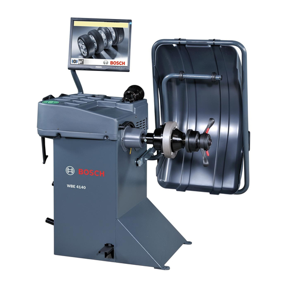
    4 | WBE 4140 | Verwendete Symbolik Verwendete Symbolik Auf dem Produkt In der Dokumentation Alle Warnzeichen auf den Produkten beachten und in 1.1.1 Warnhinweise – Aufbau und Bedeutung lesbarem Zustand halten! Warnhinweise weisen auf Gefahren und deren Folgen für den Benutzer oder umstehende Personen hin.
  • Seite 6 WBE 4140 | WBE 4140 | 5 WBE 4140 Fig. 1: WBE 4140 Pos. Bezeichnung Funktion/was ich damit tun kann TFT-Monitor Anzeige Software (Messwerte und Bedienhinweise). R Schutz des Bedieners vor wegfliegenden Partikeln (z. B. Schmutz, Wasser). Radschutzhaube R Messung starten und Messung stoppen, siehe Kap. 8.3.3 Messarm (Zubehör)
  • Seite 7: Benutzung Der Menüs

    6 | WBE 4140 | Maschinenbetrieb und Benutzung der Menüs Maschinenbetrieb und �.� Navigazione menù Benutzung der Menüs Das Menü der Auswuchtmaschine kann in verschiedene Untermenüs untergliedert werden: �.1 Display Aufruf Service-Menü (nur für den Kundendienst) Die Initialisierung der Software wird ca. 20 Sekunden nach dem Einschalten von WBE 4140 Aufruf des Kalibrier-Menüs...
  • Seite 8 Maschinenbetrieb und Benutzung der Menüs | WBE 4140 | 7 �.�.� Einstellungen Aktiviert oder deaktiviert den Messschieber und den Messarm. < > drücken, um zur vorherigen Seite zurückzukehren. Positionierung des Klebegewichtes (elektronischer Messschieber, manueller Messschieber (3, 6 oder 12 Uhr).
  • Seite 9: Störungen

    Technikern überprüft und gegebenenfalls behoben werden. Wenden Sie sich in jedem Fall an den Kundendienst des befugten Händlers der Bosch-Ausstattungen. Für eine schnelle Abhilfe ist es wichtig, beim Anruf die Angaben auf dem Typenschild (Etikett auf WBE 4140) und die Art der Störung anzugeben.
  • Seite 10 1. Nicht auf das Pedal drücken, wenn der Motor in Be- trieb ist: 2. Drehgeschwindigkeit des Motors ist unregelmäßig. 2. Darauf achten, dass WBE 4140, während der Messung, keinen Stößen ausgesetzt ist. 3. Radgeschwindigkeit unter dem Mindestwert. 3. Netzspannung kontrollieren (wahrscheinlich zu niedrig).
  • Seite 11 10 | WBE 4140 | Prozedur für Softwareaktualisierung Prozedur für Kartenkonfiguration Softwareaktualisierung Die Karte wird während der Installation konfiguriert, indem zur Eingabe eines Aktivierungscodes Die von SICAM eingeführte neue Generation von aufgefordert wird, mit dem die wichtigsten Merkmale Karten basiert auf einer Windows CE Umgebung.
  • Seite 12 Zustand (z.B. Breite 5.5", Durchmesser Kalibrierung der elektronischen 14") am Flansch befestigen. Schieblehre/der Winkellehre zur Breitenmessung 2. Kalibrierung WBE 4140 wählen und mit <OK> bestätigen. Befolgen Sie die angezeigten Hinweise auf dem Monitor. 1. Kalibrierung der elektronischen Schieblehre und der ...
  • Seite 13 12 | WBE 4140 | Standardkalibrierung  Die Kalibrierung wird gestattet. 2. Die Schieberegler des Abstands A und der Breite B in Ruhestellung bringen und <OK> drücken. 7. Den Stift abmontieren und eine Probefelge aus Stahl zu 14” oder 15” mit der entsprechenden Anzugmutter montieren.
  • Seite 14: Factory-Kalibrierung

    Factory-Kalibrierung und bestätigen mit <OK>. 5. Radschutzhaube schließen.  Messung wird gestartet.  WBE 4140 muss auf dieser Seite genau diese Unwucht (Wert und Position) anzeigen. Für die andere Seite darf die Angabe höchstens 5 g 2. Passwort eingeben: <z> <u> <v>.
  • Seite 15 14 | WBE 4140 | Standardkalibrierung 5. Das Probegewicht an der Innenseite des Flanschs anbringen. 6. <START> drücken oder die Radschutzhaube schließen.  Die Messung wird gestartet. 7. Das Probegewicht von der Innenseite des Flanschs entfernen und an der Außenseite anbringen (12-Uhr- Position).
  • Seite 16: Abrufung Des Diagnostikmenüs

    Diagnostik | WBE 4140 | 15 Diagnostik - Kontrolle Kondensatoren und Relais Die Diagnostik kann bei der Wartung verwendet werden, um die verschiedenen Funktionen der WBE 4140 gründlich zu kontrollieren. Dieses Verfahren ist unentbehrlich, um eine Störung der Sensoren festzustellen.
  • Seite 17 16 | WBE 4140 | Diagnostik 1. Zum Selbstdiagnose-Menü gehen (Menü 1). " Auf dem Display erscheinen in Sequenz die von den Pick-up beim letzten Start gelesenen Werte und die Phasendifferenz in Graden. Fig. 8: Position der piezoelektrischen Sensoren Spannungen...
  • Seite 18: Motor Und Leistungskarte

    Diagnostik | WBE 4140 | 17 Fehler Korrektur Das Rad dreht nicht. Die elektrischen Anschlüsse kontrollieren. Den Motor oder die Kondensatoren auswechseln. Der Motor erreicht Die Spannung des dieAuswuchtgesch- Transmissionsriemens windigkeit nicht. kontrollieren. Den Motor oder die Kondensatoren auswechseln. 8.2.�...
  • Seite 19: Wechsel Von Komponenten

    18 | WBE 4140 | Wechsel von Komponenten 8.5.2 Diagnose Breitenpotentiometer (IN�) Bei einer Betriebsstörung des Mikroschalters ist die korrekte Position des Betätigungsnockens des Mikroschalters und der Schalter selbst zu kontrollieren. Fehler Korrektur Wechsel von Komponenten Der Wert bleibt am Ende der...
  • Seite 20: Auswechslung Easy Aludata Lehre

    Wechsel von Komponenten | WBE 4140 | 19 damit die Kugeln an ihrer Position bleiben, etwas 6. und wieder montieren nach der gleichen Prozedur Fett verwenden; wie der Ausbau 9.� Prozedur für die Positionierung des 10. den Gewindestift solange wieder eindrehen, bis er Potentiometers für die Breitenmes-...
  • Seite 21: Auswechslung Des Antriebsriemens

    20 | WBE 4140 | Wechsel von Komponenten Prozedur für die Positionierung des Potentio- 9. die ordnungsgemäße Betriebsweise während des meters für die Durchmessermessung: Verstellwegs des Potentiometers prüfen; 10. die Maschine wieder schließen; 1. nur die Gewichteablage-Abdeckung entfernen, ohne 11. die Prozedur für die Kalibrierung der Messarme dabei die Karte abzutrennen;...
  • Seite 22: Auswechslung Der Leistungskarte

    Empfohlene Ersatzteile und Werkzeuge | WBE 4140 | 21 Auswechslung der Leistungskarte Die piezoelektrischen Sensoren sind identisch; um sie zu unterscheiden, wird bei der Herstellung 1. die Abdeckung mit der Gewichteablage abmontieren; der rote Pick-up außen und der schwarze an 2.
  • Seite 23: Elektrische Anlage

    22 | WBE 4140 | Elektrische Anlage 11. Elektrische Anlage 1 695 655 779 2010-11-9 Robert Bosch GmbH...
  • Seite 24 Elektrische Anlage | WBE 4140 | 2� Robert Bosch GmbH 1 695 655 779 2010-11-9...
  • Seite 25: Contents English

    24 | WBE 4140 | Contents English Symbols used Ingressi ed uscite digitali In the documentation 8.6.1 Protection micro switch 1.1.1 Warning notices - Structure and meaning Replacement interventions �9 1.1.2 Symbols in this documentation Pick-up replacement On the product...
  • Seite 26: Symbols Used

    Symbols used | WBE 4140 | 25 Symbols used On the product In the documentation Observe all warning notices on products and ensure 1.1.1 Warning notices - Structure and meaning they remain legible! Warning notices indicate hazards and their consequences for the user or surrounding persons.
  • Seite 27 R Determination of positions for attachment of adhesive weights. Cone of drive shaft Flange mounting. Pedal Locking of shaft / wheel. Control panel Operation of WBE 4140, refer to Section 7.3 Tray For storing balance weights and accessories. Mains socket Connection for power cord. On/off switch Switching WBE 4140 on and off.
  • Seite 28 How to use the machine and surfing menu | WBE 4140 | 27 How to use the machine �.� Menu navigation and surfing menu We can divide the balancing machine menu in several submenus: �.1 Display Call-up of service menu (customer service only) The initialization of the software is displayed approx.
  • Seite 29 28 | WBE 4140 | How to use the machine and surfing menu �.�.� Settings Activates or deactivates the vernier caliper and the gauge arm. Press <OK> to return to the previous page. Positioning of adhesive weight (electronic vernier caliper, manual vernier caliper (3, 6 or 12 o'clock).
  • Seite 30 Always contact the customer service of your authorized Bosch equipment dealer. To enable action to be taken quickly, it is important to inform customer service of the specifications on the rating plate (label on the flange end of the WBE 4140) and the nature of the problem. Faults...
  • Seite 31 1. Pedal pressed during measurement 1. Do not press pedal whilst motor is in operation. 2. Irregular rotational speed of motor 2. Make sure the WBE 4140 is not subjected to any impact during measurement. 3. Wheel speed below minimum value 3.
  • Seite 32 How to up-to-date the software | WBE 4140 | �1 How to up-to-date the Configuration of the board software The board is configured during the installing. It The new generation of boards used by Sicam works on requires an activation code that determines the main Windows CE;...
  • Seite 33: Standard Calibration

     Measurement is started. We recommend carrying out the standard calibration 5. Enter any balancing weight between 40 g and 120°g of WBE 4140 during commissioning, during the six- and confirm by pressing <OK>. monthly maintenance operations or in the presence 6.
  • Seite 34 Standard calibration | WBE 4140 | �� 2. Move the slides with distance A and width B to standby position and press <OK>. 7. Remove the pin and assemble a 14'' or 15'' steel sample wheel using the relevant hold-down nut.
  • Seite 35: Factory Calibration

    1. From the "Settings and Service" menu select  Measurement commences. Calibration and confirm by pressing <OK>.  The WBE 4140 must display precisely this unbalance (value and position) on this side. The value indicated for the other side must not exceed 5 g.
  • Seite 36 Standard calibration | WBE 4140 | �5 5. Apply the sample weight on the internal side of the flange. 6. Press <START> or close the wheel protection cap..  Measurement is started. 7. Remove the sample weight from the internal side of the flange and apply it on the external side (12 o'clock).
  • Seite 37 �6 | WBE 4140 | Diagnostics Diagnostics - Check relay condensers The diagnostics can be used during after-sales assistance for an in-depth check of the various functions of the WBE 4140. This procedure is essential to identify a malfunctioning of the sensors.
  • Seite 38 Diagnostics | WBE 4140 | �7 2. Fix the wheel of a motor vehicle of average size and Fig. 8: Position of the piezo-electric sensors in excellent conditions (e.g. 5.5" wide, 14" diameter) Voltages on to the flange and carry out a perfect balancing.
  • Seite 39 �8 | WBE 4140 | Diagnostics The engine does Check the tensioning of the not reach the transmission belt. balancing speed Replace the engine or the condensers. The wheel does Check, and eventually replace, the not brake (in power board.
  • Seite 40 Replacement interventions | WBE 4140 | �9 Replacement interventions The value remains blocked Check that the ring nut is between 100 and 16000. correctly fixed. Replace the connection Pick-up replacement cable. Replace the potentiometer. 1. Remove the weights protection; 8.5.�...
  • Seite 41 40 | WBE 4140 | Replacement interventions 9.� Width potentiometer positioning 10. Screw the nut until you cannot turn it manually; procedure Manually: lock the nut making a half turn with the key; 1. Remove the left side protection without disconnecting the board;...
  • Seite 42 Replacement interventions | WBE 4140 | 41 Diameter potentiometer positioning procedu- 9. Check the correct functioning during the stroke; 10. Close the machine; 1. Remove only the carter without disconnecting the 11. Proceed with the calibration of gauges (chapter board;...
  • Seite 43 42 | WBE 4140 | Replacement interventions Power board replacement When it is necessary to replace the board, activate the board and perform the various calibration 1. Remove the weights protection; passages. 2. Loosen the 5 rear screws using an allen wrench;...
  • Seite 44: Suggested Spare Parts

    Suggested spare parts | WBE 4140 | 4� 10. Suggested spare parts Fundamental tools for a correct assistance: Allen screws set Screwdriver (crosshead and slotted screwdrivers) Hex key set Tester (multimeter) For spare parts contact AADGT-ASA. Robert Bosch GmbH 1 695 655 779...
  • Seite 45: Electric System

    44 | WBE 4140 | Electric system 11. Electric system MARRONE/BROWN BIANCO/WHITE 1 695 655 779 2010-11-9 Robert Bosch GmbH...
  • Seite 46 Electric system | WBE 4140 | 45 Robert Bosch GmbH 1 695 655 779 2010-11-9...
  • Seite 47: Índice Español

    46 | WBE 4140 | Índice Español Símbolos empleados (IN3) En la documentación 8.5.3 Diagnóstico del potenciómetro del diá- 1.1.1 Advertencias: estructura y significado 47 metro (IN4) 1.1.2 Símbolos en esta documentación Entradas y salidas digitales 8.6.1 Microinterruptor de la cubierta WBE 4140 Operaciones de sustitución...
  • Seite 48: Símbolos Empleados

    Peligro grave en caso de personas debidamente capacitadas bajo la ocurrencia pasarse por alto supervisión de un electricista. PELIGRO Peligro Muerte lesiones ¶ Antes de abrir WBE 4140, separarlo de la físicas inmediato graves red de tensión. Peligro Muerte lesiones físicas amenazante graves ATENCIÓN...
  • Seite 49 48 | WBE 4140 | WBE 4140 WBE 4140 Fig. 1: WBE 4140 Pos. Designación Función/lo que puedo hacer con esto Monitor TFT Visualización software (valores de medición e indicaciones para el manejo). R Protección del operador contra las partículas volantes (p. ej., suciedad, agua).
  • Seite 50 �.2 Teclas de manejo �.�.2 Calibración El WBE 4140 se maneja con la tecla < I > y las teclas de flechas. Las funciones correspondientes están descritas en la tabla 1. Introduzca la contraseña <r> <r> <o>. Calibración con una rueda "en buen estado".
  • Seite 51 50 | WBE 4140 | Funcionamiento y navegación menú �.�.� Ajustes Activa o desactiva la corredera de medición y el brazo de medición. Pulsar < I > para volver a la página anterior. Posicionamiento del peso pegado (corredera de medición electrónica, corredera de medición manual (3, 6 ó...
  • Seite 52 Bosch. Para posibilitar una intervención rápida es importante indicar las especificaciones de la placa de características (etiqueta en el lado de la brida del WBE 4140) y el tipo de fallo al llamar al servicio postventa. Fallos...
  • Seite 53 1. No presionar el pedal mientras el motor está en 2. La velocidad de giro del motor es irregular. marcha: 2. Cerciorarse de que el WBE 4140 no sufra golpes durante la medición. 3. Velocidad de la rueda por debajo del valor mínimo.
  • Seite 54 Procedimiento de actualización del software | WBE 4140 | 5� Procedimiento de Comfiguración de la tarjeta actualización del software La tarjeta viene configurada en fase de instalación pidiendo un código de activación que determina los La nueva generación de tarjetas introducidas por Sicam principales detalles.
  • Seite 55 El desequilibrio se ha establecido en el valor "0". 5.5", diámetro 14") en la brida. Calibración del pie de rey/brazo de medición 2. Seleccione Calibración WBE 4140 y confirme con <OK>. Siga las instrucciones visualizadas en la pantalla.r 1. Seleccionar Calibración del pie de rey y del brazo de medición y confirmar con <OK>.
  • Seite 56 Calibración estándar | WBE 4140 | 55 2. Llevar las correderas de la distancia A y de la 7. Desarmar el perno y colocar una llanta de muestra anchura B a la posición de reposo y apretar <OK>. de acero de 14” o 15” con la tuerca adecuada de apriete.
  • Seite 57 Calibración y confirme con <OK> 5. Cerrar la cubierta protectora de la rueda.  Se inicia la medición.  El WBE 4140 debe indicar en ese lado exactamente ese desequilibrio (valor y posición). Para el otro lado, la indicación debe ser, como 2.
  • Seite 58 Calibración estándar | WBE 4140 | 57 5. Aplique el contrapeso de muestra en el lado interno de la brida. 6. Presione <START> o cierre la carcasa de protección de la rueda.  La medición se pone en marcha. 7. Quite el contrapeso de muestra del lado interno de la brida y aplíquelo en el lado externo (12 horas).
  • Seite 59 58 | WBE 4140 | Diagnóstico Diagnóstico El diagnóstico puede utilizarse en la fase de asistencia para controlar en modo detallado las diferentes funciones del WBE 4140. Este procedimiento es indispensable para localizar una avería de los sensores. Acceso al menú de diagnóstico 1.
  • Seite 60 Diagnóstico | WBE 4140 | 59 2. Fije la rueda de un automóvil de dimensiones Fig. 8: Posición de los sensores piezoeléctricosi medianas y en óptimas condiciones (p. ej. ancho Tensiones 5.5", diámetro 14") en la brida y efectúe un Los sensores piezoeléctricos, según la posición en la...
  • Seite 61 60 | WBE 4140 | Diagnóstico Defecto Corrección La rueda no gira. Controle las conexiones eléctricas. Cambie el motor o los condensadores. El motor no Controle la tensión de la correa de alcanza la transmisión. velocidad de Cambie el motor o los condensadores.
  • Seite 62 Diagnóstico | WBE 4140 | 61 ¶ 8.5.2 Diagnóstico del potenciómetro del ancho Si el microinterruptor presenta problemas, controle (IN�) la posición de la leva de funcionamiento y el mic- rointerruptor mismo, además de la conexión de los cables (véase el esquema eléctrico).
  • Seite 63 62 | WBE 4140 | Operaciones de sustitución Operaciones de sustitución para mantener las esferas en posición utilizar un poco de grasa; Procedimiento ajuste o sustitución pick-up: 10. atornillar la tuerca hasta que no se pueda enroscar más manualmente: 1. Quite la cubierta portapesos;...
  • Seite 64 Operaciones de sustitución | WBE 4140 | 6� 9.� Procedimiento colocación potencime- Procedimiento colocación potenció- metro diámetro; tro anchura: 1. quitar el único cárter portapesos sin desconectar la 1. quitar el único cárter portapesos sin desconectar la tarjeta; tarjeta; 2. encender la equilibradora;...
  • Seite 65 64 | WBE 4140 | Operaciones de sustitución Procedimiento de sustitución de la 9. comprobar el funcionamiento correcto durante el tarjeta potencia recorrido; 10. volver a cerrar la máquina; 11. proceder con la medición de los calibres (capítulo 1. Quitar el único cárter portapesos menú...
  • Seite 66 Recambios e instrumentos aconsejados | WBE 4140 | 65 10. Recambios e instrumentos parte interna. Marque los cables F y G antes de aconsejados volver a conectarlos para poderlos reconocer. Cuando se presenta la necesidad de sustituir la Instrumentos indispensables para una correcta asistencia:...
  • Seite 67: Instalación Eléctrica

    66 | WBE 4140 | Instalación eléctrica 11. Instalación eléctrica 1 695 655 779 2010-11-9 Robert Bosch GmbH...
  • Seite 68 Instalación eléctrica | WBE 4140 | 67 Robert Bosch GmbH 1 695 655 779 2010-11-9...
  • Seite 69 68 | WBE 4140 | Indice Simboli utilizzati 8.5.3 Diagnosi potenziometro del diametro Nella documentazione (IN4) 1.1.1 Indicazioni di avvertimento – struttura e Ingressi ed uscite digitali significato 8.6.1 Microinterruttore carter 1.1.2 Simboli nella presente documentazione Interventi di sostituzione 8�...
  • Seite 70: Simboli Utilizzati

    Simboli utilizzati | WBE 4140 | 69 Simboli utilizzati Sul prodotto Nella documentazione Rispettare tutti i simboli di avvertimento sui prodotti 1.1.1 Indicazioni di avvertimento – struttura e e mantenere le relative etichette integralmente in significato condizioni di perfetta leggibilità! Le indicazioni di avvertimento segnalano pericoli e le relative conseguenze per l’utente o persone...
  • Seite 71 70 | WBE 4140 | WBE 4140 WBE 4140 Fig. 1: WBE 4140 Pos. Denominazione Funzione/cosa posso farci Monitor TFT Visualizzazione software (valori di misura e avvertenze sull’uso) R Protezione dell’operatore da eventuali particelle proi- Calotta di protezione ruota ettate verso l’esterno (ad es. sporco, acqua).
  • Seite 72 Modo d'uso e navigazione menù | WBE 4140 | 71 Modo d'uso e navigazione �.� Navigazione menù menù Si può suddividere il menù dell'equilibratrice in diversi sottomenù: �.1 Display Richiamo menu diagnostica (solo per il servizio assistenza, vedi cap. 8.1) L'inizializzazione del software viene visualizzata ca.20 secondi dopo l'inserimento di WBE 4140.
  • Seite 73 72 | WBE 4140 | Modo d'uso e navigazione menù �.�.� Impostazioni Attiva o disattiva il freno per bloccare la flangia e la ruota. Attiva o disattiva il calibro a corsoio e il braccio di misurazione. Premere <OK> per ritornare alla pagina precedente.
  • Seite 74 Rivolgersi in ogni caso al servizio assistenza del rivenditore autorizzato di equipaggiamenti Bosch. Per velocizzare l’intervento è importante indicare durante la telefonata al servizio assistenza i dati riportati sulla targhetta di identificazione (etichetta sul lato flangia di WBE 4140) e il tipo di guasto. Anomalie Cause Rimedio All’accensione...
  • Seite 75 2. Abbassare la calotta di protezione ruota e riaccen- protezione ruota aperta (l’albero gira a velocità elevata dere la WBE 4140 senza muovere la ruota. senza che la macchina sia stata avviata): l'alimentatore 3. Se il messaggio di errore persiste, è necessario viene disattivato.
  • Seite 76 Procedura di aggiornamento software | WBE 4140 | 75 Procedura di Configurazione scheda aggiornamento software video La nuova generazione di schede introdotta da Sicam lavora in ambiente Windows CE; questo permette al La scheda viene configurata in fase di installazione...
  • Seite 77  La misurazione viene avviata. Si consiglia di effettuare la calibrazione standard 5. Immettere un peso di equilibratura qualsiasi tra 40 g di WBE 4140 durante la prima messa in funzione, e 120 g e confermare con <OK>. nell’ambito degli interventi di manutenzione 6.
  • Seite 78 Calibrazione standard | WBE 4140 | 77 2. Portare i cursori della distanza A e della larghezza B in posizione di riposo e premere <OK>. 7. Smontare il perno e montare un cerchio campione in acciaio da 14” o 15” con l’apposito dado di serraggio.
  • Seite 79 5. Chiudere la calotta di protezione ruota. Calibrazione e confermare con <OK>.  La misurazione viene avviata.  La WBE 4140 deve indicare esattamente questo squilibrio (valore e posizione). Per l’altro lato l’indicazione deve essere al massimo di 5 g.
  • Seite 80 Calibrazione standard | WBE 4140 | 79 5. Applicare il peso campione sul lato interno della flangia. 6. Premere <START> o chiudere la calotta di protezione ruota.  La misurazione viene avviata. 7. Togliere il peso campione dal lato interno della flangia e applicarlo sul lato esterno (ore 12).
  • Seite 81 80 | WBE 4140 | Menù di Auto-diagnosi Menù di Auto-diagnosi - Controllo condensatori e relè La diagnostica può essere utilizzato in fase di assistenza per controllare in modo approfondito le varie funzioni della WBE 4140. Questa procedura è indispensabile per individuare un malfunzionamento dei sensori.
  • Seite 82 Menù di Auto-diagnosi | WBE 4140 | 81 2. Fissare la ruota di un autoveicolo di media Fig. 8: Posizione dei sensori piezo-elettrici dimensione ed in ottime condizioni (ad es. larghezza Tensioni 5.5", diametro 14") sulla flangia ed eseguire una I sensori piezo-elettrici, a seconda della posizione in perfetta equilibratura.
  • Seite 83 82 | WBE 4140 | Menù di Auto-diagnosi Il motore non Controllare la tensione della cinghia di raggiunge la trasmissione. velocità di Sostituire il motore o i condensatori. bilanciatura. La ruota non Controllare ed eventualmente sostituire frena (in contro la scheda di potenza.
  • Seite 84 Interventi di sostituzione | WBE 4140 | 8� Interventi di sostituzione Il valore resta bloccato tra Controllare che la ghiera sia 100 e 16000. fissata correttamente. Sostituire il cavo di Procedura sostituzione pick-up connessione. Sostituire il potenziometro. 1. Rimuovere il carter portatesi;...
  • Seite 85 84 | WBE 4140 | Interventi di sostituzione 9.� Procedura posizionamento potenzio- 10. Avvitare il grano (fig.14, pos.1) finchè non è più possibile ruotare il sensore manualmente: metro larghezza Manualmente: serrare il grano (fig.19,pos.1) facendo un mezzo giro con la chiave;...
  • Seite 86 Interventi di sostituzione | WBE 4140 | 85 Procedura posizionamento potenzio- 9. Controllare il corretto funzionamento durante la metro diametro corsa; 10. Richiudere la macchina; 1. Rimuovere il solo carter portatesi senza scollegare la 11. Procedere con la taratura dei calibri (capitolo menù...
  • Seite 87 86 | WBE 4140 | Interventi di sostituzione Sostituzione scheda potenza Quando si presenta la necessità di sostituire la scheda, attivare la scheda ed eseguire i vari passaggi 1. Rimuovere il carter portapesi; di taratura. 2. Con una chiave a brugola svitare le 5 viti posteriori;...
  • Seite 88: Strumenti Consigliati

    Strumenti consigliati | WBE 4140 | 87 10. Strumenti consigliati Strumenti indispensabili per una corretta assistenza: Set di chiavi a brugola Set cacciaviti (a stella e a taglio) Set chiavi esagonali Tastiera USB Chiave USB per aggiornamenti Tester (multimetro) Robert Bosch GmbH...
  • Seite 89: Impianto Elettrico

    88 | WBE 4140 | Impianto elettrico 11. Impianto elettrico 1 695 655 779 2010-11-9 Robert Bosch GmbH...
  • Seite 90 Impianto elettrico | WBE 4140 | 89 Robert Bosch GmbH 1 695 655 779 2010-11-9...
  • Seite 91 Robert Bosch GmbH Diagnostics Franz-Oechsle-Straße 4 73207 Plochingen DEUTSCHLAND www.bosch.com bosch.prueftechnik@bosch.com 1 695 655 779 | 2010-11-9...

Inhaltsverzeichnis