Herunterladen Inhalt Inhalt Diese Seite drucken
Bosch WBE 4510 Instandsetzungsanleitung
Vorschau ausblenden Andere Handbücher für WBE 4510:
Inhaltsverzeichnis

Werbung

Verfügbare Sprachen

Verfügbare Sprachen

WBE 4510 - WBE 4515
de Instandsetzungsanleitung
Reifenmontiermaschine
it Istruzioni di riparazione
Smontagomme
en Repair instructions
Tire changer
es Instructions de réparation
Machine à monter les pneus

Werbung

Inhaltsverzeichnis
loading

Inhaltszusammenfassung für Bosch WBE 4510

  • Seite 1 WBE 4510 - WBE 4515 de Instandsetzungsanleitung en Repair instructions es Instructions de réparation Reifenmontiermaschine Tire changer Machine à monter les pneus it Istruzioni di riparazione Smontagomme...
  • Seite 3 | WBE 4510 - WBE 4515 | 3 Inhaltsverzeichnis Deutsch Contents English Índice Español Indice Robert Bosch GmbH 1 695 655 167 2014-01-13...
  • Seite 4: Inhaltsverzeichnis

    4 | WBE 4510 - WBE 4515 | Inhaltsverzeichnis Verwendete Symbolik In der Dokumentation 1.1.2 Symbole – Benennung und Bedeutung 5 Auf dem Produkt WBE 4510 - WBE 4515 Einleitung Radwuchtmaschinen mit Bildschirm WBE 4510 - WBE 4515 Maschinenbetrieb und Benutzung der Menüs Betriebsstörungen und Fehlercodes...
  • Seite 5: Verwendete Symbolik

    Verwendete Symbolik | WBE 4510 - WBE 4515 | 5 Verwendete Symbolik Auf dem Produkt In der Dokumentation Alle Warnzeichen auf den Produkten beachten und in 1.1.1 Warnhinweise – Aufbau und Bedeutung lesbarem Zustand halten. Warnhinweise warnen vor Gefahren für den Benutzer oder umstehende Personen.
  • Seite 6: Einleitung

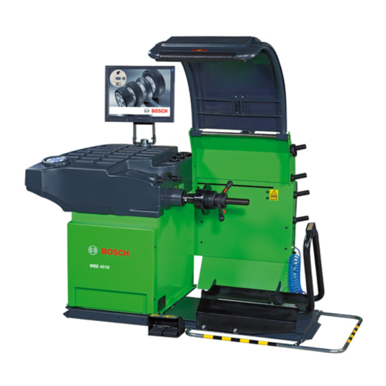
    6 | WBE 4510 - WBE 4515 | Einleitung Einleitung Maschinenbetrieb und Benutzung der Menüs Radwuchtmaschinen mit Bildschirm WBE 4510 - WBE 4515 Die Radwuchtmaschine WBE 4510 basiert auf dem Be- triebssystem Windows CE und ist mit einem 15“ LCD- Bildschirm sowie einer berührungssensitiven Steuerung...
  • Seite 7: Betriebsstörungen Und Fehlercodes

    Betriebsstörungen und Fehlercodes | WBE 4510 - WBE 4515 | 7 Betriebsstörungen und Fehlercodes Während des Betriebs der Radauswuchtmaschine können verschiedene Ursachen für Betriebsstörungen auftreten, die nach ihrer Erfassung durch den Mikroprozessor auf dem Display mit einer Fehlermeldung, gefolgt von einer Nummer zur Erklärung der Bedeutung, angezeigt werden.
  • Seite 8: Betriebsstörungen

    8 | WBE 4510 - WBE 4515 | Betriebsstörungen und Fehlercodes Fehlercode Betriebsstörungen Ursachen und mögliche Abhilfemaßnahmen Err 5 Die Messsensoren wurden nicht Die elektrischen Anschlüsse der Messsenso- angeschlossen. ren überprüfen (Kap. 6.1 und Kap.6.4.1). Err 6 Die Radschutzabdeckung wurde nicht Sicherstellen, dass die Zeit für automatische Absen-...
  • Seite 9 Betriebsstörungen und Fehlercodes | WBE 4510 - WBE 4515 | 9 Fehlercode Betriebsstörungen Ursachen und mögliche Abhilfemaßnahmen Err 26 Fehler bei der Symmetriemessung. Die Messung wiederholen. Falls der Fehler weiter besteht, sicher- stellen, dass das Rad keine zu starken Unregelmäßigkeiten aufweist, um ge- messen werden zu können.
  • Seite 10: Einstellungen Für Den Betrieb

    10 | WBE 4510 - WBE 4515 | Einstellungen für den Betrieb Einstellungen für den Be- Beschreibung trieb Auswahl des zu verwendenden Ge- wichts: Gramm oder Unzen. Auf der Hauptseite die Funktion SETUP auswählen, Auswahl des Visualisierungstyps anschließend das Konfigurationsmenü auswählen. Um der Unwucht: tatsächlicher...
  • Seite 11 Einstellungen für den Betrieb | WBE 4510 - WBE 4515 | 11 Bei der Kalibrierung des Flansches wird der Unwucht- 3. unter Berücksichtung der Anleitungen auf dem wert der Maschinengruppe Welle - Radzentrierkegel ge- Bildschirm einen Messlauf mit dem Rad durchführen, speichert.
  • Seite 12: Eigendiagnose-Menü Und Reparaturprozeduren

    12 | WBE 4510 - WBE 4515 | Einstellungen für den Betrieb Während des letzten Abschnitts der Kalibrierung wird normalen Zugriff als Maschinenverwender nur Funk- auch die Laservorrichtung kalibriert. tionsbeschreibungen und statistische Informationen bereitstellt. Kalibrierung der Laser-Achse Diese Kalibrierung findet derzeit nur werkseitig wäh- Nachdem das Passwort korrekt eingegeben wurde, kön-...
  • Seite 13: Auswuchtsystem

    Einstellungen für den Betrieb | WBE 4510 - WBE 4515 | 13 4.5.2 Auswuchtsystem Die für die Messung der Unwucht verwendete Vorrich- tung verwendet ein mechanisches System, das auf ei- nem zweiarmigen Hebel basiert. Die im unteren Bereich der Welle an den zwei Enden der Welle positionierten...
  • Seite 14: In0 - Signal Des Äußeren Messsensors

    14 | WBE 4510 - WBE 4515 | Einstellungen für den Betrieb Wert des einen Signals ist mit dem tiefsten Wert des 4.5.5 IN0 – Signal des äußeren Messsensors. anderen Signals und umgekehrt ausgerichtet. Ein piezoelektrischer Sensor erfasst die Veränderung einer Krafteinwirkung von außen.
  • Seite 15: Encoder

    Einstellungen für den Betrieb | WBE 4510 - WBE 4515 | 15 4. die unter dem Messsensor positionierte Spezial- Betriebsstörung Korrektur schraube (Nr. 8) mit einem 17 mm-Schlüssel voll- Die Maschine er- Sicherstellen, dass die Scheibe ständig aufschrauben; reicht die 200 nicht mit Staub verschmutzt ist.
  • Seite 16: In2, In3 Und In4

    16 | WBE 4510 - WBE 4515 | Einstellungen für den Betrieb 4.5.9 IN2, IN3 und IN4 Nachdem der Potentiometer ausgetauscht wurde oder Bei dem verwendeten Potentiometer handelt es sich um nachdem festgestellt wurde, dass die Feststellschrau- einen Drehgeber mit Mehrfachumdrehung, dessen Wel- be sich gelockert hat, müssen vor der Kalibrierung die...
  • Seite 17: Digitale Eingänge

    Einstellungen für den Betrieb | WBE 4510 - WBE 4515 | 17 8. die ordnungsgemäße Betriebsweise während des 4.5.10 Digitale Eingänge: Verstellwegs des Potentiometers prüfen; 9. die Maschine wieder schließen; 10. die Prozedur für die Kalibrierung der Messarme fortsetzen (siehe Kalibrierungsmenü).
  • Seite 18 18 | WBE 4510 - WBE 4515 | Einstellungen für den Betrieb Flanschpedal richtung nicht vollständig, muss der Betriebsdruck der Durch Betätigung des Flanschpedals, bzw. der entspre- Druckluftversorgung überprüft werden; sicherstellen, chenden Taste auf der Hubvorrichtung kann die korrek- dass die Auslassöffnungen vollständig geöffnet sind te Betriebsweise des Mikroschalters überprüft werden:...
  • Seite 19: Laser

    Einstellungen für den Betrieb | WBE 4510 - WBE 4515 | 19 HINWEISE FÜR DIE WARTUNG: HINWEISE FÜR DIE WARTUNG: Sollte ein Reparatureingriff am Laser-Aggregat erforder- 1. Flussregler entnehmen. lich sein, ist wie folgt vorzugehen: 2. Druckluftschalauch, der den vordere zylinderkopf mit...
  • Seite 20: Kartenkonfiguration

    20 | WBE 4510 - WBE 4515 | Prozedur für Softwareaktualisierung Kartenkonfiguration Die Karte wird während der Installation konfiguriert, indem zur Eingabe eines Aktivierungscodes aufgefor- dert wird, mit dem die wichtigsten Merkmale festgelegt werden. HINWEISE FÜR DIE WARTUNG Jedes Mal, wenn eine neue Karte installiert oder manu-...
  • Seite 21: Drucker Für Auswuchtmaschine

    Drucker für Auswuchtmaschine | WBE 4510 - WBE 4515 | 21 2. den gesamten Install-Ordner auf dem USB-Stick speichern; 3. den USB-Stick an die Auswuchtmaschine anschlie- ßen; 4. die Maschine einschalten; 5. warten, bis die Aktualisierung vollständig geladen wurde; 6. die Kalibrierung der Maschine wiederholen.
  • Seite 22: Empfohlene Ersatzteile Und Werkzeuge

    22 | WBE 4510 - WBE 4515 | Empfohlene Ersatzteile und Werkzeuge Besteht das Problem weiter, muss der Kunden- dienst kontaktiert werden. Bei Papierstau die Taste 3 des Druckers drücken. Wenn die Kontrollleuchten der Druckerpatronen eingeschaltet bleiben, müssen die Druckerpatronen gewechselt werden.
  • Seite 23: Elektrische Anlage

    Elektrische Anlage | WBE 4510 - WBE 4515 | 23 Elektrische Anlage Robert Bosch GmbH 1 695 655 167 2014-01-13...
  • Seite 24 In the documentation 1.1.2 Symbols in this documentation On the product WBE 4510 - WBE 4515 Introduction Video wheel balancers WBE 4510 - WBE 4515 26 Using instructions and navigation menu Problems and error codes Settings Operator settings Weight setting...
  • Seite 25: Symbols Used

    DANGER Immediate Death severe injury Important – warns of a potentially hazardous situati- danger pending on in which the WBE 4510 - WBE 4515, the test sam- WAR- Possible Death severe impending injury NING danger ple or other object in the vicinity could be damaged.
  • Seite 26: Introduction

    Video wheel balancers WBE 4510 - WBE 4515 WBE 4510 is based on the Win CE operating system, is provided with a 15'' LCD monitor and touch controls. To the normal functions of dynamic and static balan- cing, and the different ALU programs and weight sepa-...
  • Seite 27: Problems And Error Codes

    Problems and error codes | WBE 4510 - WBE 4515 | 27 Problems and error codes During the working of the balancing machine, there can be several problems If the microprocessor detects them, they appear on the display through the notice „Er“ followed by a number which stands for the meaning.
  • Seite 28 28 | WBE 4510 - WBE 4515 | Problems and error codes Error code Problems Causes and possible solutions Err 6 Breaking of the carter micro switch. Substitute or reposition the electormagnet- ic micro switch. (Chapter 6.5). Err 7 The gap of phases of the two Verify that the weight for each calibra- pick-ups is too wide.
  • Seite 29 Problems and error codes | WBE 4510 - WBE 4515 | 29 Error code Problems Causes and possible solutions Err 28 Restore of the motor control alarm. Auto-reset message; wait until the machine re- Reset of the inverter assembly .
  • Seite 30: Settings

    30 | WBE 4510 - WBE 4515 | Settings Settings Machine setting From the start page select SETUP, then select the set- ting menu; use the DOWN and RIGHT ARROW keys to move in the menu and use OK key to confirm.
  • Seite 31: Self-Diagnosis Menu And Mending Procedures

    Settings | WBE 4510 - WBE 4515 | 31 Press the CALIBRATION button, then in sequence the 13. keeping the wheel in this position, press the OK keys ARROW RIGHT - RIGHT - RIGHT - UP to enter the key to confirm the position.
  • Seite 32 32 | WBE 4510 - WBE 4515 | Settings Now the programme requests a password: Press ARROW - UP- OK - RIGHT (service diagnostic password). Press ARROW DOWN - ARROW DOWN - ARROW UP (user diagnosis password). Fig. 8: Menu N° 3:...
  • Seite 33: Balancing System

    Settings | WBE 4510 - WBE 4515 | 33 Fig. 11: Menu N° 6: output 4.5.2 Balancing system To measure the unbalance of the wheel, we use a me- chanical system based on a 1° degree lever. The piezoe- lectric sensors which are in the lower part of the shaft, at its sides, detect vibrations by converting the strength Fig.
  • Seite 34: In1 - Internal Pick-Up Signal

    34 | WBE 4510 - WBE 4515 | Settings 16 17 4.5.6 IN1 - Internal pick-up signal Now the sensor is mounted in the other position. when checking the machine verify that: the rest value is at the half of the range scale;...
  • Seite 35: In2 And In4

    Settings | WBE 4510 - WBE 4515 | 35 NOTES FOR THE ASSISTANCE: Diagnosis of the IN4 Potentiometer of the distance In case of incorrect communication between inverter Defect Correction and CPU, the CPU itself provides to make a reset of the...
  • Seite 36: Digital Inputs

    36 | WBE 4510 - WBE 4515 | Settings How to position the potentiometer of the diameter: NOTES FOR THE ASSISTANCE 1. Remove only the carter without disconnecting the These are the instructions to follow if you want to re- board;...
  • Seite 37 Settings | WBE 4510 - WBE 4515 | 37 Pressing the flange pedal or the keypad lifter button it Selecting with the arrow keys “wheel up/down” and is possible to control the correct functioning of the mi- pressing OK you can control the functionality of the croswitch: if the word “ON”...
  • Seite 38: Laser

    38 | WBE 4510 - WBE 4515 | Settings 5. TURN THE ADJUSTING SCREW UNTIL THE WHEEL COVER IS RAISED TO 5.5" +/- 0.5" ON FIRST CONNEC- TION OF COMPRESSED AIR. 4.5.11 Laser The laser assembly makes the additional measurements of the wheel (eccentricity and drift) and in the standard program (peg weights) it measures the rim width.
  • Seite 39: Software Update Procedure

    Software update procedure | WBE 4510 - WBE 4515 | 39 Software update procedure Following the instructions given above it is possible to reset the inserted machine code: The new generation of bards introduced by Sicam functions in Windows CE environment; this allows our...
  • Seite 40: Printer For Balancers

    40 | WBE 4510 - WBE 4515 | Printer for balancers Printer for balancers 6. Power up the machine and eventually the printer (if not given together with the machine). 7. Push the Start button and turn on the printer.
  • Seite 41: Spare Parts And Suggested Tools

    Spare parts and suggested tools | WBE 4510 - WBE 4515 | 41 Spare parts and suggested tools Tools which are essential for a correct maintenance: A set of Allen wrenches A screwdriver set (slotted and Phillips) A hex key set...
  • Seite 42: Electrical System

    42 | WBE 4510 - WBE 4515 | Electrical system Electrical system 1 695 655 167 2014-01-13 Robert Bosch GmbH...
  • Seite 43 Electrical system | WBE 4510 - WBE 4515 | 43 Robert Bosch GmbH 1 695 655 167 2014-01-13...
  • Seite 44 44 | WBE 4510 - WBE 4515 | Índice Símbolos empleados En la documentación 1.1.2 Símbolos en esta documentación En el producto WBE 4510 - WBE 4515 Introducción Balanceadores video WBE 4510 - WBE 4515 Modo de uso y navegación menú...
  • Seite 45: Símbolos Empleados

    PELIGRO Peligro in- Muerte o lesio- WBE 4510 - WBE 4515, la probeta o algún objeto del mediato nes físicas graves entorno. ADVER- Peligro amena- Muerte o lesio-...
  • Seite 46: Introducción

    Modo de uso y navegación menú Balanceadores video WBE 4510 - WBE 4515 La WBE 4510 está basada en el sistema operativo Win CE, y está dotada de un monitor LCD de 15“y de un sistema de control táctil. Además de las funciones nor- males de balanceado dinámico y estático, a los distin-...
  • Seite 47: Averias Y Códigos De Errores

    Averias y códigos de errores | WBE 4510 - WBE 4515 | 47 Averias y códigos de errores Durante el funcionamiento de la máquina puede haber diversas averias que, si son identificadas por el micropro- cesador, aparecen en la pantalla con la palabra “Er” seguida de un número que indica el significado.
  • Seite 48 48 | WBE 4510 - WBE 4515 | Averias y códigos de errores Código error Malfuncionamiento Causas y posibles soluciones Err 6 El carter de protección no se ha bajado. Controlar que el tiempo de cierre automáti- co del carter no sea demasiado alto.
  • Seite 49 Averias y códigos de errores | WBE 4510 - WBE 4515 | 49 Código error Malfuncionamiento Causas y posibles soluciones Err 27 Error medida ancho Repetir la medición. Controlar que el láser realice su curso antes del lanzamiento. Controlar que la rueda no salga del campo de medición.
  • Seite 50: Configuración Para El Uso

    50 | WBE 4510 - WBE 4515 | Configuración para el uso Configuración para el uso Configuración máquina Seleccionar SET UP de la página inicial ,o sea el menú de configuración, utilizar los botones FLECHA ABAJO y DERECHA para moverse en los menúes y confirmar Fig.
  • Seite 51 Configuración para el uso | WBE 4510 - WBE 4515 | 51 Pulsar el botón TARA, después los botones FLECHA DE- 9. al final del lanzamiento, siguiendo las instruccio- RECHA – DERECHA – DERECHA – ARRIBA sucesivamen- nes del vídeo es necesario girar manualmente la te para entrar en el menú...
  • Seite 52: Menú De Auto-Diagnosis Y Procedimiento De Repa- Ración

    52 | WBE 4510 - WBE 4515 | Configuración para el uso - Versión software de la máquina Menú de auto-diagnosis y procedimi- - Parámetros de tara ento de reparación - Efectuar un lanzamiento de verificación - Estado de la máquina En todas las versiones de equilibradoras Sicam está...
  • Seite 53: Sistema De Equilibrado

    Configuración para el uso | WBE 4510 - WBE 4515 | 53 4.5.4 Diferencia de fase En general, con el término fase se indica un particular instante durante el desarrollo de un fenómeno perió- dico (en este caso la señal eléctrica generada por los pick-up durante el lanzamiento de la rueda).
  • Seite 54: In0 - Señal Del Pick-Up Externo

    54 | WBE 4510 - WBE 4515 | Configuración para el uso NOTAS PARA LA ASISTENCIA: 3. aflojar los dos tornillos de fijación (n. 10) colocados Si, comprobando la relación entre los pick-up y la debajo del grupo de medida;...
  • Seite 55: Motor E Inverter

    Configuración para el uso | WBE 4510 - WBE 4515 | 55 4.5.8 Motor e Inverter Diagnosis Potenciómetro de la distancia IN2 Actualmente no se ha creado una pagina específica Defecto Corrección para el control del motor, por lo tanto se debe proceder...
  • Seite 56: Ingresos Digitales

    56 | WBE 4510 - WBE 4515 | Configuración para el uso 5. desbloquear el tornillo de la abrazadera “A”; 5. manteniendo el calibre en reposo, girar el potenció- 6. manteniendo el calibre en reposo, girar el potenció- metro “B”hasta el valor de 1000 ± 50;...
  • Seite 57 Configuración para el uso | WBE 4510 - WBE 4515 | 57 con el mensaje de error Numero 6 (el carter no ha sido setup que esté activo o proceder con la sustitución del bajado) el malfuncionamiento del micro mismo.
  • Seite 58: Láser

    58 | WBE 4510 - WBE 4515 | Configuración para el uso NOTAS PARA LA ASISTENCIA: 6. Al final del lanzamiento volver a la sección de los programas para controlar si la máquina ha ejecutado 1. QUITAR EL REGULADOR DE FLUJO.
  • Seite 59: Comfiguración De La Tarjeta

    Configuración para el uso | WBE 4510 - WBE 4515 | 59 Comfiguración de la tarjeta Reset Código Máquina La tarjeta viene configurada en fase de instalación pidi- Es posible anular el código introducido siguiendo las endo un código de activación que determina los princi- instrucciones descritas: pales detalles.
  • Seite 60: Procedimiento De Actualización Del Software

    60 | WBE 4510 - WBE 4515 | Procedimiento de actualización del software Procedimiento de actuali- Impresora para balancea- zación del software dora La nueva generación de tarjetas introducidas por Si- cam funciona en ambiente Windows CE; esto permite a nuestro departamento de investigación y desarrollo actualizar constantemente las máquinas, de forma que...
  • Seite 61: Recambios E Instrumentos Aconsejados

    Recambios e instrumentos aconsejados | WBE 4510 - WBE 4515 | 61 Recambios e instrumentos aconsejados Instrumentos indispensables para una correcta asisten- cia: Set de llaves Allen (hexagonales) Set destornilladores (de estrella y corte) Set llaves hexagonales Teclado USB Llave USB para actualizaciones 1.
  • Seite 62: Instalación Eléctrica

    62 | WBE 4510 - WBE 4515 | Instalación eléctrica Instalación eléctrica 1 695 655 167 2014-01-13 Robert Bosch GmbH...
  • Seite 63 Instalación eléctrica | WBE 4510 - WBE 4515 | 63 Robert Bosch GmbH 1 695 655 167 2014-01-13...
  • Seite 64 64 | WBE 4510 - WBE 4515 | Indice Simboli utilizzati Nella documentazione 1.1.2 Simboli nella presente documentazione Sul prodotto Introduzione Equilibratrici video WBE 4510 - WBE 4515 Modo d’uso e navigazione menù Malfunzionamenti e codici di errore Configurazione d’uso...
  • Seite 65: Simboli Utilizzati

    Simboli utilizzati | WBE 4510 - WBE 4515 | 65 Simboli utilizzati Sul prodotto Nella documentazione ! Rispettare tutti i simboli di avvertimento sui prodotti 1.1.1 Indicazioni di avvertimento – e mantenere le relative etichette integralmente in struttura e significato condizioni di perfetta leggibilità!
  • Seite 66: Introduzione

    WBE 4510 - WBE 4515 centre; però collegando una tastiera da PC di tipo USB La WBE 4510 è basata sul sistema operativo Win CE, è con le frecce direzione e il tasto invio (OK) si hanno le dotata di monitor LCD da 15”e di un sistema di control- stesse funzioni.
  • Seite 67: Malfunzionamenti E Codici Di Errore

    Malfunzionamenti e codici di errore | WBE 4510 - WBE 4515 | 67 Malfunzionamenti e codici di errore Durante il funzionamento della macchina ci possono essere diverse cause di malfunzionamento che, se rilevate dal microprocessore, vengono indicate sul display con un messaggio d’errore seguito da un numero che ne indica il significato.
  • Seite 68 68 | WBE 4510 - WBE 4515 | Malfunzionamenti e codici di errore Codice errore Malfunzionamenti Cause e possibili rimedi Err 7 La differenza di fase fra i 2 pick-up è troppo Verificare che il peso per taratura sia stato applicato corretta- grande.
  • Seite 69 Malfunzionamenti e codici di errore | WBE 4510 - WBE 4515 | 69 Codice errore Malfunzionamenti Cause e possibili rimedi Err 28 Ripristino allarme controllo motore. Messaggio di auto-reset; attendere l’avvenuto reset e proceder Reset del gruppo inverter. con una misurazione.
  • Seite 70: Configurazione D'uso

    70 | WBE 4510 - WBE 4515 | Configurazione d’uso Configurazione d’uso Configurazione macchina Dalla pagina iniziale selezionare SETUP, quindi selezio- nare il menu di configurazione; utilizzare i tasti FREC- CIA GIU e DESTRA per muoversi nei menu e confermare Fig.
  • Seite 71 Configurazione d’uso | WBE 4510 - WBE 4515 | 71 Premere il tasto TARATURA, poi in sequenza i tasti 10. tenendo la ruota in questa posizione, premere il FRECCIA DESTRA - DESTRA - DESTRA - SU per entrare tasto OK per confermare la posizione.
  • Seite 72: Menù Di Auto-Diagnosi E Procedure Di Riparazione

    72 | WBE 4510 - WBE 4515 | Configurazione d’uso - Effettuare un lancio di verifica Menù di auto-diagnosi e procedure di - Stato della macchina riparazione Su tutte le versioni di bilanciatrici Sicam è presente un menù di auto-diagnosi che può essere utilizzato in fase di assistenza per controllare in modo approfondito l’apparecchiatura.
  • Seite 73: Sistema Di Bilanciatura

    Configurazione d’uso | WBE 4510 - WBE 4515 | 73 4.5.4 Differenza di fase In generale, con il termine fase si indica un particolare istante durante lo svolgersi di un fenomeno periodico (in questo caso il segnale elettrico generato dai pick-up durante il lancio della ruota).
  • Seite 74: In0 - Segnale Del Pick-Up Esterno

    74 | WBE 4510 - WBE 4515 | Configurazione d’uso stituzione pick-up). Se dopo la sostituzione di entrambi 4. con una chive da 17 mm svitare completamente la il problema persiste può essere causato da un disturbo vite speciale posta sotto il pick-up (n° 8);...
  • Seite 75: Motore E Inverter

    Configurazione d’uso | WBE 4510 - WBE 4515 | 75 voce “enc”. Verificare quale possa essere la causa del 4.5.9 IN2 e IN4 difetto per correggere nel modo adeguato il problema. Il potenziometro utilizzato è di tipo multigiro, in cui l'albero deve compiere più...
  • Seite 76 76 | WBE 4510 - WBE 4515 | Configurazione d’uso Procedura posizionamento potenziometro distanza Aludata: 1. Rimuovere il solo carter portatesi senza scollegare la scheda; Procedura posizionamento potenziometro larghezza: 2. avviare l'equilibratrice; 1. Rimuovere il solo carter portatesi senza scollegare la 3.
  • Seite 77: Ingressi Digitali

    Configurazione d’uso | WBE 4510 - WBE 4515 | 77 4.5.10 Ingressi digitali: microinterruttore: se non dovesse comparire la scritta "ON" con il multimetro controllare il microinterruttore e il cavo. Clamp button Premendo il pulsante tastierino sollevatore si può con- trollare il corretto funzionamento del microinterruttore: se non dovesse comparire la scritta "ON"...
  • Seite 78: Laser

    78 | WBE 4510 - WBE 4515 | Configurazione d’uso Selezionando tramite le frecce “wheel up/down” e 4.5.11 Laser premendo OK si controlla la funzionalità della morsa Il gruppo laser esegue le misure addizionali della ruota sollevatore: se non dovesse funzionare procedere con la (eccentricità...
  • Seite 79: Sostituzione Scheda

    Configurazione d’uso | WBE 4510 - WBE 4515 | 79 Sostituzione scheda Per inserire il codice premere i tasti FRECCIA per in- crementare le cifre e il tasto F2 per spostarsi al campo NOTE PER L’ASSISTENZA successivo. Quando si presenta la necessità di sostituire la scheda (cod.
  • Seite 80: Procedura Di Aggiornamento Software

    80 | WBE 4510 - WBE 4515 | Procedura di aggiornamento software Procedura di aggiornamen- Stampante per equilibratri- to software La nuova generazione di schede introdotta da Sicam lavora in ambiente Windows CE; questo permette al nostro dipartimento di ricerca e sviluppo di aggiornare...
  • Seite 81: Ricambi E Strumenti Consigliati

    Stampante per equilibratrice | WBE 4510 - WBE 4515 | 81 Ricambi e strumenti consi- Avvertimento: gliati Per accendere o spegnere la stampante, utilizzare sem- pre il pulsante di accensione. Strumenti indispensabili per una corretta assistenza: Risoluzione dei problemi Set di chiavi a brugola Completata l’installazione della stampante verificare...
  • Seite 82: Impianto Elettrico

    82 | WBE 4510 - WBE 4515 | Impianto elettrico Impianto elettrico 1 695 655 167 2014-01-13 Robert Bosch GmbH...
  • Seite 83 Impianto elettrico | WBE 4510 - WBE 4515 | 83 Robert Bosch GmbH 1 695 655 167 2014-01-13...
  • Seite 84 Robert Bosch GmbH Diagnostics Franz-Oechsle-Straße 4 73207 Plochingen DEUTSCHLAND www.bosch.com bosch.prueftechnik@bosch.com Printed in Germany / Imprimé en Allemagne 1 695 655 167 | 2014-01-13...

Diese Anleitung auch für:

Wbe 4515

Inhaltsverzeichnis