Inhaltsverzeichnis
Werbung
Verfügbare Sprachen
Verfügbare Sprachen
Quicklinks
Italiano
REGOLATORE
English
CONTROLLER
Deutsch
REGLER
Français
RÉGULATEUR
Español
REGULADOR
Portuguese
CONTROLADOR
1200/1300
Software 2.0x
cod. 81801A / Edit. 02 - 06/04
- Manuale d'uso
- User's Manual
- Bedienungsanleitung
- Manuel d'Utilisation
- Manual de Uso
- Manual do Usuário
2
42
82
121
161
201
Werbung
Kapitel
Inhaltsverzeichnis
Fehlerbehebung

Verwandte Anleitungen für gefran 1200


Inhaltszusammenfassung für gefran 1200
- Seite 1 1200/1300 Software 2.0x cod. 81801A / Edit. 02 - 06/04 Italiano REGOLATORE - Manuale d’uso English CONTROLLER - User’s Manual Deutsch REGLER - Bedienungsanleitung Français RÉGULATEUR - Manuel d’Utilisation Español REGULADOR - Manual de Uso Portuguese CONTROLADOR - Manual do Usuário...
-
Seite 2: Inhaltsverzeichnis
1200 / 1300 TERMOREGOLATORE ISTRUZIONI PER L’USO ED AVVERTENZE Versione software 2.0x codice 81801A / Edizione 02 - 06/04 INDICE GENERALE pagina pagina Simbologia Grafica Adottata Note Applicative Istruzioni Preliminari Funzionamento Allarme HB Descrizione Generale Funzionamento Tipo HOLD Regolatore in Versione Base... -
Seite 3: Simbologia Grafica Adottata
1 • ISTRUZIONI PRELIMINARI Questa sezione riporta le informazioni e le I termoregolatori serie 1200/1300 sono realizzati su una avvertenze di natura generale che si racco- piattaforma hardware e software estremamente versatile manda di leggere prima di procedere all’instal- che consente di scegliere,tramite opzioni, la composizio- lazione, configurazione e uso del regolatore. -
Seite 4: Interfaccia Operatore
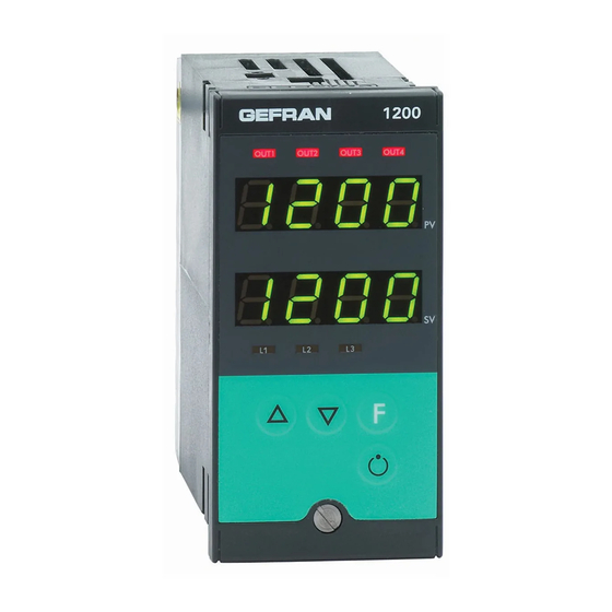
4 pulsanti utilizzabili per le operazioni di configurazione • Tensione di alimentazione / selezione/regolazione manuale Esempio: 1200 – RT – RR – 00 – 0 – 1 • 2 display a quattro cifre di colore verde (Variabile di Regolatore Modello 1200 Processo e Variabile di Set point) Uscita 1 - Relè;... -
Seite 5: Installazione E Collegamento
, macchine o materiali, è indispen- 1200/1300 nel pannello di controllo della mac- sabile il suo abbinamento con apparati ausiliari di china o sistema ospite e per il corretto collega- allarme. -
Seite 6: Alimentazione Dello Strumento
- la resistenza Ohmica deve essere <6Ω; • Nel caso in cui la tensione di rete sia fortemente GEFRAN S.p.A. non si ritiene in alcun caso variabile, utilizzare uno stabilizzatore di tensione. responsabile per eventuali danni a persone •... -
Seite 7: Dimensioni Di Ingombro E Di Foratura
Esempio: 1200/1300 – xx – xx – xx – x – 1 = 100..240Vac/dc 1200/1300 – xx – xx – xx – x – 0 = 11..27Vac/dc... -
Seite 8: Collegamenti Elettrici
Collegamenti Elettrici 1200 Uscite Out3 - Out4 Uscite Out1 - Out2 Ingressi Digitali Ingresso TA Linea seriale Ingressi Effettuare le connessioni utilizzando sempre tipi di cavo adeguati ai limiti di tensione e corrente indicati nella Sezione 5 – Caratteristiche Tecniche. - Seite 9 Ingressi Ingresso Lineare (V) Ingresso PTC/NTC/Pt100/JPT100 Jumper S2 chiuso Ingresso lineare in scheda CPU tensione continua (vedi Cap. 6 - 60 mV, 1V (Ri > 1MΩ) Manutenzione) 5V, 10V (Ri > 10KΩ) Usare fili di sezio- ne adeguata (min. 1mm collegamento 2 fili collegamento 3 fili Uscite Out1, Out 2...
-
Seite 10: Esempio Di Collegamento Con Ingresso
Linea Seriale Modbus 2 fili (Standard) Modbus 4 fili / Cencal Linea seriale isolata RS485 Linea seriale isolata RS485 Per configurazione Modbus 4 fili/Cencal. (data -) (data +) Esempio di Collegamento con Ingresso TC Riscaldamento elettrico con gruppo statico e raffreddamento ad acqua con elettrovalvola OUT1 relé... -
Seite 11: Operatività
Questa sezione illustra le funzioni e le modalità di utilizzo dei display, degli indicatori luminosi e dei pul- santi che costituiscono l’interfaccia operatore dei regolatori 1200/1300. Rappresenta quindi un requisito essenziale per poter eseguire correttamente la programmazione e la configurazione dei regolatori. -
Seite 12: Note Operative Generali
Note operative generali Accensione e Funzionamento del Regolatore Autodiagnostica • Subito dopo l’accensione il regolatore esegue un test di autodiagnostica. Durante il test, tutti i segmenti del display e i 7 indicatori luminosi lampeggiano. • Se l’autodiagnostica non rileva errori il regolatore entra nello stato di normale funzionamento (Livello 1) •... -
Seite 13: Navigazione Nei Menu Del Regolatore
Navigazione nei Menù del Regolatore Tenere premuto per scorrere i menu in successione e rilasciarlo quando compare il menu desiderato. Premere per accedere ai parametri del menu selezionato. Tenendo premuti si ritorna immediatamente al livello 1. Visualizzazione livello 1 Menu Visualizzazione 39. -
Seite 14: Configurazione E Programmazione
L’accesso a tutti i menu di configurazione / programmazione e per accedere ai menu successivi. a tutti i parametri disponibili per i Regolatori 1200/1300 in confi- gurazione Estesa, permette di configurare il Regolatore nei Codice di Protezione: P P R R O O minimi dettagli, per soddisfare qualsiasi esigenza applicativa. -
Seite 15: Configurazione/Programmazione Easy
Configurazione/Programmazione EASY Standard per strumento con 2 uscite: OUT1 = AL1 / OUT2 = MAIN HEAT Nella configurazione EASY, il flusso di navigazione generale riportato al termine della Sezione 3 – Operatività risulta notevolmente semplificato, come illustrato nella figura seguente. Visualizzazione livello 1 Menu 39. - Seite 16 ( ( F F G G -Easy- Configurazione Quarto menù da configurare Questo menù permette di configurare i parametri di regolazione in versione Easy. S.tun Autotuning Selftuning Softstart continuo Abilitazione Self Tuning, Auto Tuning, S. v Soft Start (**) S.tun Autotuning Selftuning Softstart...
- Seite 17 I I N N P P -Easy- Impostazione Ingressi Terzo menù da configurare T T Y Y P P Tipo sonda Senza punto Con punto Dec. Dec. DP. S = 0 DP. S = 1 Sensore: TC J °C 0/1000 0.0/999.9 TC J °F 32/1832...
- Seite 18 -Easy- Impostazione Uscite Secondo menù da configurare Questo menù permette di configurare il tipo di Allarme 1 e il tempo di ciclo dell’Uscita 2. A A 1 1 . . T T Diretto (di massima) Normale Inverso Assoluto/Relativo Simmetrico (di minima) al Setpoint attivo (finestra) AI.
- Seite 19 P P R R O O -Easy- Codice di Protezione Questo menù permette di abilitare o disabilitare la visualizzazione e/o modifica di determinati parametri e di acce- dere alla configurazione estesa. P P R R O O Visualizzazione Modifica SP, allarmi SP, allarmi SP, allarmi sommando al valore indicato in tabella le seguenti cifre...
-
Seite 20: Configurazione/Programmazione Estesa
CONFIGURAZIONE / PROGRAMMAZIONE ESTESA (Cenni) Questa sezione contiene alcuni cenni sulle principali funzioni offerte dalla Configurazione Estesa. Configurazione Hardware K K R R D D Questo menù permette di configurare i parametri hardware del Regolatore. Di seguito come settare alcune delle principali funzioni offerte [ [ T T R R Tipo di Controllo P caldo... - Seite 21 ( ( F F G G Configurazione Quarto menù da configurare Questo menù permette di configurare i vari parametri di regolazione. S.tun Autotuning Selftuning Softstart continuo Abilitazione Self Tuning, Auto Tuning, S. v Soft Start (**) Banda proporzionale di riscaldamento h.
- Seite 22 [ g f g ] c. L Limite MIN potenza di raffreddamento 0. 0 (non disponibile per doppia azione caldo/freddo) [0.0 ... 100.0] % Reset Manuale S r t [-999 ... +999] punti scala Potenza di Reset P. S 0. 0 [-100.0 ...
- Seite 23 Codice Identificazione Strumento [0 ... 247] Protocollo Interfaccia Seriale S S R R . . P P Protocollo Seriale [0 ... 1] CENCAL Gefran MODBUS RTU Selezione Baudrate B B A A V V Baudrate 1200 [0 ... 4]...
- Seite 24 I I n n P P Impostazione Ingressi Terzo menù da configurare Questo menù permette di configurare i parametri per i segnali di ingresso del Regolatore. S S P P . . R R Tipo Set Remoto, Assoluto / Relativo Digitale (da linea seriale) Assoluto Definizione tipo Set Remoto Digitale (da linea seriale) Relativo set SP o SP1 o SP2...
- Seite 25 I I n n P P DP.S Formato dP. S Posizione Punto Decimale per Scala xxxx Ingresso xxx.x xx.xx (*) x.xxx (*) (*) NON disponibile per sonde TC, RTD, PTC, NTC Lo. S Limite MIN Scala Ingresso Principale Valore Min..Max associato all’ingresso selezionato con il parametro TYP Ki .
- Seite 26 0 0 V V T T Impostazione Uscite Secondo menù da configurare Questo menù permette di configurare i parametri delle uscite del Regolatore. A A 1 1 . . R R i. A Selezione grandezze di riferimento A A 2 2 . . R R Allarme 1 A A 3 3 .
- Seite 27 R R L L . . 1 1 ; R R L L . . 2 2 0 0 V V T T R R L L . . 3 3 ; R R L L . . 4 4 Funzione HEAT (uscita di controllo riscaldamento) COOL (uscita di controllo raffreddamento)
- Seite 28 P P R R O O Codice di Protezione Questo menù permette di abilitare/disabilitare la visualizzazione e/o modifica di determinati parametri e di accede- re alla configurazione Easy. (Per l’accesso a questo menù fare riferimento alla sezione “Navigazione nei menù del regolatore”) Visualizzazione Modifica...
- Seite 29 K K R R D D A A L L . . N N Allarme 1 Allarme 2 Allarme 3 disabilitato disabilitato disabilitato abilitato disabilitato disabilitato Selezione Numero di Allarmi Abilitati disabilitato abilitato disabilitato abilitato abilitato disabilitato disabilitato disabilitato abilitato abilitato disabilitato abilitato...
- Seite 30 L L ' ' N N Linearizzazione Ingresso Questo menù permette di eseguire la linearizzazione custom per l’ingresso principale. i L n Passo 0 (valore di inizio scala) Limiti di visualizzazione del display: [-1999 ... 9999] ..Il valore del passo “n” corrisponde all’ingresso: mV inizio scala + n* mV mV = (mv fondo scala –...
-
Seite 31: Note Applicative
Note Applicative Funzionamento Allarme HB Questo tipo di allarme è condizionato dall’utilizzo dell’ingresso da trasformatore amperometrico (T.A.). Può segnalare variazioni di assorbimento nel carico discriminando il valore della corrente in ingresso amperometri- co nel campo (0 ... HS.2). Viene abilitato tramite codice di configurazione (AL.n); in questo caso il valore di inter- cettazione dell’allarme è... -
Seite 32: Tecnica Di Tune Manuale
Se il valore del Tempo Integrale è troppo lungo (Azione Integrale debole) è possibile una persistenza della devia- zione tra variabile regolata e valore desiderato. Per avere ulteriori informazioni relative alle azioni di controllo con- tattare GEFRAN. Tecnica di Tune Manuale Impostare il set-point al valore operativo. -
Seite 33: Accensione/Spegnimento Software
Accensione / Spegnimento Software Come spegnere: tramite la combinazione di tasti “ F ” e “ Incrementa ” premuti insieme per 5 secondi è possibile disattivare lo strumento, che si predispone in stato di “ OFF ” assumendo un comportamento simile allo strumento spento, senza togliere l’alimentazione di rete, mantenendo attiva la visualizzazione della variabile di processo, il display SV è... -
Seite 34: Auto-Tuning
Auto-Tuning L'abilitazione della funzione auto-tuning blocca le impostazioni dei parametri PID. Può essere di due tipi: permanente ( continuo) e a singola azione (one shot). * L'Auto-Tunìng permanente si attiva attraverso il parametro Stu (valori 1,3,5); esso continua a valutare le oscillazioni del sistema cercando quanto prima possibile i valori dei parametri PID che riducono l'oscillazione in essere;... -
Seite 35: Caratteristiche Tecniche
5 • CARATTERISTICHE TECNICHE Questa sezione riporta l’elenco dei Dati Tecnici caratteristici del Regolatore 1200/1300. Display 2x4 digit verde, altezza cifre 10 e 7mm Tasti 4 di tipo meccanico (Man/Aut, INC, DEC, F) Accuratezza 0.2% f.s. ±1 digit a temperatura ambiente di 25°C Deriva termica 0,005% f.s. -
Seite 36: Manutenzione
10-11. Verificare che la tensione di alimentazione corrisponda alle specifiche indicate nella sigla di ordinazione: 1200/1300 – xx – xx – xx – x – 1 = 100..240Vac/dc 1200/1300 – xx – xx – xx – x – 0 = 11..27Vac/dc I caratteri visualizzati sul Possibile guasto su uno o più... -
Seite 37: Informazioni Tecnico-Commerciali
IN1 + IN2 (NPN / PNP) Triac (1A) IN1 + IN TA (50mAac) USCITA 3 Nessuna Relé Logica Continua 0...10V (0/4...20mA) Analogica 0/4...20mA (0...10V) USCITA 4 Nessuna Relé Logica Per le informazioni sulla disponibilità dei codici si prega di contattare il Rivenditore Gefran. -
Seite 38: Trasformatore Amperometrico
Lunghezza cavo: 5,50m PTC 7 x 25 5m • Cavo Interfaccia RS232 / TTL per configurazione strumenti GEFRAN N.B.: L’interfaccia RS232 per la configurazione da PC è for- nito unitamente al software di programmazione WINSTRUM. Il collegamento deve essere effettuato con strumento alimen- tato con ingressi e uscite non collegate. -
Seite 39: Appendice
APPENDICE L’appendice riporta l’elenco di tutte le sigle dei parametri che compaiono nei vari menu di configurazio- ne/programmazione con i rispettivi valori di default e significati. La colonna CONF può essere utilizzata per riportare i valori modificati dall’utente rispetto alla configura- zione di default, in base alle esigenze applicative. - Seite 40 Display Default CONF Acronimo Descrizione Menu S S E E R R Instrument Code Identificativo codice strumento SR. P Serial Protocol Protocollo Interfaccia Seriale bAudrate Selezione Baudrate PArity Selezione Parità S. I N S. Input Ingressi Strumento Virtuale S. 0 V S.
- Seite 41 Menu L L iN N - Linearizzazione ingressi S00 – S35 N° Default CONF N° Default CONF N° Default CONF N° Default CONF N° Default CONF S.00 S.08 S.16 S.24 S.32 1000 S.01 S.09 S.17 S.25 0.00 S.02 S.10 S.18 S.26 S.34 0.00...
- Seite 42 1200 / 1300 TEMPERATURE CONTROLLER INSTRUCTIONS FOR USE AND WARNINGS Software Version 2.0x code 81801A / Edition 02 - 06/04 GENERAL INDEX page page Graphic symbol used Application notes Preliminary instructions HB Alarm General description HOLD function Basic version controller...
-
Seite 43: Graphic Symbol Used
General Description • 4 outputs GEFRAN series 1200 / 1300 digital controllers have • 3 inputs (2 of which are auxiliary) been designed for temperature control in any •... -
Seite 44: Operator Interface
• Mains voltage supply • 2 green four-digit displays Example: 1200 – RT – RR – 00 – 0 – 1 (Process Variable and Set point Variable) Model 1200 controller • 4 red LEDs for status indication of same number of Output 1 - Relay;... -
Seite 45: Installation And Connection
2 • INSTALLATION AND CONNECTION This section contains the instructions necessary • if the controller is used in applications with risk of for correct installation of the 1200/1300 damage to persons, machinery or materials, it is controllers into the machine control panel or the... -
Seite 46: Advice For Correct Installation For Emc
Direct Current. - the voltage between neutral and earth must not be >1V - the Ohmic resistance must be <6Ω; GEFRAN S.p.A. declines all responsibility for • If the mains voltage fluctuates strongly, use a voltage any damage to persons or property caused stabilizer. -
Seite 47: Dimensions And Cut-Out
Example: 1200/1300 – xx – xx – xx – x – 1 = 100..240Vac/dc 1200/1300 – xx – xx – xx – x – 0 = 11..27Vac/dc... -
Seite 48: Electrical Connections
Electrical Connections 1200 Outputs Out3 - Out4 Outputs Out1 - Out2 Digital inputs CT Input Serial line Inputs Always make the connections using cable types suitable for the voltage and current limits given in Section 5 - Technical Specifications. If the Controller has faston terminals these must be protected and isolated. - Seite 49 Inputs Linear input (V) PTC/NTC/Pt100/JPT100 input Jumper S2 closed on CPU board Linear input in (see CAP. 6 Direct Current Maintenance) 60 mV, 1V (Ri > 1MΩ) 5V, 10V (Ri > 10KΩ) Use wires of adeguate diameter (min. 1mm 2-wire connection 3-wire connection Outputs Out1, Out 2 User configurable generic outputs...
-
Seite 50: Example Of Connection With Tc Input Electric Heating With Power Solid State Relay And Water Cooling With Solenoid Valve
Serial line Modbus 2 wires (Standard) Modbus 4 wires / Cencal RS485 isolated serial line RS485 isolated serial line For configuration Modbus 4 wires/Cencal. (data -) (data +) Example of connection with TC Input Electric heating with power solid state relay and water cooling with solenoid valve OUT1 relay OUT2 logic... -
Seite 51: Functions
This section illustrates the functions and operating modes of the displays, the indicator lights and the buttons that make up the operator interface of series 1200/1300 controllers. It is therefore an essential requirement for programming and configuring the controllers correctly. -
Seite 52: General Operating Notes
General Operating Notes Switching on and using the Controller Self-diagnostics • Immediately after switching on the controller carries out a self-diagnostic test. During the test, all the display segments and the 7 indicator lights will flash. • If the self-diagnostics procedure does not detect any errors the controller enters the normal working status (Level 1) •... -
Seite 53: Navigating Through The Controller Menu
Navigating through the Controller Menu Keep pressed down to scroll through the menus in sequence and release it when the required menu appears. Press to access the parameters of the selected menu. Keep to return immediately to level 1. Level 1 Display Menu 39. -
Seite 54: Configuration And Programming
Integral heating time [0.0 ... 99.99] % f.s. 4. 0 0 Optimal working operation of the 1200/1300 Controller in the field of application it is intended for depends largely on correct (default value) configuration and programming of the relevant control parameters. - Seite 55 EASY Configuration/Programming Standard for instrument with 2 Outputs: OUT1 = AL1 / OUT2 = MAIN HEAT In the EASY configuration, the general navigation flow shown at the end of Section 3 - Functions is considerably simplified, as illustrated in the following figure. Level 1 display Menu 39.
- Seite 56 ( ( F F G G -Easy- Configuration Fourth menu to set up This menu is used to configurare the control parameters in the Easy mode. S.tun Continuous Selftuning Softstart autotunig Enabling self-tuning, autotuning, S. v softstart (**) S.tun Single action Selftuning Softstart Autotuning...
- Seite 57 I I N N P P -Easy- Inputs Settings Third menu to set up T T Y Y P P Probe type Without dec. With dec. point point DP. S = 0 DP. S = 1 Sensore: TC J °C 0/1000 0.0/999.9 TC J °F...
- Seite 58 -Easy- Outputs Settings Second menu to set up This menu is used to configure the type of Alarm 1 and the Output 2 cycle time. A A 1 1 . . T T Direct (high limit Normal Inverse Absolute/Relative Symmetric (low limit) to active Setpoint (window)
- Seite 59 P P R R O O -Easy- Protection code This menu is used to enable or disable the display and/or editing of certain parameters and to access the exten- ded configuration. P P R R O O Display Modification SP, alarms SP, alarms SP, alarms By adding the following amounts to the values shown...
-
Seite 60: Configuration/Programming
EXTENDED PROGRAMMING CONFIGURATION (Signals) This section contains some signals on the main functions offered from the Extensive Configuration Hardware configuration K K R R D D This menu makes it possible to configure the Controller hardware parameters. Some of the main offered functions [ [ T T R R Control type P heat... - Seite 61 ( ( F F G G Configuration Fourth menu to set up This menu makes it possible to configure various control parameters. S.tun Continuous Selftuning Softstart autotunig Enabling self-tuning, autotuning, S. v softstart (**) Proportional band for heating or hysteresis h.
- Seite 62 [ g f g ] c. L Minimum power limit for cooling (not available for 0. 0 heating/cooling double action [0.0 ... 100.0] % Manual Reset S r t [-999 ... +999] scale points Reset power P. S 0. 0 [-100.0 ...
- Seite 63 Instrument identification code [0 ... 247] Serial interface protocol S S R R . . P P Serial protocol [0 ... 1] CENCAL Gefran MODBUS RTU Select Baudrate B B A A V V Baudrate 1200 [0 ... 4]...
- Seite 64 I I n n P P Input settings third menu to set up This menu makes it possible to configure the parameters for the Controller input signals. S S P P . . R R Type of remote setpoint, Absolute / Relative Digital (from serial line) Absolute Def.
- Seite 65 I I n n P P DP.S Format dP. S Decimal point position for input xxxx scale xxx.x xx.xx (*) x.xxx (*) not available for TC, RTD, PTC, NTC probes Lo. S Minimum limit of main input scale Min... Max value associated with the input selected with the TYP parameter Ki .
- Seite 66 0 0 V V T T Output settings Second menu to set up This menu makes it possible to configure the parameters of the Controller outputs. A A 1 1 . . R R i. A Select reference signal for alarm A A 2 2 .
- Seite 67 R R L L . . 1 1 ; R R L L . . 2 2 0 0 V V T T R R L L . . 3 3 ; R R L L . . 4 4 Function HEAT (control output for heating) COOL (control output for cooling)
- Seite 68 P P R R O O Protection code This menu makes it possible to enable/disenable the display and/or modification of specific parameters and to access the Easy configuration. (For the access to this menu please refer to the section “Navigation in the menus of the controller”) Display Modification SP, IN2, alarms, 0VP, INF...
- Seite 69 K K R R D D A A L L . . N N Alarm 1 Alarm 2 Alarm 3 disabled disabled disabled enabled disabled disabled Select number of enabled alarms disabled enabled disabled enabled enabled disabled disabled disabled enabled enabled disabled enabled...
- Seite 70 L L ' ' N N Input linearization This menu makes it possible to carry out custom linearization for the main input. i L n Step 0 (beginning of scale value) Display limits: [-1999 ... 9999] ..The “n” step value corresponds to input: mV beginning scale + n* mV mV = (mV full scale - mV beginning scale) / 32 Step 32 (full scale value)
-
Seite 71: Application Notes
Application Notes HB Alarm This type of alarm depends on use of the current transformer (C.T.) input. It can signal variations in load input by identifying the current value in ammeter input in the range (0 ... HS.2). It is enabled by means of configuration code (AL.n);... -
Seite 72: Manual Tuning
If the Integral Time value is too long (Weak integral action), deviation between the controlled variable and the set- point may persist. Contact GEFRAN for more information on control actions. Manual Tuning A) Enter the setpoint at its working value. -
Seite 73: Software On/Off Switching Function
Software ON/OFF switching function How to switch the unit OFF: hold down the “F” and “Raise” keys simultaneously for 5 seconds to deactivate the unit, which will go to the OFF state while keeping the line supply connected and keeping the process value displayed. The SV display is OFF. -
Seite 74: Auto-Tuning
Auto-Tuning Enabling the auto-tuning function blocks the PID parameter settings. It can be one of two types: permanent (continuous) or single-action (one-shot). * Continuous auto-tuning is activated via the Stu parameter (values 1, 3, 5). It continuously reads system oscillations, immediately seeking the PID parameter values that reduce the current oscillation. It does not engage if the oscillations drop below 1.0% of the proportional band. -
Seite 75: Technical Specifications
5 • TECHNICAL SPECIFICATIONS This section contains a list of the Technical Specifications for the 1200/1300 Controller. Display 2x4 digits, green, height 10 and 7mm Keys 4 mechanical keys (Man/Auto, INC, DEC, F) Accuracy 0.2% f.s. ±1 at 25°C room temperature Thermal drift 0.005% f.s. -
Seite 76: Maintenance
When it is switched on again a self-dia- illegible gnostic test is performed that checks intermittent start up of all the segments (displays the value 8888). If one or more segments do not light up contact your Gefran dealer. When pressing down none... -
Seite 77: Technical-Commercial Information
Gefran Customer Care Service is contacted for assistance with any problems. Order code - Temperature Controller 1200/1300... -
Seite 78: Accessories
Wire length: 5,50m PTC 7 x 25 5m • RS232 / TTL interface for GEFRAN instrument configuration N.B. RS232 interface for PC configuration is supplied with the WINSTRUM programming software. Make connection with instrument powered but with inputs and outputs disconnect- •... -
Seite 79: Appendix
APPENDIX The appendix contains the list of all the abbreviations of parameters which appear in the various configu- ration/programming menus with the respective default values and meanings. The CONF column can be used to indicate the user's modified values with respect to the default configu- ration, on the basis of application requirements. - Seite 80 Display Default CONF Acronym Description Menu S S E E R R Instrument Code Instrument identification code SR. P Serial Protocol Serial interface protocol bAudrate Baudrate selection PArity Parity selection S. I N S. Input Virtual instrument inputs S. 0 V S.
- Seite 81 L L ' ' N N Menu - S00 – S35 Inputs linearization N° Default CONF N° Default CONF N° Default CONF N° Default CONF N° Default CONF S.00 S.08 S.16 S.24 S.32 1000 S.01 S.09 S.17 S.25 0.00 S.02 S.10 S.18 S.26...
- Seite 82 1200 / 1300 TEMPERATURREGLER BEDIENUNGSANLEITUNG UND SICHERHEITSHINWEISE Softwareversion 2.0x Bestellkode 81801A / Ausgabe 02 - 06/04 INHALTSVERZEICHNIS Verwendete Symbole Funktionsweise des Heizstrom-Alarms VORBEMERKUNGEN (HB) Allgemeine Beschreibung HOLD Funktion Regler in der Grundausführung Alarme Optionen Hinweise zu den Regelungs parametern Benutzeroberfläche Manuelles Optimieren Elektrische Anschlüsse...
-
Seite 83: Verwendete Symbole
Dieses Kapitel enthält Informationen und • usw. Hinweise allgemeiner Natur, die vor der Die Temperaturregler der Serien 1200/1300 basieren auf einer Installation, Konfiguration und Inbetriebnahme äußerst vielseitigen Hard- und Software-Plattform. des Reglers gelesen werden sollten. Durch eine große Auswahl an Optionen lassen sich vielseitige Applikationen realisieren. -
Seite 84: Benutzeroberfläche
• Erforderliche Optionen und Zubehöreinrichtungen Benutzeroberfläche • Versorgungsspannung Alle Bedieneinrichtungen sind auf der Gerätefront des Beispiel: 1200 – RT – RR – 00 – 0 – 1 Reglers zusammengefasst und durch eine Frontfolie aus Regler Modell 1200 Lexan geschützt, die Schutzart IP65 garantiert. -
Seite 85: Installation Und Anschluss
Dieses Kapitel enthält Informationen für den • Wenn der Regler in Anwendungen installiert wird, bei denen die Gefahr von Schäden an Personen, korrekten Einbau der Regler 1200/1300 in die Maschinen oder Sachen besteht, ist seine Kopplung Schalttafel der Maschine und für den richtigen mit zusätzlichen Alarmeinrichtungen unabdingbar. -
Seite 86: Ratschläge Für Die Richtige Installation In Hinblick Auf Die Elektromagnetische Verträglichkeit
Bei induktiver Last muss eine Diode vom Typ 1N4007 - ohmscher Widerstand <6W. parallel zur Last geschaltet werden. • Bei stark schwankender Netzspannung kann ein Die Firma GEFRAN S.p.A. übernimmt in keinem Spannungsstabilisator installiert werden. Fall die Haftung für Sach- oder Personenschäden, •... -
Seite 87: Außen- Und Ausschnittmaße
Stromversorgung sicherstellen, dass die Netzspannung der durch die letzte Nummer des Bestellkodes angegebenen Spannung entspricht. Beispiel: 1200/1300 – xx – xx – xx – x – 1 = 100..240Vac/dc 1200/1300 – xx – xx – xx – x – 0 = 11..27Vac/dc... -
Seite 88: Elektrische Anschlüsse
Elektrische Anschlüsse 1200 Spannungsvers orgung Ausgänge Out3 - Out4 Ausgänge Out1 - Out2 Digitaleingänge Stromwandler- Eingang Serielle Eingänge Schnittstelle Für die elektrischen Anschlüsse sind immer geeignete Kabel zu verwenden, die den im Kapitel 5 - Technische Eigenschaften angegebenen Spannungs- und Stromwerten genügen. - Seite 89 Eingänge Linearer Eingang (V) Eingang PTC/NTC/Pt100/JPT100 Auf CPU Board Jumper 2 schließen Jumper Eingang für lineares 3 öffnen Gleichspannungssignal (Werkseinstellung) 60 mV, 1V (Ri > 1MΩ) 5V, 10V (Ri > 10KΩ) Drähte mit ange- messenem Querschnitt ver- wenden (min. 2-Leiter-Anschluss 3-Leiter-Anschluss Ausgänge Out1, Out 2 Konfigurierbare Ausgänge für allgemeine Verwendung...
-
Seite 90: Anschlussbeispiel Mit Eingang Tc Elektrische Beheizung Mit Halbleiterrelais Und Wasserkühlung Mit Magnetventil
Serielle Schnittstelle MODBUS 2-Leiter (Standard) MODBUS 4-Leiter / Cencal Isolierte serielle Schnittstelle Isolierte serielle Schnittstelle RS485 RS485 Für die Konfiguration Modbus 4-Leiter/Cencal (data -) (data +) Anschlussbeispiel mit Eingang TC Elektrische Beheizung mit Halbleiterrelais und Wasserkühlung mit Magnetventil OUT1 relay OUT2 logic... -
Seite 91: Funktionalität
In diesem Kapitel werden die Funktionen und der Gebrauch der Displays, der Leuchtanzeigen und der Tasten erläutert, aus denen die Benutzeroberfläche der Regler 1200/1300 besteht. Die folgenden Informationen sind daher grundlegend für die korrekte Ausführung der Parametrierung und Konfiguration der Regler. -
Seite 92: Allgemeine Anmerkungen Zum Betrieb
llgemeine Anmerkungen zum Betrieb Einschaltung und Betrieb des Reglers Eigendiagnose • Unmittelbar nach dem Einschalten führt der Regler einen Selbsttest durch. Während des Tests blinken alle Segmente des Displays und die 7 Leuchtanzeigen. • Durchläuft der Regler fehlerfrei den der Selbsttest, schaltet er in den normalen Betriebszustand (Ebene 1). -
Seite 93: Navigation Der Menüs Des Reglers
Navigation der Menüs des Reglers Die Taste gedrückt halten, um die Menüs nacheinander zu durchlaufen; wenn das gewünschte Menü angezeigt wird, die Taste lösen. Die Taste nochmals kurz drücken, um auf die Parameter des gewählten Menüs zuzugreifen. Hält man die Tasten kehrt man unmittelbar wieder zur Ebene 1 zurück. -
Seite 94: Konfiguration/Parametrierung
Der Anwender muss vor Inbetriebnahme des Reglers die Korrektheit der Parametersätze sicherstellen, um Sach- und Personenschäden zu vermeiden. Weitere Informationen finden Sie auf der GEFRAN Homepage www.gefran.com oder kontaktieren Sie den GEFRAN Kundendienst. Zur Auswahl der „erweiterten Konfiguration“ müssen Sie im Parameter PRO Schutzcode, 128 zum aktuellen Wert addieren. -
Seite 95: Konfiguration Easy
Konfiguration/Programmierung Easy Standardeinstellung für ein Instrument mit 2 Ausgängen: OUT1 = Alarm1 / OUT2 = Heizen Bei der Konfiguration EASY erweist sich das am Ende von Kapitel 3 - Operativität dargestellte Navigationsdiagramm als beträchtlich vereinfacht, wie die nachstehende Abbildung zeigt. Anzeige Ebene 1 Menü... - Seite 96 ( ( F F G G -Easy- Konfiguration 4. Menü bei Inbetriebnahme Dieses Menü erlaubt die Konfiguration der Regelparameter in der Version Easy. S.tun Kont. Selbstoptimierung Softstart Autooptimierung NEIN NEIN NEIN NEIN NEIN Aktivierung Selbstoptimierung, Auto- S. v NEIN NEIN optimierung, Softstart (**) NEIN NEIN...
- Seite 97 I I N N P P -Easy- Eingangskonfiguration 3. Menü bei Inbetriebnahme T T Y Y P P Fühlertyp Ohne Dezimalpunkt Dezimalpunkt DP. S = 0 DP. S = 1 Fühler: TC J °C 0/1000 0.0/999.9 TC J °F 32/1832 32.0/999.9 Fühlertyp, Signal, Freigabe der TC K °C...
- Seite 98 -Easy- Ausgangskonfiguration 2. Menü bei inbetriebnahme Dieses Menü erlaubt die Konfiguration des Typs Alarm 1 und der Zykluszeit von Ausgang 2. A A 1 1 . . T T Direkt (Überschreitung) Absolut oder Normal Invers Relativ zum Symmetrisch (Unterschreitung) aktiven Sollwert (Fenster) AI.
- Seite 99 P P R R O O -Easy- Schutzkode Dieses Menü gestattet die Aktivierung/Deaktivierung der Anzeige und Funktion zum Ändern bestimmter Parameter sowie den Zugriff auf die erweiterte Konfiguration. P P R R O O Anzeige Änderung SP, Alarme SP, Alarme SP, Alarme Addiert man zum Tabellenwert die folgenden Zahlen, kann man eine Reihe von weiteren Zusatzfunktionen...
-
Seite 100: Ausgedehnte Programmierenkonfiguration (Signale)
AUSGEDEHNTE PROGRAMMIERENKONFIGURATION (SIGNALE) Dieser Abschnitt enthält einige Signale auf den Hauptfunktionen, die von der umfangreichen Konfiguration ange- boten werden Hardwarekonfiguration K K R R D D dieses Menü macht es möglich, die Steuerpultkleinteilparameter zusammenzubauen. Einige der angebotenen Hauptfunktionen [ [ T T R R Regelungstyp P Heizen P Kühlen... - Seite 101 ( ( F F G G Konfiguration 4. Menü bei Inbetriebnahme Dieses Menü gestattet die Konfiguration der verschiedenen Regelparameter. S.tun Kont. Selbstoptimierung Softstart Autooptimierung NEIN NEIN NEIN NEIN NEIN Aktivierung Selbstoptimierung, Auto- S. v NEIN NEIN optimierung, Softstart (**) NEIN NEIN NEIN NEIN...
- Seite 102 [ g f g ] c. L Untere Stellgrad-begrenzung für Kühlen (nicht 0. 0 verfügbar für doppelte Wirkungsweise Heizen/Kühlen [0.0 ... 100.0] % Manuelles Zurücksetzen S r t [-999 ... +999] Skaleneinheiten Proportionalband-verschiebung P. S 0. 0 [-100.0 ... +100.0] % Antireset A.
- Seite 103 Dieses Menü dient zum Konfigurieren der verschiedenen Parameter für den seriellen Datenaustausch zwischen Regler und Überwachungseinrichtung. Instrumentencode [0 ... 247] Schnittstelleprotokoll S S R R . . P P Schnittstelleprotokoll [0 ... 1] CENCAL Gefran MODBUS RTU Baudrate B B A A V V Baudrate 1200 [0 ... 4] 2400...
- Seite 104 I I n n P P Eingangseinstellungen 3. Menü bei Inbetriebnahme Dieses Menü dient zum Konfigurieren der Parameter für die Eingangssignale des Reglers. S S P P . . R R Typ externer Sollwert, Absolut / Relativ Digital (über serielle Schnittstelle) Absolut Def.
- Seite 105 I I n n P P DP.S Bauform dP. S Dezimalpunkt für xxxx Haupteingangsskala xxx.x xx.xx (*) x.xxx (*) (*) Bei den Skalen für TC, Widerstandsthermometer, PTC und RTC nicht verfügbar Lo. S Untere Skalengrenze Haupteingang Min.-/Max-Wert, der dem mit dem Parameter TYP gewählten Eingang zugewiesen ist.
- Seite 106 0 0 V V T T Ausgangseinstellungen 2. Menü bei Inbetriebnahme Dieses Menü dient zum Konfigurieren der Parameter für die Ausgänge des Reglers. A A 1 1 . . R R i. A A A 2 2 . . R R Wahl der Bezugsgrößen Alarm 1 A A 3 3 .
- Seite 107 R R L L . . 1 1 ; R R L L . . 2 2 0 0 V V T T R R L L . . 3 3 ; R R L L . . 4 4 Funktion Heizen (Regelungsausgang Heizen) Kühlen (Regelungsausgang Kühlen)
- Seite 108 P P R R O O Zugangssperre Dieses Menü gestattet die Aktivierung/Deaktivierung der Anzeige und/oder der Funktion zum Ändern bestimmter Parameter sowie den Zugriff auf die Konfiguration Easy. (Der Zugriff auf diesen Parameter ist durch das Passwort geschützt.ion. siehe“Navigation der Menüs des Reglers”) Anzeige Änderung SP, IN2, Alarme, 0VP, INF...
- Seite 109 K K R R D D A A L L . . N N Alarm 1 Alarm 2 Alarm 3 gesperrt gesperrt gesperrt freigegeben gesperrt gesperrt Wahl der Anzahl der freigegebenen Alarme gesperrt freigegeben gesperrt freigegeben freigegeben gesperrt gesperrt gesperrt freigegeben freigegeben gesperrt...
- Seite 110 L L ' ' N N Linearisierung für Haupteingang Dieses Menü gestattet die kundenspezifische Linearisierung des Haupteingangs. i L n Schritt 0 (Skalengrenzwerte) Grenzwerte der Anzeige: [-1999 ... 9999] ..Der Wert von Schritt “n” entspricht Eingang:: mV Skalenanfang + n* mV mV = (mV Skalenendwert - mV Skalenanfang) / 32 Schritt 32 (Skalengrenzwerte) Grenzwerte der Anzeige:...
-
Seite 111: Funktionsweise Des Heizstrom-Alarms (Hb)
Anwendungshinweise Funktionsweise des Heizstrom-Alarms (HB) Für den HB-Alarm ist die Verwendung des Stromwandlereingangs, in Verbindung mit einem Stromwandler (0…HS.2) erforderlich. Die Skalengrenzen werden unter den Parametern (AL.n) vorgegeben. Konfiguriert wird diese Funktion über den Parameter AL.Nr im Hrd Menü. Die Aktivierung dieser Funktion erfolgt über den Hb.F Parameter im Out Menü. Die Konfiguration der Stromalarmgrenze wird unter A.Hb Parameter vorgenommen. -
Seite 112: Manuelles Optimieren
Einfluss der Proportionalen, Vorhalte- und Integralen Regelung auf die Regelung • Eine Vergrößerung des Proportionalbandes verringert die Schwingungen, vergrößert aber den durch den I- und den D- Anteil zu korrigierende Regelabweichung. • Eine Verkleinerung des Proportionalbandes verringert die Regelabweichung, verursacht aber Oszillieren, d.h. Schwankungen der geregelten Variablen (wenn der Wert des Proportionalbandes zu klein ist, tendiert das System zur Instabilität). -
Seite 113: Geräte Aktivierung/Deaktivierung Mittels Software
Geräte Aktivierung/Deaktivierung mittels Software Ausschalten: Durch gleichzeitige Betätigung der "F" und "Ab" Taste, Betätigungsdauer länger als 5 Sekunden, kann das Instrument deaktiviert werden. Das Gerät versetzt sich selbst in den Zustand AUS, wobei die Netzversorgung aufrechterhalten wird. Während dieses Phase wird die untere Anzeige (SV) deaktiviert. Alle Ausgänge (Alarmausgänge sowie Regelausgänge) nehmen den Zustand AUS an (Logikausgänge auf 0 oder Relais abgefallen). -
Seite 114: Hinweise Zur Autooptimierung
Hinweise zur Autooptimierung Wenn diese Funktion aktiv ist, kann keine manuelle Änderung der PID Parameter vorgenommen werden. Sie kann auf zwei verschiedene Weise erfolgen: permanent (kontinuierlich) oder einmalig (one shot). * Die permanente Autooptimierung wird mit dem Parameter Stu aktiviert (Werte 1,3,5); Die Funktion kann entweder ständig oder nur einmalig die Regelparameter anpassen. -
Seite 115: Technische Daten
5 • TECHNISCHE DATEN Dieses Kapitel enthält die Liste der technischen Kenndaten der Regler 1200/1300. Display 2x4-stellig, grün, Ziffernhöhe 10 und 7mm Tasten 4 mechanische Tasten (Man/Automatik, AUF, AB, F) Genauigkeit 0,2% v.Ew. ±1 Skaleneinheit bei einer Umgebungstemperatur von 25°C Temperaturdrift 0,005% v. -
Seite 116: Wartung
Reglers schalten sich nicht ein Versorgungsspannung anliegt. Sicherstellen, dass die Versorgungsspannung den Angaben des Bestellkodes entspricht:1200/1300 – xx – xx – xx – x – 1 = 100..240Vac/dc 1200/1300 – xx – xx – xx – x – 0 = 11..27Vac/dc Die auf dem Display Möglicherweise ist ein Segment (oder mehrere) des Displays defekt. -
Seite 117: Bestellkodes Und Zubehör
Keiner Relais Logik Stetig 0...10V (0/4...20mA) Analog 0/4...20mA (0...10V) AUSGANG 4 Keiner Relias Logik Für Informationen zur Lieferbarkeit des Gerätetyps bitte Gefran kontaktieren. Zubehör Beschreibung Bestellkode Bemerkungen Stromwandler COD. 330200 IN = 25Aac OUT = 50mAac COD. 330201 IN = 50Aac OUT = 50mAac Fühler PTC... -
Seite 118: Zubehör Stromwandler
Kabellänge: 5,50m PTC 7 x 25 5m • Schnittstellenkabel RS232 / TTL für GEFRAN Instrumentenkonfiguration HINWEIS: Die Schnittstelle RS232 für die PC-Konfiguration wird nur in Verbindung mit der Programmiersoftware WINSTRUM geliefert. Beim Anschluss an den PC muss das Instrument eingeschaltet sein, doch die Ein- und Ausgänge dürfen nicht angeschlossen sein. -
Seite 119: Anhang
ANHANG Der Anhang enthält die Liste aller Kürzel der Parameter, die in den verschiedenen Konfigurations- und Parametrierungsmenüs erscheinen, sowie ihre Bedeutung und Standardwerte. In die Spalte CONF kann der Benutzer die gegenüber der Standardkonfiguration geänderten anwen- dungsspezifischen Werte eintragen. Bestellkode Default CONF Acronym Beschreibung... - Seite 120 Bestellkode Default CONF Acronym Beschreibung Menü I I N N P P SP. R SetPoint remote Externer Sollwert type of Probe Fühlertyp, Signal, Freigabe Linearisierung usw. FiLter Digitalfilter am Eingang FiLter display Digitalfilter für Anzeige DP. S dot Position Scale Position des Dezimalpunkts für Eingangsskala LO.
- Seite 121 1200 / 1300 REGULATEUR MODE D'EMPLOI Version Logicielle 2.0 x code 81801A / Edition 02 - 06/04 SOMMAIRE pag. pag. Pictogrammes adoptés Notes d’application Informations préliminaires Fonctionnement Alarme HB Description Fonctionnement Type HOLD Régulateur en version base Alarmes Options Actions de régulation Interface opérateur...
-
Seite 122: Pictogrammes Adoptés
4 sorties Les thermorégulateurs numériques GEFRAN de la série • 3 entrées (dont 2 auxiliaires) 1200 / 1300, ont été conçus pour réaliser le contrôle de • 1 interface RS485. la température dans toutes les applications comportant des processus de chauffage ou de refroidissement. Ils Régulateur en version Base... -
Seite 123: Interface Opérateur
4 boutons utilisables pour les opérations de • Tension d'alimentation configuration/sélection / réglage manuel Exemple : 1200 – RT – RR – 00 – 0 – 1 • 2 afficheurs à quatre chiffres, de couleur verte ; Régulateur modèle 1200 (variable de processus et variable de point de consigne) Sortie 1 –... -
Seite 124: Installation Et Branchement
• Si le régulateur est utilisé dans des applications res pour une installation correcte des régula- comportant des risques pour les personnes, les teurs 1200/1300 sur le pupitre de commande de machines et les équipements, il doit être impérative- la machine ou du système hôte ainsi que bran- ment accouplé... -
Seite 125: Alimentation De L'instrument
- la résistance Ohmique doit être <6 Ω ; • Si la tension secteur est sujette à de fortes variations, GEFRAN S.p.A. ne saurait être tenue pour utiliser un stabilisateur de tension. responsable d'éventuels dommages occa- • A proximité de générateurs haute fréquence ou de sionnés à... -
Seite 126: Dimensions Hors-Tout Et De Perçage
à la valeur indiquée par le dernier chiffre du sigle de commande. Exemple: 1200/1300 – xx – xx – xx – x – 1 = 100..240Vac/dc 1200/1300 – xx – xx – xx – x – 0 = 11..27Vac/dc... -
Seite 127: Branchements Électriques
Branchements électriques 1200 Sorties Out3 - Out4 Sorties Out1 - Out2 Entrées Logiques Entrée TI Liaison série Entrées Réaliser les connexions en utilisant toujours des types de câbles conformes aux limites de tension et de courant indiquées dans la Section 5 – Caractéristiques techniques. - Seite 128 Entrée Entrée linéaire (V) Entrée PTC/NTC/Pt100/JPT100 Cavalier S2 fer- mé sur la carte CPU (Voir chap. Entrée linéaire en ten- 6 Maintenance) sion continue 60 mV, 1V (Ri > 1MΩ) Utiliser des fils 5V, 10V (Ri > 10KΩ) ayant une section adéquate (min.
-
Seite 129: Exemple De Connexion Avec Entrée Tc Chauffage Électrique Par Groupe Statique Et Refroidissement Par Eau Avec Électrovalve
Liaison série Modbus 2 fils (Standard Modbus 4 fils / Cencal Liason série isolée RS485 Liason série isolée RS485 Pour la configuration Modbus 4 fils/Cencal. (data -) (data +) Exemple de connexion avec entrée TC Chauffage électrique par groupe statique et refroidissement par eau avec électrovalve OUT1 relais OUT2 logique... -
Seite 130: Fonctionnement
Cette section illustre les fonctions et les modalités d'utilisation des afficheurs, des indicateurs lumineux et des boutons qui constituent l'interface opérateur des régulateurs 1200/1300. Elle constitue donc un élé- ment indispensable pour exécuter correctement la programmation et la configuration des régulateurs. -
Seite 131: Informations Générales De Fonctionnement
Informations générales de fonctionnement Mise sous tension et fonctionnement du régulateur Autodiagnostic • Aussitôt après sa mise sous tension, le régulateur exécute un test d'autodiagno- stic. Pendant ce test, tous les segments de l'afficheur et les 7 indicateurs lumineux clignotent. •... -
Seite 132: Navigation Dans Les Menus Du Régulateur
Navigation dans les menus du régulateur Maintenir appuyé pour faire défiler les menus dans l'ordre ; le relâcher dès que le menu désiré s'affiche. Appuyer sur pour accéder aux paramètres du menu sélectionné. Maintenir pour retourner immédiatement au niveau 1. Affichage Niveau 1 Menu 39. -
Seite 133: Configuration Et Programmation
Temps intégral de chauffage [0.0 ... 99.9] min 4. 0 0 Le fonctionnement optimal du régulateur 1200/1300 dans le cadre de l'application à laquelle il est destiné, dépend large- (valeur implicite) ment d'une configuration et d'une programmation correctes des paramètres de contrôle prévus. -
Seite 134: Configuration/Programmation Easy
Configuration/Programmation EASY Standard pour les appareils avec 2 sorties : OUT1 = AL1 / OUT2 = SORTIE PRINCIPALE Dans la configuration EASY, le flux de navigation général, décrit à la fin de la Section 3 – Fonctionnement, est considérablement simplifié, comme illustré dans la figure suivante. Affichage Niveau 1 Menu 39. - Seite 135 ( ( F F G G -Easy- Configuration Quatrième menu à configurer Ce menu permet de configurer les paramètres de réglage en version Easy. S.tun Autoréglage Autoadaptativité Softstart continu Enabling self-tuning, autotuning, S. v softstart (**) S.tun Autoréglage Autoadaptativité Softstart action simple WAIT WAIT...
- Seite 136 I I N N P P -Easy- Configuration des entrées Troisième menu à configurer T T Y Y P P Type sonde Sans point Avec point Déc. Déc. DP. S = 0 DP. S = 1 Capteur: TC J °C 0/1000 0.0/999.9 TC J °F...
- Seite 137 -Easy- Configuration des sorties Deuxiéme menu à configurer Ce menu permet de configurer le type d'Alarme 1 et le temps de cycle de la Sortie 2. A A 1 1 . . T T Directe (maximum) Absolue/relative Normale Inverse au point de symétrique (minimum) consigne actif...
- Seite 138 P P R R O O -Easy- Code de protection Ce menu permet d'activer/désactiver l'affichage et/ou la modification de certains paramètres et d'accéder à la con- figuration étendue. P P R R O O Affichage Modification SP, alarmes SP, alarmes SP, alarmes En ajoutant les chiffres suivants à...
-
Seite 139: Configuration/Programmation Etendue
Configuration programmation étendue (Signaux) Cette section contient quelques signaux sur les fonctions principales offertes de la configuration étendue Configuration matériel K K R R D D Ce menu permet de configurer les paramètres matériels du régulateur. Certaines des fonctions offertes principales [ [ T T R R Type de contrôle P chaud... - Seite 140 ( ( F F G G Configuration Quatrième menu à configurer Ce menu permet de configurer les différents paramètres de configuration. S.tun Autoréglage Autoadaptativité Softstart continu Validation autoadaptativité, S. v autoréglage, softstart (**) Bande proportionnelle de chauffage ou h. P b hystérésis en régulation ON/OFF 1.
- Seite 141 [ g f g ] c. L Limite mini puissance de refroidissement (non 0. 0 disponible pour double action chaud/froid) [0.0 ... 100.0] % Reset manuel S r t [-999 ... +999] points d'échelle Puissance de reset P. S 0. 0 [-100.0 ...
- Seite 142 Code identification instrument [0 ... 247] Protocole interface série S S R R . . P P Protocole série [0 ... 1] CENCAL Gefran MODBUS RTU Sélection débit en bauds B B A A V V Débit en bauds 1200 [0 ...
- Seite 143 I I n n P P Configurations pour entrées troisième menu à configurer Ce menu permet de configurer les paramètres relatifs aux signaux d'entrée du régulateur. S S P P . . R R Type consigne externe, Absolue / Asservie Numérique (par ligne série) Absolue Définition consigne externe Numérique (par ligne série) Asservie consigne SP ou SP1 ou SP2...
- Seite 144 I I n n P P DP.S Format dP. S Position point décimal pour l'échelle xxxx entrée xxx.x xx.xx (*) x.xxx (*) (*) NON disponible pour échelle TC, RTD, PTC, NTC Lo. S Limite mini d'échelle entrée principale Valeur mini/maxi associée à l'entrée sélectionnée à l'aide du paramètre TYP Ki .
- Seite 145 0 0 V V T T Configuration pour sorties deuxième menu à configurer Ce menu permet de configurer les paramètres des sorties du régulateur. A A 1 1 . . R R i. A Sélection grandeurs référence A A 2 2 . . R R alarme 1 A A 3 3 .
- Seite 146 R R L L . . 1 1 ; R R L L . . 2 2 0 0 V V T T R R L L . . 3 3 ; R R L L . . 4 4 Fonction CHAUD (sortie régulation chauffage) FROID (sortie régulation refroidissement)
- Seite 147 P P R R O O Code de protection Ce menu permet d'habiliter/exclure l'affichage et/ou la modification de certains paramètres, ainsi que d'accéder à la configuration easy.(Pour l'accès à ce menu, se reporter à la section “Navigation dans les menus du régulateur") Affichage Modification SP, IN2, alarmes, 0VP, INF...
- Seite 148 K K R R D D A A L L . . N N Alarme 1 Alarme 2 Alarme 3 inhibée validée inhibée validée validée inhibée Sélection alarmes validées inhibée inhibée inhibée validée inhibée inhibée inhibée validée validée validée validée validée inhibée inhibée...
- Seite 149 L L ' ' N N Linéarisation pour entrée Ce menu permet d'effectuer la linéarisation personnalisée pour l'entrée principale. i L n Pas 0 (vvaleur origine échelle) Limites d'affichage : [-1999 ... 9999] ..la valeur du pas “n” correspond à l'entrée mV d'origine échelle + nbre mV mV = (mV fin échelle - mV origine échelle) / 32 Pas 32 (valeur fin échelle)
-
Seite 150: Notes D'application
Notes d'application Fonctionnement Alarme HB Ce type d'alarme nécessite l'option entrée ampèremétrique pour transformateur d'intensité (T.I.). Il indique les variations de courant dans la charge dans la plage (0…HS.2). Il est validé au moyen d'un paramètre de configuration (AL.n); la valeur de dépassement du seuil de l'alarme est exprimée en points d'échelle HB. Avec le paramètre Hb.F (Phase "Out"), on sélectionne le type de fonctionnement et la sortie de régulation associée. -
Seite 151: Technique De Réglage Manuelle
Si la valeur du Temps d'Intégrale est trop grande (Action Intégrale faible), on peut avoir une persistance de l'écart entre mesure et consigne. Pour d'autres informations relatives aux actions de régulation, contacter GEFRAN. Technique de réglage manuelle A) Régler la consigne à... -
Seite 152: Marche/Arrêt Par Voie Logicielle
Marche/arrêt par voie logicielle Arrêt: par la combinaison des touches “F” et “Incrémentation” appuyées en même temps pendant 5 secondes, on peut, sans couper l'alimentation secteur, désactiver l'appareil qui se met dans l'état “OFF” et se comporte comme un appareil éteint, l'affichage de la mesure restant toutefois actif. L'afficheur SV est éteint. Toutes les sorties (régulation et alarmes) sont à... -
Seite 153: Autoréglage
Autoréglage L'activation de la fonction d'autoréglage interdit le réglage manuel des paramètres PID. Il peut être de deux types : permanent ( continu) ou à action simple (one shot). * L'Autoréglage permanent s'active par le biais du paramètre Stu (valeurs 1,3,5); en cherchant le plus rapidement possible les valeurs des paramètres PID qui réduisent l'oscillation en cours. -
Seite 154: Caractéristiques Techniques
5 • CARACTERISTIQUES TECHNIQUES Cette section énumère les caractéristiques techniques du régulateur 1200/1300. Afficheur(s) 2x4 chiffres verts, hauteur chiffres 10 et 7mm Touches 4 du type mécanique (Man/Aut, INC, DEC, F) Précision 0.2% f.é. ±1 chiffre à la température ambiante de 25°C Dérive thermique... -
Seite 155: Maintenance
Un test d'autodiagnostic est effectué lors de la remise sous tension, pour vérifier l'allumage intermittent de tous les segments (affi- chage de la valeur 8888). Si un ou plusieurs segments ne s'allument pas, s'adresser au revendeur Gefran. En maintenant appuyé, il... -
Seite 156: Informations Techniques/Commerciales
IN1 + IN2 (NPN / PNP) Triac (1A) IN1 + IN TI (50mAca) SORTIE 3 Sans Relais Logique Continue 0...10V (0/4...20mA) Analogique 04/...20mA (0...10V) SORTIE 4 Sans Relais Logique Pour tous renseignements concernant la disponibilité des codes, contacter le revendeur Gefran. -
Seite 157: Accessories
Longueur câble: 5,50m PTC 7 x 25 5m • Câble Interface RS232 / TTL pour configuration des appareils GEFRAN N.B. L’interface RS232 pour la configuration par PC est four- nie avec le logiciel de programmation WINSTRUM. Le rac- cordement doit être effectué avec l’appareil sous tension et les entrées et sorties non raccordées. -
Seite 158: Annexe
ANNEXE L'annexe présente la liste de tous les sigles des paramètres qui apparaissent dans les différents menus de configuration/programmation, avec leurs valeurs implicites et leurs significations respectives. La colonne CONF peut être utilisée pour noter les valeurs modifiées par l'utilisateur par rapport à la configuration implicite, en fonction des exigences d'application. - Seite 159 Sigle Default CONF Acronyme Description Menu S S E E R R Instrument Code Identificateur code instrument SR. P Serial Protocol Protocole interface série bAudrate Sélection débit en bauds PArity Sélection parité S. I N S. Input Entrées instrument virtuel S.
- Seite 160 Menu L L ' ' N N - Linéarisation entrées S00 – S35 N° Default CONF N° Default CONF N° Default CONF N° Default CONF N° Default CONF S.00 S.08 S.16 S.24 S.32 1000 S.01 S.09 S.17 S.25 0.00 S.02 S.10 S.18 S.26...
- Seite 161 1200 / 1300 REGULADOR INSTRUCCIONES DE USO Y ADVERTENCIAS Versión Software 2.0x Código 81801A / Edición 02 - 06/04 INDICE GENERAL pagina pagina Simbología Gráfica Adoptada Notas Aplicativas Instrucciones Preliminares Funcionamiento Alarma HB Descripción General Funcionamiento tipo HOLD Regulador en Versión Base...
-
Seite 162: Simbología Gráfica Adoptada
4 salidas Los termorreguladores digitales GEFRAN de la serie • 3 entradas (dos de ellas auxiliares); 1200/1300, han sido diseñados para efectuar el control • 1 interfaz RS485. de la temperatura en cualquier aplicación que incluya procesos de calentamiento o enfriamiento. Estas unida- Regulador en Versión Base... -
Seite 163: Interfaz Operador
Lexan que garantiza un nivel de protección IP65. • Tensión de alimentación • 4 botones utilizables para las operaciones de Ejemplo: 1200 – RT – RR – 00 – 0 – 1 configuración/selección/regulación manual Regulador Modelo 1200 • 2 monitores de cuatro cifras color verde Salida 1 - Relé;... -
Seite 164: Instalación Enlace
1200/1300 en el panel de control de vos auxiliares de alarma. Es conveniente prever la la máquina o en el respectivo sistema y para el posibilidad de verificar la intervención de las alarmas... -
Seite 165: Consejos Para Una Correcta Instalación En Función De Emc
• En caso de que la tensión de red esté sujeta a fuertes oscilaciones se deberá utilizar un estabiliza- GEFRAN S.p.A. declina toda responsabilidad dor de tensión. por posibles lesiones a las personas y/o • En proximidad de generadores de alta frecuencia o daños a las cosas que deriven de alteracio-... -
Seite 166: Dimensiones Y Perforación
último número de la sigla de pedido. Ejemplo: 1200/1300 – xx – xx – xx – x – 1 = 100..240Vac/dc 1200/1300 – xx – xx – xx – x – 0 = 11..27Vac/dc... -
Seite 167: Enlaces Eléctricos
Enlaces Eléctricos 1200 Salidas Out3 - Out4 Salidas Out1 - Out2 Entradas digitales Entrada TA Línea Serie Entradas Efectuar las conexiones utilizando siempre tipos adecuados de cable considerando los límites de tensión y corriente indicados en la Sección 5 Características Técnicas. Si el regulador está equipado con contac- tos de tipo faston es necesario que los mismos sean de tipo protegido y aislado. - Seite 168 Entradas Entrada lineal (V) Entrada PTC/NTC/Pt100/JPT100 Jumper S2 cerrado ficha Entrada lineal en CPU (véase tensión continua Cap. 6 60 mV, 1V (Ri > 1MΩ) Mantenimiento 5V, 10V (Ri > 10KΩ) Usar hilos de sección adecuada (mín. 1mm collegamento 2 fili collegamento 3 fili Salidas Out1 y Out 2 salidas de uso genérico configurables...
-
Seite 169: Ejemplo De Enlace Con Entrada Tc Calentamiento Eléctrico Con Grupo Estático Y Enfriamiento Por Agua Con Electroválvula
Línea Serie Modbus 2 hilos (estándar) Modbus 4 hilos / Cencal Línea serie aislada RS485 Línea serie aislada RS485 Para configuración Modbus 4 hilos/Cencal. (data -) (data +) Ejemplo de Enlace con Entrada TC Calentamiento eléctrico con grupo estático y enfriamiento por agua con electroválvula OUT1 relé... -
Seite 170: Operatividad
En esta sección se ilustran las funciones y las modalidades de uso de los monitores, de los indicadores lumino- sos y de los botones que constituyen la interfaz operador de los reguladores 1200/1300. Por lo tanto es de funda- mental imortancia para poder efectuar correctamente la programación y la configuración de los reguladores Interfaz Operador Símbolo... -
Seite 171: Notas Operativas Generales
Notas Operativas Generales Encendido y Funcionamiento del Regulador Autodiagnóstico • Inmediatamente después del encendido el regulador efetúa un test de autodia- gnóstico. Durante este test todos los segmentos del monitor y los 7 indicadores luminosos centellean. • Si el autodiagnóstico no indica errores, el regulador entra en el estado de fun- cionamiento normal (Nivel 1). -
Seite 172: Navegación En Los Menús Del Regulador
Navegación en los Menús del Regulador Mantener presionado para examinar los menús en sucesión y soltarlo al aparecer el menú requerido. Presionar para obtener acceso a los parámetros del menú requerido. Manteniendo presionados se retorna inmediatamente al nivel 1. Visualización nivel 1 Menu 39. -
Seite 173: Configuración Y Programación
Las explicaciones detalladas de determinadas modalida- des de funcionamiento o de técnicas particulares fruto con sólo dos salidas (Out1 / Out2). de la plurianual experiencia Gefran en el campo de la La configuración Easy presenta esencialmente tres menús: termorregulación, en cambio, aparecen expuestas al término configuración general del regulador... -
Seite 174: Configuración/Programación Easy
Configuración/Programación EASY Estándar para instrumento con 2 salidas: OUT1 = AL1 / OUT2 = MAIN HEAT En la configuración EASY, el flujo de navegación general indicado al término de la Sección 3 Operatividad resulta notablemente simplificado, tal como se ilustra en la siguiente figura. Visualización Nivel 1 Menu 39. - Seite 175 ( ( F F G G -Easy- Configuración Cuarto menú a configurar Este menú permite configurar los parámetros de regulación en versión Easy. S.tun Autotuning Selftuning Softstart continuo Habilitación selftuning, autotuning, S. v softstart (**) S.tun Autotuning Selftuning Softstart singola azione WAIT WAIT SÍ...
- Seite 176 I I N N P P -Easy- Programación Entradas Tercer menú a configurar T T Y Y P P Tipo sonda Sin coma Con coma Dec. Dec. DP. S = 0 DP. S = 1 Sensor: TC J °C 0/1000 0.0/999.9 TC J °F 32/1832...
- Seite 177 -Easy- Programación Salidas Segundo menú a configurar Este menú permite configurar el tipo de Alarma 1 y el tiempo de ciclo de la Salida 2. A A 1 1 . . T T Directo (de máxima) Normal Inverso Absoluto/Relativo Simétrico (de mínima) al Setpoint activo (ventana)
- Seite 178 P P R R O O -Easy- Código de Protección Este menú permite habilitar/inhabilitar la visualización y/o modificación de determinados parámetros así como también el acceso a la configuración extendida. P P R R O O Visualización Modificación SP, alarmas SP, alarmas SP, alarmas Sumando al valor indicado en tabla las siguientes cifras,...
- Seite 179 Configuración programación Extendida (señales) Esta sección contiene algunas señales en las funciones principales ofrecidas de la configuración extensa Configuración hardware K K R R D D Este menú permite configurar los parámetros hardware del Regulador. Algunas de las funciones ofrecidas principales [ [ T T R R Tipo de control P calor...
- Seite 180 ( ( F F G G Configuración Cuarto menú a configurar Este menú permite configurar los diferentes parámetros de regulación. S.tun Autotuning Selftuning Softstart continuo Habilitación selftuning, autotuning, S. v softstart (**) Banda proporcional de calentamiento o h. P b histéresis en regulación ON / OFF 1.
- Seite 181 [ g f g ] c. L Límite mínimo potencia de enfriamiento (no 0. 0 disponible para doble acción calor/frío) [0.0 ... 100.0] % Reset Manual S r t [-999 ... +999] puntos escala Potencia de Reset P. S 0. 0 [-100.0 ...
- Seite 182 Código identificación instrumento [0 ... 247] Protocolo interfaz serie S S R R . . P P Protocolo serie [0 ... 1] CENCAL Gefran MODBUS RTU Selección velocidad de transmisión B B A A V V Veloc. de transm. (en baudios) 1200 [0 ...
- Seite 183 I I n n P P Preparaciones para entradas Tercer menú a configurar Este menú permite configurar los parámetros para las señales de entrada del Regulador. S S P P . . R R Tipo Set Remoto, Absoluto / Relativo Digital (desde línea serie) Absoluto Definición tipo Set Remoto Digital (desde línea serie) Relativo set SP o SP1 o SP2...
- Seite 184 I I n n P P DP.S Formato dP. S Posición coma decimal para la xxxx escala entrada xxx.x xx.xx (*) x.xxx (*) (*) NO disponible para sondas TC, RTD, PTC, NTC Lo. S Límite mínimo de escala entrada Valor Mín. Máx. asociado a la entrada seleccionada con principal el parámetro TYP Ki .
- Seite 185 0 0 V V T T Preparación para las salidas Segundo menú a configurar Este menú permite configurar los parámetros de las salidas del Regulador. A A 1 1 . . R R i. A Selección magnitudes referencia A A 2 2 . . R R Alarma 1 A A 3 3 .
- Seite 186 R R L L . . 1 1 ; R R L L . . 2 2 0 0 V V T T R R L L . . 3 3 ; R R L L . . 4 4 Función CALOR (salida de control calentamiento) FRÍO (salida de control enfriamiento)
- Seite 187 P P R R O O Código de protección Este menú permite habilitar/inhabilitar la visualización y/o modificación de determinados parámetros y acceder a la configuración Easy. (Para obtener acceso a este menú tómese como referencia la sección "Navegación en los menús del regulador”) Visualización Modificación...
- Seite 188 K K R R D D A A L L . . N N Alarma 1 Alarma 2 Alarma 3 inhabilitada inhabilitada inhabilitada habilitada inhabilitada inhabilitada Selección número alarmas habilitadas inhabilitada habilitada inhabilitada habilitada habilitada inhabilitada inhabilitada inhabilitada habilitada habilitada inhabilitada habilitada inhabilitada...
- Seite 189 L L ' ' N N Linearización entrada Este menú permite efectuar la linearización custom para la entrada principal. i L n Paso 0 (valor de inicio escala) Límites de visualización del visualizador: [-1999 ... 9999] ..El valor del paso “n” corresponde a entrada: mV inicio escala + n* mV mV = (mV plena escala –...
-
Seite 190: Notas Aplicativas
Notas Aplicativas Funcionamiento Alarma HB Este tipo de alarma está condicionada por el uso de la entrada desde transformador amperimétrico (T.A.). Puede indicar variaciones de absorción en la carga, discriminando el valor de la corriente en entrada amperimétri- ca en el campo (0 ... HS.2). Es habilitada mediante el código de configuración (AL.n); en este caso, el valor de interceptación de la alarma está... -
Seite 191: Técnica De Sintonía Manuale
Si el valor del Tiempo Integral es demasiado largo (Acción Integral débil), es posible que persista la desviación entre la variable regulada y el valor requerido. Para mayor información sobre las acciones de control, sírvase contactar con GEFRAN. Técnica de Sintonía manuale A) Ajustar el setpoint a su valor de trabajo. -
Seite 192: Encendido/Apagado Del Software
Encendido/apagado del software Cómo apagar: mediante la combinación de teclas "F" e "Incrementa" presionadas conjuntamente durante 5 segundos, es posible desactivar el instrumento, que queda en estado de "OFF", asumiendo un comportamiento similar al del instrumento apagado, sin interrumpir la alimentación de red; mantiene activada la visualización de la variable del proceso, con el visualizador SV apagado. -
Seite 193: Auto-Tuning
Auto-Tuning La habilitación de la función autotuning bloquea la entrada manual de los parámetros PID. Puede ser de dos tipos: permanente (continuo) y de acción simple (one shot). * El Auto-Tuning permanente se activa a través del parámetro Stu (valores 1, 3 y 5); continúa evaluando las oscilaciones de un sistema buscando lo antes posible los valores de los parámetros PID que reducen la oscilación presente;... -
Seite 194: Caracteristicas Tecnicas
5 • CARACTERÍSTICAS TÉCNICAS En esta sección se entrega la lista de los datos técnicos característicos del regulador 1200/1300. Monitor 2x4 digit verde, altura cifras 10 y 7mm Botones 4 de tipo mecánico (Man/Aut, INC, DEC, F) Precisión 0.2% f.s. ±1 digit a temperatura ambiente de 25 °C Derivación térmica... -
Seite 195: Mantenimiento
(visualización del valor 8888). Si uno o más de un segmento no se enciende, sírvase contactar con el propio revendedor Gefran. Teniendo presionado Si el problema se presenta durante la instalación inicial, probabilmente significa que la confi- se obtiene acceso a ningún... -
Seite 196: Informaciones Tecnico-Comerciales
Servicio Customer Care Gefran a fin de resolver algún problema. Sigla de Pedido – Termorregulador 1200/1300 ALIMENTACIÓN... -
Seite 197: Transformador Amperométrico
Longitud cable: 5,50m PTC 7 x 25 5m • Cable Interfaz RS232 / TTL para configuración instrumentos GEFRAN NOTA: La interfaz RS232 para la configuración desde PC se suministra junto con el software de programación WINS- TRUM. La conexión debe efectuarse con instrumento ali- mentado con entradas y salidas no conectadas. -
Seite 198: Apendice
APÉNDICE En el apéndice se presenta la lista de todas las siglas de los parámetros que aparecen en los diferentes menús de configuración/programación con los respectivos valores de default y significados. La columna CONF puede utilizarse para presentar los valores modificados por el usuario respecto de la configuración de default, sobre la base de los requerimientos aplicativos. - Seite 199 Visual. Default CONF Acrónimo Descripción Menú S S E E R R Instrument Code Identificativo código instrumento SR. P Serial Protocol Protocolo interfaz serie bAudrate Selección velocidad de transmisión en baudios PArity Selección paridad S. I N S. Input Entradas instrumento virtual S.
- Seite 200 Menú L L ' ' N N - Linearización entradas S00 – S35 N° Default CONF N° Default CONF N° Default CONF N° Default CONF N° Default CONF S.00 S.08 S.16 S.24 S.32 1000 S.01 S.09 S.17 S.25 0.00 S.02 S.10 S.18 S.26...
- Seite 201 1200 / 1300 CONTROLADOR DE TEMPERATURA INSTRUÇÕES DE UTILIZAÇÃO E ADVERTÊNCIAS Versão de Software 2.0x Código 81801A / Edição 02 - 06/04 ÍNDICE GERAL page page Simbologia gráfica adotada Notas de aplicação Instruções preliminares Funcionamento Alarma HB Descrição geral Funcionamento tipo HOLD Controlador na versão de base...
-
Seite 202: Simbologia Gráfica Adotada
útil 1 • INSTRUÇÕES PRELIMINARES Nesta seção do manual damos as informações e Os controladores de temperatura da série 1200/1300 são fei- advertências de natureza geral das quais reco- tos sobre uma plataforma de hardware e software versátil mendamos a leitura antes de dar início à... -
Seite 203: Interface Do Operador
• Tensão de alimentação • 2 displays de quatro dígitos verdes (Variável de Exemplo: 1200 – RT – RR – 00 – 0 – 1 processo e variável de setpoint) Controlador Modelo 1200 • 4 leds vermelhos para indicação do estado e o mesmo Saída 1 - Relé;... -
Seite 204: Instalação E Ligação
• Se o controlador for utilizado em aplicações com risco de permitir a instalação correta dos controladores danos para pessoas, máquinas ou materiais, é indispensável 1200/1300 no painel de controle da máquina ou do sua associação com aparelhos de alarme auxiliares. É sistema hóspede e para ligação da alimentação das aconselhável contemplar a possibilidade de verificar a... -
Seite 205: Conselhos Para Uma Instalação Correta No Que Respeita À Emc
- que a tensão entre o neutro e a terra não seja >1V - que a resistência Ohmica seja <6W; A GEFRAN spa não se considera, de modo • Se a tensão de rede for muito variável, use um nenhum, responsável por eventual ferimento... -
Seite 206: Dimensões Externas Máximas E Medidas Para Furação
à indicada no último número do código de pedido. Exemplo: 1200/1300 – xx – xx – xx – x – 1 = 100..240Vac/dc 1200/1300 – xx – xx – xx – x – 0 = 11..27Vac/dc... -
Seite 207: Ligações Elétricas
Ligações elétricas 1200 Saídas Out3 - Out4 Saídas Out1 - Out2 Entradas digitais Entrada TA Linha serial Entradas Faças as conexões utilizando sempre os tipos de cabos adequados aos limites de tensão e corrente indicados na Seção 5 - Características técnicas . Se o Controlador estiver equipado com contatos tipo faston, é... - Seite 208 Entradas Entrada linear (V) Ingresso PTC/NTC/Pt100/JPT100 Jumper S2 fechado Entrada linear em placa CPU tensão contínua (vide Cap. 6 - 60 mV, 1V (Ri > 1M) Manutenção) 5V, 10V (Ri > 10K) Utilize fios de seção adequada (min. 1mm ligação de 2 fios ligação de 3 fios Saídas Out 1, Out 2 saídas de utilização genérica configuráveis...
-
Seite 209: Exemplo De Ligação Com Entrada Tc
Linha serial Modbus 2 fios (Padrão) Modbus 4 fios / Cencal Linha serial isolada RS485 Linha serial isolada RS485 Para configuração Modbus de 4 fios/Cencal. (data -) (data +) Exemplo de ligação com entrada TC Aquecimento elétrico com grupo estático e resfriamento por água com válvula de solenóide OUT1 relé... -
Seite 210: Operatividade
3 • OPERATIVIDADE Nesta seção descrevemos as funções e modos de utilização dos displays, indicadores luminosos e botões que compõem a interface do operador dos controladores 1200/1300. Representa, portanto, um requisito essencial para poder seguir corretamente a programação e configuração dos controladores. -
Seite 211: Notas Operativas Gerais
Notas operativas gerais Ligação e funcionamento do controlador Autodiagnóstico • Imediatamente após ligação do controlador, este último faz um teste de autodiagnóstico. Durante o teste, todos os segmentos do display e os 7 indicadores luminosos piscam. • Se o autodiagnóstico não detectar erros, o controlador entra no estado de funcionamento normal (Nível 1) •... -
Seite 212: Navegação Através Dos Menus Do Controlador
Navegação através dos menus do controlador Mantenha pressionado para percorrer a lista de menus e, quando aparecer o menu desejado, retire a mão do botão Pressione para ter acesso aos parâmetros do menu selecionado. Mantendo pressionados o sistema regressa imediatamente ao nível 1. Visualização de Nível 1 Menu 39. -
Seite 213: Configuração E Programação
I t exigências aplicativas. Tempo integral para aquecimento 4. 0 0 O funcionamento ideal do controlador 1200/1300 no âmbito da [0.0 ... 99.9] min aplicação a que é destinado, depende muito da configuração e programação dos parâmetros de controle previstos, que (valor predefinido) devem ser feitas de modo correto. -
Seite 214: Configuração Easy
Configuração/Programação EASY Standard (padrão) para instrumento com 2 saídas: OUT1 = AL1 / OUT2 = MAIN HEAT Na configuração EASY, o fluxo de navegação geral indicado no fim da seção 3 - Operatividade, é notavelmente simplificado, como ilustrado na figura seguinte. Visualização de Nível 1 Menu 39. - Seite 215 ( ( F F G G -Easy- Configuração Quarto menu para configurar Este menu permite configurar os parâmetros de controle na versão Easy. S.tun Autotuning Selftuning Softstart contínuo NÃO NÃO NÃO NÃO NÃO Habilitação de self-tuning, S. v NÃO NÃO auto-tuning, softstart (**) NÃO NÃO...
- Seite 216 I I N N P P -Easy- Definição das entradas Terceiro menu para configurar T T Y Y P P Tipo de sonda Sem ponto Com ponto dec. dec. DP. S = 0 DP. S = 1 Sensor: TC J °C 0/1000 0.0/999.9 TC J °F...
- Seite 217 -Easy- Definição das saídas Segundo menu para configurar Este menu permite configurar o tipo do Alarme 1 e o tempo de ciclo da saída 2. A A 1 1 . . T T Direto (de máximo) Normal Inverso Absoluto/Relativo Simétrico (de mínimo) ao Setpoint ativo (janela) Tipo de Alarme 1...
- Seite 218 P P R R O O -Easy- Código de proteção Este menu permite habilitar ou desabilitar a visualização e/ou a modificação de determinados parâmetros e acessar à configuração extensa. P P R R O O Visualização Modificação SP, alarmes SP, alarmes SP, alarmes Adicionando ao valor indicado na tabela os números que indicamos de seguida, é...
-
Seite 219: Configuração Extensa
Configuração da programação extensa (sinais) Esta seção contem alguns sinais nas funções principais oferecidas da configuração extensiva Configuração do hardware K K R R D D Este menu permite configurar os parâmetros de hardware do Controlador. Algumas das funções oferecidas principais [ [ T T R R Tipo de controle P quente... - Seite 220 ( ( F F G G Configuração Quarto menu para configurar Este menu permite configurar os vários parâmetros de controle. S.tun Autotuning Selftuning Softstart contínuo 0NÃO NÃO NÃO 1SIM NÃO NÃO Habilitação de self-tuning, S. v 2NÃO NÃO auto-tuning, softstart (**) 3SIM NÃO 4NÃO...
- Seite 221 [ g f g ] c. L Limite mínimo da potência para resfriamento (não 0. 0 disponível para ação dupla aquecimento/resfriamento [0.0 ... 100.0] % Reset Manual S r t [-999 ... +999] pontos de escala Potência de reset P. S 0.
-
Seite 222: Comunicação Serial
Código de identificação do instrumento [0 ... 247] Protocolo da interface serial S S R R . . P P Protocolo serial [0 ... 1] CENCAL Gefran MODBUS RTU Seleção da Baudrate B B A A V V Baudrate 1200 [0 ... - Seite 223 I I n n P P Definições para as entradas Terceiro menu para configurar Este menu permite configurar os parâmetros para os sinais de entrada do Controlador. S S P P . . R R Tipo de Set Remoto, Absoluto / Relativo Digital (da linha serial) Absoluto Definição Set Remoto Digital (da linha serial) Relativo ao set SP o SP1 o SP2...
- Seite 224 I I n n P P DP.S Formato dP. S Posição do ponto decimal para a xxxx escala da entrada xxx.x xx.xx (*) x.xxx (*) (*) Não disponível para as sondas TC, RTD, PTC, NTC Lo. S Limite mínimo de escala da entrada Valor Mín..Máx associado à...
- Seite 225 0 0 V V T T Definições para as saídas Segundo menu para configurar Este menu permite configurar os parâmetros das saídas do Controlador. A A 1 1 . . R R i. A Seleção dos valores de A A 2 2 . . R R referência do alarme 1 A A 3 3 .
- Seite 226 R R L L . . 1 1 ; R R L L . . 2 2 0 0 V V T T R R L L . . 3 3 ; R R L L . . 4 4 Função HEAT (saída de controle aquecimento) COOL (saída de controle resfriamento)
-
Seite 227: Configuração Do Hardware
P P R R O O Código de proteção Este menu permite habilitar/desabilitar a visualização e/ou modificação de determinados parâmetros e acessar à configuração Easy . (Para o acesso a este menu, consulte a seção "Navegação nos menus do controlador”) Visualização Modificação SP, IN2, alarmes, 0VP, INF... - Seite 228 K K R R D D A A L L . . N N Alarme 1 Alarme 2 Alarme 3 desabilitado desabilitado desabilitado habilitado desabilitado desabilitado Seleção do número de alarmes habilitados desabilitado habilitado desabilitado habilitado habilitado desabilitado desabilitado desabilitado habilitado habilitado desabilitado...
- Seite 229 L L ' ' N N Linearização da entrada Este menu permite fazer a linearização personalizada (custom) para a entrada principal. i L n Passo 0 (valor de início de escala) Limites de visualização do display: [-1999 ... 9999] ..o valor do passo “n”...
-
Seite 230: Notas De Aplicação
Notas de aplicação Funcionamento Alarma HB Este tipo de alarme é condicionado á utilização da entrada de transformador amperométrico (T.A.). Pode sinalizar variações de absorção na carga descriminando o valor da corrente na entrada amperométrica no campo (0…HS.2). É habilitado através do código de configuração (AL.n); neste caso o valor de interseção do alarme é... -
Seite 231: Técnica De Ajuste Manual
Se o valor do Tempo Integral for excessivo (Ação Integral fraca) é possível uma persistência do desvio entre a variável controlada e o valor desejado. Para mais informações relativas às ações de controle contate a GEFRAN. Técnica de ajuste manual A) Defina o setpoint com o valor operativo. -
Seite 232: Ligação/Desligamento Através Do Software
Ligação/desligamento através do software Como desligar: usando a combinação de teclas "F" e "Incrementa", pressionando-as ao mesmo tempo, durante 5 segundos, é possível desativar o instrumento que se coloca no estado de "OFF", assumindo assim um comportamento análogo ao do instrumento desligado mas sem cortar a alimentação de rede e mantendo ativa a visualização da variável de processo. -
Seite 233: Auto-Tuning
Auto-Tuning A habilitação da função auto-tuning bloqueia as configurações dos parâmetros PID. Pode ser de dois tipos diferentes: permanente ( contínuo) e por ação (one shot). * O Autotuning permanente se ativa através do parâmetro Stu (valores 1,3,5); continua a avaliar as oscilações de um sistema, procurando determinar o mais cedo possível os valores dos parâmetros PID que reduzem a oscilação existente;... -
Seite 234: Características Técnicas
5 • CARACTERÍSTICAS TÉCNICAS Nesta seção damos a lista dos dados técnicos característicos do controlador 1200/1300. Display 2x4 dígitos verdes, altura dos algarismos 10 e 7mm Teclas 4 do tipo mecânico (Man/Aut, INC, DEC, F Precisão 0,2% f.e. ±1 dígito à temperatura ambiente de 25°C Desvio térmico... -
Seite 235: Manutenção
(visualização do valor 8888). Se um ou vários segmentos não acenderem, contate o seu revendedor Gefran. Mantendo pressionado o botão Se o problema se apresentar na fase de primeira instalação, significa, provavelmente, que a não se consegue acessar... -
Seite 236: Informações Técnicas-Comerciais
Controlador permite determinar imediatamente a configuração de hardware do próprio Controlador. É, portanto, indispensável comunicar sempre o código de pedido todas as vezes que tiver de contatar o serviço Customer Care da Gefran para solução dos eventuais problemas existentes. Código de pedido - Controlador de temperatura 1200/1300 ALIMENTAÇÃO... -
Seite 237: Código De Pedido
Unipolar em PVC (12/0,18) Comprimento do cabo: 5,50m PTC 7 x 25 5m • Cabo Interface RS232 / TTL para configuração de instrumentos GEFRAN NOTA: A interface RS232 para configuração usando o PC é fornecida junto com o software de programação WINSTRUM. -
Seite 238: Apendice
APÊNDICE No apêndice encontrará uma lista com todas as siglas dos parâmetros que aparecem nos vários menus de configuração/programação acompanhados dos respectivos valores predefinidos e significados. A coluna CONF pode ser utilizada para pôr os valores de configuração que foram alterados pelo usuário com base nas exigências de aplicação, substituindo, portanto, os predefinidos. - Seite 239 Display Default CONF Acrônimo Descrição Menu S S E E R R Instrument Code Identificação do código de instrumento SR. P Serial Protocol Protocolo da interface serial bAudrate Seleção de Baudrate PArity Seleção de paridade S. I N S. Input Entradas do instrumento virtual S.
- Seite 240 Menu L L ' ' N N - Linearização das entradas S00 – S35 N° Default CONF N° Default CONF N° Default CONF N° Default CONF N° Default CONF S.00 S.08 S.16 S.24 S.32 1000 S.01 S.09 S.17 S.25 0.00 S.02 S.10 S.18...