GEA VARIVENT T R Originalbetriebsanleitung
Doppelsitz-bodenventil

Verwandte Anleitungen für GEA VARIVENT T R


Inhaltszusammenfassung für GEA VARIVENT T R
- Seite 1 Original-Betriebsanleitung/Operating Instructions VARIVENT ® Doppelsitz-Bodenventil T_R / T_RL / T_RC VARIVENT Mixproof Bottom Valve T_R / T_RL / T_RC ® Ausgabe/Issue 2016-09 Deutsch/English engineering for a better world GEA Mechanical Equipment...
- Seite 2 2016-09 · Doppelsitz-Bodenventil T_R / T_RL / T_R / Mixproof Bottom Valve T_R / T_RL / T_RC...
-
Seite 3: Inhaltsverzeichnis
Inhalt Contents Wichtige Abkürzungen und Begriffe ....2 Important Abbreviations and terms ...... 2 Sicherheitshinweise..........4 Safety Instructions ..........4 Bestimmungsgemäße Verwendung ....4 Designated Use ............ 4 Personal ..............4 Personnel.............. 4 Umbauten, Ersatzteile, Zubehör ......4 Modifications, spare parts, accessories ....4 Allgemeine Vorschriften ........ -
Seite 4: Wichtige Abkürzungen Und Begriffe
Wichtige Abkürzun - Important Abbrevia- gen und Begriffe tions and Terms Britischer Standard British standard Maßeinheit für den Druck Unit of measure for pressure Alle Druckangaben [bar/psi] stehen für All pressure ratings [bar/psi] stand for Überdruck [bar g /psi g ] soweit dies nicht over pressure [bar g /psi g ] if this is not explicitly explizit anders beschrieben ist. - Seite 5 Maßeinheit für das Volumen Unit of measure for volume Liter litre max. maximal max. maximum Maßeinheit für die Länge Unit of measure for length Millimeter millimetre μm Maßeinheit für die Länge μm Unit of measure for length Mikrometer micrometre metrisch metric Maßeinheit für die Arbeit Unit of measure for work...
-
Seite 6: Sicherheitshinweise
Sicherheitshinweise Safety Instructions Bestimmungsgemäße Designated use Verwendung Das Ventil ist nur für den beschriebenen Verwendungs- The valve is designed exclusively for the purposes de- zweck bestimmt. Jeder darüber hinausgehende scribed below. Using the valve for purposes other than Gebrauch gilt als nicht bestimmungsgemäß. Für daraus those mentioned is considered contrary to its designated resultierende Schäden haftet Tuchenhagen nicht;... -
Seite 7: Kennzeichnung Von Sicherheitshinweisen In Der Betriebsanleitung
Kennzeichnung von Marking of safety Sicherheitshinweisen in instructions in the der Betriebsanleitung operating manual Die speziellen Sicherheitshinweise stehen direkt vor der Special safety instructions are given directly before the jeweiligen Handlungsanweisung. Sie sind hervorgeho- operating instructions. They are marked by the follow- ben durch ein Gefahrensymbol und ein Signalwort. -
Seite 8: Besondere Gefahrenstellen
Besondere Special Gefahren - hazardous stellen spots GEFAHR DANGER Bei Funktionsstörungen In the event of malfunc- Ventil außer Betrieb tions set the valve out of nehmen (von der Strom- operation (disconnect the und Luftzufuhr abtren- valve from the power and nen) und gegen Wieder- the air supply) and secure verwendung sichern. -
Seite 9: Verwendungszweck
Beim Schalten des Ventils sowie bei der Ventilsitzreini- When the valve switches, when the valve seat is cleaned gung oder einem Dichtungsdefekt tritt Reinigungsmedi- or if a seal is defective, cleaning medium escapes from um aus dem Leckageauslauf aus. Dieses ist in einem the leakage outlet. -
Seite 10: Transport
Transport Transport DANGER GEFAHR For transport of the package units/valves only use suit- Die Verpackungseinheiten/Ventile dürfen nur mit dafür able lifting gears and slings. Observe the instruction geeigneten Hebezeugen und Anschlagmitteln transpor- symbols on the package and on the valve. tiert werden. -
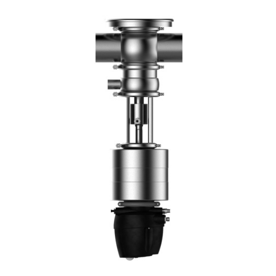
Seite 11: Aufbau Und Funktion
Aufbau und Funktion Design and Function Aufbau Design Es gibt 3 Ausführungsvarianten: There are 3 design variants: ohne Liftantrieb und mit Reinigungsanschluss without lifting actuator and with CIP connection T_RL mit Liftantrieb und mit Reinigungsanschluss T_RL with lifting actuator and with CIP connection T_RC mit Liftantrieb und ohne Reinigungsanschluss T_RC with lifting actuator and without CIP connection Doppelsitz-Bodenventil T_R... - Seite 12 Doppelsitz-Bodenventil T_RL Mixproof Bottom Valve T_RL – mit Liftantrieb – with lifting actuator – mit Reinigungsanschluss – with CIP connection 1 Steuerkopf 1 control top 2 Elektroanschluss für 2 electrical connection Versorgung for supply 3 Luftanschluss für 3 pneumatic connection Versorgung for supply 4 Antrieb...
- Seite 13 Doppelsitz-Bodenventil T_RC Mixproof Bottom Valve T_RC – mit Liftantrieb – with lifting actuator – ohne Reinigungsanschluss – without CIP connection (mit Leckanzeiger) (with leakage indicator) 1 Steuerkopf 1 control top 2 Elektroanschluss 2 electrical connection Versorgung for supply 3 Luftanschluss 3 pneumatic connection Versorgung for supply...
-
Seite 14: Funktion
Funktion Function Leckagegesicherte Absperr- Leakageproof shut-off funktion Bei den Ventilen T_R, T_RL und T_RC werden der Tank In valve T_R, T_RL und T_RC the tank and the valve und das Ventilgehäuse durch je einen Ventilsitz abge- housing are each fitted with a valve seat. schlossen. -
Seite 15: Reinigung Durch Liften
Cleaning by lifting Reinigung durch Liften During pipe CIP the valve disk in contact with the Während der Reinigung der Rohrleitung kann der mit cleaning liquid can be lifted individually. This allows Reinigungsflüssigkeit in Kontakt stehende Ventilteller the cleaning liquid to enter the isolation chamber and einzeln angeliftet werden. -
Seite 16: Einbau Und Betrieb
Einbau und Betrieb Assembly and Operation Darauf achten, dass – das Ventil spannungslos in das Rohrleitungssystem eingebaut wird und Make sure that – keine Gegenstände – the valve is installed in the pipe system free of stress (z. B. Werkzeuge, Schrauben) im System eingeschlos- sen sind. -
Seite 17: Gehäuseanschluss In Den Tank Einschweißen
Gehäuseanschluss in den Welding the housing con- Tank einschweißen nection into the tank HINWEIS NOTE Beim Einschweißen des When welding the hous- Gehäuseanschlusses T (1) ing connection T (1) into in den Tank muss eine the tank, use the welding Schweißvorrichtung (s. -
Seite 18: Gehäuse In Die Rohrleitung Einschweißen
Gehäuse in die Rohrlei- Welding the housing into tung einschweißen the pipe GEFAHR DANGER Wenn die Rohrleitungen/Tanks Flüssigkeiten enthalten, If liquids are running in the pipe system/tanks, they can können diese beim Öffnen herausspritzen und Men- gush out when it is opened and cause injury to people. schen verletzen. -
Seite 19: Pneumatischer Anschluss
VORSICHT CAUTION Bei der Montage des Ventils müssen die Gehäuse-O-Rin- When mounting the valve, make sure that the O-rings in ge immer gewechselt werden, damit die spätere Dicht- the housing are replaced to ensure the tightness of the heit des Ventils gegeben ist. valve. -
Seite 20: Verschlauchungsplan Steuerkopf T.vis
Verschlauchungsplan / Hosing diagramm Tuchenhagen Doppelsitz-Bodenventil T_RL/T_RC Datum/date: 2012-02-17 mit Steuerkopf T.VIS Mixproof bottom valve T_RL/T_RC with control top T.VIS Ansicht A View A zentrale Luftver- sorgung / Auslass central air supply Outlet Auslass Outlet Lift – Doppelteller Lift – double-disk Liftantrieb / lifting actuator Lift –... -
Seite 21: Verschlauchungsplan Ohne Steuerkopf
Datum:2012-04-17 Verschlauchungsplan Page: 1 of 2 Doppelsitzventile Typ R und T 221BAL009270DE_0.fm mit Liftantrieb ohne Anschlusskopf Anschluss 0 (0/C) Initiatoraufnahme INA/V für Anschluss 0 (mit Liftantrieb) A = Antrieb L = Liftantrieb P = zentrale Luftversorgung Y2 = Lift-Ventilteller Y3 = Lift-Doppelsitzteller Für einen optimalen Sitz am Luftanschluss ist es notwendig, die Pneumatikschläuche mit einem Schlauchschneider rechtwinklig... -
Seite 22: Hosing Diagramm Withoutcontrol Module
Datum:2012-04-17 Hosing diagram Page: 1 of 2 Mixproof Valves type R and T 221BAL009270EN_0.fm with lifting actuator without control module Proximity switch holder INA/V for actuator Actuator cover with cover with pneumatic connection 0 pneumatic connection 0 (0/C) (with lifting actuator) A = Actuator L = Lifting actuator P = Central air supply... -
Seite 23: Elektrischer Anschluss
Chap ter co ntinued „Mo unting the air ho se“: Fo rtsetzung d es Kap itels „Luftschlauch m o ntieren“: • Shut off the compressed air supply. • Druckluftversorgung abstellen. • Push the air hose into the air connector in the control •... -
Seite 24: Reinigung Und Passivierung
Cleaning and Reinigung und passivation Passivierung Cleaning Reinigung All parts in contact with product must be cleaned at reg- Alle produktberührten Teile müssen regelmäßig gerei- ular intervals. Always observe the safety data sheets nigt werden. Dabei sind die Sicherheitsdatenblätter der issued by the cleaning agent manufacturers. - Seite 25 Aus diesen Faktoren können verschiedene Kombinatio- These factors can be combined in such a way as to make nen gebildet werden, die ein optimales Reinigungser- an optimal cleaning result probable. gebnis wahrscheinlich machen. Reinigung des Leckageraums Cleaning of the leakage outlet system Die Reinigung des Leckageraums erfolgt über eine The leakage chamber is cleaned via a spray nozzle in the Sprühdüse im Doppelteller, die an eine Ventilsitzreini-...
-
Seite 26: Passivierung
Zuckerlösungen oder klebrige Medien bleiben oft an Sugar solutions or sticky media often adhere to surfaces den produktberührten Flächen z.B. dem Sitzring haften that come in contact with product, such as the seating und können dort auskristallisieren bevor sie durch ring, and may crystallise there before they can be clea- einen Liftvorgang abgereinigt werden. -
Seite 27: Störung, Ursache, Abhilfe
Störung, Ursache, Malfunction, Cause, Abhilfe Remedy VORSICHT CAUTION Bei Funktionsstörungen Ventil sofort abschalten und In the event of malfunctions immediately deactivate the gegen Einschalten sichern. Störungen dürfen nur von valve and secure it against inadvertent reactivation. qualifiziertem Personal unter Beachtung der Sicher- Defects may only be rectified by qualified personnel heitshinweise behoben werden. -
Seite 28: Instandhaltung
Instandhaltung Maintenance Inspektionen Inspections Zwischen den Instandhaltungsintervallen müssen die Within the maintenance periods, the valves must be Dichtheit und die Funktion der Ventile überwacht wer- checked for leakage and proper function. den. Produktberührte Dichtungen Product contact seals • Regelmäßig prüfen: •... -
Seite 29: Vor Der Demontage
Vor der Demontage Prior to dismantling the valve GEFAHR DANGER Vor dem Lösen der Rohranschlussverbindung und der Before detaching the pipe connection and the clamp Klemmverbindung der Ventilgehäuse müssen immer joint connections on the valve housings, always take the folgende Schritte durchgeführt werden: following preparatory measures: •... -
Seite 30: Ventil T_Rl Und T_Rc Demontieren
Dismantling valve T_RL and Ventil T_RL und T_RC T_RC demontieren • Reinigungsschlauch (2) • Unscrew the CIP hose abschrauben. (2). Steuerkopf Dismantlingthe abbauen control top • Halbringe am Steuer- • Remove the semi-annu- kopf (3) abnehmen. lar clamps at the control top (3). - Seite 31 Ventil vom Separating the Gehäuse valve from the trennen housing VORSICHT CAUTION Die Oberflächen der The surfaces of the Balancer (2) sind Dich- balancer (2) are sealing tungsflächen und dürfen surfaces and must not be nicht beschädigt werden. damaged. Beim Herausnehmen des Take care when removing Ventils aus der Leitung the valve from the pipe...
-
Seite 32: Ventileinsatz Vom Antrieb Trennen
Ventileinsatz Separating the vom Antrieb valve insert trennen and the actuator • Schaltstange (3), Schalt- stange (1) und Mutter • Unscrew switching rod (2), die miteinander ver- (3), switching rod (1) schraubt sind, mit Hilfe and nut (2) which are eines Dorns 4 mm aus screwed together from der Kolbenstange (10) - Seite 33 Liftantrieb Dismantling demontieren the lifting actuator • Spülanschluss (V9) von der Mitnehmerhülse • Draw-off rinsing con- (15) ziehen. nection (V9) from the drive sleeve (15). • Liftantrieb (4) zur Demontage hinlegen. • Put lifting actuator (4) down for further dis- •...
-
Seite 34: Ventil T_R Demontieren
Ventil T_R Dismantling demontieren valve T_R • Reinigungsschlauch • Unscrew the CIP hose. (22) abschrauben. (22). GEFAHR DANGER Beim Lösen der Klemm- When the clamp joints verbindung (23) am (23) at the housing of the Gehäuse des nicht ange- non-actuated valve are steuerten Ventils besteht detached, the released Verletzungsgefahr, da die... - Seite 35 • Withdraw valve insert • Ventileinsatz kompl. complete with actuator mit Antrieb (20) aus (20) from the housing dem Gehäuse (14) (14). herausziehen. Dismantling Steuerkopf the control top abbauen • Remove the clamp • Halbringe (12) entfer- joints (12). nen. •...
-
Seite 36: Wartung
Wartung Maintenance Ventil reinigen Cleaning the valve VORSICHT Ventiltellerschaft, Gehäu- CAUTION sesitz, Ventilsitz und The stem of the valve V-Ring-Nut sind Präzisi- disk, the housing seat, the onsbereiche. Sie dürfen valve seat and the V-ring nicht beschädigt werden! groove are precision parts which must not be •... - Seite 37 V-Ring wechseln Changing the V-ring Für den Einbau des Use the insertion tool V-Ringes das Einzieh- (part no. 229-109.88) to werkzeug (Sach-Nr. 229- mount the new V-ring. 109.88) verwenden. ✗ Do not grease the V-ring ✗ V-Ringe ohne Fett ein- before inserting it.
- Seite 38 V-Ring RA wechseln Changing the V-ring RA Für den Einbau des V-Ringes RA das Einzieh- Use the insertion tool to werkzeug verwenden. mount the new RA V-ring. ✗ ✗ V-Ringe RA ohne Fett Do not grease the V-ring einsetzen. Als Monta- RA before inserting it.
-
Seite 39: Dichtungen Und Gewinde Schmieren
The warrenty will become null and void. erlischt die Gewährleistung. A Manufacturer's Declaration for these products can be Bei Bedarf kann von GEA Tuchenhagen eine Hersteller- obtained from GEA Tuchenhagen if required. erklärung dieser Produkte angefordert werden. A thin film of grease is required on the seals to ensure Dünne Fettfilme auf den Dichtungen sind für eine ein-... - Seite 40 Ventil T_RL und T_RC Mounting the valve T_RL and montieren T_RC • Liftantrieb LFT-R (4) mit O-Ringen (5, 9, 16) • Equip the LFT-R lifting bestücken und mit actuator (4) with O-ring Klemmverbindung (11) (5, 9, 16) and fix it at the an der Laterne (14) lantern (14) using the befestigen.
- Seite 41 • Spülanschluss (V9) mit • Push rinsing connection O-Ringen (7) bestückt auf (V9) equipped with die Mitnehmerhülse (6) O-rings (7) on to the schieben. drive sleeve (6). Ventil T_RL Valve T_RL • Den Doppelteller (12) mit • Equip double-disk (12) V-Ringen (23, 24), Reini- with V-rings (23, 24), gungsdüse (13), Leckge-...
-
Seite 42: Sitzring Zwischen Gehäu- Sen Einsetzen
VORSICHT CAUTION Bei liegend eingebautem For horizontally installed Ventil besonders darauf valves take special care achten, dass das Gewicht that the weight of the des Ventils bei der Mon- valve is supported when tage abgefangen wird, dismounting the valve in um eine Beschädigung order to prevent damage von Sitzring und Ventil-... -
Seite 43: Ventil T_R Montieren
Ventil T_R montieren Mounting the valve T_R • Leckgehäuse (11) mit • Connect leakage hous- Dichtringen (2, 4), ing (11), complete with O-Ring (3), Lager (14) seal rings (2, 4), O-ring und Lagerscheibe (13) (3), bearing (14) and mit Klemmverbindung bearing disk (13) with (12) mit Laterne verbin- lantern using clamp... -
Seite 44: Hub Prüfen
Tightening torque lbft Drehmomente lbft Semi-annular clamps at the con- Halbringe am Steu- trol top erkopf Hinged clamps Klemmverbindung Hinged clamps 16,2 Klemmverbindung 16,2 Cast-semi-annular Guss-Halbringe clamp Checking the valve stroke Hub prüfen • Actuate the valve by applying compressed air. •... - Seite 45 Ventilgröße Gesamthub Lifthub Valve size Total valve Lifting stroke Doppelteller Ventilteller stroke C Double-disk Valve disk Ventil T_R Valve T_R Metrisch Metric DN 40 DN 40 DN 50 DN 50 DN 65 DN 65 DN 80 DN 80 DN 100 DN 100 DN 125 DN 125...
-
Seite 46: Technische Daten
Technische Daten Technical Data Baugröße DN 25 bis 150 Size DN 25 to 125 1" bis 4" OD 1" to 4" OD 2" bis 6" IPS 2" to 6" IPS Werkstoff der produkt- Edelstahl 1.4404 Material of product stainless steel 1.4404 berührenden Teile Korrosionsbeständigkeit contact parts... -
Seite 47: Rohrenden - Varivent -System
Rohrenden – VARIVENT -System ® Pipe ends – VARIVENT ® system Metrisch Außendurchmesser Wandstärke Innendurchmesser Außendurchmesser nach outside diameter wall thickness inside diameter outside diameter acc. to DIN 11850 Zoll OD Außendurchmesser Wandstärke Innendurchmesser Außendurchmesser nach Inch OD outside diameter wall thickness inside diameter outside diameter acc. -
Seite 48: Reinigungsanschluss
Reinigungsanschluss CIP connection Hose connection Anschluss für Schlauch DN 25/ 1" OD Ø 6/4 mm DN 25/ 1" OD Ø 6/4 mm DN 40...100, 2,5"...4" OD Ø 8/6 mm DN 40...100, 2,5"...4" OD Ø 8/6 mm DN 125, 150; 6" IPS Ø... -
Seite 49: Resistance Of The Sealing Material
Resistance of Sealing Materials The resistance of sealing materials depends on the type and temperature of the medium conveyed. The contact time can negatively affect the service life of the seals. The sealing materials comply with the regulations of FDA 21 CFR 177.2600 or FDA 21 CFR 177.1550. Medium Temperature Sealing material (general operating temperature) -
Seite 50: Werkzeugliste / Schmierstoff
Werkzeuglisten / Schmierstoff Lists of Tools / Lubricant Werkzeug / Tool Sach-Nr. / Part no. Schlauchschneider / Hose cutter 407-065 V-Ring-Einziehwerkzeug / V-ring insertion tool 229-109.88 Maulschlüssel abgeschliffen / Open spanner, ends ground, SW / size 17-19 229-119.01 Maulschlüssel abgeschliffen / Open spanner, ends ground, SW / size 21-23 229-119.05 Maulschlüssel abgeschliffen / Open spanner, ends ground, SW / size 22-24 229-119.03... - Seite 51 Data/date: 2016-09-09 Ersatzteilliste / Spare parts list Seite / Page 1 von / of 5 Doppelsitz-Bodenventil T_R Mixproof Bottom Valve T_R 221ELI001635G_9.DOC...
- Seite 52 Data/date: 2016-09-09 Ersatzteilliste / Spare parts list Seite / Page 2 von / of 5 Doppelsitz-Bodenventil T_R Mixproof Bottom Valve T_R 221ELI001635G_9.DOC Pos. Werkstoff Benennung / Designation DN 40 DN 50 DN 65 DN 80 DN 100 DN 125 DN 150 Material Item EPDM...
- Seite 53 Data/date: 2016-09-09 Ersatzteilliste / Spare parts list Seite / Page 3 von / of 5 Doppelsitz-Bodenventil T_R Mixproof Bottom Valve T_R 221ELI001635G_9.DOC Pos. Werkstoff Benennung / Designation 1 ½" OD 2" OD 2 ½" OD 3" OD 4" OD 6" OD Material Item EPDM...
- Seite 54 Data/date: 2016-09-09 Ersatzteilliste / Spare parts list Seite / Page 4 von / of 5 Doppelsitz-Bodenventil T_R Mixproof Bottom Valve T_R 221ELI001635G_9.DOC Pos. Werkstoff Benennung / Designation 2" IPS 3" IPS 4" IPS 6" IPS Item Material 221-000834 221-000836 221-000838 221-002827 EPDM Dichtungssatz / sealing set...
- Seite 55 Data/date: 2016-09-09 Ersatzteilliste / Spare parts list Seite / Page 5 von / of 5 Doppelsitz-Bodenventil T_R Mixproof Bottom Valve T_R 221ELI001635G_9.DOC Dichtungen für VARIVENT® Doppelsitzventil Typ T_R Seals for VARIVENT® Mixproof Valve Type T_R Stück Bezeichnung Werkstoff DN 40/50 DN 65/80 DN 100 DN150...
- Seite 56 Ersatzteilliste / Spare parts list Datum/date: 2016-06-28 Doppelsitz-Bodenventil T_RC Mixproof Bottom Valve T_RC 221ELI004791G_4.DOC Sach-Nr. / Part no. Werkstoff Pos. Benennung / Designation Item Material DN 25 1" OD EPDM 221-002613 221-002613 Dichtungssatz kpl. / 221-002614 221-002614 Sealing set cpl. HNBR 221-004342 221-004342...
- Seite 57 Data/date: 2016-03-30 Ersatzteilliste / Spare parts list Seite / Page 1 von / of 5 Doppelsitz-Bodenventil T_RC Mixproof Bottom Valve T_RC 221ELI001636G_12.DOC...
- Seite 58 Data/date: 2016-03-30 Ersatzteilliste / Spare parts list Seite / Page 2 von / of 5 Doppelsitz-Bodenventil T_RC Mixproof Bottom Valve T_RC 221ELI001636G_12.DOC Werkstoff Benennung / Designation DN 40 DN 50 DN 65 DN 80 DN 100 DN 125 DN 150 Item Material EPDM...
- Seite 59 Data/date: 2016-03-30 Ersatzteilliste / Spare parts list Seite / Page 3 von / of 5 Doppelsitz-Bodenventil T_RC Mixproof Bottom Valve T_RC 221ELI001636G_12.DOC Benennung / Pos. Werkstoff 1 ½" OD 2" OD 2 ½" OD 3" OD 4" OD 6" OD Designation Item Material...
- Seite 60 Data/date: 2016-03-30 Ersatzteilliste / Spare parts list Seite / Page 4 von / of 5 Doppelsitz-Bodenventil T_RC Mixproof Bottom Valve T_RC 221ELI001636G_12.DOC Werkstoff Benennung / Designation 2" IPS 3" IPS 4" IPS 6" IPS Item Material EPDM 221-000822 221-000824 221-000826 221-002829 Dichtungssatz / sealing set 221-000823...
- Seite 61 Data/date: 2016-03-30 Ersatzteilliste / Spare parts list Seite / Page 5 von / of 5 Doppelsitz-Bodenventil T_RC Mixproof Bottom Valve T_RC 221ELI001636G_12.DOC Dichtungen für VARIVENT® Doppelsitzventil Typ T_RC Seals for VARIVENT® Mixproof Valve Type T_RC Stück Bezeichnung Werkstoff DN 40/50 DN 65/80 DN 100 DN150...
- Seite 62 Datum / date: 2016-02-29 Ersatzteilliste / Spare parts list Seite / Page 1 von / of 5 Doppelsitz-Bodenventil T_RL 221ELI001637G_11.DOC Mixproof Bottom Valve T_RL...
- Seite 63 Datum / date: 2016-02-29 Ersatzteilliste / Spare parts list Seite / Page 2 von / of 5 Doppelsitz-Bodenventil T_RL 221ELI001637G_11.DOC Mixproof Bottom Valve T_RL Pos. Werkstoff Benennung / Designation DN 40 DN 50 DN 65 DN 80 DN 100 DN 125 DN 150 Item Material...
- Seite 64 Datum / date: 2016-02-29 Ersatzteilliste / Spare parts list Seite / Page 3 von / of 5 Doppelsitz-Bodenventil T_RL 221ELI001637G_11.DOC Mixproof Bottom Valve T_RL Pos. Benennung / Werkstoff 1 ½" OD 2" OD 2 ½" OD 3" OD 4" OD 6"...
- Seite 65 Datum / date: 2016-02-29 Ersatzteilliste / Spare parts list Seite / Page 4 von / of 5 Doppelsitz-Bodenventil T_RL 221ELI001637G_11.DOC Mixproof Bottom Valve T_RL Pos. Werkstoff Benennung / Designation 2" IPS 3" IPS 4" IPS 6" IPS Item Material EPDM 221-000828 221-000830 221-000832...
- Seite 66 Datum / date: 2016-02-29 Ersatzteilliste / Spare parts list Seite / Page 5 von / of 5 Doppelsitz-Bodenventil T_RL 221ELI001637G_11.DOC Mixproof Bottom Valve T_RL Dichtungen für VARIVENT® Doppelsitz-Bodenventil Typ T_RL Seals for VARIVENT® Mixproof Bottom Valve Type T_RL Pos. Stück Benennung / Werkstoff DN40/50...
- Seite 67 Datum / date : 2016-03-02 Ersatzteilliste / Spare parts list Seite / Page 1 von / of 1 Liftantrieb T / Lifting Actuator T für gebalancte Doppelsitz-Bodenventile TR_C und TR_L 221ELI002180G_3.DOC for balanced Mixproof Bottom Valves TR_C and TR_L Die mit * gekennzeichneten Pos. sind Verschleißteile. / Items marked with * are wearing parts. DN 80 DN 125 Werkstoff...
- Seite 68 Datum / Date: 2015-02-09 Ersatzteilliste und Maßblatt / Spare parts list and Dimension sheet ® ® VARIVENT / VARINLINE 221MBL007030G_2.DOC Gehäuseanschluss T und T-S / Ersatz für 221MBL002243G Housing Connection T and T-S Gehäuseanschluss T / Housing connection T -0,3 Gehäuseanschluss T-S / Housing connection T-S -0,3 Sach-Nr.
- Seite 69 Gehäuseanschluss T DN 25, DN 50/40, DN 80/65, DN 100 Gehäuseanschluss DN 50 T-S Schweißung der Decklage in 8 Segmentschritten Es darf nur Pulsschweißung angewandt werden Nahtarten: ∅...
- Seite 70 Housing Connection T DN 25; DN50/40; DN80/65; DN100 Housing Connection DN50 T-S Structure of the joint Welding procedure Welding of the final run in 8 segements Pulsed arc welding to be applied only weld seam ∅...
- Seite 71 Ersatzteilliste und Maßblatt / Datum/date : 2011-08-31 Spare parts list and dimension sheet Seite / Page 1 von / of 1 Gehäuseanschluss U / Housing Connection U 221mbl001334g_1.doc Gehäuseanschluss U-S 50/40 Werkstoff Benennung / Designation Sach-Nr. / Part No. Material U 25 U 50/40 U-S 50/40...
- Seite 72 Schweißanweisung des Herstellers ( WPS ) Datum: 2014-03-31 Gehäuseanschluss U 221RLI002533DE_2.doc Ort: Büchen Art der Vorbereitung: mechanisch Schweißverfahren d. Herstellers: 141 (WIG) - Puls Art der Reinigung: bürsten oder beizen, entgraten Schweißer: Prüfung nach DIN EN 287-1 Spezifikation der Grundwerkstoffe: 1.4404, 1.4435 AD-2000 Merkblatt HP3 Schweißprozess: 141 DIN EN ISO 4063 Vorgesehene Tankwanddicke [mm] t = 2;...
- Seite 73 Manufacturer’s Welding Instructions ( WPS ) for Datum: 2014-03-31 Housing Connection U 221RLI002534EN_2.doc Location: Büchen Preparation method: mechanical Manufacturer’s welding method: 141 ( WIG ) Cleaning method: brushing or pickling, degreasing Welders: qualified welder acc. to DIN EN 287-1 Specification of the parent metal: 1.4404, 1.4435 AD-2000 Merkblatt HP3 Welding procedure: 141 DIN EN ISO 4063 Workpiece thickness [mm]: t = 2;...
- Seite 75 2016-09 · Doppelsitz-Bodenventil T_R / T_RL / T_R / Mixproof Bottom Valve T_R / T_RL / T_RC...
- Seite 76 We live our values. Excellence Passion Integrity Responsibility GEA-versity GEA Group is a global engineering company with multi-billion euro sales and operations in more than 50 countries. Founded in 1881, the company is one of the largest providers of innovative equipment and process technology.