IFM Electronic Ecomat 100 Handbuch
Vorschau ausblenden
Andere Handbücher für Ecomat 100:
- Original-programmierhandbuch (307 Seiten) ,
- Handbuch (60 Seiten) ,
- Programmierhandbuch (39 Seiten)
Inhaltsverzeichnis
Verfügbare Sprachen
Verfügbare Sprachen
Quicklinks
Kapitel
Inhaltsverzeichnis

Verwandte Anleitungen für IFM Electronic Ecomat 100


Inhaltszusammenfassung für IFM Electronic Ecomat 100
- Seite 1 Geräte-Handbuch Device manual Neigungssensor 2-achsig Inclination sensor 2 axes CR2102...
-
Seite 2: Inhaltsverzeichnis
CR2102 NEIGUNGSSENSOR Sicherheitshinweise Diese Beschreibung ist Bestandteil des Gerätes. Sie enthält Texte und Abbildungen zum korrekten Umgang mit dem Modul und muß vor einer Installation oder dem Einsatz gelesen werden. Befolgen Sie die Angaben der Dokumentation. Nichtbeachten der Hinweise, Verwendung außerhalb der nachstehend genannten bestimmungsgemäßen Verwendung, falsche Installation oder Handhabung können Beeinträchtigun- gen der Sicherheit von Menschen und Anlagen zur Folge haben. -
Seite 3: Bestimmungsgemäße Verwendung / Funktion
CR2102 NEIGUNGSSENSOR Bestimmungsgemäße Verwendung / Funktion Der 2-achsige Neigungssensor mit CANopen-Schnittstelle ermöglicht die Winkel- nivellierung und Lageerfassung von mobilen Arbeitsmaschinen. Typische Applikationen sind z.B. die Lageerkennung von Arbeitsbühnen, die Mobilkrannivellierung oder die Einrichtung von mobilen Arbeitsmaschinen. Funktionsprinzip Zwei Messzellen, die nach dem konduktometrischen Prinzip arbeiten, werten die Leitfähigkeitsänderung einer Flüssigkeit aus. -
Seite 4: Technische Daten
CR2102 NEIGUNGSSENSOR Technische Daten Gehäuse Aluminium, schwarz eloxiert Trägerplatte Aluminium, natur Montage Befestigungsbohrungen für M5 Schrauben Schutzart IP 67 Anschluss M12-Steckverbinder für Betriebsspannung, CAN-Bus und Analogausgänge, 8-polig (Typ Lumberg) Betriebsspannung 10...30 V DC SELV ≤ 1,9 W Leistungsaufnahme Betriebstemperatur -30...+80°C Lagertemperatur - 40...+85°C (keine Schockbelastung unter -25°C) Messbereich (pro Achse) -
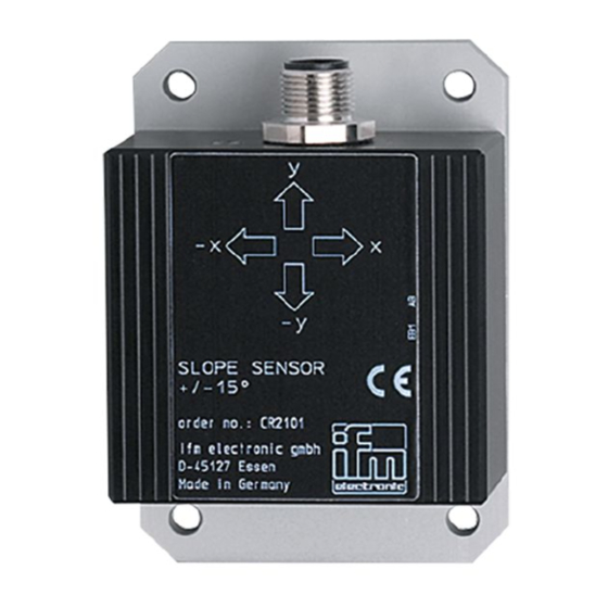
Seite 5: Montage
CR2102 NEIGUNGSSENSOR Montage Der Neigungssensor wird gemäß Darstellung mit Schrauben M5 x L (nach DIN 7500 bzw. DIN 7984) auf die zu nivellierenden bzw. zu erfassenden Vorrichtung befestigt. Um exakte Meßwerte zu erhalten, vermeiden Sie die Montage auf stark vibrierenden Vorrichtungen und sorgen Sie ggf. für eine ausreichende Schwin- gungsentkopplung. -
Seite 6: Parameter- Und Emcy-Objekt-Übersicht
CR2102 NEIGUNGSSENSOR Parameter- und EMCY-Objekt-Übersicht Über die Funktion „Restore“ (s. Objektverzeichnis, Index 1011) können die Para- meter mit den werkseitig hinterlegten Default-Werten belegt werden (Ausnahme Baudrate und Node-ID). Diese sind dann nach dem nächsten Einschalten der Ver- sorgungsspannung gültig. Parameterliste Index Defaultwert Änderung... -
Seite 7: Betriebsanzeige (Status-Led)
CR2102 NEIGUNGSSENSOR Life Time Factor 0 wird als 1 interpretiert. Bei einer Änderung der Anzeigeauflösung werden alle eventuell eingegebenen Offsetwerte bzw. Nullpunktwerte gelöscht. EMCY Objekte Folgende Fehlercodes gemäß DS-301 werden unterstützt: EMCY Error Zusatz Beschreibung Code Code 0x5010 0x21 0xxx Bereichsüber- oder unterschreitung des Neigungssensors. -
Seite 8: Objektverzeichnis
CR2102 NEIGUNGSSENSOR Objektverzeichnis Kommunikationsprofile; Index 1000 bis 1FFF Index S-Idx Name Default Beschreibung 1000 Device type u32, ro 0x8019A Profil 410; Inclinometer 1001 Error register u8, ro 0x00 Bitcodiert gemäß Profil 301; unterstützt wird: 0b 0000 0000 kein Fehler 0b 0000 0001 generic error 0b 0001 0000 communication error 0b 0010 0000 profile error 0b 1000 0000 manufacturer specific... - Seite 9 CR2102 NEIGUNGSSENSOR Kommunikationsprofile; Index 1000 bis 1FFF Index S-Idx Name Default Beschreibung 100D Life time factor u8, rw 0x00 Wenn für "guard time" * "life time" kein "node guarding" empfangen wird, generiert der Sensor ein EMCY und die rote LED leuchtet. Das Produkt aus "guard time"...
- Seite 10 CR2102 NEIGUNGSSENSOR Objektverzeichnis Kommunikationsprofile; Index 1000 bis 1FFF Index S-Idx Name Default Beschreibung 1800 Trans PDO 1 u8, ro 0x05 Anzahl der Einträge Trans PDO 1; Neigung Längs- und Querachse (X-/Y-Achse) COB-ID u32, rw 0x180 + - Bit 31 = 0 = PDO ist aktiviert Trans PDO 1 Node-ID - Bit 31 = 1 = PDO ist deaktiviert...
- Seite 11 CR2102 NEIGUNGSSENSOR Kommunikationsprofile; Index 1000 bis 1FFF Index S-Idx Name Default Beschreibung 1802 Trans PDO 3 u8, ro 0x05 Anzahl der Einträge Trans PDO 3; Neigung Querachse (Y-Achse) COB-ID u32, rw 0x380 + - Bit 31 = 0 = PDO ist aktiviert Trans PDO 3 Node-ID - Bit 31 = 1 = PDO ist deaktiviert...
-
Seite 12: Herstellerspezifische Profile; Index 2000 Bis 2Fff
CR2102 NEIGUNGSSENSOR Objektverzeichnis Herstellerspezifische Profile; Index 2000 bis 5FFF Index S-Idx Name Default Beschreibung 20F0 Einstellung u8, rw 0x20 Node-ID unter dem der Sensor im Node-ID (= 0d32) CANopen Netz angesprochen wird 20F1 Einstellung u8, rw 0x20 Node-ID unter dem der Sensor im Node-ID (= 0d32) CANopen Netz angesprochen wird... -
Seite 13: Geräteprofile; Index 6000 Bis 6Fff
CR2102 NEIGUNGSSENSOR Objektverzeichnis Geräteprofile; Index 6000 bis 6FFF Index S-Idx Name Default Beschreibung 6000 Resolution u16, rw 0d100 Anzeigeauflösung der Neigung für beide Achsen 100 = Neigung wird als signed int in 0,1° angegeben 500 = Neigung wird als signed int in 0,5°... - Seite 14 CR2102 NEIGUNGSSENSOR Objektverzeichnis Geräteprofile; Index 6000 bis 6FFF Index S-Idx Name Default Beschreibung 6014 Differential s16, rw 0x00 Verschiebt den Anzeigewert unabhängig Slope Long 16 vom „Slope Long 16 Preset Value“ Offset um den eingegebenen Wert. (s. hierzu Sensorparametrierung und -abgleich, Seite 15) 6020 Slope Lateral 16 s16, ro...
-
Seite 15: Sensorparametrierung Und -Abgleich
CR2102 NEIGUNGSSENSOR Sensorparametrierung und -abgleich Über die Werte „...Preset Value“ (Idx 60x2) und „Differential ...Offset“ (Idx 60x4) kann das Anzeigeverhalten der Längs- und Querachse beeinflußt werden. Der unter „...Preset Value“ eingegebene Wert korrigiert unmittelbar den zu die- sem Zeitpunkt t gemessenen Wert der Sensorzelle. -
Seite 16: Programmierung
CR2102 NEIGUNGSSENSOR Programmierung Allgemeines Der Neigungssensor muß als CANopen-Slave mit den CANopen-Startfunktionen „COP_MSTR_BOOTUP“ und „COP_MSTR_MAIN“ vom R 360-Master initialisiert und in den Zustand „OPERATIONAL“ versetzt werden (LED blinkt grün; 2 Hz). Programmier-Funktion Wird die Funktion „CR2102“ in das Programm eingebunden, sorgt diese auto- matisch für eine ständige Aktualisierung der X-/Y-Meßdaten in der Steuerung. - Seite 17 CR2102 NEIGUNGSSENSOR Im Programmablauf kann der Zugriff auf eine Strukturkomponente z.B. wie dar- gestellt erfolgen. Screenshot der CODESYS Programmieroberfläche Weitere CODESYS Programmierbeispiele für den Neigungssensor CR2102 erhalten Sie auf Nachfrage von der ifm electronic gmbh. SEITE...
- Seite 18 CR2102 NEIGUNGSSENSOR ■ Funktion: CR2102 CR2102 ■ Library: CR2102.lib ENABLE CFG_RESULT ■ Zweck: INIT IO_RCV Parametriert und liest NODE_ID die Konfigurations- und Meßwerte CFG_READ des 2-achsigen Neigungssensors CFG_WRITE CR2102 CFG_DATA RX_TYPE SYNC IO_DATA ■ Parameter Name Datentyp Beschreibung Eingänge ENABLE BOOL TRUE: Funktion wird abgearbeitet...
- Seite 19 CR2102 NEIGUNGSSENSOR ■ Datenstruktur: TYPE CR2102 ConfigStruct CR2102 ConfigStruct STRUCT GUARDTIME: TIME; ■ Zweck: LIFETIME: BYTE; Parameter- und Konfigurationsdaten Resolution: WORD; können geschrieben oder gelesen werden. ResolutionWriteEnable: BOOL; SlopeLongSign: BOOL; Die Datenstruktur wird dem Funktions- SlopeLongScaleEnable: BOOL; eingang „CFG_DATA“ über den ADR- SlopeLongPreset: INT;...
- Seite 20 CR2102 NEIGUNGSSENSOR Name Datentyp Beschreibung Längsachse (X) SlopeLong Errechneter Offset-Wert aus den eingegebenen Werten. Offset Offset-Wert = SlopeLongPreset t – gemessener Sensorwert t : Zeitpunkt, an dem der „SlopeLongPreset“ eingestellt wurde) Um den Wert auszulesen, muß „CFG_READ“ solange auf TRUE gesetzt werden, bis der Ausgang „CFG_RESULT“...
-
Seite 21: Wartung, Instandsetzung Und Entsorgung
CR2102 NEIGUNGSSENSOR ■ Datenstruktur: CR2102 InOutStruct TYPE CR2102 InOutStruct ■ Zweck: STRUCT SlopeLong: INT; Aktuelle Winkeldaten für beide Achsen SlopeLateral: INT; werden gelesen. END_STRUCT Die Datenstruktur wird dem Funktions- END_TYPE eingang „IO_DATA“ über den ADR- Operator zugewiesen. ■ Strukturkomponenten Name Datentyp Beschreibung SlopeLong... -
Seite 22: Begriffe Und Abkürzungen
CR2102 NEIGUNGSSENSOR Begriffe und Abkürzungen 0b ... binärer Zahlenwert (zur Bitcodierung), z.B. 0b0001 0000 0d ... dezimaler Zahlenwert, z.B. 0d100 0x ... hexadezimaler Zahlenwert, z.B. 0x64 (= 100 dezimal) Baudrate Übertragungsgeschwindigkeit (1 Baud = 1 Bit/sec.) CAN Application Layer CAN basierendes Netzwerkprotkoll auf Applikationsebene Controller Area Network (Bussystem für den Einsatz im Mobilbereich) CAN_H CAN-High;... - Seite 23 CR2102 NEIGUNGSSENSOR Node Guarding Parametrierbare zyklische Überwachung von Slave-Netzwerkteilnehmern durch einen übergeordneten Master-Knoten, sowie die Überwachung dieses Abfragemechanismus durch die Slave-Teilnehmer. Node-ID Knotenpunkt-Identifier (Kennung eines Teilnehmers im CANopen Netz) Objekt (auch OBJ) Oberbegriff für austauschbare Daten/Botschaften innerhalb des CANopen- Netzwerks Objektverzeichnis enthält alle CANopen-Kommunikationsparameter eines Gerätes, sowie gerä- tespezifische Parameter und Daten.