Herunterladen Inhalt Inhalt Diese Seite drucken
bürkert TopControl Basic 8696 Schnellstartanleitung

bürkert TopControl Basic 8696 Schnellstartanleitung

Elektropneumatischer stellungsregler
Vorschau ausblenden Andere Handbücher für TopControl Basic 8696:
Inhaltsverzeichnis

Werbung

Verfügbare Sprachen

Verfügbare Sprachen

Type 8696
Positioner TopControl Basic
Electropneumatic Position Controller
Elektropneumatischer Stellungsregler
Positionneur électropneumatiques
Quickstart
English
Deutsch
Français

Werbung

Inhaltsverzeichnis
loading

Inhaltszusammenfassung für bürkert TopControl Basic 8696

  • Seite 1 Type 8696 Positioner TopControl Basic Electropneumatic Position Controller Elektropneumatischer Stellungsregler Positionneur électropneumatiques Quickstart English Deutsch Français...
  • Seite 2 We reserve the right to make technical changes without notice. Technische Änderungen vorbehalten. Sous réserve de modifications techniques. © 2007 - 2013 Bürkert Werke GmbH Quickstart 1304/03_EU-ML_00805654 / Original DE...
  • Seite 3: Inhaltsverzeichnis

    Type 8696 Table of Contents 7. installation ....................12 1. Quickstart .....................4 7.1. Safety instructions .................12 1.1. Definition of term “Device” ............. 4 7.2. Installation of the positioner on process valves of 1.2. Symbols ....................4 series 2103 and 23xx ..............12 2. authorized use ..................5 8. fluid installation .
  • Seite 4: Quickstart

    Type 8696 Quickstart QuicksTarT 1.2. symbols The operating instructions describe the entire life cycle of the device. The following symbols are used in these instructions. Keep these instructions in a location which is easily accessible to Danger! every user and make these instructions available to every new owner of the device.
  • Seite 5: Authorized Use

    Type 8696 Authorized use auThorizeD use Basic safeTy insTrucTions These safety instructions do not make allowance for any non-authorized use of the positioner type 8696 may be a hazard to people, nearby equipment and the environment. • contingencies and events which may arise during the installation, operation and maintenance of the devices. • The device is designed to be mounted on pneumatic actuators of process valves for the control of media.
  • Seite 6 Type 8696 Basic safety instructions note! General hazardous situations. To prevent injury, ensure: electrostatic sensitive components / modules! • Installation and repair work may be carried out by authorized The device contains electronic components which react sensitively technicians only and with the appropriate tools. to electrostatic discharge (ESD). Contact with electrostatically •...
  • Seite 7: General Information

    Type 8696 General information General informaTion sysTem DescripTion 4.1. contact address 5.1. structure and function germany Bürkert Fluid Control System Positioner Sales Center Chr.-Bürkert-Str. 13-17 D-74653 Ingelfingen Tel. + 49 (0) 7940 - 10 91 111 Fax + 49 (0) 7940 - 10 91 448 E-mail: info@de.buerkert.com Actuator international Contact addresses can be found on the final pages of the printed...
  • Seite 8: Model For Control Of Third-Party Devices

    Type 8696 System description 5.2. model for control of third-party Electrical connection devices (circular plug-in connector) A special model enables the positioner Type 8696 to be attached to third-party devices. Pilot air port This model has a different pneumatic connection module so that the (label: 1) pilot air ports can be connected to the outside of the actuator.
  • Seite 9: Technical Data

    Type 8696 Technical data Technical DaTa “In rest position” means that the pilot valves of the positioner Type 8696 are isolated or not actuated. 6.1. conformity In accordance with the EC Declaration of conformity, the positioner If the ambient air is humid, a hose can be connected between Type 8696 is compliant with the EC Directives.
  • Seite 10: Mechanical Data

    Type 8696 Technical data 6.4. mechanical data 6.6. pneumatic data Dimensions See data sheet Control medium: neutral gases, air Quality classes in accordance with DIN ISO Body material exterior: PPS, PC, VA 8573-1 interior: PA6; ABS Dust content Class 5: max. particle size 40 µm, Sealing material EPDM / FKM max.
  • Seite 11: Electrical Data

    Type 8696 Technical data 6.7. electrical data 6.8. factory settings of the positioner Connections Circular plug-in connector (M12 x 1, 8-pole) Functions can be activated via DIP switches: Pilot valve Supply voltage 24 V DC ± 10% function parameter Value - max. residual ripple 10 % ≤ 3.5 W Power input CUTOFF Sealing function below...
  • Seite 12: Installation

    Type 8696 Installation insTallaTion 7.2. installation of the positioner on process valves of series 2103 and Only for positioner without pre-assembled process valve. 23xx Procedure: When the positioner is being installed, the collets of the pilot 7.1. safety instructions air ports must not be fitted to the actuator. Danger! → Align the puck holder and the positioner until 1.
  • Seite 13: Fluid Installation

    Type 8696 Fluid installation → fluiD insTallaTion Push the positioner, without turning it, onto the actuator until no gap is visible on the form seal. 8.1. safety instructions note! Danger! too high torque when screwing in the fastening screw does not ensure protection class ip65 / ip67! risk of injury from high pressure! • The fastening screws may be tightened to a maximum torque of •...
  • Seite 14: Installing The Process Valve

    Type 8696 Fluid installation 8.2. installing the process valve Keep the adjacent supply pressure always at least 0.5 – 1 bar above the pressure which is required to move the actuator Thread type and dimensions can be found in the corresponding data to its end position. This ensures that the control behavior is sheet.
  • Seite 15: Electrical Installation

    Type 8696 Electrical installation elecTrical insTallaTion Important information for the problem-free functioning of the device: 9.1. safety instructions • The installation must not cause back pressure to build up. Danger! • Select a hose for the connection with an adequate cross-section. risk of electric shock! • The exhaust air line must be designed in such a way that •...
  • Seite 16: Electrical Installation With Circular Plug-In Connector

    Type 8696 Start-up 9.2. e lectrical installation with circular 10. sTarT-up plug-in connector 10.1. safety instructions → Connect the positioner according to the table. Warning! risk of injury from improper operation! Improper operation may result in injuries as well as damage to the device and the area around it. • Before start-up, ensure that the operating personnel are familiar with and completely understand the contents of the operating instructions.
  • Seite 17 Type 8696 Start-up note! Key 1 X.TUNE X.TUNE STARTED avoid maladjustment of the controller due to an incorrect pilot pressure or applied operating medium pressure! TUNE #0 • Run X.TUNE whenever the pilot pressure (= pneumatic auxil- INIT iary energy) is available during subsequent operation. • Run the X.TUNE function preferably without operating medium pressure to exclude interference caused by flow forces. X.TUNE READY To run X.TUNE, the positioner must be in the AUTOMATIC...
  • Seite 18: Control And Display Elements

    Type 8696 Start-up 10.3. c ontrol and display elements 10.3.1. operating status AUTOMATIC (AUTO) A detailed description of the operation and functions of the positioner and the communication software can be found in Normal controller mode is implemented and monitored in AUTO- the respective operating instructions. MATIC operating state.
  • Seite 19: Functions Of The Keys

    Type 8696 Start-up 10.3.2. functions of the keys 10.3.3. function of the Dip switches The configuration of the 2 keys on the board varies depending on the operating status (AUTOMATIC / MANUAL). dip function switches Key 1 1 2 3 4 Reversal of the effective direction of the set-point value (set-point value 20 –...
  • Seite 20: Display Of The Leds

    Type 8696 Start-up 10.3.4. Display of the leDs led 1 (green / red) LeD States Display green LED 2 Acceleration phase when Power ON flashes slowly Operating status AUTO (AUTOMATIC) LED 1 flashing flashing MANUAL operating status alternating flashes quickly X.TUNE function ERROR (see operating instructions) flashing flashing AUTO operating status for sensor break detection slow Tab.
  • Seite 21: Safety Positions

    Type 8696 Safety positions 11. safeTy posiTions 12. accessories designation order no. safety positions after failure of the auxiliary USB adapter for connection to a PC in con- actuator 227093 designation power junction with an extension cable system electrical pneumatic Communications software based on FDT/ Information at DTM technology www.burkert.com Connection cable M12 x 1, 8-pole 919061...
  • Seite 22: Packaging, Transport, Storage

    Type 8696 Packaging, transport, storage 13. packaGinG, TransporT, sToraGe note! transport damages! Inadequately protected equipment may be damaged during transport. • During transportation protect the device against wet and dirt in shock-resistant packaging. • Avoid exceeding or dropping below the permitted storage temperature. incorrect storage may damage the device. • Store the device in a dry and dust-free location! •...
  • Seite 23 Typ 8696 Inhaltsverzeichnis 7. montaGe ......................32 1. der Quickstart ..................24 7.1. Sicherheitshinweise ...............32 1.1. Begriffsdefinition Gerät ..............24 7.2. Montage Positioner an Prozessventile der Reihe 2103 1.2. Darstellungsmittel ................24 und 23xx ....................32 2. BestimmunGsGemässe VerWendunG ........25 8. fluidische installation ..............33 2.1.
  • Seite 24: Der Quickstart

    Typ 8696 Der Quickstart Der QuicksTarT 1.2. Darstellungsmittel Der Quickstart beschreibt den gesamten Lebenszyklus des Geräts. In dieser Anleitung werden folgende Darstellungsmittel verwendet. Bewahren Sie diese Anleitung so auf, dass sie für jeden Benutzer gut gefahr! zugänglich ist und jedem neuen Eigentümer des Geräts wieder zur Verfügung steht.
  • Seite 25: Bestimmungsgemässe Verwendung

    Typ 8696 Bestimmungsgemäße Verwendung BesTimmunGsGemässe GrunDleGenDe VerWenDunG sicherheiTshinWeise Diese Sicherheitshinweise berücksichtigen keine Bei nicht bestimmungsgemäßem einsatz des positioners typ 8696 können Gefahren für personen, anlagen in der • Zufälligkeiten und Ereignisse, die bei Montage, Betrieb und Wartung umgebung und die umwelt entstehen. der Geräte auftreten können. • Das Gerät ist für den Anbau an pneumatische Antriebe von Pro- • ortsbezogenen Sicherheitsbestimmungen, für deren Einhaltung, auch zessventilen zur Steuerung von Medien konzipiert.
  • Seite 26 Typ 8696 Grundlegende Sicherheitshinweise hinWeiS! allgemeine Gefahrensituationen. Zum Schutz vor Verletzungen ist zu beachten: elektrostatisch gefährdete Bauelemente / Baugruppen! • Dass die Anlage nicht unbeabsichtigt betätigt werden kann. Das Gerät enthält elektronische Bauelemente, die gegen elekt- • Installations- und Instandhaltungsarbeiten dürfen nur von auto- rostatische Entladung (ESD) empfindlich reagieren. Berührung risiertem Fachpersonal mit geeignetem Werkzeug ausgeführt mit elektrostatisch aufgeladenen Personen oder Gegenständen werden.
  • Seite 27: Allgemeine Hinweise

    Typ 8696 Allgemeine Hinweise allGemeine hinWeise sysTemBeschreiBunG 4.1. kontaktadresse 5.1. aufbau und funkion Deutschland Bürkert Fluid Control Systems Positioner Sales Center Christian-Bürkert-Str. 13-17 D-74653 Ingelfingen Tel. + 49 (0) 7940 - 10 91 111 Fax + 49 (0) 7940 - 10 91 448 E-mail: info@de.buerkert.com Antrieb international Prozessventil...
  • Seite 28: Variante Zur Ansteuerung Von Fremdgeräten

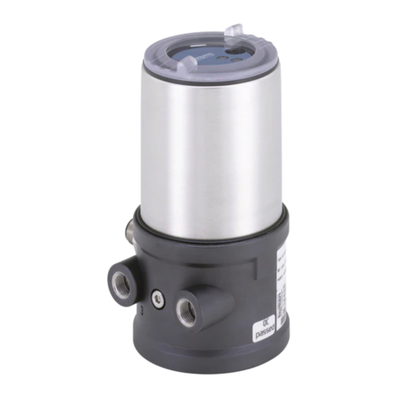
    Typ 8696 Systembeschreibung 5.2. Variante zur ansteuerung von Elektrischer Anschluss fremdgeräten (Rundsteckverbinder) Mit einer speziellen Variante kann der Positioner Typ 8696 an Fremd- geräte angebaut werden. Steuerluftanschluss Diese Variante besitzt ein anderes pneumatisches Anschlussmodul, (Beschriftung: 1) damit die Steuerluftanschlüsse extern angeschlossen werden können. Abluftanschluss Elektrischer Anschluss (Beschriftung: 3) Rundsteckverbinder M12 x 1...
  • Seite 29: Technische Daten

    Typ 8696 Technische Daten Technische DaTen „In Ruhestellung“ bedeutet, dass das Steuerventil des Positi- oners Typ 8696 stromlos bzw. nicht betätigt ist. 6.1. konformität Der Positioner Typ 8696 ist konform zu den EG-Richtlinien entspre- Bei feuchter Umgebungsluft kann eine Schlauchverbindung chend der EG-Konformitätserklärung. zwischen Steuerluftausgang 2 des Positioners und dem 6.2. normen...
  • Seite 30: Mechanische Daten

    Typ 8696 Technische Daten 6.4. mechanische Daten 6.6. pneumatische Daten Abmessungen siehe Datenblatt Steuermedium neutrale Gase, Luft Qualitätsklassen nach DIN ISO 8573-1 Gehäusematerial außen: PPS, PC, VA, innen: PA 6; ABS Staubgehalt Klasse 5 max. Teilchengröße 40 µm, max. Teilchendichte 10 mg/m³ Dichtungsmaterial EPDM / FKM Wassergehalt Klasse 3 max.
  • Seite 31: Elektrische Daten

    Typ 8696 Technische Daten 6.7. elektrische Daten 6.8. Werkseinstellungen des positioners Anschlüsse Rundsteckverbinder (M12 x 1, 8-polig) Über DIP-Schalter aktivierbare Funktionen: Steuerventil Betriebsspannung 24 V DC ± 10 % max. Restwelligkeit 10 % funktion parameter Wert ≤ 3,5 W Leistungsaufnahme Eingangswiderstand CUTOFF Dichtschließfunktion unten für Sollwertsignal 180 Ω...
  • Seite 32: Montage

    Typ 8696 Montage monTaGe 7.2. montage positioner an prozessventile der reihe 2103 und 23xx Nur für Positioner ohne vormontiertes Prozessventil. Vorgehensweise: Bei der Montage des Positioners dürfen die Collets der Steu- erluftanschlüsse am Antrieb nicht montiert sein. 7.1. sicherheitshinweise → Den Puckhalter und den Positioner so ausrichten, dass gefahr! 1.
  • Seite 33: Fluidische Installation

    Typ 8696 Fluidische Installation → fluiDische insTallaTion Den Positioner ohne Drehbewegung soweit auf den Antrieb schieben, dass an der Formdichtung kein Spalt mehr sichtbar ist. 8.1. sicherheitshinweise hinWeiS! gefahr! durch ein zu hohes drehmoment beim einschrauben der Befestigungsschraube kann die schutzart ip65 / ip67 nicht Verletzungsgefahr durch hohen druck in der anlage! sichergestellt werden! • Vor dem Lösen von Leitungen und Ventilen den Druck abschal- •...
  • Seite 34: Installation Des Prozessventils

    Typ 8696 Fluidische Installation 8.2. installation des prozessventils Wichtiger Hinweis zur einwandfreien Funktion des Geräts: Gewindeart und Abmessungen sind dem entsprechenden Datenblatt • Durch die Installation darf sich kein Rückdruck aufbauen. zu entnehmen. • Für den Anschluss einen Schlauch mit ausreichendem → Das Prozessventil entsprechend der Bedienungsanleitung des Querschnitt wählen.
  • Seite 35: Elektrische Installation

    Typ 8696 Elektrische Installation 9.2. e lektrische installation mit elekTrische insTallaTion rundsteckverbinder 9.1. sicherheitshinweise → Den Positioner entsprechend der Tabelle anschließen. gefahr! Verletzungsgefahr durch elektrische spannung! • Vor Eingriffen in das System die Spannung abschalten und vor Wiedereinschalten sichern! • Die geltenden Unfallverhütungs- und Sicherheitsbestimmungen für elektrische Geräte beachten! Bild 8: Belegung Rundstecker (M12 x 1, 8-polig) Warnung!
  • Seite 36: Inbetriebnahme

    Typ 8696 Inbetriebnahme 10. inBeTrieBnahme hinWeiS! 10.1. sicherheitshinweise durch einen falschen steuerdruck oder aufgeschalteten Betriebsdruck am Ventilsitz kann es zur fehlanpassung des Warnung! reglers kommen! • X.TUNE in jedem fall bei dem im späteren Betrieb zur Ver- Verletzungsgefahr bei unsachgemäßem Betrieb! fügung stehenden Steuerdruck (= pneumatische Hilfsenergie) Nicht sachgemäßer Betrieb kann zu Verletzungen, sowie Schäden durchführen. am Gerät und seiner Umgebung führen. •...
  • Seite 37: Bedienung Und Anzeigeelemente

    Typ 8696 Inbetriebnahme 10.3. B edienung und anzeigeelemente Taste 1 ca. 5 s X.TUNE X.TUNE STARTED Eine detaillierte Beschreibung der Bedienung und Funktionen des Positioners und der Kommunikationssoftware finden Sie TUNE #0 in der jeweiligen Bedienungsanleitung. INIT → Die Klarsichthaube des Positioners abschrauben, um die Tasten und DIP-Schalter zu bedienen.
  • Seite 38: Betriebszustand

    Typ 8696 Inbetriebnahme 10.3.1. Betriebszustand 10.3.2. funktionen der Tasten Die Belegung der 2 Tasten sind je nach Betriebszustand (AUTOMATIK AUTOMATIK / HAND) unterschiedlich. Im Betriebszustand AUTOMATIK wird der normale Reglerbetrieb Taste 1 ausgeführt und überwacht. LED 1 blinkt grün. HAND Taste 2 Im Betriebszustand HAND kann das Ventil manuell über die Tasten auf- oder zugefahren werden.
  • Seite 39: Funktion Der Dip-Schalter

    Typ 8696 Inbetriebnahme 10.3.3. funktion der Dip-schalter 10.3.4. anzeige der leDs dip- LED 2 funktion schalter 1 2 3 4 LED 1 Umkehr der Wirkrichtung des Sollwertes (20 ... 4 mA entspricht 0 ... 100 %), fallend (DIR.CMD) normale Wirkrichtung des Sollwertes (4 ... 20 mA entspricht 0 ... 100 %), steigend Dichtschließfunktion aktiv.
  • Seite 40: Sicherheitsstellungen

    Typ 8696 Sicherheitsstellungen 11. sicherheiTssTellunGen led 1 (grün / rot) LED-Zustände Anzeige sicherheitsstellung nach grün ausfall der hilfsenergie Hochlaufphase bei Power ON antriebssart Bezeichnung pneuma- blinkt langsam Betriebszustand AUTO elektrisch tisch blinkt blinkt Betriebszustand HAND im Wechsel einfach- blinkt schnell X.TUNE Funktion wirkend nicht FEHLER (siehe down definiert Steuer- Bedienungsanleitung) funktion A...
  • Seite 41: Zubehör

    Typ 8696 Zubehör 12. zuBehör 13. TransporT, laGerunG, VerpackunG Bezeichnung Bestell-nr. hinWeiS! USB-Adapter zum Anschluss eines PC in 227093 Verbindung mit einem Verlängerungskabel transportschäden! Unzureichend geschützte Geräte können durch den Transport Kommunikationssoftware auf FDT/DTM Infos unter beschädigt werden. Technologie www.buerkert.de • Gerät vor Nässe und Schmutz geschützt in einer stoßfesten Anschlusskabel M12 x 1, 8-polig 919061 Verpackung transportieren.
  • Seite 42 Typ 8696 Transport, Lagerung, Verpackung deutsch...
  • Seite 43 Type 8696 Sommaire 7. montaGe ......................52 1. Quickstart ....................44 7.1. Consignes de sécurité ..............52 1.1. Définition du terme « appareil » ...........44 7.2. Montage du positionneur type 8696 sur les vannes 1.2. Symboles..................44 process des séries 2103 et 23xx ..........52 2. utilisation conforme...............
  • Seite 44: Quickstart

    Type 8696 Quickstart QuicksTarT 1.2. symboles Quickstart décrit le cycle de vie complet de l’appareil. Conservez-le Les moyens de représentation suivants sont utilisés dans les présentes instructions de service. de sorte qu’il soit accessible à tout utilisateur et à disposition de tout nouveau propriétaire.
  • Seite 45: Utilisation Conforme

    Type 8696 Utilisation conforme uTilisaTion conforme consiGnes De sécuriTé fonDamenTales l’utilisation non conforme du positionneur type 8696 peut présenter des dangers pour les personnes, les installations Ces consignes de sécurité ne tiennent pas compte proches et l’environnement. • des hasards et des événements pouvant survenir lors du montage, • L’appareil est conçu pour être monté sur les actionneurs pneu- de l’exploitation et de l’entretien des appareils. matiques des vannes process pour la commande de fluides.
  • Seite 46 Type 8696 Consignes de sécurité fondamentales remarque ! situations dangereuses d’ordre général. Pour prévenir les blessures, respectez ce qui suit : éléments /sous-groupes sujets aux risques électrostatiques. • L’installation ne peut pas être actionnée par inadvertance. L‘appareil contient des éléments électroniques sensibles aux • Les travaux d’installation et de maintenance doivent être décharges électrostatiques (ESD).
  • Seite 47: Indications Générales

    Type 8696 Indications générales inDicaTions Générales DescripTion Du sysTème 4.1. adresse 5.1. structure et mode de fonctionnement allemagne Bürkert Fluid Control System Positionneur Sales Center Chr.-Bürkert-Str. 13-17 D-74653 Ingelfingen Tél. : + 49 (0) 7940 - 10 91 111 Fax : + 49 (0) 7940 - 10 91 448 E-mail : info@de.buerkert.com Actionneur international...
  • Seite 48: Variante De Commande Des Appareils Étrangers

    Type 8696 Description du Système 5.2. Variante de commande des Raccordement électrique appareils étrangers (connecteur rond) Une variante spéciale permet de monter le positionneur type 8690 sur les appareils étrangers. Raccord d’air de pilotage Cette variante est dotée d’un autre module de raccordement pneu- (Légende : 1) matique permettant le raccordement externe des raccords d’air de pilotage à...
  • Seite 49: Caractéristiques Techniques

    Type 8696 Caractéristiques techniques caracTérisTiQues TechniQues « En position de repos » signifie que les vannes pilote de la positionneur type 8696 ne sont pas alimentées en courant ou 6.1. conformité ne sont pas activées. Le positionneur type 8696 est conforme aux directives CE sur la base de la déclaration de conformité...
  • Seite 50: Caractéristiques Mécaniques

    Type 8696 Caractéristiques techniques 6.4. caractéristiques mécaniques 6.6. caractéristiques pneumatiques Cotes voir fiche technique Fluide de commande gaz neutres, air Classes de qualité selon DIN ISO 8573-1 Matériau du corps extérieur : PPS, PC, VA intérieur : PA6; ABS Teneur en poussières Classe 5 Taille maximale des particules 40 µm, densité...
  • Seite 51: Caractéristiques Électriques

    Type 8696 Caractéristiques techniques 6.7. caractéristiques électriques 6.8. réglages usine du positionneur Raccordements Connecteur rond (M12 x 1, 8 pôles) Fonctions activables avec interrupteur DIP : Vanne pilote tension d’alimentation 24 V DC ± 10 % - ondulation résiduelle maxi 10 % fonction paramètre Valeur ≤ 3,5 W puissance absorbée Résistance d‘entrée CUTOFF...
  • Seite 52: Montage

    Type 8696 Montage monTaGe 7.2. montage du positionneur type 8696 sur les vannes process des séries Uniquement pour positionneur sans vanne process 2103 et 23xx prémontée. Lors du montage du positionneur, les collets des raccords d’air 7.1. consignes de sécurité de pilotage ne doivent pas être montés sur l’actionneur. → Danger ! Disposer le support de rouleau presseur et le positionneur de façon danger dû à la haute pression.
  • Seite 53: Installation Fluidique

    Type 8696 Installation fluidique → insTallaTion fluiDiQue Glisser le positionneur sur l’actionneur sans la faire tourner jusqu’à ce que le joint profilé ne présente plus d’interstice. 8.1. consignes de sécurité remarque ! Danger ! le type de protection ip65 / ip67 ne peut être garanti si le couple de serrage de la vis de fixation est trop élevé. danger dû à la haute pression. • Les vis de fixation doivent être serrées uniquement avec un •...
  • Seite 54: Installation De La Vanne Process

    Type 8696 Installation fluidique 8.2. installation de la vanne process Maintenez la pression d’alimentation appliquée absolument à au moins 0,5 ... 1 bar au-dessus de la pression nécessaire pour Le type de filet et les dimensions peuvent être consultés dans la fiche amener l’actionneur dans sa position finale. De cette façon, technique correspondante.
  • Seite 55: Installation Électrique

    Type 8696 Installation électrique insTallaTion élecTriQue 9.1. consignes de sécurité Danger ! risque de blessures par la tension électrique. • Avant d'intervenir dans le système, coupez la tension et empêchez Fig. 8 : Connecteur rond M12 x 1, 8-pôles toute remise sous tension par inadvertance. couleur • Veuillez respecter les réglementations en vigueur pour les appareils Broche affectation de fil...
  • Seite 56: Mise En Service

    Type 8696 Mise en service 10. mise en serVice remarque ! 10.1. consignes de sécurité evitez une mauvaise adaptation du régulateur suite à une pression de pilotage ou une pression de fluide de service erronée. aVertiSSement ! • Exécutez dans tous les cas X.TUNE avec la pression de pilotage disponible lors du fonctionnement ultérieur (= énergie auxiliaire risque de blessures dû à un montage non conforme.
  • Seite 57: Eléments De Commande Et D'affichage

    Type 8696 Mise en service 10.3. e léments de commande et Touche 1 X.TUNE d’affichage X.TUNE STARTED Une description détaillée de la commande et des fonctions du positionneur et du logiciel de communication est décrite TUNE #0 INIT dans les manuels d’utilisation respectifs. → Pour commander les touches et les interrupteurs DIP, dévisser le X.TUNE capot transparent.
  • Seite 58: Etat De Marche

    Type 8696 Mise en service 10.3.1. etat de marche Touche 1 AUTOMATIQUE (AUTO) A l’état de marche AUTOMATIQUE, le fonctionnement normal du régulateur est effectué et surveillé. Touche 2 La LED 1 clignote en vert. MANUEL (MANU) Fig. 12 : Touches A l’état de marche MANUEL, la vanne peut être ouverte ou fermée Etat de marche MANUEL (interrupteur DIP 4 sur ON) : manuellement à...
  • Seite 59: Fonction Des Interrupteurs Dip

    Type 8696 Mise en service 10.3.3. fonction des interrupteurs Dip 10.3.4. affichage des leD interrup- LED 2 fonction teurs dip 1 2 3 4 LED 1 Inversion du sens d’action de la valeur de consigne (la valeur de consigne 20 ... 4 mA correspond à la position 0 ... 100 %), vers le bas (DIR.CMD) sens d’action normal de la valeur de consigne (la valeur de consigne 4 ...
  • Seite 60 Type 8696 Mise en service led 1 (vert / rouge) led 2 (vert / jaune) etats des LeD etats des LeD affichage affichage vert rouge vert jaune allumée éteinte allumée éteinte actionneur fermé Phase de démarrage pour Power ON clignote éteinte Etat de marche AUTO éteinte allumée actionneur ouvert lentement (AUTOMATIQUE) clignote Écart de régulation permanent éteinte...
  • Seite 61: Positions De Sécurité

    Type 8696 Positions de sécurité 11. posiTions De sécuriTé 12. accessoires n° de désignation réglages de sécurité commande après une panne de type Adaptateur USB pour le raccordement d'un l’énergie auxiliaire désignation 227093 d’actionneur PC en liaison avec un câble de rallonge pneuma- électrique Logiciel de communication sur technologie Infos sous tique FDT/DTM www.buerkert.fr Câble de raccordement M12 x1, 8 pôles...
  • Seite 62: Emballage, Transport, Stockage

    Type 8696 Emballage, transport, Stockage 13. emBallaGe, TransporT, sTockaGe remarque ! dommages dus au transport. Les appareils insuffisamment protégés peuvent être endommagés pendant le transport. • Transportez l'appareil à l'abri de l'humidité et des impuretés et dans un emballage résistant aux chocs. • Évitez le dépassement vers le haut ou le bas de la température de stockage admissible.
  • Seite 64 www.burkert.com...

Inhaltsverzeichnis