Herunterladen Inhalt Inhalt Diese Seite drucken
bürkert 8696 Schnellstart

bürkert 8696 Schnellstart

Elektropneumatischer stellungsregler
Vorschau ausblenden Andere Handbücher für 8696:
Inhaltsverzeichnis

Werbung

Verfügbare Sprachen

Verfügbare Sprachen

Type 8696
Positioner TopControl Basic
Electropneumatic Position Controller
Elektropneumatischer Stellungsregler
Positionneur électropneumatiques
Quickstart
English
Deutsch
Français

Werbung

Inhaltsverzeichnis
loading

Inhaltszusammenfassung für bürkert 8696

  • Seite 1 Type 8696 Positioner TopControl Basic Electropneumatic Position Controller Elektropneumatischer Stellungsregler Positionneur électropneumatiques Quickstart English Deutsch Français...
  • Seite 2 We reserve the right to make technical changes without notice. Technische Änderungen vorbehalten. Sous réserve de modifications techniques. © 2007 - 2014 Bürkert Werke GmbH Quickstart 1412/06_EU-ML_00805654 / Original DE...
  • Seite 3: Inhaltsverzeichnis

    Type 8696 TableofContents  7 installation .................... 12 1 Quickstart ....................4 Safety instructions ..............12 Definition of term / abbreviation ..........4 Installation of the positioner on process valves of Symbols ..................4 series 2103 and 23xx .............13 2 authorized use ..................5 8 pneumatic installation ...............
  • Seite 4: Quickstart

    Caution! A detailed description of the device can be found in the operating Warns of a possible danger. instructions for positioner Type 8696. ▶ Failure to observe this warning may result in a medium or minor injury. The operating instructions can be found on the enclosed CD...
  • Seite 5: Authorized Use

    ▶ Observe applicable accident prevention and safety regulations careful use and maintenance are essential for reliable and fault- for electrical equipment. less operation. ▶ Use the positioner Type 8696 only as intended. 2.1 restrictions If exporting the system/device, observe any existing restrictions.
  • Seite 6 To prevent injury, ensure: ▶ Do not feed any liquids into the pilot air port. ▶ In the potentially explosion-risk area the positioner Type 8696 may be used only according to the specification on the separate ▶ When unscrewing and screwing in the body casing or the trans- approval sticker.
  • Seite 7: General Information

    4.2 Warranty Positioner Type 8696 is an electropneumatic position controller for The warranty is only valid if the positioner Type 8696 is used as intended pneumatically actuated control valves with single-acting actuators. in accordance with the specified application conditions. Together with the pneumatic actuator, the positioner forms a functional unit.
  • Seite 8: Model For Control Of Third-Party Devices

    Electrical connection devices (circular plug-in connector) A special model enables the positioner Type 8696 to be attached to third-party devices. Pilot air port (label: 1) This model has a different pneumatic connection housing so that the pilot air ports can be connected to the outside of the actuator.
  • Seite 9: Technical Data

    In accordance with the EC Declaration of conformity, the positioner If the ambient air is humid, a hose can be connected between Type 8696 is compliant with the EC Directives. pilot air outlet 2 of the positioner and the unconnected pilot 6.2...
  • Seite 10: Mechanical Data

    Type 8696 Technicaldata 6.6 Type labels Ambient temperature see type label Degree of protection: 6.6.1 Type label (example) Type; Features of the type code applicable to Evaluated by the manufacturer: Evaluated by UL: UL and ATEX Control function; pilot valve; IP65 / IP67 according to EN 60529...
  • Seite 11: Pneumatic Data

    Type 8696 Technicaldata 6.7 pneumatic data 6.8 electrical data Control medium: neutral gases, air Warning! Quality classes in accordance with ISO 8573-1 Only circuits with limited power may be used for UL approved Dust content Class 7: max. particle size 40 µm, components according to “NEC Class 2”.
  • Seite 12: Factory Settings Of The Positioner

    ▶ Observe applicable accident prevention and safety regulations for electrical equipment. Additional functions are described in the operating instruc- Warning! tions Type 8696. These instructions can be found on the Internet at risk of injury from improper installation. www.burkert.com. ▶ Installation may be carried out by authorized technicians only and with the appropriate tools.
  • Seite 13: Installation Of The Positioner On Process Valves Of Series 2103 And 23Xx

    Type 8696 Installation → 7.2 installation of the positioner on process Push the positioner, without turning it, onto the actuator until no gap is visible on the form seal. valves of series 2103 and 23xx note! note! When mounting on process valves with a welded body, follow too high torque when screwing in the fastening screw does the installation instructions in the operating instructions for not ensure protection class ip65 / ip67. the process valve. ▶ The fastening screws may be tightened to a maximum torque of When the positioner is being installed, the collets of the pilot 1.5 Nm only.
  • Seite 14: Pneumatic Installation

    Type 8696 Pneumaticinstallation pneumaTic insTallaTion Important information for the problem-free functioning of the device: Danger! ▶ The installation must not cause back pressure to build up. ▶ Select a hose for the connection with an adequate risk of injury from high pressure in the equipment/device. cross-section. ▶ Before working on equipment or device, switch off the pressure ▶...
  • Seite 15: Electrical Installation

    Type 8696 Electricalinstallation 9.2 electrical installation with circular elecTrical insTallaTion plug-in connector All electrical inputs and outputs of the device are not galvanically → Connect the positioner according to the table. isolated from the supply voltage. 9.1 safety instructions Danger! risk of electric shock. ▶ Before working on equipment or device, switch off the power Fig.
  • Seite 16: Start-Up

    Type 8696 Start-up 10 sTarT-up operating voltage Wire 10.1 safety instructions configuration external circuit color Warning! green 24 V DC ± 10 % max. residual ripple risk of injury from improper operation. 10 % yellow + 24 V Improper operation may result in injuries as well as damage to the device and the area around it.
  • Seite 17 Type 8696 Start-up note! Key 1 LED 2 avoid maladjustment of the controller due to an incorrect DIP Switches pilot pressure or applied operating medium pressure. LED 1 Key 2 ▶ Run X.TUNE whenever the pilot pressure (= pneumatic auxil- iary energy) is available during subsequent operation. • Run the X.TUNE function preferably without operating medium pressure to exclude interference caused by flow forces.
  • Seite 18: Control And Display Elements

    Type 8696 Start-up → → Close the device (assembly tool: 674078 Screw off the transparent cap of the positioner to operate the keys and DIP switches. Key 1 The assembly tool (674078) is available from your Bürkert sales office. LED 2...
  • Seite 19: Operating Status

    Type 8696 Start-up 10.3.1 operating status 10.3.2 functions of the keys The configuration of the 2 keys on the board varies depending on the AUTOMATIC (AUTO) operating status (AUTOMATIC / MANUAL). Normal controller mode is implemented and monitored in AUTO- Key 1 MATIC operating state.
  • Seite 20: Function Of The Dip Switches

    Type 8696 Start-up 10.3.3 function of the Dip switches 10.3.4 Display of the leDs dip LED 2 function switches 1 2 3 4 LED 1 Reversal of the effective direction of the set-point value (set-point value 20 – 4 mA corresponds to position 0 – 100 %), descending (DIR.CMD) Normal effective direction of the set-point value (set-point value 4 –...
  • Seite 21: Safety Positions

    Type 8696 Safetypositions 11 safeTy posiTions led 1 (green / red) LeD States Display safety positions after green failure of the auxiliary actuator Acceleration phase when Power ON designation power system flashes slowly Operating status AUTO (AUTOMATIC) electrical pneumatic flashing flashing MANUAL operating status alternating flashes quickly X.TUNE function single-acting...
  • Seite 22: Accessories

    Type 8696 Accessories 12 accessories 13 packaGinG, TransporT, sToraGe designation order no. note! USB adapter for connection to a PC in con- 227093 transport damages. junction with an extension cable Inadequately protected equipment may be damaged during Information at Communicator transport. www.burkert.com ▶ During transportation protect the device against wet and dirt in...
  • Seite 23 Typ 8696 Inhaltsverzeichnis  7 montaGe ..................... 32 1 der Quickstart ..................24 Sicherheitshinweise ..............32 Begriffsdefinition / Abkürzung ..........24 Montage Positioner an Prozessventile Darstellungsmittel ..............24 der Reihe 2103 und 23xx ............33 2 BestimmunGsGemässe VerWendunG........ 25 8 pneumatische installation ............34 Beschränkungen ..............25 9 elektrische installation ............35 3 GrundleGende sicherheitshinWeise .
  • Seite 24: Der Quickstart

    Geräts. ▶ Nichtbeachtung kann mittelschwere oder leichte Verletzungen Die ausführliche Beschreibung des Geräts finden Sie in der Bedie- zur Folge haben. nungsanleitung für den Typ 8696. hinWeiS! Die Bedienungsanleitung finden Sie auf der beigelegten CD oder im Internet unter: Warnt vor sachschäden.
  • Seite 25: Bestimmungsgemässe Verwendung

    Typ 8696 BestimmungsgemäßeVerwendung BesTimmunGsGemässe GrunDleGenDe VerWenDunG sicherheiTshinWeise Diese Sicherheitshinweise berücksichtigen keine Bei nicht bestimmungsgemäßer Verwendung des positioners typ 8696 können Gefahren für personen, anlagen in der • Zufälligkeiten und Ereignisse, die bei Montage, Betrieb und Wartung umgebung und die umwelt entstehen. der Geräte auftreten können. ▶ Das Gerät ist für den Anbau an pneumatische Antriebe von Pro- •...
  • Seite 26 ▶ In den Steuerluftanschluss des Systems keine aggressiven oder Zum Schutz vor Verletzungen ist zu beachten: brennbaren Medien einspeisen. ▶ Im explosionsgefährdeten Bereich darf der Positioner Typ 8696 ▶ In den Steuerluftanschluss keine Flüssigkeiten einspeisen. nur entsprechend der Spezifikation auf dem separaten Klebeschild für die Zulassung eingesetzt werden.
  • Seite 27: Allgemeine Hinweise

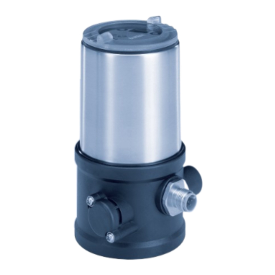
    Bild 1: Aufbau 1 4.2 Gewährleistung Der Positioner Typ 8696 ist ein elektropneumatischer Stellungsregler für pneumatisch betätigte Stellventile mit einfachwirkenden Antrieben. Voraussetzung für die Gewährleistung ist der bestimmungsgemäße Der Positioner bildet mit dem pneumatischen Antrieb eine optische Gebrauch des Positioners unter Beachtung der spezifizierten und funktionelle Einheit.
  • Seite 28: Variante Zur Ansteuerung Von Fremdgeräten

    5.2 Variante zur ansteuerung von Elektrischer Anschluss fremdgeräten (Rundsteckverbinder) Mit einer speziellen Variante kann der Positioner Typ 8696 an Fremd- geräte angebaut werden. Steuerluftanschlus (Beschriftung: 1) Diese Variante besitzt ein anderes pneumatisches Anschlussgehäuse, damit die Steuerluftanschlüsse extern angeschlossen werden können. Abluftanschluss (Beschriftung: 3)
  • Seite 29: Technische Daten

    „In Ruhestellung“ bedeutet, dass das Steuerventil des Positi- oners Typ 8696 stromlos bzw. nicht betätigt ist. 6.1 konformität Der Positioner Typ 8696 ist konform zu den EG-Richtlinien entspre- Bei feuchter Umgebungsluft kann eine Schlauchverbindung chend der EG-Konformitätserklärung. zwischen Steuerluftausgang 2 des Positioners und dem 6.2...
  • Seite 30: Mechanische Daten

    Typ 8696 TechnischeDaten 6.6 Typschilder Umgebungstemperatur siehe Typschild Schutzart 6.6.1 Typschild (Beispiel) Typ; für UL und ATEX geltende Merkmale des Vom Hersteller bewertet: Von UL bewertet: Typschlüssels Steuerfunktion; Steuerventil; IP65 / IP67 nach EN 60529 UL Type 4x Rating Versorgungsspannung 8696 -E1-...-0...
  • Seite 31: Pneumatische Daten

    Typ 8696 TechnischeDaten 6.7 pneumatische Daten 6.8 elektrische Daten Steuermedium neutrale Gase, Luft Warnung! Qualitätsklassen nach ISO 8573-1 Bei UL zugelassenen Komponenten dürfen nur Stromkreise Staubgehalt Klasse 7 max. Teilchengröße 40 µm, begrenzter Leistung nach „NEC Class 2“ verwendet werden. max. Teilchendichte 10 mg/m³...
  • Seite 32: Werkseinstellungen Des Positioners

    Typ 8696 Montage 6.9 Werkseinstellungen des positioners monTaGe Über DIP-Schalter aktivierbare Funktionen: Nur für Positioner ohne vormontiertes Prozessventil. funktion parameter Wert 7.1 sicherheitshinweise gefahr! CUTOFF Dichtschließfunktion unten Dichtschließfunktion oben 98 % Verletzungsgefahr durch hohen druck in anlage/Gerät. ▶ Vor Arbeiten an Anlage oder Gerät, den Druck abschalten und...
  • Seite 33: Montage Positioner An Prozessventile Der Reihe 2103 Und 23Xx

    Typ 8696 Montage → 7.2 montage positioner an prozessventile Den Positioner ohne Drehbewegung soweit auf den Antrieb schieben, dass an der Formdichtung kein Spalt mehr sichtbar ist. der reihe 2103 und 23xx hinWeiS! hinWeiS! Bei montage an prozessventile mit schweißgehäuse die mon- durch ein zu hohes drehmoment beim einschrauben der Befestigungsschraube kann die schutzart ip65 / ip67 nicht tagehinweise in der Bedienungsanleitung des prozessventils beachten. sichergestellt werden. ▶ Die Befestigungsschraube darf nur mit einem maximalen Dreh- Bei der Montage des Positioners dürfen die Collets der Steu-...
  • Seite 34: Pneumatische Installation

    Typ 8696 PneumatischeInstallation pneumaTische insTallaTion Wichtiger Hinweis zur einwandfreien Funktion des Geräts: ▶ Durch die Installation darf sich kein Rückdruck aufbauen. gefahr! ▶ Für den Anschluss einen Schlauch mit ausreichendem Querschnitt wählen. Verletzungsgefahr durch hohen druck in anlage/Gerät. ▶ Die Abluftleitung muss so konzipiert sein, dass kein Wasser ▶...
  • Seite 35: Elektrische Installation

    Typ 8696 ElektrischeInstallation 9.2 e lektrische installation mit elekTrische insTallaTion rundsteckverbinder Alle elektrischen Eingänge und Ausgänge des Geräts sind zur Versor- → Den Positioner entsprechend den Tabellen anschließen. gungsspannung nicht galvanisch getrennt. 9.1 sicherheitshinweise gefahr! Gefahr durch stromschlag. ▶ Vor Arbeiten an Anlage oder Gerät, die Spannung abschalten und...
  • Seite 36: Inbetriebnahme

    Typ 8696 Inbetriebnahme 10 inBeTrieBnahme Betriebsspannung ader- 10.1 sicherheitshinweise Belegung äußere Beschaltung farbe Warnung! grün 24 V DC ± 10 % max. Restwelligkeit Verletzungsgefahr bei unsachgemäßem Betrieb. 10 % gelb + 24 V Nicht sachgemäßer Betrieb kann zu Verletzungen, sowie Schäden am Gerät und seiner Umgebung führen.
  • Seite 37 Typ 8696 Inbetriebnahme hinWeiS! Taste 1 LED 2 durch einen falschen steuerdruck oder aufgeschalteten DIP-Schalter Betriebsdruck am Ventilsitz kann es zur fehlanpassung des LED 1 reglers kommen. Taste 2 ▶ X.TUNE in jedem fall bei dem im späteren Betrieb zur Ver- fügung stehenden Steuerdruck (= pneumatische Hilfsenergie) durchführen. Bild 11: Starten X.TUNE ▶ Die Funktion X.TUNE vorzugsweise ohne Betriebsmediumsdruck →...
  • Seite 38: Bedienung Und Anzeigeelemente

    Typ 8696 Inbetriebnahme → Gehäuse schließen (Schraubwerkzeug: 674078 Taste 1 LED 2 DIP-Schalter Das Schraubwerkzeug (674078) ist über Ihre Bürkert- LED 1 Vertriebsniederlassung erhältlich. Taste 2 Kommunikations- 10.3 Bedienung und anzeigeelemente schnittstelle Eine detaillierte Beschreibung der Bedienung und Funktionen des Positioners und der Kommunikationssoftware finden Sie Bild 13: Beschreibung Bedienelemente in der jeweiligen Bedienungsanleitung.
  • Seite 39: Betriebszustand

    Typ 8696 Inbetriebnahme 10.3.1 Betriebszustand 10.3.2 funktionen der Tasten Die Belegung der 2 Tasten sind je nach Betriebszustand (AUTOMATIK AUTOMATIK / HAND) unterschiedlich. Im Betriebszustand AUTOMATIK wird der normale Reglerbetrieb Taste 1 ausgeführt und überwacht. LED 1 blinkt grün. HAND Taste 2 Im Betriebszustand HAND kann das Ventil manuell über die Tasten...
  • Seite 40: Funktion Der Dip-Schalter

    Typ 8696 Inbetriebnahme 10.3.3 funktion der Dip-schalter 10.3.4 anzeige der leDs dip- LED 2 funktion schalter 1 2 3 4 LED 1 Umkehr der Wirkrichtung des Sollwerts (20 ... 4 mA entspricht 0 ... 100 %), fallend (DIR.CMD) normale Wirkrichtung des Sollwerts (4 ... 20 mA entspricht 0 ... 100 %), steigend Dichtschließfunktion aktiv.
  • Seite 41: Sicherheitsstellungen

    Typ 8696 Sicherheitsstellungen 11 sicherheiTssTellunGen led 1 (grün / rot) LED-Zustände Anzeige sicherheitsstellung nach grün ausfall der hilfsenergie Hochlaufphase bei Power ON antriebssart Bezeichnung pneuma- blinkt langsam Betriebszustand AUTO elektrisch tisch blinkt blinkt Betriebszustand HAND im Wechsel einfach- blinkt schnell X.TUNE Funktion wirkend nicht FEHLER (siehe down...
  • Seite 42: Zubehör

    Typ 8696 Zubehör 12 zuBehör 13 TransporT, laGerunG, VerpackunG Bezeichnung Bestell-nr. hinWeiS! USB-Adapter zum Anschluss eines PC in 227093 transportschäden. Verbindung mit einem Verlängerungskabel Unzureichend geschützte Geräte können durch den Transport Infos unter Communicator beschädigt werden. www.buerkert.de ▶ Gerät vor Nässe und Schmutz geschützt in einer stoßfesten Ver-...
  • Seite 43 7 montaGe ..................... 52 1 Quickstart ....................44 Consignes de sécurité ............52 Définition du terme / abréviation ..........44 Montage du positionneur type 8696 sur les vannes Symboles ...................44 process des séries 2103 et 23xx ........53 2 utilisation conforme ..............45 8 installation pneumatiQue ............54 Restrictions ................45...
  • Seite 44: Quickstart

    Vous trouverez la description détaillée de l’appareil dans le manuel ▶ Risque de blessures graves, voire la mort en cas de non-respect. d’utilisation du type 8696. remarque ! Vous trouverez le manuel d’utilisation sur le CD fourni ou bien sur Internet sous : met en garde contre des dommages matériels.
  • Seite 45: Utilisation Conforme

    ▶ Veillez à ce que l’utilisation du positionneur type 8696 soit toujours conforme. 2.1 restrictions Lors de l’exportation du système / de l’appareil, veuillez respecter les...
  • Seite 46 Type 8696 Consignesdesécuritéfondamentales ▶ Lors du vissage et du dévissage de l’enveloppe du corps ou du situations dangereuses d’ordre général. capot transparent ne pas exercer de contre pression sur l’action- Pour prévenir les blessures, respectez ce qui suit : neur de la vanne process mais sur le corps de raccordement du ▶...
  • Seite 47: Indications Générales

    Structure 1 La condition pour bénéficier de la garantie légale est l’utilisation Le positionneur type 8696 est un régulateur de position électropneu- conforme du positionneur type 8696 dans le respect des conditions matique pour vannes de régulation à commande pneumatique avec d’utilisation spécifiées.
  • Seite 48: Variante De Commande Des Appareils Étrangers

    Type 8696 DescriptionduSystème 5.2 Variante de commande des Raccordement électrique appareils étrangers (connecteur rond) Une variante spéciale permet de monter le positionneur type 8690 sur les appareils étrangers. Raccord d’air de pilotage Cette variante est dotée d’un autre corps de raccordement pneuma- (Légende : 1) tique permettant le raccordement externe des raccords d’air de pilotage...
  • Seite 49: Caractéristiques Techniques

    8696 ne sont pas alimentées en courant ou 6.1 conformité ne sont pas activées. Le positionneur type 8696 est conforme aux directives CE sur la base de la déclaration de conformité CE. Avec un air ambiant humide, il est possible de réaliser pour 6.2...
  • Seite 50: Caractéristiques Mécaniques

    Type 8696 Caractéristiquestechniques 6.6 plaque singnalétique Température ambiante voir plaque signalétique Degré de protection 6.6.1 plaque signalétique (exemple) Type; caractéristiques du code type applicables à Évalué par le fabricant : Évalué par UL : UL et ATEX IP65 / IP67 selon EN 60529 Classification UL type 4x Fonction;...
  • Seite 51: Caractéristiques Pneumatiques

    Type 8696 Caractéristiquestechniques 6.7 caractéristiques pneumatiques 6.8 caractéristiques électriques Fluide de commande gaz neutres, air aVertiSSement ! Classes de qualité selon ISO 8573-1 Dans le cas des composants à homologation UL, seuls des cir- Teneur en poussières Classe 7 Taille maximale des particules cuits électriques à...
  • Seite 52: Réglages Usine Du Positionneur

    Tab. 2 : Réglages usine - Fonctions aVertiSSement ! Des autres fonctions sont décrites dans le manuel d’utili- sation du type 8696. risque de blessures dû à un montage non conforme. ▶ Le montage doit être effectué uniquement par un personnel quali- Vous trouverez ce manuel sur Internet sous fié...
  • Seite 53: Montage Du Positionneur Type 8696 Sur Les Vannes Process Des Séries 2103 Et 23Xx

    Type 8696 Montage → 7.2 montage du positionneur type 8696 Glisser le positionneur sur l’actionneur sans la faire tourner jusqu’à ce que le joint profilé ne présente plus d’interstice. sur les vannes process des séries 2103 et 23xx remarque ! remarque ! le type de protection ip65 / ip67 ne peut être garanti si le lors du montage sur les vannes process à corps soudé, observer couple de serrage de la vis de fixation est trop élevé. les consignes de montage dans le manuel d‘utilisation de la ▶...
  • Seite 54: Installation Pneumatique

    Type 8696 Installationpneumatique insTallaTion pneumaTiQue Maintenez la pression d’alimentation appliquée absolument à au moins 0,5 ... 1 bar au-dessus de la pression nécessaire pour Danger ! amener l’actionneur dans sa position finale. De cette façon, vous avez la garantie que le comportement de régulation dans risque de blessures dû à la présence de haute pression dans...
  • Seite 55: Installation Électrique

    Type 8696 Installationélectrique insTallaTion élecTriQue Toutes les sorties et entrées de l’appareil ne sont pas à séparation galvanique pour la tension d’alimentation. 9.1 consignes de sécurité Danger ! Fig. 9 : Connecteur rond M12 x 1, 8-pôles risque de choc électrique. ▶ Avant de travailler sur l’installation ou l’appareil, couper la tension et empêcher toute remise sous tension par inadvertance.
  • Seite 56: Mise En Service

    Type 8696 Miseenservice tension de service 10 mise en serVice couleur 10.1 consignes de sécurité Broche affectation câblage externe de fil aVertiSSement ! vert 24 V DC ± 10 % ondulation rési- risque de blessures dû à un montage non conforme. duelle maxi 10 % jaune + 24 V Une utilisation non conforme peut entraîner des blessures et Tab.
  • Seite 57 Type 8696 Miseenservice → Pour commander les touches et les interrupteurs DIP, dévisser le remarque ! capot transparent. evitez une mauvaise adaptation du régulateur suite à une Touche 1 pression de pilotage ou une pression de fluide de service erronée. LED 2 ▶ Exécutez dans tous les cas X.TUNE avec la pression de pilotage Interrupteur DIP disponible lors du fonctionnement ultérieur (= énergie auxiliaire...
  • Seite 58: Eléments De Commande Et D'affichage

    Type 8696 Miseenservice 10.3 e léments de commande et remarque ! d’affichage rupture des manchons pneumatiques due à la torsion. Une description détaillée de la commande et des fonctions ▶ Pour dévisser et visser le capot transparent, ne pas exercer de du positionneur et du logiciel de communication est décrite contre pression sur l’actionneur de vanne process mais sur le...
  • Seite 59: Etat De Marche

    Type 8696 Miseenservice 10.3.1 etat de marche Touche 1 LED 2 AUTOMATIQUE (AUTO) Interrupteurs DIP A l’état de marche AUTOMATIQUE, le fonctionnement normal du LED 1 régulateur est effectué et surveillé. Touche 2 La LED 1 clignote en vert. Interface de communication MANUEL (MANU) A l’état de marche MANUEL, la vanne peut être ouverte ou fermée...
  • Seite 60: Fonction Des Interrupteurs Dip

    Type 8696 Miseenservice 10.3.3 fonction des interrupteurs Dip Touche 1 interrup- fonction Touche 2 teurs dip 1 2 3 4 Inversion du sens d’action de la valeur de consigne Fig. 14 : Touches (la valeur de consigne 20 ... 4 mA correspond à la Etat de marche MANUEL (interrupteur DIP 4 sur ON) : position 0 ...
  • Seite 61: Affichage Des Led

    Type 8696 Miseenservice 10.3.4 affichage des leD led 1 (vert / rouge) etats des LeD affichage vert rouge LED 2 allumée éteinte Phase de démarrage pour Power ON LED 1 clignote éteinte Etat de marche AUTO (AUTOMATIQUE) lentement clignote clignote Etat de marche MANUEL en alternance clignote éteinte...
  • Seite 62: Positions De Sécurité

    Type 8696 Positionsdesécurité led 2 (vert / jaune) 11 posiTions De sécuriTé etats des LeD affichage réglages de sécurité vert jaune après une panne de allumée éteinte actionneur fermé type l’énergie auxiliaire désignation d’actionneur pneuma- éteinte allumée actionneur ouvert électrique tique clignote Écart de régulation permanent éteinte lentement (valeur effective > valeur de consigne) clignote Écart de régulation permanent...
  • Seite 63: Accessoires

    Type 8696 Accessoires 12 accessoires 12.3 Téléchargement Téléchargement du logiciel sous : www.buerkert.fr n° de désignation commande Adaptateur USB pour le raccordement d'un 227093 PC en liaison avec un câble de rallonge Infos sous Communicator www.buerkert.fr Câble de raccordement M12 x1, 8 pôles...
  • Seite 64: Emballage, Transport, Stockage

    Type 8696 Emballage,transport,stockage 13 emBallaGe, TransporT, sTockaGe remarque ! dommages dus au transport. Les appareils insuffisamment protégés peuvent être endommagés pendant le transport. ▶ Transportez l'appareil à l'abri de l'humidité et des impuretés et dans un emballage résistant aux chocs. ▶ Évitez le dépassement vers le haut ou le bas de la température de stockage admissible.
  • Seite 66 www.burkert.com...

Inhaltsverzeichnis