Werbung
Verfügbare Sprachen
Verfügbare Sprachen
Quicklinks
Werbung

Verwandte Anleitungen für Balluff BFD 3SAP-19N000-U01-LA2-C Serie


Inhaltszusammenfassung für Balluff BFD 3SAP-19N000-U01-LA2-C Serie
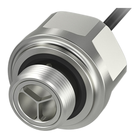
- Seite 1 BFD 3SAP-19N000-U01-LA2-C_ _ _ _ _ deutsch Konfigurationsanleitung english Configuration Guide...
- Seite 2 www.balluff.com...
- Seite 3 BFD 3SAP-19N000-U01-LA2-C_ _ _ _ _ Konfigurationsanleitung deutsch...
- Seite 4 www.balluff.com...
- Seite 5 Sekundäre Gerätefunktionen Signalverzögerung (Signal Delay) Signalgeschwindigkeitsüberwachung (Signal Speed Monitor) Schaltzähler (Switching Counter) Grundlegende Statistik (Basic Statistics) Logische Blöcke (Logic Blocks) Betriebsstundenzähler (Operating Hours Counter) Betriebsstartzähler (Boot Cycle Counter) Spannungs- und Stromüberwachung (Voltage and Current Monitoring) Interne Temperatur (Internal Temperature) www.balluff.com deutsch...
- Seite 6 BFD 3SAP-19N000-U01-LA2-C_ _ _ _ _ Ultraschall-Sensoren Systemfunktionen Gerätestatus und detailierter Gerätestatus (Device Status and Detailed Device Status) Diagnoseunterdrückung (Diagnosis Suppression) Resetbefehle (Reset Commands) Variantenkonfiguration (Variant Configuration) Pinzuweisung (Pin Assignment) Bedeutung der LED-Zustände und Konfiguration (LED Meaning and Configuration) Prozessdateninformation und -konfiguration (Process Data Info and Configuration) Profilcharakteristik (Profile Characteristic) Parametermanager (Parameter Manager)
- Seite 7 BFD 3SAP-19N000-U01-LA2-C_ _ _ _ _ Ultraschall-Sensoren Zu dieser Anleitung Gültigkeit Verwendete Fachbegriffe und Abkürzungen Diese Anleitung stellt umfangreiche Informationen bereit BMSP Balluff Measurement Sensor Profile zur IO-Link-Konfiguration folgender Produkte: CCM Comprehensive Condition Monitoring – BFD 3SAP-19N000-U01-LA2-C30S04 IODD IO-Device-Description Bestellcode: BFD0002 –...
- Seite 8 BFD 3SAP-19N000-U01-LA2-C_ _ _ _ _ Ultraschall-Sensoren Basiswissen IO-Link Allgemein Prozessdatenstrom IO-Link integriert konventionelle und intelligente Sensoren Die Datenübertragung basiert auf der allgemeinen Profil- und Aktoren in Automatisierungssysteme und ist als spezifikation (IO-Link Common Profile 1.0, Beispiel siehe Kommunikationsstandard unterhalb der klassischen Feld- Bild 2-1).
- Seite 9 Das System aus Master und Device stellt so einen Geräteaustausch ohne die Notwendigkeit einer aktiven Umparametrierung sicher. Die Einstellungen bezüglich Data Storage sind auf dem IO-Link Master Gateway vorzunehmen (entnehmen Sie die Informationen der entsprechenden Dokumentation). www.balluff.com deutsch...
- Seite 10 BFD 3SAP-19N000-U01-LA2-C_ _ _ _ _ Ultraschall-Sensoren Übersicht IO-Link-Daten und -Funktionen Übersicht der enthaltenen Funktionen 3.1.1 Primäre Funktionen – Identifikation (Identification) siehe Seite 25 – Geräteerkennung (Device Discovery) siehe Seite 26 – Schaltprofile (Switching Profiles) siehe Seite 27 – Messprofile (Measurement Profiles) siehe Seite 35 –...
- Seite 11 Baudrate PDInput PDOutput IO-Link- Minimale Protokoll version Zykluszeit Smart Sensor Profil Ed. 2 0x030501 COM3 6 Byte 0 Byte V1.1 1,4 ms (BMSP) (230,4 kBaud) Comprehensive Condition 0x030503 COM3 10 Byte 0 Byte V1.1 1,4 ms Monitoring (CCM) (230,4 kBaud) Tab. 3-1: Gerätevarianten – wählbare Profile www.balluff.com deutsch...
- Seite 12 BFD 3SAP-19N000-U01-LA2-C_ _ _ _ _ Ultraschall-Sensoren Übersicht IO-Link-Daten und -Funktionen (Fortsetzung) Prozessdatenprofile Prozessdateninformation und -konfiguration (Process Data Info and Configuration) siehe Kapitel 7.7 auf Seite 83. 3.3.1 Smart Sensor Profile Ed. 2 (BMSP) PDInput Byte 0 Bit 7 Bit 6 Bit 5 Bit 4 Bit 3 Bit 2 Bit 1 Bit 0 Byte 1...
- Seite 13 Bit 6 Bit 5 Bit 4 Bit 3 Bit 2 Bit 1 Bit 0 Position Byte 4…7 Bit 7 Bit 6 Bit 5 Bit 4 Bit 3 Bit 2 Bit 1 Bit 0 Temperature Byte 8 Bit 7 Bit 6 Bit 5 Bit 4 Bit 3 Bit 2 Bit 1 Bit 0 Signal Quality Byte 9 Bit 7 Bit 6 Bit 5 Bit 4 Bit 3 Bit 2 Bit 1 Bit 0 www.balluff.com deutsch...
- Seite 14 (BMSP + analog)" Product ID 0x0013 […] STRING z. B. "BFD 3SAP- (19) 19N000-U01- LA2-CA2000 (BMSP + analog)" Product Text 0x0014 […] STRING z. B. "Balluff Fluid (20) Sensor Distance" Serial Number 0x0015 16 Byte STRING (21) Hardware Revision 0x0016 2 Byte STRING (22) Firmware Revision 0x0017 ≤ 10 Byte...
- Seite 15 Setpoint 2 4 Byte INT32 Nein 0x7FFF FFFC (deaktiviert) SSC 4 Configuration 0x4003 4 Byte (16387) Switchpoint Logic 1 Byte UINT8 Nein 0x00 Switchpoint Mode 1 Byte UINT8 Nein 0x01 Switchpoint Hysteresis 2 Byte INT16 Nein 0x96 Transducer Value 0x01B2 4 Byte INT32 (434) www.balluff.com deutsch...
- Seite 16 BFD 3SAP-19N000-U01-LA2-C_ _ _ _ _ Ultraschall-Sensoren Übersicht IO-Link-Daten und -Funktionen (Fortsetzung) Name Index Sub- Zugriff Länge Datentyp Data Default index Storage Messprofile MDC Descriptor 0x4080 11 Byte (16512) Lower Limit 4 Byte INT32 Upper Limit 4 Byte INT32 Max. Länge Unit Code 2 Byte UINT16(ENUM) 1010 (m)
- Seite 17 Speed Upper Limit 2 Byte UINT16 Nein Speed Lower Limit 2 Byte UINT16 Nein High Speed Lower Limit 2 Byte UINT16 Nein Startup Delay 1 Byte UINT8 Nein Switching Speed 0x009C 3 Byte Status (156) State 1 Byte UINT8(ENUM) – Value 2 Byte UINT16 – www.balluff.com deutsch...
- Seite 18 BFD 3SAP-19N000-U01-LA2-C_ _ _ _ _ Ultraschall-Sensoren Übersicht IO-Link-Daten und -Funktionen (Fortsetzung) Name Index Sub- Zugriff Länge Datentyp Data Default index Storage Schaltzähler Switching Counter 0x00B6 6 Byte (182) Input 2 Byte UINT16(ENUM) Nein Mode 1 Byte UINT8(ENUM) Nein Limit 2 Byte UINT16 Nein Startup Delay 1 Byte UINT8...
- Seite 19 Logic Block 4 Result 1 Byte BOOL Betriebsstundenzähler Operating Hours 0x0057 12 Byte Counter (87) Current Operating 4 Byte UINT32 – Hours Total Operating Hours 4 Byte UINT32 – Custom Operating 4 Byte UINT32 – Hours Operating Hours 0x0074 1 Byte UINT8(ENUM) Saving Mode (116) www.balluff.com deutsch...
- Seite 20 BFD 3SAP-19N000-U01-LA2-C_ _ _ _ _ Ultraschall-Sensoren Übersicht IO-Link-Daten und -Funktionen (Fortsetzung) Name Index Sub- Zugriff Länge Datentyp Data Default index Storage Betriebsstartzähler Boot Cycle Counter 0x0058 8 Byte (88) Boot Cycle Counter 4 Byte UINT32 – Custom Boot Cycle 4 Byte UINT32 –...
- Seite 21 Nein 0 (Rising) Type 1 Byte UINT8(ENUM) Nein 0 (4…20 mA) Bedeutung der LED-Zustände und Konfiguration LED Standard 0x00FD 1 Byte UINT8(ENUM) 0 (Balluff) Selection (253) Prozessdateninformation und -konfiguration Process Data Profile 0x0051 1 Byte UINT8(ENUM) 1 (Smart Sensor selection (81) Profile Ed. 2)
- Seite 22 BFD 3SAP-19N000-U01-LA2-C_ _ _ _ _ Ultraschall-Sensoren Übersicht IO-Link-Daten und -Funktionen (Fortsetzung) Name Index Sub- Zugriff Länge Datentyp Data Default index Storage Profilcharakteristik Profile Characteristic 0x000D 10 Byte UINT16[ ] – (13) Gerätezugriffssperren Device Access Locks 0x000C 2 Byte UINT16 (12) Tab. 3-2: ISDU –...
- Seite 23 Teach Preset – Setzt den aktuellen Messwert auf den Wert von Measurement Preset. 0xE1 (225) Teach Lower Limit – Setzt das untere Ende des Messbereichs. 0xE2 (226) Teach Upper Limit – Setzt das obere Ende des Messbereichs. Tab. 3-3: System Commands – Übersicht www.balluff.com deutsch...
- Seite 24 BFD 3SAP-19N000-U01-LA2-C_ _ _ _ _ Ultraschall-Sensoren Übersicht IO-Link-Daten und -Funktionen (Fortsetzung) Events Event-Code Event-Typ Event – Beschreibung – Abhilfe Device Status 0x1850 Benachrichtigung Process Data Profilauswahl nicht anwendbar – Stan- 0 – Device is operating properly. (6224) dardwert wird verwendet. 0x1851 Benachrichtigung Process Data Update Timeout –...
- Seite 25 1 - Maintenance required (36134) zurückgesetzt. ► Einstellungen prüfen und Warnung bestätigen. 0x8DC0 Benachrichtigung Teach-in Timeout – Der aktuelle Teachvorgang 0 – Device is operating properly. (36288) dauerte zu lange und wurde abgebrochen. Tab. 3-4: Events – Übersicht www.balluff.com deutsch...
- Seite 26 BFD 3SAP-19N000-U01-LA2-C_ _ _ _ _ Ultraschall-Sensoren Kommunikationsparameter In Tab. 4-1 ist die grundlegende IO-Link-Spezifikation der Standardvariante BFD 3SAP-19N000-U01-LA2-C... (BMSP) beschrieben. Spezifikation IO-Link-Bezeichnung Wert Übertragungsrate COM3 (230,4 kBaud) Minimale Zykluszeit Device min cycle time 0×0E (1,4 ms) Frame-Spezifikation: M-Sequence Capability: 0×1B – Anzahl Bedarfsdaten Preoperate –...
- Seite 27 Application Specific Tag Product Type Code Mit dem Parameter Application Specific Tag kann ein Der Balluff Typenschlüssel ist fest im Gerät hinterlegt. String (maximal 32 Byte) in das Device geschrieben wer- den. Typischerweise beschreibt dieser Wert die Applika- Product Order Code tion, in der das Produkt eingesetzt wird.
- Seite 28 BFD 3SAP-19N000-U01-LA2-C_ _ _ _ _ Ultraschall-Sensoren Primäre Gerätefunktionen (Fortsetzung) Geräteerkennung (Device Discovery) 5.2.1 Beschreibung Mit der Funktion Device Discovery kann ein IO-Link-Device wiedergefunden werden, indem per System Command eine Signalisierung an der LED vom Device gestartet wird. 5.2.2 ISDU Name Index Subindex...
- Seite 29 Voraussetzungen und Regeln, die für die Teach-Verfahren gelten. Über die Setpoint-Einstellung ist es zusätzlich möglich, die Schaltpunktauswertung zu deaktivieren. Hierzu wird der Einstellwert No Measurement Data (Kein Messwert) ver- wendet: Status Wert No Measurement 2.147.483.644 (0x7FFFFFFC) Data (32 Bit) Tab. 5-4: Schaltprofile – Schaltpunktauswertung deaktivieren www.balluff.com deutsch...
- Seite 30 Folgende Teach-Kommandos sind jeweils für Set- Bild 5-3: Einzelpunktmodus point 1 und Setpoint 2 verfügbar: Single Value Teach, Two Value Teach und Dynamic Teach (Profile Spec. und Balluff Spec.). Two Point Mode Im Zweipunktmodus (Two Point Mode) werden zwei Schaltpunktlogik (Switchpoint logic) Schaltpunkte (Setpoints) definiert.
- Seite 31 Apply-Befehl abgeschlossen, dies ist nur möglich Bild 5-10: Dynamic Teach im Single Point Mode wenn jeweils beide Anlernpunkte angelernt wurden. Alter- nativ kann der Anlernvorgang auch durch einen Cancel- Befehl abgebrochen werden. Alle unvollständigen Anlern- punktpaare gehen hierbei verloren. www.balluff.com deutsch...
- Seite 32 1. Dynamic Teach SP2 Start 2. Dynamic Teach SP1 Stop erfasste Messwerte Bild 5-12: Dynamic Teach (Balluff) (Two Point Mode) Manual Teach-in Zusätzlich zu den IO-Link-gesteuerten Teach-Verfahren gibt es die Möglichkeit eines manuellen Teach-in. Dabei handelt es prinzipiell um einen Single Value Teach des Setpoint 1 im Single Point Schaltmodus.
- Seite 33 LSSC Switching Signal Channel 2 Eingang 0x003C (60) LSSC 3 LSSC Switching Signal Channel 3 Eingang 0x003D (61) LSSC 4 LSSC Switching Signal Channel 4 Eingang 0x003E (62) Teach-in Manual Teach-in Trigger Ausgang Tab. 5-5: Schaltprofile – Process Data www.balluff.com deutsch...
- Seite 34 BFD 3SAP-19N000-U01-LA2-C_ _ _ _ _ Ultraschall-Sensoren Primäre Gerätefunktionen (Fortsetzung) 5.3.3 ISDU [LSSC] Name Index Sub- Zugriff Länge Datentyp Data Default index Storage Teach-in Select 0x003A (58) 1 Byte UINT8 Nein 0x00 Teach-in Result 0x003B (59) 1 Byte UINT8 – SSC 1 Parameter 0x003C (60) 8 Byte Setpoint 1...
- Seite 35 SP2 war erfolgreich. 4 = WAIT FOR COMMAND – Warte auf nächstes Kommando. 5 = BUSY – Vorgang aktiv 6 = Reserviert 7 = ERROR – Letzter Vor- gang war nicht erfolg- reich. Tab. 5-9: Schaltprofile – Teach-in Result www.balluff.com deutsch...
- Seite 36 BFD 3SAP-19N000-U01-LA2-C_ _ _ _ _ Ultraschall-Sensoren Primäre Gerätefunktionen (Fortsetzung) SSC X Configuration 5.3.4 System Commands Dieser ISDU dient zum Konfigurieren des SSC. Es kann die Command-Wert Geräteaktion Schaltlogik, Schaltmodus sowie die Hysterese eingestellt 0x40 (64) Teach Apply – Berechnet den werden.
- Seite 37 Außerhalb des Messbereichs ist eine Messwertausgabe in den nichtlinearen Bereichen (Limited Accuracy Areas) noch möglich, die Genauigkeit kann für diese Bereiche aber nicht mehr zugesichert werden. Über die Prozessdaten wird durch das Bit Measurement Warning angezeigt, dass die Genauigkeit limitiert ist. www.balluff.com deutsch...
- Seite 38 BFD 3SAP-19N000-U01-LA2-C_ _ _ _ _ Ultraschall-Sensoren Primäre Gerätefunktionen (Fortsetzung) 5.4.2 Process Data Object ID Name Beschreibung Richtung 0x0028 (40) Measurement Value Measurement Value enthält den Messwert. Eingang 0x002A (42) Measurement Value Scale Die Skalierung als Exponent einer Zehnerpotenz Eingang 0x002B (43) Measurement Error Messwert außerhalb des Erfassungsbereichs oder kein Messwert...
- Seite 39 (194) Measurement 0x00C3 1 Byte BOOL Output (195) Characteristics Measurement 0x00C4 4 Byte UINT32 Hysteresis (196) Measurement 0x0202 8 Byte Range (514) Lower Limit 4 Byte INT32 Nein 0x8000 0300 Upper Limit 4 Byte INT32 Nein 0x7FFF FD00 Tab. 5-18: Messprofile – ISDU www.balluff.com deutsch...
- Seite 40 BFD 3SAP-19N000-U01-LA2-C_ _ _ _ _ Ultraschall-Sensoren Primäre Gerätefunktionen (Fortsetzung) MDC Descriptor Measurement Preset Der MDC Descriptor enthält informationen über den aktuel- Der Measurement Preset kann verwendet werden, um len Wertebereich des Messwerts (Measurement Value) einen Measurmeent Offset zu berechnen. Measurement innerhalb der Grenzen des Messbereichs (Measurement Preset gibt einen Zielwert an, der nach einem Teach Preset Range), über die Einheit und Skalierung des Messwerts.
- Seite 41 Es kann kein Messwert ermittelt werden. 2 – Out of Specification ► Applikation prüfen. 0x8D05 (36101) Warnung Messfehler/Redundanzprüfung fehlgeschlagen. 2 – Out of Specification ► Applikation prüfen. Tab. 5-23: Messprofile – Events 5.4.7 Variantenabhängigkeit Die Funktionalität ist in allen Varianten verfügbar. www.balluff.com deutsch...
- Seite 42 BFD 3SAP-19N000-U01-LA2-C_ _ _ _ _ Ultraschall-Sensoren Primäre Gerätefunktionen (Fortsetzung) Signalqualität (Signal Quality) 5.5.1 Beschreibung Die Signalqualität wird in Prozentschritten als Wert zwi- Zusätzlich bietet die Überwachung der Signalqualität eine schen 0 und 100 % angegeben. Wenn die Signalqualität sofortige Reaktion im Falle eines kritischen Ausfalls. Diese nicht bereitgestellt werden kann, wird ein Ersatzwert von Reaktion wird ausgelöst, wenn die Signalqualität unter 0xFF (255) ausgegeben.
- Seite 43 Wenn der Wert TRUE ist, liegt die Signalqualität unter dem Schwellenwert, wenn der Wert FALSE ist, ist die Signalqualität gleich oder über dem Schwellenwert. Dieser Status wird durch eine orange LED visualisiert, die auf- leuchtet, wenn der Wert TRUE ist. www.balluff.com deutsch...
- Seite 44 BFD 3SAP-19N000-U01-LA2-C_ _ _ _ _ Ultraschall-Sensoren Primäre Gerätefunktionen (Fortsetzung) 5.5.5 System Commands Command- Geräteaktion Wert 0x81 (129) Application Reset – Setzt den Schwel- lenwert mit ISDU Index 0xCE Low Signal Quality Threshold auf Default 0 zurück. Dadurch ist das Feature deaktiviert und die Evaluation auf dem Index 0xCF Subindex 2 ergibt immer FALSE.
- Seite 45 Ausgangssignal Signal Delay Channel 1 Eingang 0x0009 (9) Signal Delay Channel 2 Ausgangssignal Signal Delay Channel 2 Eingang 0x000A (10) Signal Delay Channel 3 Ausgangssignal Signal Delay Channel 3 Eingang 0x000B (11) Signal Delay Channel 4 Ausgangssignal Signal Delay Channel 4 Eingang Tab. 6-1: Signalverzögerung – Process Data www.balluff.com deutsch...
- Seite 46 BFD 3SAP-19N000-U01-LA2-C_ _ _ _ _ Ultraschall-Sensoren Sekundäre Gerätefunktionen (Fortsetzung) 6.1.4 ISDU Name Index Subindex Zugriff Länge Datentyp Data Storage Default Signal Delay Input 0x0096 (150) 8 Byte Channel 1 2 Byte UINT16(ENUM) Nein Channel 2 2 Byte UINT16(ENUM) Nein Channel 3 2 Byte UINT16(ENUM) Nein Channel 4...
- Seite 47 One-Shot Ausgangssignal von Signal 0x0066 (102) Logic Block 4 Result Delay = 1/TRUE und One- Tab. 6-3: Signalverzögerung – Signal Delay Input Shot-Funktion läuft gerade. 0xFF (255) Deactivated Feature ist deaktiviert. Tab. 6-5: Signalverzögerung – Signal Delay Status www.balluff.com deutsch...
- Seite 48 BFD 3SAP-19N000-U01-LA2-C_ _ _ _ _ Ultraschall-Sensoren Sekundäre Gerätefunktionen (Fortsetzung) 6.1.5 System Commands Command- Geräteaktion Wert 0x81 (129) Application Reset – Setzt beschreibbare Parameter auf den Defaultwert zurück. 0x82 (130) Restore Factory Settings – Setzt beschreibbare Parameter auf den Defaultwert zurück. Tab.
- Seite 49 Eingang 0x0012 (18) Switching Speed Too High Switching Speed Value überhalb der Grenze Eingang 0x0013 (19) Switching Speed Value Switching Speed Value Eingang 0x0014 (20) Switching Speed Reset Reset Switching Speed Ausgang Tab. 6-7: Signalgeschwindigkeitsüberwachung – Process Data www.balluff.com deutsch...
- Seite 50 BFD 3SAP-19N000-U01-LA2-C_ _ _ _ _ Ultraschall-Sensoren Sekundäre Gerätefunktionen (Fortsetzung) 6.2.4 ISDU Name Index Sub- Zugriff Länge Datentyp Data Default index Storage Switching Speed Monitoring 0x009B (155) 12 Byte Input 2 Byte UINT16(ENUM) Nein Mode 1 Byte UINT8(ENUM) Nein Speed Upper Limit High 2 Byte UINT16 Nein...
- Seite 51 Overload Pin 4 0x0044 (68) Overload Pin 2 0x0063 (99) Logic Block 1 Result 0x0064 (100) Logic Block 2 Result 0x0065 (101) Logic Block 3 Result 0x0066 (102) Logic Block 4 Result Tab. 6-9: Signalgeschwindigkeitsüberwachung – Switching Speed Monitoring Input www.balluff.com deutsch...
- Seite 52 BFD 3SAP-19N000-U01-LA2-C_ _ _ _ _ Ultraschall-Sensoren Sekundäre Gerätefunktionen (Fortsetzung) Speed Monitoring State Mit Speed Monitoring State kann der aktuelle Status abgelesen werden. Wert Bedeutung Beschreibung 0x00 (0) Idle Es liegt noch kein Geschwin- digkeitswert vor 0x01 (1) Too low Geschwindigkeitswert ist kleiner als untere Schwelle 0x02 (2)
- Seite 53 Zählerzustandsflag reached gesetzt. Ist der Zählwert größer als die konfigurierte Zählergrenze, wird das Zählerzustandsflag exceeded gesetzt. Der Zählwert kann jederzeit durch ein System Command zurückgesetzt werden (Zählwert = Null). Bild 6-3: Schaltzähler – Static Mode www.balluff.com deutsch...
- Seite 54 BFD 3SAP-19N000-U01-LA2-C_ _ _ _ _ Ultraschall-Sensoren Sekundäre Gerätefunktionen (Fortsetzung) Switching Counter – Auto Mode Bei jeder steigenden Flanke des Eingangssignals wird der Zählerwert erhöht (siehe Bild 6-4). Ist der Zählerwert kleiner als die konfigurierte Zählergrenze, wird das Zählerzustandsflag not reached gesetzt. Sobald der Zählwert größer oder gleich der konfigurierten Zähler- grenze ist, wird das Zählerzustandsflag reached gesetzt.
- Seite 55 0x00B6 (182) 6 Byte Input 2 Byte UINT16(ENUM) Nein Mode 1 Byte UINT8(ENUM) Nein Limit 2 Byte UINT16 Nein Startup Delay 1 Byte UINT8 Nein Switching Counter Status 0x00B7 (183) 3 Byte State 1 Byte UINT8(ENUM) – Value 2 Byte UINT16 – Tab. 6-15: Schaltzähler – ISDU www.balluff.com deutsch...
- Seite 56 BFD 3SAP-19N000-U01-LA2-C_ _ _ _ _ Ultraschall-Sensoren Sekundäre Gerätefunktionen (Fortsetzung) Switching Counter Input Mit Switching Counter Input kann die interne binäre Signal- quelle ausgewählt werden. Input enthält eine Liste der internen binären Signale. Wert Name 0x0001 (1) Digital Input Pin 4 0x0002 (2) Digital Input Pin 2 0x0003 (3)
- Seite 57 Value ist größer als Limit. 0x08 (8) Startup Anlaufverzögerung läuft gerade. Delay 0xFF Deactivated Feature ist deaktiviert. (255) Tab. 6-18: Schaltzähler – Switching Counter State Switching Counter Value Mit Switching Counter Value kann der aktuelle Zählerwert abgelesen werden. www.balluff.com deutsch...
- Seite 58 BFD 3SAP-19N000-U01-LA2-C_ _ _ _ _ Ultraschall-Sensoren Sekundäre Gerätefunktionen (Fortsetzung) Grundlegende Statistik (Basic Statistics) 6.4.1 Beschreibung Mit der Funktion Basic Statistics können Statistikvorgänge ausgeführt werden, wie z. B. die Berechnung von Mini- mum, Maximum und Durchschnitt. Darüber hinaus ist es möglich, den gleitenden Durchschnitt zu berechnen. Mit Basic Statistics können Trends für die gewählte Ein- gabe über die angegebene Dauer (zwischen 1 Sekunde und 1 Woche oder 1 bis 1000 Abtastpunkte) anzeigt...
- Seite 59 Eingang 0x0056 (86) Moving Average Wiederholt berechneter Durchschnittswert Eingang 0x0057 (87) Status Statuswert Eingang 0x0058 (88) Number Of Samples Anzahl der Messwerte für die Berechnung von Minimum, Maximum und Eingang Durchschnitt Tab. 6-20: Grundlegende Statistik – Process Data www.balluff.com deutsch...
- Seite 60 BFD 3SAP-19N000-U01-LA2-C_ _ _ _ _ Ultraschall-Sensoren Sekundäre Gerätefunktionen (Fortsetzung) 6.4.4 ISDU Minimum, Maximum, Average and Moving Average outputs werden im FLOAT32-Format ausgegeben. Bevor sie weiterverarbeitet werden und von FLOAT32 zu INT32 oder UINT32 kon- vertiert werden, muss das Ausgangssignal geprüft werden, ob es größer als INT32_Max oder UINT32_Max ist.
- Seite 61 Durchschnitt für jeweils 100 Messwerte zu berechnen, kann als Einheit Messwerte (samples) gewählt werden. Wert Bedeutung Beschreibung 0x01 (1) Seconds Sekunden 0x02 (2) Minutes Minuten 0x03 (3) Hours Stunden 0x04 (4) Samples Messwerte Tab. 6-24: Statistics Data Configuration – Moving Average Window Unit www.balluff.com deutsch...
- Seite 62 BFD 3SAP-19N000-U01-LA2-C_ _ _ _ _ Ultraschall-Sensoren Sekundäre Gerätefunktionen (Fortsetzung) Statistics Data Output: Status Bit- Bedeutung Beschreibung position Configured 1 – alle Eingänge sind konfiguriert Started Min/ 1 – Min/Max/Avg läuft Max/Avg Started Moving 1 – Moving Average läuft Average Buffer Overflow 1 –...
- Seite 63 Es meldet keine Zeitüberschreitung für die Berechnung des gleitenden Durchschnitts, da sich der Zeitablauf des gleitenden Durchschnitts wiederholt und es nicht das Ende der Berechnung anzeigt. Tab. 6-28: Grundlegende Statistik – Events 6.4.7 Variantenabhängigkeit Die Funktionalität ist in allen Varianten verfügbar. www.balluff.com deutsch...
- Seite 64 BFD 3SAP-19N000-U01-LA2-C_ _ _ _ _ Ultraschall-Sensoren Sekundäre Gerätefunktionen (Fortsetzung) Logische Blöcke (Logic Blocks) Die Zykluszeit beträgt 1,4 ms. 6.5.1 Beschreibung Das Gerät bietet 4 digitale Logikblöcke, die als AND/NOR/ OR/XOR konfiguriert werden können. Jeder dieser Logik- blöcke hat 4 Eingangssignale. Diese Eingangssignale werden zyklisch entsprechend der Zykluszeit ausgewertet.
- Seite 65 Index: 0x79 Subindex: 3 Subindex: 4 MODE CONFIG MODE CONFIG AND/OR/NOR/XOR AND/OR/NOR/XOR Index: 0075 Index: 0075 Subindex: 3 Subindex: 4 Bild 6-8: Logische Blöcke – Mode Inputs 6.5.4 Mathematik/Algorithmus Wahrheitstabellen der Logic-Blocks-Modi Tab. 6-30: Logische Blöcke – Wahrheitstabellen www.balluff.com deutsch...
- Seite 66 BFD 3SAP-19N000-U01-LA2-C_ _ _ _ _ Ultraschall-Sensoren Sekundäre Gerätefunktionen (Fortsetzung) 6.5.5 Process Data Object ID Name Beschreibung Richtung 0x0063 (99) LOGICBLOCK1_RESULT Ergebnis Logik-Block 1 Eingang 0x0064 (100) LOGICBLOCK2_RESULT Ergebnis Logik-Block 2 Eingang 0x0065 (101) LOGICBLOCK3_RESULT Ergebnis Logik-Block 3 Eingang 0x0066 (102) LOGICBLOCK4_RESULT Ergebnis Logik-Block 4 Eingang Tab.
- Seite 67 Der maximal speicherbare Zählerwert beträgt 1.000.000 und bedeutet bei einer An- und Abschaltung alle 12 Minuten (mit statischem Zähler) eine Laufzeit von über 20 Jahren. Bei häufigerer An- und Abschaltung bzw. einem dynamischen Speichern verringert sich die maxi- male Speicherzeit je nach Anwendung. www.balluff.com deutsch...
- Seite 68 BFD 3SAP-19N000-U01-LA2-C_ _ _ _ _ Ultraschall-Sensoren Sekundäre Gerätefunktionen (Fortsetzung) Current Operating Hours Dieser Parameter speichert den Wert der Betriebsstunden seit der letzten Inbetriebnahme in Sekunden. Total Operating Hours Dieser Parameter speichert den Wert der Betriebsstunden seit der ersten Inbetriebnahme in Sekunden. Custom Operating Hours Dieser Parameter speichert den Wert der Betriebsstunden seit dem letzten Reset in Sekunden.
- Seite 69 Zählers, der bei jedem Start inkrementiert ISDU-Index 0x58 Subindex 2 auf wird und über das System Command Maintenance Reset den Defaultwert 0 zurück. zurückgesetzt werden kann. Tab. 6-39: Betriebsstartzähler – System Commands Für eine Übersicht aller System Commands siehe Kapi- tel 3.5 auf Seite 21. www.balluff.com deutsch...
- Seite 70 BFD 3SAP-19N000-U01-LA2-C_ _ _ _ _ Ultraschall-Sensoren Sekundäre Gerätefunktionen (Fortsetzung) Spannungs- und Stromüberwachung (Voltage and Current Monitoring) 6.8.1 Beschreibung Das Spannungs- und Strommodul sendet Benachrichti- gungen über Überstrom, Kurzschluss, Drahtbruch, Über- und Unterspannung. Die Über- und Unterspannungserken- nung startet einen Timer. Ist der Timer abgelaufen und der Spannungspegel nicht auf die normale Betriebsspan- nungsschwelle zurückgekehrt, sendet das Modul die Benachrichtigungen aus.
- Seite 71 ► Verkabelung prüfen. 0x8D0D Warnung Falsche Last/Kabelbruch, analoger Stromausgang Pin 2 2 – Out-of-Specification (36109) ► Verkabelung bzw. angeschlossene Geräte prüfen. 0x8D15 Warnung Überlast an Pin 2 2 – Out-of-Specification (36117) ► Verkabelung prüfen. Tab. 6-43: Spannungs- und Stromüberwachung – Events www.balluff.com deutsch...
- Seite 72 BFD 3SAP-19N000-U01-LA2-C_ _ _ _ _ Ultraschall-Sensoren Sekundäre Gerätefunktionen (Fortsetzung) Interne Temperatur (Internal Temperature) 6.9.1 Beschreibung Das Gerät verfügt über eine interne Temperaturüberwa- chung. Dabei wird die Gerätetemperatur erfasst sowie Maximal- und Minimalwerte seit Produktion und seit letz- tem Neustart des Geräts. Für das Modul Gerätetemperatur kann ein oberer und ein unterer Schwellenwert festgelegt werden.
- Seite 73 Temperaturwarnschwelle ist überschritten. perly. 0x8D20 (36128) Warnung Device Temperature Lower Warning – Die eingestellte 0 – Device is operating pro- untere Temperaturwarnschwelle ist unterschritten. perly. Tab. 6-46: Interne Temperatur – Events 6.9.5 Variantenabhängigkeit Die Funktionalität ist in allen Varianten verfügbar. www.balluff.com deutsch...
- Seite 74 BFD 3SAP-19N000-U01-LA2-C_ _ _ _ _ Ultraschall-Sensoren Systemfunktionen Gerätestatus und detailierter Gerätestatus (Device Status and Detailed Device Status) 7.1.1 Beschreibung Das Feature Device Status informiert über den aktuellen Gerätezustand. Jeder Device Status ist kombiniert mit einer entsprechen- den Diagnosemeldung (Events siehe Kapitel 3.6 auf Seite 22).
- Seite 75 Prozessdaten sind aufgrund einer Fehlfunktion des Geräts oder seiner Peripheriege- räte ungültig. Das Gerät ist nicht in der Lage, seine vorgesehene Funktion auszufüh- ren. Eine Neukonfiguration (Zurücksetzen auf Werkseinstellungen) kann weiterhelfen. Sonst muss der Balluff-Service kontaktiert oder das Gerät ausgetauscht werden. Tab. 7-3: Device Status 7.1.5...
- Seite 76 BFD 3SAP-19N000-U01-LA2-C_ _ _ _ _ Ultraschall-Sensoren Systemfunktionen (Fortsetzung) Diagnoseunterdrückung (Diagnosis Suppression) 7.2.1 Beschreibung Die Diagnoseunterdrückung dient dazu, Diagnosemeldun- gen des Geräts zu unterdrücken. Hierfür gibt es 2 Möglich- keiten: – Diagnoseunterdrückungslevel, das ein generelles Unterdrücken von Meldungen eines bestimmten Niveaus (Benachrichtigung, Warnung, Fehler) zulässt.
- Seite 77 Event-Code in Subindex 0 in Event Code Suppression Teach-in eingefügt. Er wird dem nächsten freien Tabellenplatz hinzugefügt. Wird der Event-Code mit Event Code Suppression Delete gelöscht, wird er aus der Liste entfernt. 7.2.5 Variantenabhängigkeit Die Funktionalität ist in allen Varianten verfügbar. www.balluff.com deutsch...
- Seite 78 BFD 3SAP-19N000-U01-LA2-C_ _ _ _ _ Ultraschall-Sensoren Systemfunktionen (Fortsetzung) Resetbefehle (Reset Commands) 7.3.1 Beschreibung Das Gerät unterstützt verschiedene Reset Commands zum Zurücksetzen der eingestellten Parameter auf Defaultwerte. Auf diese Kommandos wird jeweils über System Com- mands zugegriffen. Diese Funktion ist in der IO-Link-Spezifikation definiert und nach der Version 1.1.2 umgesetzt.
- Seite 79 Der Parameter zeigt an, welche Gerätevariante aktuell eingestellt ist. Folgende Gerätevarianten sind verfügbar: Wert Bedeutung Beschreibung 0x0001 (1) BFD 3SAP-19N000-U01-LA2-C... Smart Sensor Profile Ed. 2 (BMSP) 0x0002 (2) BFD 3SAP-19N000-U01-LA2-C... Comprehensive Condition Monitoring (CCM) Tab. 7-11: Variantenkonfiguration – Übersicht Gerätevarianten www.balluff.com deutsch...
- Seite 80 BFD 3SAP-19N000-U01-LA2-C_ _ _ _ _ Ultraschall-Sensoren Systemfunktionen (Fortsetzung) Pinzuweisung (Pin Assignment) 7.5.1 Beschreibung Es stehen verschiedene interne digitale und analoge Signale zur Verfügung, die an den Pins des Device ausge- geben oder eingelesen werden können. Pin 4 und Pin 2 können mit folgenden Funktionen konfigu- riert werden: Pin 4: Digital Output...
- Seite 81 Der Pin hat keine Funktion und ist hochohmig. 0x01 (1) Digital Output Der Pin arbeitet als digitaler Ausgang. 0x02 (2) Analog Output Der Pin arbeitet als analoger Ausgang. 0x03 (3) Digital Input Der Pin arbeitet als digitaler Eingang. Tab. 7-14: Pinzuweisung – Mode www.balluff.com deutsch...
- Seite 82 BFD 3SAP-19N000-U01-LA2-C_ _ _ _ _ Ultraschall-Sensoren Systemfunktionen (Fortsetzung) Signal Source Mit Signal Source kann die interne Signalquelle für den Pin ausgewählt werden. Es stehen verschiedene Signalquellen zur Verfügung, die auf einem Pin ausgegeben oder einge- lesen werden können. Wert Name Digital Output 0x0001 (1)
- Seite 83 Push-Pull Push-Pull-Ausgang Analog 0x00 (0) 4…20mA Analoger Stromausgang 4 bis 20mA 0x03 (3) 0…10V Analoger Spannungsausgang 0 bis 10V Tab. 7-18: Pinzuweisung – Type 7.5.3 System Commands Für eine Übersicht aller System Commands siehe Kapi- tel 3.5 auf Seite 21. www.balluff.com deutsch...
- Seite 84 (LED Meaning and Configuration) 7.6.1 Beschreibung Es wird immer nur das Signal mit der höchsten Priorität angezeigt. Die Signale werden mit absteigender Priorität aufgelistet. Balluff Standard Name Signal Bedeutung Device Discovery Blau blinkend 3 Hz Das Device Discovery kann über ein System Command aktiviert werden, um das Gerät wiederzufinden.
- Seite 85 Bei einzelnen fehlerhaften Daten werden die Daten nicht ungültig gekennzeichnet, sondern durch Substitutionswerte bzw. Fehlercodes ersetzt. Dies ist bei der Auswertung zu berücksichtigen. Ungültige Ausgangsdaten (Master an das Device) werden vom Gerät nicht verarbeitet. Das Gerät arbeitet dann grundsätzlich mit den zuletzt gültigen Daten. www.balluff.com deutsch...
- Seite 86 BFD 3SAP-19N000-U01-LA2-C_ _ _ _ _ Ultraschall-Sensoren Systemfunktionen (Fortsetzung) 7.7.2 ISDU Name Index Sub- Zugriff Länge Datentyp Data Default index Storage Process Data Profile 0x0051 (81) 1 Byte UINT8(ENUM) 1 (Smart Sensor selection Profile Ed. 2) Process Data Input 0x000E (14) = PD Input UINT8[ ] –...
- Seite 87 Event – Device Status Subindex 0. Code Beschreibung – Abhilfe 0x1850 Benach- Process Data 0 – Device is (6224) richti- Profilauswahl operating gung nicht anwend- properly. bar – Stan- dardwert wird verwendet. Tab. 7-24: Prozessdateninformation und -konfiguration – Events www.balluff.com deutsch...
- Seite 88 BFD 3SAP-19N000-U01-LA2-C_ _ _ _ _ Ultraschall-Sensoren Systemfunktionen (Fortsetzung) 7.7.4 Variantenabhängigkeit Die Selektion des Prozessdatenprofils ist variantenabhän- gig – die PD-Profil-IDs sind einer oder mehreren Geräteva- rianten zugeordnet. Varianten-ID PD Profil ID Default 0x03 05 01 0x03 05 03 Tab. 7-25: Prozessdateninformation und -konfiguration – Varianten- abhängigkeit PD Invalid PD Inputs Invalid:...
- Seite 89 0x4000 Common Profile 0x000B Digital Measuring Sensor 0x0001 Generic Profiled Sensor Tab. 7-27: Profilcharakteristik – unterstützte Profile Folgende Funktionsklassen werden unterstützt: Function Name/Beschreibung Class ID 0x8001 Binary Data Channel 0x8004 Teach Commands Tab. 7-28: Profilcharakteristik – unterstützte Funktionsklassen www.balluff.com deutsch...
- Seite 90 BFD 3SAP-19N000-U01-LA2-C_ _ _ _ _ Ultraschall-Sensoren Systemfunktionen (Fortsetzung) Alle Einzelfunktionen sind in dieser Anleitung beschrieben. Genauere Bedeutungen der Profile können in den entspre- chenden Profilspezifikationen nachgelesen werden (siehe www.io-link.com). 7.8.3 Variantenabhängigkeit Variante Index Smart Sensor Profile Ed. 2 0x000B 0x4000 0x8001 0x8004...
- Seite 91 Service ist erforderlich. Parametriervorgänge und Resets können nicht mehr ausgeführt werden. 0x8D26 (36134) Warnung User-Daten wurden auf die Voreinstellungen 1 - Maintenance required (Default) zurückgesetzt. ► Einstellungen prüfen und Warnung bestäti- gen. Tab. 7-30: Parametermanager – Events www.balluff.com deutsch...
- Seite 93 BFD 3SAP-19N000-U01-LA2-C_ _ _ _ _ Configuration Guide english...
- Seite 94 www.balluff.com...
- Seite 95 Primary Device Functions Identification Device Discovery Switching Profiles Measurement Profiles Signal Quality Secondary Device Functions Signal Delay Signal Speed Monitor Switching Counter Basic Statistics Logic Blocks Operating Hours Counter Boot Cycle Counter Voltage and Current Monitoring Internal Temperature www.balluff.com english...
- Seite 96 BFD 3SAP-19N000-U01-LA2-C_ _ _ _ _ Ultrasonic sensors System functions Device Status and Detailed Device Status Diagnosis Suppression Reset Commands Variant Configuration Pin Assignment LED Meaning and Configuration Process Data Info and Configuration Profile Characteristic Parameter Manager english...
- Seite 97 BFD 3SAP-19N000-U01-LA2-C_ _ _ _ _ Ultrasonic sensors About this guide Validity Used Technical Terms and Abbreviations This guide provides extensive information about the BMSP Balluff Measurement Sensor Profile IO-Link configuration of the following products: CCM Comprehensive Condition Monitoring – BFD 3SAP-19N000-U01-LA2-C30S04 IODD IO-Device-Description Order code: BFD0002 –...
- Seite 98 BFD 3SAP-19N000-U01-LA2-C_ _ _ _ _ Ultrasonic sensors IO-Link Basic Knowledge General Process Data Flow IO-Link integrates conventional and intelligent sensors and The data transfer is based on the general profile actuators in automation systems and is intended as a specification (IO-Link Common Profile 1.0, see Fig.
- Seite 99 The settings regarding Data Storage are to be performed on the IO-Link master gateway (refer to the information in the corresponding documentation). www.balluff.com english...
- Seite 100 BFD 3SAP-19N000-U01-LA2-C_ _ _ _ _ Ultrasonic sensors Overview of IO-Link Data and Functions Overview of the included Functions 3.1.1 Primary functions – Identification see page 25 – Device Discovery see page 26 – Switching Profiles see page 27 – Measurement Profiles see page 35 –...
- Seite 101 PDInput PDOutput IO-Link protocol Minimum version cycle time Smart Sensor Profile Ed. 2 0x030501 COM3 6 bytes 0 bytes V1.1 1.4 ms (BMSP) (230.4 kBaud) Comprehensive Condition 0x030503 COM3 10 bytes 0 bytes V1.1 1.4 ms Monitoring (CCM) (230.4 kBaud) Tab. 3-1: Device variants - selectable profiles www.balluff.com english...
- Seite 102 BFD 3SAP-19N000-U01-LA2-C_ _ _ _ _ Ultrasonic sensors Overview of IO-Link Data and Functions (continued) Process Data Profiles Process Data Info and Configuration see chapter 7.7 on page 82. 3.3.1 Smart Sensor Profile Ed. 2 (BMSP) PDInput Byte 0 Bit 7 Bit 6 Bit 5 Bit 4 Bit 3 Bit 2 Bit 1...
- Seite 103 Bit 6 Bit 5 Bit 4 Bit 3 Bit 2 Bit 1 Bit 0 Position Byte 4…7 Bit 7 Bit 6 Bit 5 Bit 4 Bit 3 Bit 2 Bit 1 Bit 0 Temperature Byte 8 Bit 7 Bit 6 Bit 5 Bit 4 Bit 3 Bit 2 Bit 1 Bit 0 Signal Quality Byte 9 Bit 7 Bit 6 Bit 5 Bit 4 Bit 3 Bit 2 Bit 1 Bit 0 www.balluff.com english...
- Seite 104 (BMSP + analog)” Product ID 0x0013 […] STRING e.g. “BFD 3SAP- (19) 19N000-U01- LA2-CA2000 (BMSP + analog)” Product Text 0x0014 […] STRING e.g. “Balluff Fluid (20) Sensor Distance” Serial Number 0x0015 16 bytes STRING (21) Hardware Revision 0x0016 2 bytes STRING (22) Firmware Revision 0x0017 ≤ 10 bytes...
- Seite 105 INT32 0x7FFF FFFC (deactivated) Setpoint 2 4 bytes INT32 0x7FFF FFFC (deactivated) SSC 4 Configuration 0x4003 4 bytes (16387) Switchpoint Logic 1 byte UINT8 0x00 Switchpoint Mode 1 byte UINT8 0x01 Switchpoint Hysteresis 2 bytes INT16 0x96 Transducer Value 0x01B2 4 bytes INT32 (434) www.balluff.com english...
- Seite 106 BFD 3SAP-19N000-U01-LA2-C_ _ _ _ _ Ultrasonic sensors Overview of IO-Link Data and Functions (continued) Name Index Subindex Access Length Data Type Data Default Storage Measurement Profiles MDC Descriptor 0x4080 11 bytes (16512) Lower Limit 4 bytes INT32 Upper Limit 4 bytes INT32 Max.
- Seite 107 Speed Upper Limit 2 bytes UINT16 High Speed Upper Limit 2 bytes UINT16 Speed Lower Limit 2 bytes UINT16 High Speed Lower Limit 2 bytes UINT16 Startup Delay 1 byte UINT8 Switching Speed 0x009C 3 bytes Status (156) State 1 byte UINT8(ENUM) – Value 2 bytes UINT16 – www.balluff.com english...
- Seite 108 BFD 3SAP-19N000-U01-LA2-C_ _ _ _ _ Ultrasonic sensors Overview of IO-Link Data and Functions (continued) Name Index Subindex Access Length Data Type Data Default Storage Switching Counter Switching Counter 0x00B6 6 bytes (182) Input 2 bytes UINT16(ENUM) Mode 1 byte UINT8(ENUM) Limit 2 bytes UINT16 Startup Delay 1 byte...
- Seite 109 Logic Block 4 Result 1 byte BOOL Operating Hours Counters Operating Hours 0x0057 12 bytes Counter (87) Current Operating 4 bytes UINT32 – Hours Total Operating Hours 4 bytes UINT32 – Custom Operating 4 bytes UINT32 – Hours Operating Hours 0x0074 1 byte UINT8(ENUM) Saving Mode (116) www.balluff.com english...
- Seite 110 BFD 3SAP-19N000-U01-LA2-C_ _ _ _ _ Ultrasonic sensors Overview of IO-Link Data and Functions (continued) Name Index Subindex Access Length Data Type Data Default Storage Boot Cycle Counter Boot Cycle Counter 0x0058 8 bytes (88) Boot Cycle Counter 4 bytes UINT32 – Custom Boot Cycle 4 bytes UINT32...
- Seite 111 UINT8(ENUM) 0 (Rising) Type 1 byte UINT8(ENUM) 0 (4...20 mA) LED Meaning and Configuration LED Standard 0x00FD 1 byte UINT8(ENUM) 0 (Balluff) Selection (253) Process Data Information and Configuration Process Data Profile 0x0051 1 byte UINT8(ENUM) 1 (Smart Sensor selection (81) Profile Ed. 2)
- Seite 112 BFD 3SAP-19N000-U01-LA2-C_ _ _ _ _ Ultrasonic sensors Overview of IO-Link Data and Functions (continued) Name Index Subindex Access Length Data Type Data Default Storage Profile Characteristic Profile Characteristic 0x000D 10 bytes UINT16[] – (13) Device Access Locks Device Access Locks 0x000C 2 bytes UINT16...
- Seite 113 Teach Preset – Sets the current measurement value to the value of Measurement Preset. 0xE1 (225) Teach Lower Limit – Sets the lower end of the measuring range. 0xE2 (226) Teach Upper Limit – Sets the upper end of the measuring range. Tab. 3-3: System Commands – Overview www.balluff.com english...
- Seite 114 BFD 3SAP-19N000-U01-LA2-C_ _ _ _ _ Ultrasonic sensors Overview of IO-Link Data and Functions (continued) Events Event Code Event Type Event – Description – Remedy Device Status 0x1850 Notification Process data profile selection cannot be used – 0 – Device is operating properly. (6224) default value is used.
- Seite 115 1 - Maintenance required (36134) ► Check settings and acknowledge warning. 0x8DC0 Notification Teach-in Timeout – The current teach-in process 0 – Device is operating properly. (36288) took too long and was interrupted. Tab. 3-4: Events – Overview www.balluff.com english...
- Seite 116 BFD 3SAP-19N000-U01-LA2-C_ _ _ _ _ Ultrasonic sensors Communication parameters The basic IO-Link specification of the standard variant BFD 3SAP-19N000-U01-LA2-C... (BMSP) is described in Tab. 4-1. Specification IO-Link Description Value Transmission rate COM3 (230.4 kBaud) Minimum cycle time of device min cycle time 0×0E (1.4 ms) Frame specification: M-Sequence Capability: 0×1B...
- Seite 117 Application Specific Tag Product Type Code With the Application Specific Tag parameter, a string The Balluff type code is stored permanently in the device. (maximum 32 bytes) can be written to the device. This value typically describes the application in which the Product Order Code product is used.
- Seite 118 BFD 3SAP-19N000-U01-LA2-C_ _ _ _ _ Ultrasonic sensors Primary Device Functions (continued) Device Discovery 5.2.1 Description With the Device Discovery function, an IO-Link device can be found again by starting signaling on the LED of the device by means of a system command. 5.2.2 ISDU Name...
- Seite 119 The setpoint setting can also be used to deactivate the switching point evaluation. This is performed with the No Measurement Data setting: Status Value No Measurement 2,147,483,644 (0x7FFFFFFC) Data (32 bit) Tab. 5-4: Switching Profiles – Deactivate switching point evaluation www.balluff.com english...
- Seite 120 The following teach commands are available for both Fig. 5-3: Single-Point Mode setpoint 1 and setpoint 2: Single Value Teach, Two Value Teach and Dynamic Teach (profile spec. and Balluff spec.). Two-Point Mode In Two-Point Mode, two switching points (setpoints) are Switchpoint Logic defined.
- Seite 121 Alternatively, the teach process can be interrupted Measured value with a Cancel command. All incomplete teach point pairs 1. Dynamic Teach SP1 Start are thereby lost. 2. Dynamic Teach SP1 Stop Recorded measured values Fig. 5-10: Dynamic Teach in Single-Point Mode www.balluff.com english...
- Seite 122 1. Dynamic Teach SP2 Start 2. Dynamic Teach SP1 Stop Recorded measured values Fig. 5-12: Dynamic Teach (Balluff) (Two-Point Mode) Manual Teach-in In addition to the IO-Link-controlled teach processes, there is the possibility of a manual teach-in. This is, in principle, a Singe-Value Teach of setpoint 1 in the Single-Point...
- Seite 123 LSSC Switching Signal Channel 2 Input 0x003C (60) LSSC 3 LSSC Switching Signal Channel 3 Input 0x003D (61) LSSC 4 LSSC Switching Signal Channel 4 Input 0x003E (62) Teach-in Manual Teach-in Trigger Output Tab. 5-5: Switching profiles – process data www.balluff.com english...
- Seite 124 BFD 3SAP-19N000-U01-LA2-C_ _ _ _ _ Ultrasonic sensors Primary Device Functions (continued) 5.3.3 ISDU [LSSC] Name Index Subindex Access Length Data Data Default Type Storage Teach-in Select 0x003A (58) 1 byte UINT8 0x00 Teach-in Result 0x003B (59) 1 byte UINT8 – SSC 1 Parameter 0x003C (60) 8 bytes Setpoint 1...
- Seite 125 SP1 and SP2 was successful. 4 = WAIT FOR COMMAND – Wait for next command. 5 = BUSY – Process active 6 = reserved 7 = ERROR – Last process was not successful. Tab. 5-9: Switching profiles – Teach-in Result www.balluff.com english...
- Seite 126 BFD 3SAP-19N000-U01-LA2-C_ _ _ _ _ Ultrasonic sensors Primary Device Functions (continued) SSC X Configuration 5.3.4 System Commands This ISDU is used to configure the SSC. It is possible to Command Device Action set the switching logic, switching mode as well as the Value hysteresis.
- Seite 127 Outside of the measurement range, a measurement value output in the non-linear areas (Limited Accuracy Areas) is still possible, though the accuracy cannot be ensured for these areas. Limited accuracy is indicated via the Measurement Warning bit in the process data. www.balluff.com english...
- Seite 128 BFD 3SAP-19N000-U01-LA2-C_ _ _ _ _ Ultrasonic sensors Primary Device Functions (continued) 5.4.2 Process Data Object ID Name Description Direction 0x0028 (40) Measurement Value Measurement Value contains the measurement value. Input 0x002A (42) Measurement Value Scale The scaling as the exponent of a power of ten Input 0x002B (43) Measurement Error...
- Seite 129 Preset (194) Measurement 0x00C3 1 byte BOOL Output (195) Characteristics Measurement 0x00C4 4 bytes UINT32 Hysteresis (196) Measurement 0x0202 8 bytes Range (514) Lower Limit 4 bytes INT32 0x8000 0300 Upper Limit 4 bytes INT32 0x7FFF FD00 Tab. 5-18: Measurement profiles – ISDU www.balluff.com english...
- Seite 130 BFD 3SAP-19N000-U01-LA2-C_ _ _ _ _ Ultrasonic sensors Primary Device Functions (continued) MDC Descriptor Measurement Preset The MDC Descriptor contains information about the Measurement Preset can be used to calculate a current value range of the measurement value Measurement Offset. Measurement Preset specifies a (Measurement Value) within the limits of the measurement target value that should be achieved after a Teach Preset range (Measurement Range), about the unit and the...
- Seite 131 2 – Out of Specification ► Check application. 0x8D05 (36101) Warning Measurement error/redundancy check failed. 2 – Out of Specification ► Check application. Tab. 5-23: Measurement profiles – Events 5.4.7 Variant Dependence The functionality is available in all variants. www.balluff.com english...
- Seite 132 BFD 3SAP-19N000-U01-LA2-C_ _ _ _ _ Ultrasonic sensors Primary Device Functions (continued) Signal Quality 5.5.1 Description The signal quality is specified in percent steps as a value In addition, the monitoring of the signal quality offers an between 0 and 100%. If the signal quality cannot be immediate response in the event of a critical failure.
- Seite 133 If the value is TRUE, the signal quality is below the threshold value; if the value is FALSE, the signal quality is equal to or greater than the threshold value. This status is visualized by an orange LED that illuminates if the value is TRUE. www.balluff.com english...
- Seite 134 BFD 3SAP-19N000-U01-LA2-C_ _ _ _ _ Ultrasonic sensors Primary Device Functions (continued) 5.5.5 System Commands Command Device Action Value 0x81 (129) Application Reset – Sets the threshold value with ISDU index 0xCE Low Signal Quality Threshold to default 0. The feature is thereby deactivated and the evaluation of index 0xCF subindex 2 always results in FALSE.
- Seite 135 Signal Delay Channel 2 Output signal Signal Delay Channel 2 Input 0x000A (10) Signal Delay Channel 3 Output signal Signal Delay Channel 3 Input 0x000B (11) Signal Delay Channel 4 Output signal Signal Delay Channel 4 Input Tab. 6-1: Signal delay – process data www.balluff.com english...
- Seite 136 BFD 3SAP-19N000-U01-LA2-C_ _ _ _ _ Ultrasonic sensors Secondary Device Functions (continued) 6.1.4 ISDU Name Index Subindex Access Length Data Type Data Storage Default Signal Delay Input 0x0096 (150) 8 bytes Channel 1 2 bytes UINT16(ENUM) Channel 2 2 bytes UINT16(ENUM) Channel 3 2 bytes UINT16(ENUM) Channel 4...
- Seite 137 = 1/TRUE and One-Shot 0x0065 (101) Logic Block 3 Result function currently running. 0x0066 (102) Logic Block 4 Result 0xFF (255) Deactivated Feature is deactivated. Tab. 6-3: Signal Delay Input Tab. 6-5: Signal Delay – Signal Delay Status www.balluff.com english...
- Seite 138 BFD 3SAP-19N000-U01-LA2-C_ _ _ _ _ Ultrasonic sensors Secondary Device Functions (continued) 6.1.5 System Commands Command Device Action Value 0x81 (129) Application Reset – Resets writable parameters to the default value. 0x82 (130) Restore Factory Settings – Resets writable parameters to the default value. Tab.
- Seite 139 UINT16 Speed Lower Limit High 2 bytes UINT16 Speed Lower Limit Low 2 bytes UINT16 Startup Delay 1 byte UINT8 Switching Speed Status 0x009C (156) 3 bytes State 1 byte UINT8(ENUM) – Value 2 bytes UINT16 – Tab. 6-8: Signal Speed Monitor – ISDU www.balluff.com english...
- Seite 140 BFD 3SAP-19N000-U01-LA2-C_ _ _ _ _ Ultrasonic sensors Secondary Device Functions (continued) Switching Speed Monitoring Input Switching Speed Monitoring Mode With Switching Speed Monitoring Input, the internal binary With Switching Speed Monitoring Mode, the current mode signal source can be selected. Input contains a list of the of the counter function can be selected.
- Seite 141 Speed value is below the limit. 0 – Device is operating properly. 0x8D09 (36105) Warning Speed value is above the limit. 0 – Device is operating properly. Tab. 6-13: Signal Speed Monitoring –Events 6.2.7 Variant Dependence The functionality is available in all variants. www.balluff.com english...
- Seite 142 BFD 3SAP-19N000-U01-LA2-C_ _ _ _ _ Ultrasonic sensors Secondary Device Functions (continued) Switching Counter 6.3.1 Description With the Switching Counter, events (e.g., object detections) can be counted. 6.3.2 Mathematics/Algorithm Switching Counter – Static Mode On every rising edge of the input signal, the counter value is increased (see Fig.
- Seite 143 Input 0x0005 (5) Switching Counter Limit exceeded Switching Counter Value > Limit Input 0x0006 (6) Switching Counter Value Switching Counter Value Input 0x0007 (7) Switching Counter Reset Reset Switching Counter Output Tab. 6-14: Switching counter – process data www.balluff.com english...
- Seite 144 BFD 3SAP-19N000-U01-LA2-C_ _ _ _ _ Ultrasonic sensors Secondary Device Functions (continued) 6.3.4 ISDU Name Index Subindex Access Length Data Type Data Default Storage Switching Counter 0x00B6 (182) 6 bytes Input 2 bytes UINT16(ENUM) Mode 1 byte UINT8(ENUM) Limit 2 bytes UINT16 Startup Delay 1 byte UINT8 Switching Counter Status...
- Seite 145 Logic Block 1 Result With Switching Counter Value, the current counter value 0x0064 (100) Logic Block 2 Result can be read. 0x0065 (101) Logic Block 3 Result 0x0066 (102) Logic Block 4 Result Tab. 6-16: Switching Counter – Switching Counter Input www.balluff.com english...
- Seite 146 BFD 3SAP-19N000-U01-LA2-C_ _ _ _ _ Ultrasonic sensors Secondary Device Functions (continued) 6.3.5 System Commands Command Device Action Value 0x81 (129) Application Reset – Resets writable parameters to the default value. 0x82 (130) Restore Factory Settings – Resets writable parameters to the default value. 0xA6 (166) Switching Counter Reset –...
- Seite 147 As shown, the average is calculated repeatedly for a window size of 5 elements. It must be mentioned that the windows do not overlap. www.balluff.com english...
- Seite 148 BFD 3SAP-19N000-U01-LA2-C_ _ _ _ _ Ultrasonic sensors Secondary Device Functions (continued) Ø window 1 = 4.6 Ø window 2 = 5.8 Ø window 3 = 6 Ø window 4 = 4.8 Fig. 6-6: Periodic window approach Fig. 6-7 shows the moving average using the method of the periodic window. Moving average (window width 9) Value Periodic window...
- Seite 149 All data types of process data objects can be used for input configuration, with the exception of Boolean. The respective Object IDs can be found in the respective section on the function. Default value is 0, this corresponds to No Object. www.balluff.com english...
- Seite 150 BFD 3SAP-19N000-U01-LA2-C_ _ _ _ _ Ultrasonic sensors Secondary Device Functions (continued) Statistics Data Configuration: Time Period Unit The time unit Time Period Unit can be set with one of the values from Tab. 6-22 to calculate the minimum, maximum and average.
- Seite 151 Total number of read measurement values during start and Tab. 6-27: Basic statistics – System Commands stop operation of the minimum value/maximum value/ average function. For an overview of all System Commands, see section 3.5 on page 21. www.balluff.com english...
- Seite 152 BFD 3SAP-19N000-U01-LA2-C_ _ _ _ _ Ultrasonic sensors Secondary Device Functions (continued) 6.4.6 Events Event Code Event Type Event – Description – Remedy Device Status 0x8D07 (36103) Warning The calculation of the basic statistics was stopped 0 – Device is automatically to avoid a buffer overflow.
- Seite 153 6.5.3 Mode Inputs The mode of a logic block can be set with the values from Tab. 6-29. Modes Value UNUSED 0x00 (0) 0x01 (1) 0x02 (2) 0x03 (3) 0x04 (4) Tab. 6-29: Logic blocks – Mode inputs www.balluff.com english...
- Seite 154 BFD 3SAP-19N000-U01-LA2-C_ _ _ _ _ Ultrasonic sensors Secondary Device Functions (continued) Fig. 6-8 illustrates the logic blocks: Index: 0x76 Index: 0x76 Subindex: 1 Subindex: 2 Index: 0x77 Index: 0x77 Subindex: 1 Subindex: 2 Index: 0x7A Index: 0x7A Logic block 1 Logic block 2 Subindex: 1 Subindex: 2...
- Seite 155 2 bytes UINT16 Logic Block Result 0x007A (122) 4 bytes Logic Block 1 Result 1 byte BOOL Logic Block 2 Result 1 byte BOOL Logic Block 3 Result 1 byte BOOL Logic Block 4 Result 1 byte BOOL Tab. 6-32: Logic blocks – ISDU www.balluff.com english...
- Seite 156 BFD 3SAP-19N000-U01-LA2-C_ _ _ _ _ Ultrasonic sensors Secondary Device Functions (continued) Operating Hours Counter 6.6.1 Description The operating hours counter can record the operating The output of the operating hours can serve as a time hours of a device accurately to the second. There are a control for the service interval as well as for preventative total of three operating hours counters.
- Seite 157 Operating Hours Saving Mode to the default value. 0xA5 (165) Maintenance Reset – Resets Custom Operating Hours to the default value. Tab. 6-36: Operating hours counter – System Commands For an overview of all System Commands, see section 3.5 on page 21. www.balluff.com english...
- Seite 158 BFD 3SAP-19N000-U01-LA2-C_ _ _ _ _ Ultrasonic sensors Secondary Device Functions (continued) Boot Cycle Counter 6.7.1 Description After each start, the current Boot Cycle Counter is read The output of the current boot cycle can serve as a control from the non-volatile memory, incremented by 1 and for the service interval as well as for preventative rewritten.
- Seite 159 The unit is given in milliseconds. The values must be in the range between 10 and 1000, in increments of 5 milliseconds. The default value is 10 milliseconds. www.balluff.com english...
- Seite 160 BFD 3SAP-19N000-U01-LA2-C_ _ _ _ _ Ultrasonic sensors Secondary Device Functions (continued) 6.8.5 System Commands Command Value Device Action 0x81 (129) Application Reset – Resets the Voltage Monitoring Detection Time Duration with ISDU-index 0x2200 to the default value 10. 0x82 (130) Restore Factory Settings –...
- Seite 161 INT16 – Temperature Lifetime Maximum Device 2 bytes INT16 – Temperature Device Temperature Alarm 0x0053 4 bytes Configuration (83) Lower Alarm Level Device 2 bytes INT16 Temperature Upper Alarm Level Device 2 bytes INT16 Temperature Tab. 6-45: Internal temperature – ISDU (overview) www.balluff.com english...
- Seite 162 BFD 3SAP-19N000-U01-LA2-C_ _ _ _ _ Ultrasonic sensors Secondary Device Functions (continued) Device Temperature Device Temperature contains information about the device temperature (current value in °C), the minimum or maximum device temperature since the last time the device was switched on/reset (in °C) and minimum or maximum device temperature during the lifetime of the device (in °C).
- Seite 163 Name Index Subindex Access Length Data Type Data Storage Default Device Status 0x0024 (36) 1 byte UINT8 – Detailed Device Status 0x0025 (37) 30 bytes UINT8[] 0x00 0x00 … 0x00 Tab. 7-2: Device status and detailed device status – ISDU www.balluff.com english...
- Seite 164 Process data is invalid due to a malfunction of the device or its peripheral devices. The device is not able to perform its intended function. Re-configuration (resetting to factory settings) can help. Otherwise, Balluff service must be contacted or the device replaced.
- Seite 165 Warnings and errors All warnings and errors are reported – messages are suppressed. Error Only events of type error are reported. No events All diagnosis messages from the device are suppressed. Tab. 7-6: Diagnosis suppression – Diagnosis level configuration www.balluff.com english...
- Seite 166 BFD 3SAP-19N000-U01-LA2-C_ _ _ _ _ Ultrasonic sensors System Functions (continued) 7.2.4 Events For an event overview, see section 3.6 on page 22. Event Code Suppression This parameter indicates the currently suppressed event messages. The individual messages can be accessed via subindex 0 or a specific subindex. This index is part of the data storage and is stored in non-volatile memory.
- Seite 167 Maintenance Reset – Resets all resettable maintenance and service life parameters for the user so that the next maintenance cycle can begin. Tab. 7-9: Reset Commands – System Commands For an overview of all System Commands, see section 3.5 on page 21. www.balluff.com english...
- Seite 168 BFD 3SAP-19N000-U01-LA2-C_ _ _ _ _ Ultrasonic sensors System Functions (continued) Variant Configuration 7.4.1 Description The device variant can be changed either via ISDU with this parameter or by using the IO-Link Compatibility Mode. If this parameter is written, the device variant is not changed immediately but instead after the device is restarted.
- Seite 169 The settings in the digital configuration are only used if the pin was configured as a digital output or digital input. The settings in the analog configuration are only used if the pin was configured as an analog output. Tab. 7-12: Pin assignment – ISDU www.balluff.com english...
- Seite 170 BFD 3SAP-19N000-U01-LA2-C_ _ _ _ _ Ultrasonic sensors System Functions (continued) Behavior IO-Link With Behavior IO-Link, the behavior of the pins during active IO-Link communication can be determined. The pin can either continue to perform its function or become inactive. Value Name Description...
- Seite 171 Logic Block 3 Result 0x0066 (102) Logic Block 4 Result Digital Input 0x0001 (1) Digital Input Pin 4 0x0002 (2) Digital Input Pin 2 0x0007 (7) Switching Counter Reset 0x0014 (20) Switching Speed Reset 0x003E (62) Switching Signal Channel Teach-In www.balluff.com english...
- Seite 172 BFD 3SAP-19N000-U01-LA2-C_ _ _ _ _ Ultrasonic sensors System Functions (continued) Value Name Analog Output 0x0006 (6) Switching Counter Value 0x0013 (19) Switching Speed Value 0x0028 (40) MDC Value High Resolution 0x002A (42) MDC Scale Tab. 7-15: Pin assignment – Signal Source Logic With Logic, the input/output can be configured as inverted or normal.
- Seite 173 The object was detected. / Switching point is active. Communication Green alternating with LED off in IO-Link communication is active. The device is ready. the ratio 10:1, 1 s period Ready Green static The device is ready. Tab. 7-19: LED meaning and configuration – Balluff Standard www.balluff.com english...
- Seite 174 BFD 3SAP-19N000-U01-LA2-C_ _ _ _ _ Ultrasonic sensors System Functions (continued) Process Data Info and Configuration 7.7.1 Description Process data information and configuration offers various possibilities related to process data: – Selection of a process dataset specified by the device –...
- Seite 175 If the variant of the device is changed, the currently set profile is retained. In the case that the corresponding PD profile is not valid for this variant, the default profile for the corresponding variant is selected. This case is also indicated by a diagnostic message. www.balluff.com english...
- Seite 176 BFD 3SAP-19N000-U01-LA2-C_ _ _ _ _ Ultrasonic sensors System Functions (continued) PD Description 7.7.3 Events This parameter is used to specify the structure of the currently selected process data profile for input and output PD Update Timeout data. The individual process data variables are described. With special process data values, the device automatically The total list is accessible via subindex 0, a single entry is checks whether the values are updated in the time period...
- Seite 177 The device operates only with the last valid data. A special behavior can, however, be defined for various pieces of data (e.g. BNI can configure the values collected in this state by means of parameters). www.balluff.com english...
- Seite 178 BFD 3SAP-19N000-U01-LA2-C_ _ _ _ _ Ultrasonic sensors System Functions (continued) Profile Characteristic 7.8.1 Description Profile Characteristic is a readable parameter that provides information about which IO-Link profiles are supported. It is used mainly to allow profile function modules of the control unit to detect which profile or functions on the device are available.
- Seite 179 For more exact descriptions of the profiles, refer to the corresponding profile specifications (see www.io-link.com). 7.8.3 Variant Dependence Variant Index Smart Sensor Profile Ed. 2 0x000B 0x4000 0x8001 0x8004 Legacy Smart Sensor Profile 0x0001 0x4000 0x8001 0x8004 Tab. 7-29: Profile Characteristic – supported profiles www.balluff.com english...
- Seite 180 BFD 3SAP-19N000-U01-LA2-C_ _ _ _ _ Ultrasonic sensors System Functions (continued) Parameter Manager 7.9.1 Description The parameter manager is responsible for the saving of parameters in the permanent memory of the device. On startup, all stored parameters are read from permanent memory;...
- Seite 182 Technical Service Hub Region Americas Region EMEA Region APAC Balluff Inc. Balluff GmbH Balluff Automation (Shanghai) Co., Ltd. 8125 Holton Drive Schurwaldstrasse 9 No. 800 Chengshan Rd, 8F, Buidling A, Florence, KY 41042 73765 Neuhausen a.d.F. Yunding International Commercial Plaza...