SPALDING HERCULES 52" Bedienungs Und Installationsanleitung Handbuch
Portable System Manual
This manual, accompanied by sales receipt, should be saved and kept on hand as a convenient reference,
READ AND UNDERSTAND
OPERATOR'S MANUAL
BEFORE USING THIS UNIT.
FAILURE TO FOLLOW
OPERATING INSTRUCTIONS
COULD RESULT IN INJURY
OR DAMAGE TO PROPERTY.
Write Model Number From Box Here:
© COPYRIGHT 2018 by Russel Brands, LLC
Adult Assembly Required.
as it contains important information about your model.
WARNING!
Toll-Free Customer Service Number for U.S: 1-800-558-5234,
For Canada: 1-800-284-8339,
For Europe: 00-800-555-85234 (Sweden: 009-555-85234),
For Australia: 1 300 367 582
Internet Address: www.spalding.com www.spalding.com.au
REQUIRED TOOLS AND MATERIALS:
• Phillips-Head Screwdriver
• Two (2) Capable Adults
• Tape Measure
• (2 each) Wrenches
• Wood Board (scrap)
• Sawhorse or Support
Table
• Hammer
• Step Ladder 8 ft. (2.4m)
• Extension
• Safety Glasses
1
7/16"
1/2"
9/16"
3/4"
AND/OR
(2) Socket Wrenches and
Sockets
7/16"
1/2"
9/16"
3/4"
12/18
• Garden Hose or Sand
• Optional: Large & Small
Adjustable Wrenches
ID# M755053
Inhaltsverzeichnis

Verwandte Anleitungen für SPALDING HERCULES 52"


Inhaltszusammenfassung für SPALDING HERCULES 52"
- Seite 1 1/2” 9/16” 3/4” • Extension • Safety Glasses Toll-Free Customer Service Number for U.S: 1-800-558-5234, For Canada: 1-800-284-8339, For Europe: 00-800-555-85234 (Sweden: 009-555-85234), For Australia: 1 300 367 582 Internet Address: www.spalding.com www.spalding.com.au 12/18 ID# M755053 © COPYRIGHT 2018 by Russel Brands, LLC...
- Seite 2 Sistema de baloncesto Garantía de dueños Para la última información de garantía del sistema de baloncesto Por favor visite el sitio web de Spalding Basketball en www.Spalding.com 1-800-558-5234 Póngase en contacto con servicio al cliente de Spalding en teléfono # 05/2013...
-
Seite 3: Before You Start
BEFORE YOU START! To ensure optimal playability of backboard system, a close tolerance fit between the elevator components and hardware is required. Test-fit large bolts into large holes of elevator tubes, backboard brackets, and triangle plates. Carefully rock them in a circular motion to ream out any excess paint from holes if necessary. - Seite 4 WARNING Read and understand warnings listed below before using this product. Failure to follow these warnings may result in serious injury and/or property damage. Owner must ensure that all players know and follow these rules for safe operation of the system. •...
-
Seite 5: Safety Instructions
SAFETY INSTRUCTIONS FAILURE TO FOLLOW THESE SAFETY INSTRUCTIONS MAY RESULT IN SERIOUS INJURY OR PROPERTY DAMAGE AND WILL VOID WARRANTY. Owner must ensure that all players know and follow these rules for safe operation of the system. To ensure safety, do not attempt to assemble this system without following the instructions carefully. Check entire box and inside all packing material for parts and/or additional instruction material. Before beginning assembly, read the instructions and identify parts using the hardware identifier and parts list in this document. - Seite 6 IF YOUR SYSTEM IS EQUIPPED WITH AN ACRYLIC BACKBOARD, EXAMINE BACKBOARD FOR ANY DAMAGE THAT MAY HAVE OCCURRED DURING SHIPMENT. CRACKS IN THE BACKBOARD COULD RESULT IN SUDDEN BREAKAGE. IF BACKBOARD IS DAMAGED IN ANY WAY PRIOR TO OR AFTER ASSEMBLY, CALL TOLL-FREE NUMBER: U.S. 1-800-SPALDING (1-800-5585234); CANADA: 1-800-284-8339; http://www.spalding.com...
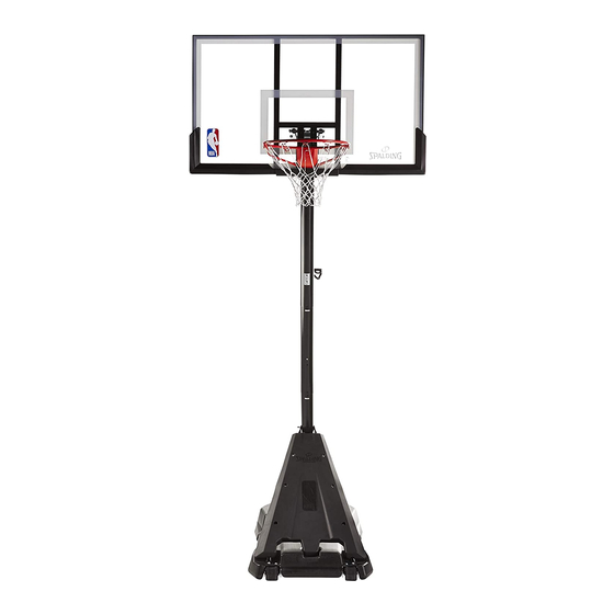
- Seite 7 Get to know the basic parts of your basketball system... Front View BACKBOARD ELEVATOR SYSTEM TOP POLE SECTION MIDDLE POLE SECTION FRONT PANEL BOTTOM POLE SECTION BASE WHEEL CARRIAGE...
- Seite 8 PARTS LIST - See Hardware Identifier Item Qty. Part No. Description Item Qty. Part No. Description 600267 Base 201682 Spacer, 0.530 I.D. x 1.875 901009 Strut, Pole to Base 900867 Plate, Triangle, (Black) 900953 Lift Assembly 600137 Cap, Pole Top FR908006 Top Pole Section 200520 Screw, #8 x 3/4 Long 901453 Middle Pole Section 202605...
- Seite 9 HARDWARE IDENTIFIER (BOLTS & SCREWS) #16 (2) #47 (6)* 208505 #29 (4) #52 (1) #21 (2) #18 (4) 201596 Screw 1/4 x 1. 203153 hex head bolt 5/16 x 3/4 #39 (2) #12 (1) #60 (4) 202871 - SCREW HEX WASHR HD TAP SLOTTED 1/4 X 3/4 #50 (2) #40 (1) #59 (2)
- Seite 10 HARDWARE IDENTIFIER (PLASTIC SPACERS CAPS & CLIPS) #53 (1) #30 (4) #26 (4) #36 (2) #45 (1) HARDWARE IDENTIFIER (OTHER) #56 (1) #17 (1) #27 (1) #54 (1) #57 (1)
- Seite 11 SECTION A: ASSEMBLE THE BASE This is what your system will look like when you’ve finished this section. TOOLS REQUIRED FOR THIS SECTION Wrenches: (2) Socket Wrenches (2) 1/2” and (2) 9/16” and Sockets And/Or 1/2” Extension 9/16” Hammer Phillips-Head Screwdriver...
- Seite 12 Complete wheel assembly as shown in Figure A. Secure wheel bracket (7), wheel (8), axle (9) to the base (1) with bolt (18) and washer (51). Leave bolt and washer attacment to outboard holes until attaching struts (2) to base in step 7. Fig.
- Seite 13 Correctly identify each pole section. With a marker or tape, measure then mark a line 3 1/2” from top end of poles (5 & 6). Marked Line 3 1/2” (8,9 cm) Marked Line 3 1/2” (8,9 cm) TOP POLE MIDDLE POLE BOTTOM POLE STOP AND CALL CUSTOMER SERVICE IF YOU HAVE ANY QUESTIONS OR NEED ASSISTANCE...
- Seite 14 While maintaining alignment of dimple and trough, bounce middle pole section (5) into top pole section (4) using a wood scrap as shown until the top pole (4) is aligned with the marked line on the middle pole (5). You should have a 3 1/2” (8,9 cm) of overlap when properly assembled. CAUTION! WHEN PROPERLY POUNDED TOGETHER, THE POLE SECTIONS...
- Seite 15 While maintaining alignment of dimple and trough, bounce top and middle pole assembly (4 and 5) onto bottom pole section (6) using a wood scrap as shown. Bounce until the top and middle pole assembly (4 and 5) is aligned with the marked line on the bottom pole (6).
- Seite 16 Attach pole (6) assembly to base (1) as shown. Secure pole assembly to base using bolts (50) and pole mounting bracket (49) as shown. WARNING! TWO CAPABLE ADULTS REQUIRED FOR THIS PROCEDURE. FAILURE TO FOLLOW THIS WARNING COULD RESULT IN SERIOUS INJURY AND/OR PROPERTY DAMAGE.
- Seite 17 Rotate non-secured ends of base struts (2) outward to outboard mounting holes in base. Secure ends of base struts (2) to wheel brackets (7) using bolts (18), washers (51) as shown. IMPORTANT! DO NOT TIGHTEN COMPLETELY. WARNING! TWO CAPABLE ADULTS REQUIRED FOR THIS PROCEDURE.
- Seite 18 Install pole mount bracket (15) and reinforcement bracket (42) with carriage bolts (16) as shown. Tighten flange nuts (14) completely. Install lift handle assembly (3) to previously installed pole mount bracket (15) as shown. Tighten hex nut (14) completely with bolt (52).
- Seite 19 SECTION B: ATTACH THE BACKBOARD This is what your system will look like when you’ve finished this section. TOOLS REQUIRED FOR THIS SECTION (2) Socket Wrenches and Sockets Wrenches: (2) 1/2”, (2) 9/16”, and (2) 3/4” And/Or 1/2” 9/16” 3/4” Extension Phillips-Head Screwdriver Sawhorse...
- Seite 20 Identify elevator tubes. Note length and hole placement. Toward Pole Upper Elevator tube Lower Elevator tube Toward Board ID# M6611642 06/09...
- Seite 21 While the system is securely resting on the sawhorse. Install triangle plates (37) to top pole section (4) using bolt (40) and nut (31) as shown. NOTE WARNING! TEST-FIT LARGE BOLTS INTO LARGE HOLES OF ELEVATOR TUBES, BACKBOARD BRACKETS, TWO PEOPLE REQUIRED FOR THIS AND TRIANGLE PLATES.
- Seite 22 While the system is securely resting on the sawhorse. Install elevator tubes (32 and 35) to triangle plates (37) and top pole section (4) using bolts (29) spacers (30 and 45) and nuts (31) as shown. Install pole cap (38) at this time. WARNING! TIGHTEN BOLT (29) IN LOCK NUT (31) UNTIL FLUSH (EVEN) WITH LOCK NUT’S OUTER EDGE.
- Seite 23 Install handle lift assembly to lower elevator tubes (32) using bolt (29), spacers (36), and nut (31) as shown. NOTE: WARNING! Before going on to next step, make sure TIGHTEN BOLT (29) IN LOCK NUT (31) UNTIL FLUSH (EVEN) WITH LOCK NUT’S OUTER EDGE. adjustable system assembly is set to the 10’...
- Seite 24 While the system is securely resting on the sawhorse: Attach lower elevator tubes (32) and counter balance springs (33) to backboard using spacers (26), bolt (59), and nut (11) as shown. WARNING! WARNING! TWO PEOPLE REQUIRED FOR THIS USE EYE PROTECTION WHEN PROCEDURE.
- Seite 25 Assemble upper elevator tubes (35) to backboard using bolt (59), plastic spacers (26), and nut (11) as shown. WARNING! WARNING! USE EYE PROTECTION WHEN TWO PEOPLE REQUIRED FOR THIS INSTALLING SPRINGS. PROCEDURE. FAILURE TO FOLLOW THIS WARNING COULD RESULT IN SERIOUS INJURY AND/OR PROPERTY DAMAGE.
- Seite 26 Insert bolt (29) through left side upper elevator tube (35), then stretch springs (33) onto bolt (29). Insert bolt (29) through right side upper elevator tube (35) and secure with nut (31). WARNING! WARNING! USE EYE PROTECTION WHEN TIGHTEN BOLT (29) IN LOCK NUT (31) UNTIL INSTALLING SPRINGS.
- Seite 27 Install Slam Jam Rim to Backboard Lower Board to lowest setting before standing the system upright. Prior to assembly peel protective film from surface of acrylic backboard. Insert T-bolt (55) into Slam Jam bracket (54) then, attach that assembly to board using bolts (44) and nuts (14).
- Seite 28 Install Slam Jam Rim to Backboard A. Fit rim (34) securely into bracket (54) as shown. Allow T-bolt (55) to slip through center hole in rim (34). B. Install reinforcement bracket (56) onto T-bolt (55) as shown. C. Install spring (57) onto T-bolt (55) as shown. D.
- Seite 29 Roll completed assembly to desired position. Fill base with approximately 37 gallons (140 Liters) of water or approximately 400 lbs. (181 kg) sand and rotate the caps (41,13) into base (1). WARNING! Caps (41, 13) MUST be tightened COMPLETELY and SECURELY to prevent leakage.
- Seite 30 SECTION C: APPLY HEIGHT ADJUSTMENT AND MOVING LABEL Apply height adjustment and moving label (46) to front of pole as shown. WARNING! TWO CAPABLE ADULTS REQUIRED FOR THIS PROCEDURE. FAILURE TO FOLLOW THIS WARNING COULD RESULT IN SERIOUS INJURY AND/OR PROPERTY DAMAGE. NOTE: Peel protective film from surface of acrylic backboard prior to use.
- Seite 31 SECTION D: BOARD PAD Using the holes which line up for your board size, attach left (24) and right (23) board pads and center (22) board pad section to backboard using screws (21 and washers (20) as shown. Fig. A NOTE: Part # 201580 center board pad section (22) is not used on 44”...
- Seite 32 SECTION E: COVER Using screws (39) attach cover (19) to rim (34) as shown. Peel and attach NBA logo (17) to cover (19).
- Seite 33 Número telefónico sin costo del Departamento de Servicio al Cliente en EE.UU.: 1-800-558-5234, Para Canadá: 1-800-284-8339, Para Europa: 00 800 555 85234 (Suecia: 009 555 85234), Para Australia: 1300 367 582 Dirección en Internet: www.spalding.com www.spalding.com.au Gratis nummer klantenservice voor de VS: 1-800-558-5234, Voor Canada: 1-800-284-8339, Voor Europa: 00 800 555 85234 (Zweden: 009 555 85234), Voor Australië: 1300 367 582...
- Seite 34 OUTILS ET MATÉRIEL BENÖTIGTE WERKZEUGE HERRAMIENTAS Y BENODIGD GEREEDSCHAP REQUIS: UND MATERIALIEN: MATERIALES REQUERIDOS: EN MATERIAAL: • Deux (2) adultes • Zwei (2) zur • Twee (2) bekwame • Dos (2) adultos capables Ausführung dieser volwassenen capaces Arbeit fähige Erwachsene • Mètre • Meetlint 4,5 m • Cinta de medir • Maßband (15’) • Planche en bois (chute) • Holzstück (Ausschuß) • Tabla de madera • Tabla de madera (un trozo)
- Seite 35 AVANT DE COMMENCER! VORBEREITENDE MASSNAHMEN ¡ANTES DE COMENZAR! VOOR U BEGINT! Pour garantir l’utilisation optimale du panneau, les composants du système élévateur et la visserie doivent être bien ajustés (serrés). À titre d’essai, insérez les gros boulons dans les gros trous des tubes du système élévateur, des supports du panneau et des plaques triangulaires.
- Seite 37 WAARSCHUWING! Zorg dat u de bedieningshandleiding goed hebt geiezen voordat u dit toestel gebruikt. Indien de gebruiksaanwijzing niet wordt gevolgd, kan letsel of materile schade ontstaan. De eigenaar dient erop toe te zien dat alle spelers deze regels voor veilig gebruik van het systeem kennen en ze in acht nemen. •...
- Seite 38 CONSIGNES DE SÉCURITÉ INSTRUCCIONES DE SEGURIDAD AVERTISSEMENT AVERTISSEMENT AVERTISSEMENT Lisez les avertissements indiqués Lisez les avertissements indiqués Lisez les avertissements indiqués ci-dessous avant d'utiliser ce produit. ci-dessous avant d'utiliser ce produit. ci-dessous avant d'utiliser ce produit. SUIVEZ CES CONSIGNES DE SÉCURITÉ SOUS PEINE DE PROVOQUER DES BLESSURES GRAVES, DES DÉGÂTS EL INCUMPLIMIENTO DE ESTAS INSTRUCCIONES DE SEGURIDAD PUEDE DAR COMO RESULTADO LESIONES GRAVES O DA—OS MATERIALES Y ANULARÁ...
- Seite 39 HOOGTE-AFSTELLING HET DOELBORD AFSTELLEN: 1. Houd de handgreep vast en druk knoop. Size = 2. Verhoog of laat naar Corne gewenste hoogte neer. Die Cu 3. Geef knoop vrij. 3.25 M All Te HET SYSTEEM VERPLAATSEN 1 Mil. 1. Zet het basketbal doelbord Illustr in de laagste stand.
- Seite 40 ENREGISTREMENT DU PRODUIT : Por favor recuerde completar en línea el formulario de Rappelez-vous de remplir votre formulaire d’inscription du registro de su producto en: www.spalding.com/customer_ produit en ligne sur la page www.spalding.com/customer_ support/product_registration. support/product_registration. PRODUKTREGISTRIERUNG: REGISTRATIE VAN HET PRODUCT:...
-
Seite 41: Hinweis Für Die Personen, Die Den Zusammenbau Durchführen
AVIS AUX PERSONNES CHARGÉES DU MONTAGE Assemblage exclusivement réservé à un adulte. Jetez TOUT le matériel d’emballage dans les plus brefs délais. Comme pour tous les produits pour enfants, inspectez périodiquement le serrage des pièces de petite taille. Une fois assemblé, l’ensemble DOIT être rempli de sable ou d’eau à TOUT MOMENT. TOUS les systèmes de basket-ball, y compris ceux utilisés en EXPOSITION, DOIVENT être assemblés et installés conformément aux instructions. Suivez ces instructions sous peine d’encourir des BLESSURES GRAVES. Il est INACCEPTABLE de composer un système de soutien de fortune. HINWEIS FÜR DIE PERSONEN, DIE DEN ZUSAMMENBAU DURCHFÜHREN Zusammenbau nur durch Erwachsene. ALLE Verpackungsmaterialien sofort wegwerfen. Wie alle Produkte muss auch dieses regelmäßig auf lose Kleinteile inspiziert werden. Die zusammengebaute Einheit MUSS STETS mit Sand oder Wasser gefüllt sein. ALLE Basketballsysteme, einschließlich der zu AUSSTELLZWECKEN benutzten Systeme, MÜSSEN gemäß den Anleitungen zusammengebaut und aufgestellt werden. Ein Missachten dieser Anleitungen kann SCHWERE VERLETZUNGEN zur Folge haben.Zum Beschweren darf NICHT zu irgendwelchen Notbehelfsmaßnahmen gegriffen werden. AVISO PARA LAS PERSONAS QUE REALIZAN EL MONTAJE Es necesario que el montaje sea realizado por adultos. Deseche inmediatamente TODOS los materiales de embalaje. Al igual que con cualquier producto, inspeccione periódicamente para verificar que todas las piezas pequeñas estén firmemente apretadas. La unidad montada DEBE estar llena de arena o agua en TODO momento. TODOS los sistemas de baloncesto, inclusive los de EXHIBICIÓN, DEBEN estar montados e instalados de acuerdo con las instrucciones. Si no se siguen las instrucciones se podría ocasionar una LESIÓN SERIA. NO es aceptable improvisar un sistema de soporte temporal. KENNISGEVING VOOR MONTEURS De montage dient door volwassenen te gebeuren. Gooi AL het verpakkingsmateriaal meteen weg. ALLE basketbalsystemen, ook SHOWMODELLEN, MOETEN in elkaar worden gezet en met zand of water gestabiliseerd worden volgens de gebruiksaanwijzing. - Seite 42 LISTE DES PIÈCES - Voir légende Légende Qté No. de réf. Description Légende Qté No. de réf. Description 600270 Socle 900867 Plaque triangulaire (noire) 901009 Contrefiche, poteau/socle 600137 Capuchon, haut du poteau 900953 Ascenseur Assemblée 200520 Vis, #8 x 19 mm long. FR908006 Section de poteau supérieure 202605 Boulon, 6 pans, 1/2-13 x 10,7 cm (long) 901453 Section de poteau centrale 203617...
- Seite 43 TEILELISTE - Siehe Teileschlüssel Nr. Anz. Teilenummer Beschreibung Nr. Anz. Teilenummer Beschreibung 901454 Unteres Verlängerungsrohr – lang 600270 Sockel 204838 Gegengewichtsfeder 901009 Verstrebung, Stange zu Sockel Korbrand 900953 Aufzug Versammlung 901401 Oberes Verlängerungsrohr – kurz FR908006 Oberes Stangenteil 201682 Abstandsstück, 0,530” ID x 1,875” Länge 901453 Mittleres Stangenteil 900867...
- Seite 44 LISTA DE PIEZAS - Vea el identificador de herraje Artículo Cant. Pieza N.º Descripción Artículo Cant. Pieza N.º Descripción 600270 Base 900867 Placa triangular, (negra) 901009 Puntal, poste a base 600137 Tapa, parte superior del poste 900953 Asamblea de Ascensor 200520 Tornillo, #8 x 3/4 de longitud FR908006 Sección superior del poste 202605 Perno hexagonal 1/2-13 x 4.25 de 901453...
- Seite 45 ONDERDELENLIJST - zie identificatie bevestigingsmateriaal Stuk Aantal Onderdeel nr Beschrijving Stuk Aantal Onderdeel nr Beschrijving 37 2 900867 Plaat, driehoekig, (zwart) 1 600270 Voetstuk 38 1 600137 Dop, bovenkant paal 2 901009 Steun, paal naar voetstuk 39 2 200520 Schroef, nr. 8 x 3/4 inch lang 1 900953 Hoogtesysteem 40 1 202605...
- Seite 46 IDENTIFICATION DES PIÈCES (BOULONS & VIS) BEFESTIGUNGSTEILESCHLÜSSEL (BOLZEN UND SCHRAUBEN) IDENTIFICADOR DE HERRAJE (PERNOS Y TORNILLOS) IDENTIFICATIESLEUTEL VOOR HET BEVESTIGINGSMATERIAAL (BOUTEN EN SCHROEVEN) #16 (2) #47 (6)* 208505 #29 (4) #21 (2) #52 (1) #18 (4) 201596 Screw 1/4 x 1. 203153 hex head bolt 5/16 x 3/4 #39 (2) #12 (1) #60 (4) 202871 - SCREW HEX WASHR HD TAP SLOTTED 1/4 X 3/4 #50 (2) #40 (1) #59 (2)
- Seite 47 IDENTIFICATION DES PIÈCES (ENTRETOISES, CAPUCHONS & PINCES EN PLASTIQUE) BEFESTIGUNGSTEILESCHLÜSSEL (ABSTANDSSTÜCKE, KAPPEN UND CLIPS AUS KUNSTSTOFF) IDENTIFICADORES DEL HERRAJE (TAPAS DE LOS ESPACIADORES Y SUJETADORES DE PLÁSTICO) IDENTIFICATIESLEUTEL VOOR HET BEVESTIGINGSMATERIAAL (PLASTIC AFSTANDSTUKKEN, DOPPEN EN KLEMMEN) #53 (1) #30 (4) #26 (4) #45 (1) #36 (2) IDENTIFICATION DES PIÈCES (AUTRES) BEFESTIGUNGSTEILESCHLÜSSEL (SONSTIGE) IDENTIFICADOR DE HERRAJE (OTROS) IDENTIFICATIESLEUTEL VOOR HET BEVESTIGINGSMATERIAAL (OVERIGE) #27 (1) #56 (1) #17 (1) #54 (1) #57 (1)
- Seite 48 SECTION A: MONTAGE DU SOCLE BAUABSCHNITT A: ZUSAMMENBAU DES SOCKELS SECCIÓN A: MONTAJE DE LA BASE DEEL A: HETVOETSTUK ASSEMBLEREN Voici à quoi ressemblera votre système lorsque vous en aurez fini avec cette section. So sieht das System aus, wenn Sie mit diesem Bauabschnitt fertig sind. Así es como se verá su sistema cuando haya terminado esta sección.
- Seite 49 Effectuez le montage des roues, comme indiqué à la figure A. Fixez le support de roues (7), la roue (8), l’axe (9) et les écrous (13) sur le socle (1) à l’aide du boulon (18) et de la rondelle (51). Faites de même pour la roue opposée. Den Rest der Radmontage wie in Abbildung A gezeigt durchführen.
- Seite 50 Placez des repères sur les sections de poteau avec du ruban adhésif (non fourni), comme illustré. Die Stangenteile wie gezeigt mit Klebeband (nicht im Lieferumfang enthalten) markieren. Marque con cinta las secciones del poste (no se suministran), como se muestra. Markeer met opneem de onderdelen van de post (leverde niet), zoals getoond is.
- Seite 51 REMARQUE : Si MINIMUM PÔLE ENGAGEMENT NE PEUT PAS ÊTRE ATTEINT !! STOP !! NE PASSEZ PAS À L’ÉTAPE SUIVANTE ! - APPEL SPALDING SERVICE CLIENT POUR ASSISTANCE. Mit einer Markierung oder Messband markieren Sie eine Linie 3 1/2” (8.9 cm) von oberstem Ende der mittlerer Stange (5). Springen Sie während Erhaltung von Ausrichtung mittlerer Stangenabschnitt (5) in obersten Abschnitt (4) benutzend einen Holzfetzen wie gezeigt, bis...
- Seite 52 REMARQUE : Si MINIMUM PÔLE ENGAGEMENT NE PEUT PAS ÊTRE ATTEINT !! STOP !! NE PASSEZ PAS À L’ÉTAPE SUIVANTE ! - APPEL SPALDING SERVICE CLIENT POUR ASSISTANCE. Mit einer Markierung oder Messband markieren Sie eine Linie 3 1/2” von oberstem Ende der unterer Stange (6). Sprungsoberteil und mittlere Stangenversammlung (4 und 5) auf unteren Stangenabschnitt (6) benutzend einen Holzfetzen wie gezeigt.
- Seite 53 Attachez le poteau au socle (1), comme illustré. Fixez le poteau au socle à l’aide des boulons (50) et du support de poteau (49), comme illustré. Den Stangenaufbau wie gezeigt am Sockel (1) befestigen. Den Stangenaufbau mit Schrauben (50) und der Stangenmontagehalterung (49) wie gezeigt am Base befestigen.
- Seite 54 Fixez les contrefiches du socle (2) au poteau, de la façon illustrée. Coiffez l’extrémité dénudée du boulon avec un capuchon (53), comme illustré Die Baseverstrebungen (2) wie gezeigt an der Stange befestigen. Die Abdeckung (53) wie gezeigt auf das freiliegende Ende der Schraube aufsetzen.
- Seite 55 Tournez les extrémités non-fixées des contrefiches de base (2) à l’extérieur jusqu’aux trous de montage dans la base comme montrée. Fixez les extrémités des contrefiches de base (2) aux parenthèses de roue (7) utilisant les boulons (18), les rondelles (51) comme montré. Drehen Sie nicht-gesicherte Enden der Unterseitenspreizen (2) außerhalb zu den Entlüftungslöchern in der Unterseite wie gezeigt.
- Seite 56 Fixez le couvercle (28) aux contrefiches du réservoir (2) à l’aide des boulons (47) et des écrous (48), comme illustré. Die Abdeckung (28) wie gezeigt mit Schrauben (47) und Muttern (48) an den Tankverstrebungen (2) befestigen. Asegure la cubierta (28) en los puntales del tanque (2) usando pernos (47) y tuercas (48) como se muestra. Maak de afdekking (28) vast aan de steunen op het voetstuk (2) met de bouten (47) en moeren (48), als afgebeeld.
- Seite 57 Installer le crochet de mont de pôle (15) et le crochet de renforcement (42) avec les boulons de calèche (16) comme indiqué. Resserrer les écrous de bride (14) complètement. Installieren Sie Stangenuntersatzbügel (15) und Verstärkungsbügel (42) mit Kutschenschrauben (16) wie gezeigt. Ziehen Sie Flanschmuttern (14) vollständig fest.
- Seite 58 SECTION B: ATTACHEZ LE PANNEAU BAUABSCHNITT B: ANBRINGEN DER KORBWAND SECCIÓN B: CONECTE EL RESPALDO DEEL B: MAAK HET DOELBORD VAST Voici à quoi ressemblera votre système lorsque vous en aurez fini avec cette section. So sieht das System aus, wenn Sie mit diesem Bauabschnitt fertig sind. Así es como se verá su sistema cuando haya terminado esta sección. Dit is hoe het systeem eruit ziet wanneer u klaar bent met dit deel.
- Seite 59 Repérez les tubes du dispositif élévateur (35 et 32). Die Verlängerungsrohre (35 u. 32) zurecht legen. Identifique los tubos elevadores (35 y 32). Identificeer de liftbuizen. (35) EN 32) Vers Le Poteau Zur Stange Hin Hacia El Poste Naar De Paal Tube supérieur du dispositif élévateur Tube inférieur du dispositif élévateur Oberes Verlängerungsrohr...
- Seite 60 Appuyez le poteau sur le banc de sciage. Attachez les plaques triangulaires (37) et les tubes du système élévateur (35 & 32) au poteau supérieur (4) à l’aide des boulons (40 & 29), spacers (45) & (30) et des écrous (31). Installez le capuchon du poteau (38).
- Seite 61 Installez le montage d’ascenseur de poignée (3) pour abaisser les tubes d’ascenseur (32) utilisant le boulon (29), les entretoises (36), et l’écrou (31) comme montré. Bringen Sie Handgriffaufzugbaugruppe (3) an, um Aufzugsschläuche (32) unter Verwendung Schraubbolzens (29), der Distanzscheiben (6) und der Nuss (31) wie gezeigt zu senken. Instale el montaje de la elevación de la manija (3) para bajar los tubos del elevador (32) usando el perno (29), los espaciadores (36), y la tuerca (31) como se muestra.
- Seite 62 Attachez les tubes inférieurs d’ascenseur (32) et les contre- ressorts compensateurs (33) aux supports de panneau arrière (59) utilisant les entretoises (26), le boulon (59), et l’écrou (11) comme montré. Bringen Sie unterere Aufzugsschläuche (32) und Gegengewichtfedern (33) zu den RückenbretHaltewinkeln (59) unter Verwendung der Distanzscheiben (26), Schraubbolzens (59) und der Nuss (11) wie gezeigt an.
- Seite 63 Fixez les tubes supérieurs du système élévateur (35) sur les supports du panneau (27) à l’aide des entretoises (26), du boulon (59) et de l’écrou (11), comme illustré. Die oberen Verlängerungsrohre (35) wie gezeigt mit Abstandsstücken (26), Schraube (59) und Mutter (11) an den Korbwandklammern (59) befestigen.
- Seite 64 Insérez le boulon à T (55) dans le suport de cerceau (54), puis attachez l’ensemble au panneau à l’aide des boulons (44) et des écrous (14). Die T-Nutenschraube (55) in die Korbrandhalterung (54) einsetzen; dann diese Baugruppe mit Schrauben (44) und Muttern (14) an der Korbwand befestigen.
- Seite 65 Insérer le boulon (29) dans le tube élévateur supérieur gauche (35), puis étirer les ressorts (33) sur le boulon (29). Insérez le boulon (29) dans le tube élévateur supérieur droit (35) et fixez-le avec l’écrou (31). Setzen Sie den Bolzen (29) durch das linke obere Höhenrohr (35) ein und strecken Sie die Federn (33) auf den Bolzen (29). Schraube (29) durch rechtes oberes Aufzugsrohr (35) einsetzen und mit Mutter (31) sichern.
- Seite 66 REMARQUE: / HINWEIS: NOTA: / OPMERKING: ORIENTATION DU SUPPORT AUSRICHTUNG DER HALTERUNG ORIENTACIÓN DEL SOPORTE ORIËNTATIE VAN STEUN 1/8” (3mm)
- Seite 67 Installez le cerceau Slam Jam sur le panneau. A. Calez bien le cerceau (34) dans le support (54), comme illustré. Laissez glisser le boulon à T (55) à travers le trou central du cerceau (34). B. Installez le support de renforcement (56) sur le boulon à T (55), comme illustré. C.
- Seite 68 AVERTISSEMENT! / WARNUNG! ¡ADVERTENCIA! / WAARSCHUWING! VÉRIFIEZ LE NIVEAU D’EAU AVANT AVANT CHAQUE UTILISATION ! Le bouchon (41, 13) DOIT être serré À FOND pour éviter les fuites. DEN WASSERSTAND VOR JEDEM Der Schraubverschluss (41, 13) MUSS VOLLSTÄNDIG und FEST aufgeschraubt werden, um Lecks zu verhindern. GEBRAUCH ÜBERPRÜFEN! La tapa (41,13) DEBE estar COMPLETA y SEGURAMENTE apretada para evitar fugas.
- Seite 69 SECTION C : APPLIQUEZ L’ÉTIQUETTE DE HAUTEUR ET DE DÉPLACEMENT ET DE RÉGLAGE DE HAUTEUR BAUABSCHNITT C: ANBRINGUNG DES HÖHENEINSTELL- UND TRANSPORTAUFKLEBERS UND HÖHENEINSTELLUNG SECCIÓN C: APLICACIÓN DE LA ETIQUETA DE ALTURA Y MOVIMIENTO Y AJUSTE DE LA ALTURA DEEL C: LABEL AANBRENGEN VOOR HOOGTE EN VERPLAATSEN EN INSTELLEN VAN HOOGTE Collez l’étiquette d’échelle de hauteur et de déplacement (46) sur l’avant du REMARQUE: Décollez le film de...
-
Seite 70: Height Adjustment
HEIGHT ADJUSTMENT JUSTEMENT DE TAILLE INSTRUCTIONS: / HÖHENVERSTELLUNG INSTRUCTIONS: AJUSTE de ALTURA INSTRUCTIONS: / HET DOELBORD AFSTELLEN INSTRUCTIONS: A. La poignée de Compréhension d’a. et le bouton de presse pour déclencher l’épingle de verrouillage interne. B. Légèrement la poignée de mouvement et le relâchement boutonnent. L’objectif d’Augmentation de c. à réglant haut (10 pieds). TO ADJUST BACKBOARD: C. - Seite 71 SECTION D : REMBOURRAGE DU PANNEAU BAUABSCHNITT D: KORBWANDPOLSTERUNG SECCIÓN D: ALMOHADILLA DEL TABLERO DEEL D: STOOTKUSSEN DOELBORD En utilisant les trous d’alignement correspondant à la taille de votre Attachez les sections de rembourrage gauche et droite sur le panneau, attachez la section centrale de rembourrage aux sections panneau avec les vis et les rondelles, comme illustré.
- Seite 72 SECTION E : PROTECTION BAUABSCHNITT E: ABDECKUNG SECCIÓN E: CUBIERTA DEEL E: AFDEKKING L’utilisation visse (39) attache la couverture Peler et attacher le logo de NBA (17) couvrir (19). (19) au bord (34) comme indiqué. Schälen Sie und befestigen Sie NBA Firmenzeichen Gebrauch schraubt (39) befestigt Decke (19) (17) zu bedecken (19).