SPALDING AA73351 Gebrauchsanleitung
Inhaltsverzeichnis
Quicklinks
Inhaltsverzeichnis

Verwandte Anleitungen für SPALDING AA73351


Inhaltszusammenfassung für SPALDING AA73351
- Seite 1 Portable Basketball System Owners Manual 12/15 M731040 © COPYRIGHT 2015 by SPALDING...
- Seite 2 Système portable - Manuel de l'utilisateur Gebrauchsanleitung für tragbare Systeme Manual del Propietario del Sistema Portátil...
- Seite 3 (Schweden: 009 555 85234), für Australien: 1300 367 582 Internet-Adresse: www.spalding.com www.spalding.com.au Número telefónico sin costo del Departamento de Servicio al Cliente en EE.UU.: 1-800-558-5234, Para Canadá: 1-800-284-8339, Para Europa: 00 800 555 85234 (Suecia: 009 555 85234), Para Australia: 1300 367 582 Dirección en Internet: www.spalding.com www.spalding.com.au...
-
Seite 4: Required Tools And Materials
HERRAMIENTAS BENÖTIGTE OUTILS ET REQUIRED TOOLS Y MATERIALES WERKZEUGE MATÉRIEL REQUIS: AND MATERIALS: REQUERIDOS: UND MATERIALIEN: • Zwei (2) zur • Deux (2) • Dos (2) adultos Ausführung • 2 Capable adultes capaces dieser Arbeit Adults capables fähige • Cinta de medir Erwachsene •... - Seite 5 BEFoRE yoU START! AVANT DE CoMMENCER! VoRBEREITENDE MASSNAHMEN ¡ANTES DE CoMENZAR! STOP! STOP! ¡ ¡ ALTO! ALTO! HALT! HALT! ¡ ¿ To ensure optimal playability of backboard system, a close tolerance fit between the elevator components and hardware is required. Test-fit large bolts into large holes of elevator tubes, backboard brackets, and triangle plates. Carefully rock them in a circular motion to ream out any excess paint from holes if necessary.
- Seite 6 WARNING Read and understand warnings listed below before using this product. Failure to follow these warnings may result in serious injury and/or property damage. Owner must ensure that all players know and follow these rules for safe operation of the system. •...
-
Seite 8: Safety Instructions
SAFETy INSTRUCTIoNS FAIlURE To FolloW THESE SAFETy INSTRUCTIoNS MAy RESUlT IN SERIoUS INjURy oR PRoPERTy DAMAGE AND WIll VoID WARRANTy. Owner must ensure that all players know and follow these rules for safe operation of the system. To ensure safety, do not attempt to assemble this system without following the instructions carefully. -
Seite 9: Sicherheitshinweise
SICHERHEITSHINWEISE EIN MISSACHTEN DIESER SICHERHEITSHINWEISE KANN ZU SCHWEREN VERlETZUNGEN oDER SACHSCHÄDEN FÜHREN UND MACHT DIE GARANTIE UNWIRKSAM. Der Eigentümer muss sicherstellen, dass alle Spieler diese Regeln für einen sicheren Betrieb des Systems kennen und befolgen. Aus Sicherheitsgründen darf dieses System nur unter sorgfältiger Beachtung der Anleitung zusammengebaut werden. -
Seite 10: Height Adjustment
HEIGHT ADJUSTMENT RÉGLAGE DE LA HAUTEUR TO ADJUST BACKBOARD: POUR AJUSTER LE PANNEAU : 1. Grasp handle and press button. 1. Saisissez la poignée et appuyez sur le bouton. 2. Raise or lower to desired height. 2. Remontez ou abaissez à la hauteur 3. - Seite 11 Sistema de baloncesto Garantía de dueños Para la última información de garantía del sistema de baloncesto Por favor visite el sitio web de Spalding Basketball en www.Spalding.com 1-800-558-5234 Póngase en contacto con servicio al cliente de Spalding en teléfono #...
- Seite 12 KÖNNEN ZU DEREN PlÖTZlICHEM BRUCH FÜHREN. WENN DIE KoRBWAND VoR oDER NACH DEM ZUSAMMENBAU IN jEGlICHER WEISE BESCHÄDIGT WIRD, RUFEN SIE DIE FolGENDE GEBÜHRENFREIE TElEFoNNUMMER AN: Innerhalb der USA: 1-800-558-5234; innerhalb KANADAS: 1-800-284-8339; www.spalding.com ¡ADVERTENCIA! SI SU SISTEMA ESTÁ EQUIPADo CoN UN RESPAlDo DE ACRÍlICo, EXAMINE El RESPAlDo PARA VERIFICAR QUE No HAyA SUFRIDo DAÑoS DURANTE El TRANSPoRTE.
-
Seite 13: Hinweis Für Die Personen, Die Den Zusammenbau Durchführen
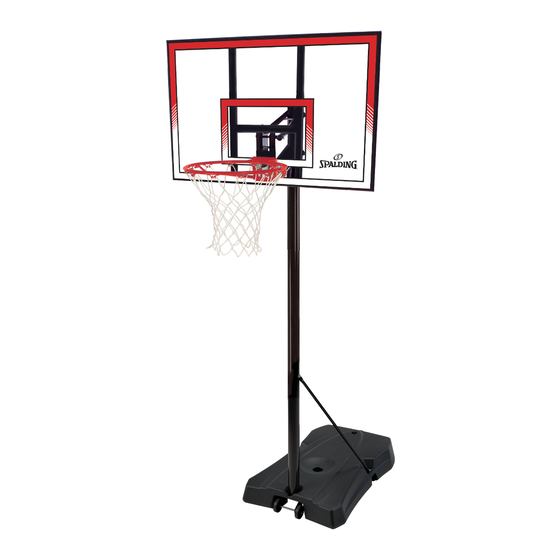
NOTICE TO ASSEMBLERS Adult Assembly Required. Dispose of ALL packaging materials promptly. As with all products, periodically inspect for loose small parts. Assembled unit MUST be filled with sand or water at ALL times. ALL basketball systems, including those used for DISPLAYS, MUST be assembled and installed according to instructions. - Seite 14 Get to know the basic parts of your basketball system... Apprenez à connaître les composants de base de votre système de basket-ball... Machen Sie sich mit den wichtigsten Teilen Ihres Basketballsystems vertraut… Conozca las piezas básicas de su sistema de baloncesto… BACKBOARD PANNEAU KORBWAND...
- Seite 15 PARTS LIST - See Hardware Identifier Item Qty. Part No. Description Item Qty. Part No. Description 600288 Base, (Black) 108846 Wheel Axle 108163 Pole Mount Bracket 266200 Wheel, 3.5” 203231 Bolt, Carriage, 5/16-18 x 3.5” Long FR908347 Top Pole Section - Black 201681 Spacer 0.53 I.D.
- Seite 16 LISTE DES PIÈCES - Voir légende Légende Qté No. de réf. Description Légende Qté No. de réf. Description 203617 Bouchon, socle 600288 Socle (noir) Cerceau 108846 Axe des roues Filet 266200 Roue, 8,9 cm (noire) 108163 Support de poteau FR908347 Section de poteau supérieure - Noir 203231 Boulon ordinaire, 5/16-18 x 8,89 cm (long.) FR908268 Section de poteau centrale - Noir...
- Seite 17 TEILELISTE - Siehe Teileschlüssel Nr. Anz. Teilenummer Beschreibung Nr. Anz. Teilenummer Beschreibung Korbrand 600288 Sockel (schwarz) Netz 108846 Radachse 108163 Stangenmontageklammer 266200 Rad, 3.5” Zoll 203231 Schlossschraube, 5/16-18 x 3.5 Zoll Länge FR908347 Oberes Stangenteil - Schwarz 201681 Abstandsstück, 0.53 ID x 0.88 Zoll Länge FR908268 Mittleres Stangenteil - Schwarz 206049...
- Seite 18 LISTA DE PIEZAS - Vea el identificador de herraje Artículo Cant. Pieza N.º Descripción Artículo Cant. Pieza N.º Descripción 203617 Tapa, base 600288 Base (Negra) Borde 108846 Eje de la rueda 266200 Rueda, 3.5” (8,9 cm) 108163 Soporte de montaje del poste FR908347 Sección superior del poste - Negra 203231 Perno cabeza de carro, 5/16-18 x 3.5”...
- Seite 19 HARDWARE IDENTIFIER (BOLTS AND SCREWS) IDENTIFICATION DES PIÈCES (BOULONS ET VIS) BEFESTIGUNGSTEILESCHLÜSSEL (BOLZEN UND SCHRAUBEN) IDENTIFICADOR DE HERRAJE (PERNOS Y TORNILLOS) #15 (6) #48 (2) #8 (4) #28 (2) #18 (1) #33 (1) #7 (2) #11 (1) #43 (6) HARDWARE IDENTIFIER (NUTS AND WASHERS) IDENTIFICATION DES PIÈCES (ÉCROUS ET RONDELLES) BEFESTIGUNGSTEILESCHLÜSSEL (MUTTERN UND UNTERLEGSCHEIBEN) IDENTIFICADOR DE HERRAJE (TUERCAS Y ARANDELAS)
- Seite 20 HARDWARE IDENTIFIER (PLASTIC SPACERS, CAPS, CLIPS AND OTHER) IDENTIFICATION DES PIÈCES (ENTRETOISES EN PLASTIQUE, CAPUCHONS, PINCES ET AUTRES) BEFESTIGUNGSTEILESCHLÜSSEL (ABSTANDSSTÜCKE, KAPPEN UND CLIPS AUS KUNSTSTOFF UND SONSTIGE TEILE) IDENTIFICADOR DEL HERRAJE (ESPACIADORES DE PLÁSTICO, TAPAS, SUJETADORES Y OTROS) #29 (2) #20 (4) #51 (1) #32 (1) #31 (1) #17 (1)
- Seite 21 SECTIoN A: ASSEMBLE THE BASE SECTIoN A: ASSEMBLAGE DU SOCLE BAUABSCHNITT A: ZUSAMMENBAU DES SOCKELS SECCIÓN A: MONTAJE DE LA BASE ITEMS REQUIRED FoR THIS SECTIoN Remove end cap at end of base to remove This is what your contents. oUTIlS REQUIS PoUR CETTE SECTIoN system will look like Be sure to check inside pole sections,...
- Seite 22 ENGAGEMENT WHICH AlloWS THE HARDWARE To BE ASSEMBlED CANNoT BE ACHIEVED Do NoT PRoCEED To THE NEXT STEP! - CAll SPAlDING CUSToMER SERVICE FoR ASSISTANCE. Tout en maintenant l'alignement, rebondissez la section moyenne de poteau (5) dans la section supérieure (4) utilisant une chute en bois comme montré jusqu'à ce que le poteau supérieur se déplace ligne du thw 3 1/2 à la » (9 cm) vous avez précédemment fait sur le poteau moyen (5).
- Seite 23 ASSEMBlÉES, lES SECTIoNS DE MATÉRIEl ASSEMBlÉ NE PEUT ÊTRE RÉAlISÉ!! SToP!! NE PRoCÉDEZ À l'ÉTAPE PoloNAIS DEVRAIENT AVoIR A 3-1/2" ; SUIVANTE ! -APPElER lE SERVICE À lA ClIENTÈlE SPAlDING À l'AIDE. CHEVAUCHEMENT. WENN SIE RICHTIG ZUSAMMENGEBAUT Schlagoberseite und mittlerer Pfosten (4 und 5) auf unteren Pfosten (6) unter WERDEN, SollTEN DIE PolE- Verwendung eines hölzernen Schrottes wie gezeigt.
- Seite 24 Install wheel axle (2) through wheel bracket (19) wheels (3) and spacer (50) onto wheel axle (2) secure with pushnuts (51). Insert pole assembly into tank assembly as shown. Secure pole (6) to tank (1) and wheel carriage with bolts (7). A deep socket is recommended.
- Seite 25 Secure flat end of tank struts (10) to pole using bolt (11), washer (12), and nut (13), as shown. Fixez l'extrémité plate des contrefiches du réservoir (10) à la perche en utilisant la vis (11), les entretoises (50), la rondelle (12), et l'écrou (13), comme illustré. Das flache Ende der Tankverstrebungen (10) Um die Pole mit der Schraube (11), Distanzstücke (50), Scheibe (12), Mutter (13), wie gezeigt.
- Seite 26 Install pole mount bracket (27) and reinforcement bracket (34) with carriage bolts (28) in middle pole (5) mounting holes as shown. Tighten flange nuts (16) completely. Installez le support de fixation du poteau (27) et le support de renforcement (34) avec les boulons ordinaires (28) dans les trous de fixation de la section de poteau central (5), comme illustré.
- Seite 27 SECTIoN B: ATTACH THE BACKBOARD SECTIoN B: FIXATION DU PANNEAU BAUABSCHNITT B: ANBRINGEN DER KORBWAND SECCIÓN B: CONECTE EL RESPALDO ITEMS REQUIRED FoR THIS SECTIoN This is what your system will look like when you’ve oUTIlS REQUIS PoUR CETTE SECTIoN finished this section.
- Seite 28 Assemble backboard brackets (14) using bolts (8), and nuts (9) as shown. Assemblez les supports de panneau (14) à l’aide des boulons (8) et des écrous (9), comme illustré. Korbwandklammern (14) wie gezeigt mit Schrauben (8) und Muttern (9) zusammenbauen. Monte los soportes del respaldo (14) usando pernos (8) y tuercas (9) como se muestra.
- Seite 29 Attach lower elevator tubes (41) and spring (44) to backboard brackets (14) using spacers (20) bolt (43) and nut (40) as shown. Insert T-bolt (33) through Slam Jam bracket (32) as shown. Secure Slam Jam bracket (32) to backboard. Using bolt (15) and nut (16) as shown. Attachez les tubes inférieurs du système élévateur (41) et le ressort (44) aux équerres du support du panneau (14) à...
- Seite 30 Attach upper elevator tubes (42) to backboard support brackets (14) using spacers (20), bolt (43), and nut (40) as shown. Attachez les tubes supérieurs du système élévateur (42) aux supports du panneau (14) à l'aide des entretoises (20), du boulon (43) et de l'écrou (40), comme illustré. Die oberen Verlängerungsrohre (42) wie gezeigt mit Abstandsstücken (20), Schraube (43) und Mutter (40) an den Korbwandstützklammern (14) befestigen.
- Seite 31 Support pole on sawhorse. Attach upper and lower elevator tubes (41 and 42) to upper pole section (4) using bolts (43) and nuts (40) as shown. Attach pole cap (22) as shown. Appuyez le poteau sur le banc de sciage. Attachez les tubes supérieurs et inférieurs de l'élévateur (41 et 42) à la section de poteau supérieure (4) à...
- Seite 32 Slide inner adjustment tube (39) into outer tube assembly (38) until it snaps in place about midway inside the outer tube assembly (38). Glissez le tube d'ajustement intérieur (39) dans le tube extérieur (38), jusqu'à ce qu'il s'enclenche à mi-distance environ à...
- Seite 33 Attach the inner adjustment tube (39) to pole mount bracket (27) using bolt (18) and nut (13) as shown. Attachez le tube d'ajustement intérieur (39) au support de poteau (27) à l'aide du boulon (18) et de l'écrou (13), comme illustré. Das innere Einstellrohr (39) wie gezeigt mit Schraube (18) und Mutter (13) an der Stangenmontagehalterung (27) befestigen.
- Seite 34 Install Slam jam Rim to Backboard A. Fit rim (25) securely into bracket (32) as shown. Allow T-bolt (33) to slip through center hole in rim (25). B. Install reinforcement bracket (31) onto T bolt (33) as shown. C. Install spring (30) onto T bolt (33) as shown. D.
- Seite 35 NoTE: / REMARQUE: HINWEIS: / NoTA: oRIENTATIoN oF BRACKET oRIENTATIoN DU SUPPoRT AUSRICHTUNG DER HAlTERUNG oRIENTACIÓN DEl SoPoRTE...
- Seite 36 Install cover (47) over spring return mechanism as shown. Installez le couvercle (47) sur le mécanisme de retour du ressort, comme illustré. Die Abdeckung (47) wie über dem Federrückholmechanismus anbringen. Instale la cubierta (47) sobre el mecanismo de retorno de resorte como se muestra.
- Seite 37 Lock elevator system into highest position (the backboard is as high as it will go). Apply 10 ft. height indication sticker (37) to inner adjustment tube (39) directly below arrow on handle as shown. Move elevator system to the next position and apply the 9 1/2 ft. sticker. Repeat until all height settings have been labeled.
- Seite 38 Support system on sawhorse. Extend system to highest position before assembly of spring. Stretch counterbalance spring (44) to upper elevator tubes and secure with with bolt (43) and nut (40) in location shown. Appuyez le système sur le banc de sciage. Tendez le système jusqu’à la position la plus haute avant d’assembler le ressort.
- Seite 39 Instructions for filling with water: Roll completed assembly to desired position. Fill tank with water (approx. 31 gallons / 117 Liters) Tighten both caps (23 and 24) securely into place. Instruction de remplissage avec de l'eau: Roulez l'ensemble jusqu'à la position souhaitée. Remplissez le réservoir d'eau (117 litres environ).
- Seite 40 Instructions for filling with sand: Roll completed assembly to desired position. Carefully tip system forward and fill base with sand (approx. 400 lbs. / 181 kg). DO NOT LEAVE SYSTEM UNATTENDED! When the base is filled completely tighten both caps (23 and 24) securely into place.
- Seite 41 IMPoRTANT! / IMPoRTANT! WICHTIG! / ¡IMPoRTANTE! No matter which hole is used for filling, BoTH caps MUST be tightened CoMPlETEly and SECUREly to prevent leakage. Quel que soit le trou utilisé pour le remplissage, lES DEUX bouchons DEVRoNT être serrés À FoND pour éviter les fuites. Unabhängig davon, durch welche Öffnung der Tank gefüllt wird, MÜSSEN BEIDE Schraubverschlüsse VollSTÄNDIG und FEST aufgeschraubt werden, um lecks zu verhindern.
-
Seite 42: Réglage De La Hauteur
Apply the height adjustment and moving label (21) to the front of the pole as shown. Collez l’étiquette d’échelle de hauteur et de déplacement (21) sur l’avant du poteau, comme illustré. Höhenverstell- und Transportaufkleber (21) wie gezeigt an der Vorderseite der Stange anbringen. Aplique la etiqueta de ajuste de la altura y de movimiento (21) en la parte frontal del poste, como se muestra. - Seite 43 SECTIoN C: BOARD PAD SECTIoN C: REMBOURRAGE DU PANNEAU BAUABSCHNITT C: KORBWANDPOLSTERUNG SECCIÓN C: ALMOHADILLA DEL TABLERO PARTS LIST / LISTE DES PIÈCES / TEILELISTE / LISTA DE PIEZAS (See Hardware Identifier) / (Voir la légende des illustrations) / (Siehe Befestigungsteileschlüssel) / (Vea el identificador de herraje) Item Qty.
- Seite 44 Using the holes which line up for your board size, attach Attach left and right pad sections to board using screws and center pad section to left and right sections and board washers as shown. using screws and washers as shown. Attachez les sections de rembourrage gauche et droite sur En utilisant les trous d'alignement correspondant à...
- Seite 45 NoTE: Depending on your model this step may not be required. NoTE: Dépendre de votre modèle que cette étape ne pourrait pas être exigée. Anmerkung: Hängt von Ihrem Modell dieser Schritt darf nicht erfordert werden ab. la NoTA: Dependiendo de su modelo este paso no puede ser requerido. Loop ropes (52) around struts (10) as shown and pull toward the back of the base.