SPALDING Hercules Gebrauchsanleitung
Portable system
Vorschau ausblenden
Andere Handbücher für Hercules:
- Bedienungs und installationsanleitung handbuch (72 Seiten)
Inhaltsverzeichnis

Verwandte Anleitungen für SPALDING Hercules


Inhaltszusammenfassung für SPALDING Hercules
- Seite 1 Portable System Owners Manual © COPYRIGHT 2020 by Russel Brands, LLC 10/20 ID# M6A60400...
- Seite 2 Système portable Manuel d’utilisation Gebrauchsanleitung für mobile Systeme Sistema portátil de baloncesto Manual del propietario...
- Seite 3 Numéro vert du Service clientèle - États-Unis : 1-800-558-5234, Canada : 1-800-284-8339, Europe : +353 51 379777, Australie : 1300 367 582 Adresse Internet : www.spalding.com www.spalding.com.au Gebührenfreie Telefonnummer für die USA: 1-800-558-5234, für Kanada: 1-800-284-8339, für Europa: +353 51 379777, für Australien: 1300 367 582 Internet-Adresse: www.spalding.com...
- Seite 4 REQUIRED TOOLS AND MATERIALS: OUTILS ET MATÉRIEL REQUIS : BENÖTIGTE WERKZEUGE UND MATERIALIEN: HERRAMIENTAS Y MATERIALES REQUERIDOS: • 2 Capable Adults • (2 each) Wrenches • Garden Hose AND Sand • 2 adultes capables • (2 de chaque) Clés • Tuyau d’arrosage ET sable •...
- Seite 5 Para obtener la información más reciente sobre la Garantía del Sistema de Baloncesto Por favor visite el sitio web de Spalding Basketball en www.Spalding.com 1-800-558-5234 Póngase en contacto con el servicio al cliente de Spalding en el teléfono 03/09 ID# M6809940...
- Seite 6 NOTICE TO ASSEMBLERS Adult Assembly Required. Dispose of ALL packaging materials promptly. As with all products, periodically inspect for loose small parts. Assembled unit MUST be filled with sand AND water at ALL times. ALL basketball systems, including those used for DISPLAYS, MUST be assembled and installed according to instructions.
- Seite 7 BEFORE YOU START / AVANT DE COMMENCER VORBEREITENDE MASSNAHMEN / ANTES DE EMPEZAR To ensure optimal playability of backboard system, a close tolerance fit between the elevator components and hardware is required. Test-fit large bolts into large holes of elevator tubes, backboard brackets, and triangle plates. Carefully rock them in a circular motion to ream out any excess paint from holes if necessary.
- Seite 8 BREAKAGE. IF BACKBOARD IS DAMAGED IN ANY WAY PRIOR TO OR AFTER ASSEMBLY, CALL TOLL-FREE NUMBER: U.S. 1-800-558-5234; CANADA: 1-800-284-8339; http://www.huffysports.com http://www.spalding.com AVERTISSEMENT ! SI VOTRE SYSTÈME EST ÉQUIPÉ D’UN PANNEAU EN ACRYLIQUE, EXAMINEZ-LE BIEN POUR VOUS ASSURER QU’IL N’A PAS ÉTÉ ENDOMMAGÉ EN COURS DE TRANSPORT. S’IL EST FISSURÉ, IL RISQUE DE SE CASSER SUBITEMENT.
- Seite 9 HEIGHT ADJUSTMENT RÉGLAGE DE LA HAUTEUR Tournez la manivelle pour lever et Rotate crank handle to raise and lower backboard. abaisser le panneau. Do not over crank handle beyond the En tournant la manivelle, veillez à manufactured height indicator range respecter la plage de hauteur prévue qui of 7-1/2 - 10 feet.
- Seite 10 WARNING AVERTISSEMENT Read and understand warnings listed below Lisez les avertissements indiqués before using this product. ci-dessous avant d'utiliser ce produit Failure to follow these warnings may result in sous peine d'encourir des blessures serious injury and/or property damage. graves et/ou des dégâts matériels. Owner must ensure that all players know and follow these rules Le propriétaire doit s'assurer que tous les joueurs connaissent et for safe operation of the system.
- Seite 11 ACHTUNG ADVERTENCIA Vor Gebrauch dieses Produkts die Lea y entienda las advertencias que se nachstehenden Warnhinweise lesen und encuentran a continuación antes de usar este beachten. producto. Ein Missachten dieser Warnung kann zu El incumplimiento de estas advertencias schweren Verletzungen und/oder Sachschäden podría causar lesiones graves y/o daños führen.
-
Seite 12: Safety Instructions
SAFETY INSTRUCTIONS FAILURE TO FOLLOW THESE SAFETY INSTRUCTIONS MAY RESULT IN SERIOUS INJURY OR PROPERTY DAMAGE AND WILL VOID WARRANTY. Owner must ensure that all players know and follow these rules for safe operation of the system. To ensure safety, do not attempt to assemble this system without following the instructions carefully. Check entire box and inside all packing material for parts and/or additional instruction material. -
Seite 13: Sicherheitshinweise
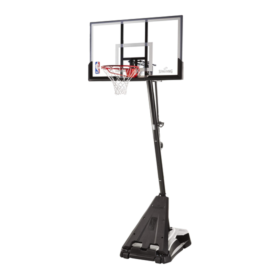
SICHERHEITSHINWEISE EIN MISSACHTEN DIESER SICHERHEITSHINWEISE KANN ZU SCHWEREN VERLETZUNGEN UND/ODER SACHSCHÄDEN FÜHREN UND MACHT DIE GARANTIE UNWIRKSAM. Der Eigentümer muss sicherstellen, dass alle Spieler diese Regeln für einen sicheren Betrieb des Systems kennen und befolgen. Aus Sicherheitsgründen darf dieses System nur unter sorgfältiger Beachtung der Anleitung zusammengebaut werden. - Seite 14 Get to know the basic parts of your basketball system... Apprenez à connaître les composants de base de votre système de basket-ball... Machen Sie sich mit den wichtigsten Teilen Ihres Basketballsystems vertraut… Conozca las piezas básicas de su sistema de baloncesto… FRONT VIEW BACK VIEW VUE DE DOS...
- Seite 15 PARTS LIST - See Hardware Identifier Item Qty. Part No. Description Item Qty. Part No. Description 600335 Base 205809 Bolt, Hex Head, 1/2-13 x 10.25 Long 901120 Strut, Left, Pole to Base 208251 Spacer, Plastic, 0.50 I.D. x 0.13 Long 901121 Strut, Right, Pole to Base 206340...
- Seite 16 LISTE DES PIÈCES - Voir légende Article Qté No. de réf. Description Article Qté No. de réf. Description 600335 Socle 205809 Boulon, tête à six pans, 1/2-13 x 10,25 (long.) 901120 Contrefiche, gauche, pôle de Base 208251 Entretoise, plastique, 0,50 D.I. x 0,13 901121 Contrefiche, droite, pôle de Base (long.)
- Seite 17 TEILELISTE – Siehe Teileschlüssel Anz. Teilenr. Beschreibung Anz. Teilenr. Beschreibung 600335 Sockel 205809 Sechskantkopfschraube, 1/2-13 x 10,25 lang 901120 Stütze, links, Stange zu Sockel 208251 Abstandsstück, Plastik, 0,50 ID x 0,13 lang 901121 Stütze, rechts, Stange zu Sockel 206340 Sechskant-Gegenmutter, 1/2-13 1 FR908418 Oberes Stangenteil (3,5”...
- Seite 18 LISTA DE PIEZAS - Vea el identificador de herraje Artículo Cant. Núm. Descripción Artículo Cant. Núm. Descripción 600335 Base 205809 Perno, cabeza hexagonal, 1/2-13 x 10,25 901120 Puntal, derecho, Poste a la Base de longitud 901121 Puntal, izquierdo, Poste a la Base 208251 Espaciador, plástico, 0,50 D.I.
- Seite 19 HARDWARE IDENTIFIER (BOLTS AND SCREWS) IDENTIFICATION DES PIÈCES (BOULONS & VIS) BEFESTIGUNGSTEILESCHLÜSSEL (BOLZEN UND SCHRAUBEN) IDENTIFICADOR DE HERRAJES (PERNOS Y TORNILLOS) #11 (1) #39 (2) #12 (1) 200520 - #8 x 3/4 Screw #18 (2) #26 (4) #23 (4) PN 205679 BOLT,HEX HD 1/2-13 X 2", 1.5” THREAD, ZINC PLTD #16 (2) #25 (2) #56 (2)
- Seite 20 HARDWARE IDENTIFIER IDENTIFICATION DES PIÈCES BEFESTIGUNGSTEILESCHLÜSSEL IDENTIFICADOR DE HERRAJES #36 (2) #30 (4) #49 (1) #50 (4) HARDWARE IDENTIFIER (OTHER) IDENTIFICATION DES PIÈCES (AUTRES) BEFESTIGUNGSTEILESCHLÜSSEL (SONSTIGE TEILE) IDENTIFICADOR DE HERRAJES (OTROS) #47 (1) #44 (1) #46 (1) #19 (1)
- Seite 21 SECTION A: ASSEMBLE THE BASE SECTION A : MONTAGE DU SOCLE BAUABSCHNITT A: ZUSAMMENBAU DES SOCKELS SECCIÓN A: MONTAJE DE LA BASE This is what your system will look like when you’ve finished this section. Voici à quoi ressemblera votre système lorsque vous en aurez fini avec cette section. So sieht das System aus, wenn Sie mit diesem Bauabschnitt fertig sind.
- Seite 22 Complete wheel assembly as shown in Figure A. Secure wheel bracket (7), wheel (8), axle (9), and push nuts (13) to the base (1) with a single bolt (18) and washer (24). Repeat procedure for opposite wheel. Terminer l’assemblage des roues comme indiqué dans la Figure A. Fixer le support de roue (7), la roue (8), l’essieu (9) et les écrous d’essieu (13) au socle (1) avec un seul boulon (18) et une rondelle (24).
- Seite 23 Correctly identify each pole section. Measure and mark a line, with marker or tape, 3 1/2 inches (9 cm) from the top of both the middle pole (5) and bottom pole (6). Correctement identifier chaque section de poteau. Mesurer et marquer une ligne, avec un marker ou un ruban adhésif, à...
- Seite 24 With a marker or tape measure, mark a line 3 1/2” (9 cm) from top end of middle pole (5). CAUTION While maintaining alignment, bounce middle pole (5) into top pole (4) using a wood scrap as ATTENTION ! shown until the top pole is aligned with the marked line on the middle pole. VORSICHT! You should have 3 1/2”...
- Seite 25 CAUTION With a marker or tape measure, mark a line 3 1/2” (9cm) from top end of bottom pole (6). ATTENTION ! Bounce top and middle pole assembly (4 and 5) onto bottom pole (6) using a wood scrap as shown.
- Seite 26 Attach pole assembly to base (1) as shown. Secure pole assembly to base using bolts (25) and pole mounting plate (19) as shown. Attacher les poteaux assemblés au socle (1) comme indiqué. Bien fixer l’ensemble au socle à l’aide de boulons (25) et de la plaque de fixation des poteaux (19) comme indiqué.
- Seite 27 Attach struts (2) and (3) to middle pole (5) with bolt (12), washer (24) and nut (10) as shown. Fixer les contrefiches (2) et (3) au poteau central (5) à l’aide d’un boulon (12), d’une rondelle (24) et d’un écrou (10) comme illustré.
- Seite 28 Rotate non-secured ends of base struts (2) and (3) to mounting holes in base as shown. Secure non-secured ends of base struts (2) and (3) to base with bolt (56) and washer (24). Tournez les extrémités non fixées des contrefiches du socle (2) et (3) vers les trous de fixation du socle, comme illustré. Fixez les extrémités des contrefiches (2) et (3) au socle à...
- Seite 29 Secure cover (21) to base struts (2) and (3) using bolts (22) and nuts (14) as shown. Fixez le couvercle (21) aux contrefiches du socle (2) et (3) à l’aide des boulons (22) et des écrous (14), comme illustré. Die Abdeckung (21) wie gezeigt mit den Schrauben (22) und Muttern (14) an den Sockelstreben (2) und (3) befestigen. Fije la cubierta (21) a los puntales la base (2) y (3) usando los pernos (22) y las tuercas (14) como se muestra.
- Seite 30 Install pole mount bracket (15) and reinforcement bracket (42) with carriage bolts (16) as shown. Tighten flange nuts (14) completely. Installez le support du poteau (15) et le support de renforcement (42) à l’aide des boulons ordinaires (16), comme illustré. Serrez à fond les écrous à bride (14). Die Stangenmontagehalterung (15) und die Verstärkungshalterung (42) wie gezeigt mit Schlossschrauben (16) befestigen.
- Seite 31 Securely rest the assembly on sawhorse. Identify elevator tubes (32 and 35). Posez l’ensemble sur un tréteau. Identifiez les tubes du système élévateur (32 et 35). Den Aufbau sicher auf dem Sägebock ablegen. Die Hubrohre (32 und 35) zurechtlegen. Apoye el conjunto en un caballete de manera segura. Identifique los tubos del elevador (32 y 35). WARNING! AVERTISSEMENT ! WARNUNG!
- Seite 32 While the system is securely resting on the sawhorse. Install elevator tubes (32 and 35) to top pole section (4) as shown. Install pole cap (38) at this time. Pendant que le système repose bien calé sur le tréteau, installez les tubes du système élévateur (32 et 35) sur la section de poteau supérieure (4), comme illustré.
- Seite 33 SECTION B: ATTACH THE BACKBOARD SECTION B : ATTACHEZ LE PANNEAU BAUABSCHNITT B: ANBRINGEN DER KORBWAND SECCIÓN B: COLOCACIÓN DEL TABLERO This is what your system will look like when you’ve finished this section. Voici à quoi ressemblera votre système lorsque vous aurez terminé cette section.
- Seite 34 While still supported on sawhorse. Attach elevator tubes (32, 35) to backboard using spacers (30), bolts (23), and nuts (31) as shown. Toujours sur le tréteau. Attachez les tubes du système élévateur (32, 35) au panneau à l’aide des entretoises (30), des boulons (23) et des écrous (31), comme illustré.
- Seite 35 Insert T-bolt (45) into Slam Jam bracket (44) then, attach that assembly to board using bolts (26) and nuts (14). Insérez le boulon en T (45) dans le support de Slam Jam (44), puis attachez l’ensemble au panneau à l’aide des boulons (26) et des écrous (14).
- Seite 36 Install Slam Jam Rim to Backboard Installez le cerceau Slam Jam sur le panneau Den Slam Jam-Korbrand an der Korbwand befestigen Instale el aro Slam Jam en el tablero NOTE: / REMARQUE : / HINWEIS: / NOTA: ORIENTATION OF BRACKET ORIENTATION DU SUPPORT AUSRICHTUNG DER HALTERUNG ORIENTACIÓN DEL SOPORTE...
- Seite 37 Install Slam Jam Rim to Backboard A. Fit rim (34) securely into bracket (44) as shown. Allow T-bolt (45) to slip through center hole in rim (34). B. Install reinforcement bracket (46) onto T-bolt (45) as shown. C. Install spring (47) onto T-bolt (45) as shown. D.
- Seite 38 COVER / COUVERCLE / ABDECKUNG / CUBIERTA Install cover (28) over spring return mechanism as shown. Installez le couvercle (28) sur le mécanisme de retour du ressort, comme illustré. Die Abdeckung (28) wie gezeigt über dem Rückfederungsmechanismus anbringen. Instale la cubierta (28) sobre el mecanismo de retorno por resorte como se muestra. Place cover (17) onto screw-jack assembly (55).
- Seite 39 Install handle assembly (55, 17 and 11) to lower elevator tubes (32) using bolt (29), spacers (36), and nut (31) as shown. Installez l’ensemble de la poignée (55, 17 et 11) sur les tubes inférieurs du système élévateur (32) en utilisant le boulon (29), les entretoises (36) et l’écrou (31), comme illustré.
- Seite 40 Secure the handle assembly (17) to pole bracket (15) using bolt (20) and nut (10) as shown. Fixez l’ensemble de la poignée (17) au support de poteau (15) à l’aide du boulon (20) et de l’écrou (10), comme illustré. Die Griffbaugruppe (17) mit Schraube (20) und Mutter (10) wie gezeigt an der Stangenhalterung (15) befestigen. Asegure el conjunto de la manija (17) en el soporte del poste (15) con el perno (20) y la tuerca (10) como se muestra.
- Seite 41 Roll completed assembly to desired position. Fill base with approximately 37 gallons (140 Liters) of water or approximately 400 lbs. (181 kg) sand and rotate the caps (41, 56) into base (1). Faites rouler l’ensemble jusqu’à la position désirée. Remplissez le socle de 37 gallons d’eau (140 litres environ) ou de 400 livres de sable (181 kg environ) et tournez les bouchons (41, 56) sur le socle (1).
- Seite 42 ATTENTION ! AVERTISSEMENT ! PAR MOINS DE 0 DEGRÉ CELSIUS, NE LAISSEZ PAS L’ASSEMBLAGE SANS AJOUTEZ DEUX GALLONS (7,6 LITRES) SUPERVISION LORSQU’IL EST VIDE, CAR D’ANTIGEL NON TOXIQUE. IL POURRAIT BASCULER. AVERTISSEMENT ! REMARQUE : Le bouchon (41) DOIT être BIEN serré À FOND pour éviter les fuites.
- Seite 43 NET INSTALLATION / INSTALLATION DU FILET / ANBRINGUNG DES NETZES / INSTALACIÓN DE LA RED Install net (43). / Installez le filet (43). / Das Netz (43) anbringen. / Instale la red (43). OUTSIDE VIEW / VUE EXTÉRIEURE / AUSSENANSICHT / VISTA EXTERNA Apply Height Adjustment and Moving Label (33) to front of pole, where it is clearly visible.
- Seite 44 SECTION C: BOARD PAD SECTION C : REMBOURRAGE DU PANNEAU ABSCHNITT C: KORBWANDPOLSTERUNG SECCIÓN C: ALMOHADILLA DEL TABLERO TOOLS REQUIRED FOR THIS SECTION OUTILS REQUIS POUR CETTE SECTION FÜR DIESEN BAUABSCHNITT BENÖTIGTES WERKZEUG HERRAMIENTAS REQUERIDAS PARA ESTA SECCIÓN 5/16” Flat-Head Screwdriver Socket Wrenches and Sockets ODER Un tournevis standard...
- Seite 45 TEILELISTE – Siehe Teileschlüssel Anz. Teilenr. Beschreibung Anz. Teilenr. Beschreibung 20157801 Korbwandpolsterung, linker Teil 205355 Bohreinsatz, 11/64 20157901 Korbwandpolsterung, rechter Teil 206303 Flache Unterlegscheibe, 1/4 201580 Korbwandpolsterung, mittlerer Teil Kappe, Schraubenabdeckung 202219 201596 Schraube, 1/4 x 1,25” Lang HINWEIS: Diesem Modell können zusätzliche Teile beigepackt sein. LISTA DE PIEZAS –...
- Seite 46 BOARD PAD / REMBOURRAGE DU PANNEAU KORBWANDPOLSTERUNG / ALMOHADILLA DEL TABLERO Using the holes which line up for your board size, attach Attach left and right pad sections to board using screws center pad section to left and right sections and board using and washers as shown.
- Seite 47 Using a 5/16 socket wrench or portable drill with a 5/16 socket attachment with the torque adjustment at the lowest setting, fasten the edge guards in place with the provided self-drilling, self-tapping screws (4). A l’aide d’une clé à douille 5/16 ou d’une perceuse portative munie d’une douille de 5/16, ajustez le couple de serrage en le plaçant sur le niveau le plus bas.
- Seite 48 APPLY HEIGHT INDICATOR DECALS FIXEZ LES ETIQUETTES AUTOCOLLANTES DU REPÈRE DE HAUTEUR HÖHENANZEIGE-AUFKLEBER ANBRINGEN APLIQUE LAS PEGATINAS INDICADORAS DE ALTURA Apply Height Indicator Labels (53) to screw jack using a tape measure. Tools needed for this operation - Tape measure, Step Ladder 8 ft.