Herunterladen Inhalt Inhalt Diese Seite drucken
Inhaltsverzeichnis

Werbung

Verfügbare Sprachen
  • DE

Verfügbare Sprachen

  • DEUTSCH, seite 1
CONVOTHERM mini OES 6.06
DE – Installationshandbuch
EN – Installation Manual
FR – Manuel d'installation
ES – Manual de instalacion
PT – Manual de instalação
IT – Manuale de installazione
NL – Installatiehandboek
Enodis

Werbung

Inhaltsverzeichnis
loading

Inhaltszusammenfassung für Convotherm mini OES 6.06

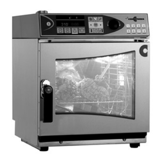
  • Seite 1 CONVOTHERM mini OES 6.06 DE – Installationshandbuch EN – Installation Manual FR – Manuel d’installation ES – Manual de instalacion PT – Manual de instalação IT – Manuale de installazione NL – Installatiehandboek Enodis...
  • Seite 2 Nuovi sviluppi tecnologici, cambiamenti ed errori attesi. Technische ontwikkelingen, wijzigingen en fouten voorbehouden. Enodis CONVOTHERM Elektrogeräte GmbH | Talstr. 35 | 82436 Eglfing (Germany) | Tel.: +49 (0) 88 47/67-0 | Fax +49 (0) 88 47/4 14 | info@convotherm.de | www.convotherm.de...
  • Seite 3: Inhaltsverzeichnis

    Deutsch 4 – 16 English 17 – 30 Français 31 – 44 Español 45 – 58 Português 59 – 72 Italiano 73 – 86 Nederlands 87 - 100 Declaration of Conformity...
  • Seite 4: Deutsch

    Sehr geehrter Kunde, Sie haben sich für einen OES 6.06 entschieden, herzlichen Dank für Ihr Vertrauen. Wir wünschen Ihnen viel Freude bei der Arbeit mit Ihrem Heißluftdämpfer! Allgemeine Information • Dieses Installationshandbuch gilt für den Heißluftdämpfer Typ OES 6.06 und dessen Varianten.
  • Seite 5 Inhaltsverzeichnis / Pictogramme Seite Inhalt Sicherheitshinweise Geräteanschluss (technisches Datenblatt) Aufstellung des Gerätes Elektroanschluss Wasseranschluss Wasserablauf Be- und Entlüftung Inbetriebnahme Umwelthinweis und Entsorgung Checkliste In diesem Installationshandbuch wurden nachfolgende Bildzeichen und Darstellungsarten als wichtige Sicherheitshinweise für den Installateur und teilweise den Anwender verwendet. Die Sicherheitshinweise, insbesondere die Warnungen, sind unbedingt zu beachten und zu be- folgen.
  • Seite 6: Sicherheitshinweise

    1. Sicherheitshinweise • Erhitzen Sie keine entflammbaren 1. Sicherheitshinweise Gegenstände, wie beispielsweise Öle, Fette, Tücher (Touchans) o.ä. im 1.1 Bestimmungsgemäße Verwen- Heißluftdämpfer. dung • Erhitzen Sie keine Nicht-Lebensmittel Funktionsbeschreibung (ausgenommen zugelassenes Geräte- • zubehör). In diesem Heißluftdämpfer darf der Bediener Lebensmittel garen. Hierzu 1.3 Sicherheitshinweise wird Dampf, Heißluft und Heißdampf Achtung Lebensgefahr...
  • Seite 7 1. Sicherheitshinweise Reinigung des Gerätes Reinigung des Gerätes • Tragen Sie bei Reinigungsarbeiten Schutzbrille und Schutzhandschuhe. • Nur vom Hersteller empfohlene Reinigungsmittel verwenden. • Beachten Sie die Sicherheitshinweise auf dem Reiniger und das zugehörige Sicherheitsdatenblatt! • Bei Verwendung von Reinigungsmitteln besteht die Gefahr von Gesundheits- schäden durch Verätzen der Lunge oder Haut.
  • Seite 8: Geräteanschluss (Technisches Datenblatt)

    2. Geräteanschluss 2. Geräteanschluss (technisches Datenblatt) A = Wasseranschluss C = Abwasseranschluss D = Elektroanschluss E = Potentialausgleich H = Entlüftungsrohr K = Belüftungsrohr...
  • Seite 9: Aufstellung Des Gerätes

    2. Geräteanschluss • Wasser: Trinkwasserqualität mit Aufstellung des Gerätes (vgl. Kapitel 2.1) Gesamthärte: 5-7°dH (Weichwasser) Geräteabmessungen: 6,5 bis 8,5 Leitwert: 10-200µS/cm Ohne max 100mg/l Verpackung Verpackung max 400mg/l max 0,1mg/l Breite 515 mm 580 mm max 0,05mg/l Tiefe 599 mm 730 mm max 0,05mg/l Höhe...
  • Seite 10 2. Geräteanschluss 2.1 Aufstellung des Gerätes • Gerät aufrecht transportieren! 50 mm • Geräteabmessung und -gewicht: 50 mm 50 mm Gerät mit 580 x 730 x 800 Verpackung: Gerät ohne 515 x 599 x 627 Verpackung: Gewicht ohne 45 kg Verpackung: •...
  • Seite 11: Elektroanschluss

    2. Geräteanschluss Reparatur- und Wartungsarbeiten den • Installieren Sie den Heißluftdämpfer Heißluftdämpfer bauseitig spannungs- nicht über Geräten mit einer starken frei schalten. Gefahr eines Strom- Wärme- und/oder Dampfabgabe, da schlags. dies die Funktion des Heißluftdämpfers • beeinträchtigen kann. Es besteht die Schalten Sie in Gerätenähe bauseitig Gefahr eines Stromschlages.
  • Seite 12: Wasseranschluss

    2. Geräteanschluss Elektro-Anschlussdaten 1/N/PE 3/N/PE Gesamthärte: 5-7°dH 230V 400V 6,5 bis 8,5 50/60Hz 50/60Hz Leitwert: 10-200µS/cm Anschlusswert [kW] max 100mg/l Leistung Heißluft [kW] max 400mg/l Leistung Motor [W] max 0,1mg/l 13,1 11,8 Nennstrom [A] max 0,05mg/l 3 x 2,5 5 x 2,5 Anschluss- max 0,05mg/l querschnitt* [mm²]...
  • Seite 13 2. Geräteanschluss 2.4 Wasserablauf 2.5 Be- und Entlüftung • Schließen Sie den Abwasseranschluss Für eine einwandfreie Funktion des Heiß- über einen offenen Ablauf (Trichter- luftdämpfers muss für einen kontinuierli- siphon) oder über einen Festanschluss chen Luftaustausch am Aufstellort gesorgt mit einem nicht flexiblen Rohr DN 40 werden.
  • Seite 14: Inbetriebnahme

    3. Inbetriebnahme 3. Inbetriebnahme • Die Umgebungstemperatur muss über 4°C liegen. • Nach Transport des Heißluftdämpfers bei Minustemperaturen, kann der Sicherheitstemperaturbegrenzer aus- gelöst haben. Führen Sie ein Reset des Sicherheitstemperaturbegrenzers an der Rückseite des Gerätes aus. • Stellen Sie das Manometer in der Wasserversorgung zur Dampfer- zeugung mit dem Druckregler auf einen Fließdruck von 110 kPa (1,1 bar)
  • Seite 15: Umwelthinweis Und Entsorgung

    3. Inbetriebnahme / 4. Umwelthinweis Einstellung c07, c08, c09 Version 1NPE in der Serviceebene Erklärung der Bedienschritte Bedienschritte Displayanzeige 1. Tasten Temperatur + Zeit + KTM r01 [ 22°C ] KTM1 für 3 Sekunden gleichzeitig r02 [ 23°C ] KTM2 drücken r03 [ 23°C ] KTM3...
  • Seite 16: Checkliste

    5. Checkliste Wir empfehlen Ihnen zum Nachweis der korrekten Installation eines Heißluftdämpfers und der erfolgten Einweisung des Kunden die Checkliste auszufüllen, abzeichnen zu lassen und zu dokumentieren. Standort des installierten Gerätes: __________________________________________________________ Gerätenummer (vgl. Typenschild):__________________________________________________________ Artikelnummer (vgl. Typenschild): __________________________________________________________ Aufstellung Ist der Heißluftdämpfer waagerecht, kippsicher und rutschsicher aufgestellt? Sind die Sicherheitsabstände links, rechts, hinten 50 mm sowie oben, Wärmequelle 500 mm eingehalten?
  • Seite 17: English

    English...
  • Seite 18: Warranty Conditions

    Dear Customer, Thank you for your confidence in choosing an OES 6.06. We hope you enjoying working with your combi steamer! General Information • This installation manual is for the combi steamer model OES 6.06 and its variants. With special models observe the additional information. •...
  • Seite 19 Table of Contents / Pictograms Page Contents Safety Instructions Unit Connection (technical data sheet) Positioning the unit Connecting to the electrical supply Connecting to the water supply Drainage connection Ventilation Commissioning Environmental Information and Disposal Checklist The following pictorial markings and methods of representation have been used in this installation manual as safety notices for the installer and in some cases for the user.
  • Seite 20: Safety Instructions

    1. Safety Instructions 1.3 Safety instructions 1. Safety instructions Attention danger to life 1.1 Use as prescribed Installation and maintenance Function description • Before opening the housing cover and • The operator can cook food in this carrying out repair and maintenance combi steamer.
  • Seite 21 1. Safety Instructions Cleaning the unit Cleaning the unit • Wear protective goggles and gloves when cleaning. • Only use cleaning agents recommended by the manufacturer. • Observe the safety instructions on the cleaner and the accompanying safety data sheet! •...
  • Seite 22: Unit Connection (Technical Data Sheet)

    2. Unit Connection 2. Unit Connection (technical data sheet) A = Water connection C = Drainage connection D = Electrical connection E = Potential equalisation H = Vent pipe K = Air inlet pipe...
  • Seite 23 2. Unit Connection Positioning the unit Water connection (A) (cf. Chapter 2.1) (cf. Chapter 2.3) • Cold water ¾“ 2 to 6 bar flow pressure Unit dimensions: • Water tap and filter are to be installed by Without With the customer in the vicinity of the unit packaging packaging •...
  • Seite 24: Positioning The Unit

    2. Unit Connection 2.1 Positioning the unit • Transport unit in an upright position! 50 mm • Unit dimensions and weight: 50 mm 50 mm Unit + packaging: 580 x 730 x 800 Unit without 515 x 599 x 627 packaging: Weight without 45 kg (99.2 lbs)
  • Seite 25: Connecting To The Electrical Supply

    2. Unit Connection • In the vicinity of the unit, connect an • Do not install the combi steamer above accessible all pole separator with a units which give off a lot of heat and/or contact gap of at least 3 mm, which steam, as this can affect how the must be used to switch off the electrical combi steamer functions.
  • Seite 26: Connecting To The Water Supply

    2. Unit Connection Electrical connection data 1/N/PE 3/N/PE Total 5-7°dH 230V 400V hardness: 50/60 Hz 50/60 Hz 6.5 to 8.5 Connected load [kW] Conductivity: 10-200µS/cm Convection output max 100mg/l [kW] max 400mg/l Motor output [W] max 0.1mg/l 13,1 11,8 Rated current [A] max 0.05mg/l Connection cross- 3 x 2.5...
  • Seite 27: Drainage Connection

    2. Unit Connection 2.5 Ventilation 2.4 Drainage connection For trouble-free functioning of the combi • The run-off water can be connected via steamer, a regular air exchange must be an open drain (funnel siphon) or via a provided in the place the unit is being fixed connection with a non-flexible DN operated.
  • Seite 28: Commissioning

    3. Commissioning 3. Commissioning • The ambient temperature must be above 4°C. • After the combi steamer has been transported at minus temperatures, the safety temperature limiter might have triggered. Carry out a reset of the safety temperature limiter on the rear side of the unit.
  • Seite 29: Environmental Information And Disposal

    3. Commissioning / 4. Environmental Information Setting c07, c08, c09 Version 1NPE in the service level User action explanation User action Display 1. Hold down temperature + time + r01 [ 22°C ] CTC1 KTM keys for 3 seconds r02 [ 23°C ] CTC2 simultaneously r03 [ 23°C ]...
  • Seite 30: Checklist

    5. Checklist As proof of the correct installation of a combi steamer and the subsequent customer briefing we recommend that you fill out the checklist and have it copied and documented. Location of the installed unit: ______________________________________________________________ Unit number (cf. Type label): ____________________________________________________________________ Article number (cf.
  • Seite 31: Français

    Français...
  • Seite 32: Informations Générales

    Cher Client, Nous vous remercions vivement d’avoir choisi le modèle OES 6.06. Nous vous souhaitons un travail très agréable avec votre four mixte ! Informations générales • Ce manuel d’installation concerne le four mixte OES 6.06 et ses variantes. Tenez compte des informations complémentaires accompagnant les séries spéciales.
  • Seite 33 Table des matières / Pictogramme Page Table des matières Consignes de sécurité Branchement de l‘appareil (fiche de données techniques) Mise en place Branchement électrique Raccordement hydrique Evacuation de l'eau Aération et ventilation Mise en marche Ecologie et mise au rebut Liste des contrôles Les symboles et modes de représentation suivants ont été...
  • Seite 34: Consignes De Sécurité

    1. Consignes de sécurité • Ne chauffez pas dans le four mixte des 1. Consignes de sécurité objets inflammables comme, par exemple, des huiles, des graisses, des 1.1 Utilisation conforme chiffons. Description de la fonction • Ne chauffez pas de substances non •...
  • Seite 35 1. Consignes de sécurité normes et des dispositions en vigueur dans chaque pays. Nettoyage de l’appareil • Pendant les opérations de nettoyage, portez des lunettes de protection ainsi que des gants. • N’utilisez que les produits de nettoyage préconisés par le fabricant. •...
  • Seite 36: Branchement De L'appareil (Fiche De Données Techniques)

    2. Branchement de l’appareil 2. Branchement de l‘appareil (fiche de données techniques) A = raccordement hydrique C = raccordement pour les eaux usées D = branchement électrique E = stabilisation du potentiel H = tuyau de ventilation K = tuyau d’aération...
  • Seite 37 2. Branchement de l’appareil Mise en place Raccordement hydrique (A) (cf. chapitre 2.1) Dimensions de l’appareil : (cf. chapitre 2.3) • Pression de circulation de l’eau froide ¾“ de 2 à 6 bars Sans Avec • Il faut prévoir un robinet d’eau et un emballage emballage tamis à...
  • Seite 38: Mise En Place

    2. Branchement de l’appareil 2.1 Mise en place • Transporter l’appareil en position 50 mm verticale ! • Dimensions et poids de l’appareil : 50 mm 50 mm Appareil avec 580 x 730 x 800 emballage : Appareil sans 515 x 599 x 627 emballage : Poids sans 45 kg...
  • Seite 39: Branchement Électrique

    2. Branchement de l’appareil le four mixte hors tension. Danger • Ne stockez pas et n'utilisez pas de gaz d’électrocution. ou liquides inflammables à proximité • de l'appareil. Ceux-ci risqueraient de A proximité de l'appareil, branchez un prendre feu suite au dégagement de sectionneur omnipolaire facilement chaleur de l'appareil, ce qui s'avérerait accessible avec ·une ouverture de...
  • Seite 40: Raccordement Hydrique

    2. Branchement de l’appareil Spécifications du branchement électrique Dureté totale : 5-7°dH 1/N/PE 3/N/PE pH : 6,5 à 8,5 230V 400 V Conductance : 10-200 µS/cm 50/60 Hz 50/60 Hz max 100mg/l Puissance raccordée [kW] max 400mg/l Puissance air pulsé [kW] max 0,1mg/l Fe : Puissance moteur [W]...
  • Seite 41: Evacuation De L'eau

    2. Branchement de l’appareil 2.5 Aération et ventilation 2.4 Evacuation de l'eau Pour que le four mixte fonctionne • Effectuez le raccordement au réseau parfaitement, il faut garantir un échange des eaux usées au moyen d’un d’air constant dans le local où il est dispositif d’évacuation ouvert (siphon installé.
  • Seite 42: Mise En Marche

    3. Mise en marche • Réglez le programme de cuisson air 3. Mise en marche mixte sur 150°C, 10 minutes et effectuez les contrôles suivants : • La température ambiante doit être supérieure à 4°C. - L’éclairage de l’enceinte de cuisson est-il allumé...
  • Seite 43: Ecologie Et Mise Au Rebut

    3. Mise en marche / 4. Ecologie Réglage c07, c08, c09 Version 1NPE dans le niveau de service Explication des cycles d’utilisation Cycles d’utilisation Affichage 1. Appuyez simultanément sur les r01 [ 22°C ] sonde1 touches Température + Heure + r02 [ 23°C ] sonde2 KTM pendant 3 secondes...
  • Seite 44: Liste Des Contrôles

    5. Liste de contrôles Nous vous conseillons de remplir, de faire signer et de documenter la liste de contrôles afin de certifier que le four mixte a été installé dans les règles de l’art et que le client a bien été initié à son fonctionnement. Lieu d’installation de l’appareil : ____________________________________________________________ Numéro de matricule de l’appareil (cf.
  • Seite 45: Español

    Español...
  • Seite 46 Estimado cliente: Le agradecemos la confianza depositada al adquirir una unidad OES 6.06. Le deseamos que disfrute trabajando con su vapor mixto. Información general • Este manual de instalación se refiere al vapor mixto OES 6.06 y sus variantes. En caso de disponer de un modelo especial, consulte la información adicional.
  • Seite 47 índice / pictograma Página Índice Indicaciones de seguridad Conexión del aparato (hoja de datos técnicos) Instalación del aparato Conexión eléctrica Suministro de agua Desagüe Entada y salida de aire Puesta en funcionamiento Indicaciones medioambientales y eliminación de desechos Lista de comprobación En este manual de instalación se incluyen los siguientes símbolos y representaciones gráficas como indicaciones de seguridad importantes para el instalador y el usuario.
  • Seite 48: Indicaciones De Seguridad

    1. Indicaciones de seguridad • Caliente alimentos únicamente 1. Indicaciones de seguridad (excepto los accesorios homologados del aparato). 1.1 Uso correcto 1.3 Indicaciones de seguridad Descripción del funcionamiento Peligro de muerte • El usuario puede cocer alimentos en Instalación y mantenimiento este vapor mixto.
  • Seite 49 1. Indicaciones de seguridad Limpieza del aparato • Para realizar las tareas de limpieza, utilice gafas y guantes de seguridad. • Emplee únicamente productos de limpieza recomendados por el fabricante. • Observe las indicaciones de seguridad del producto de limpieza y de la hoja de datos de seguridad suministrada.
  • Seite 50: Conexión Del Aparato

    2. Conexión del aparato 2. Conexión del aparato (hoja de datos técnicos) A = Suministro de agua C = Desagüe D = Conexión eléctrica E = Conexión equipotencial H = Conducto de salida de aire K = Conducto de ventilación...
  • Seite 51: Instalación Del Aparato

    2. Conexión del aparato Instalación del aparato Suministro de agua (A) (consulte el capítulo 2.1) (consulte el capítulo 2.3) Dimensiones del aparato: • Fluopresión del agua fría de 2 a 6 bar (racor de ¾"). • El grifo del agua y el depurador de residuos debe instalarse en la embalaje embalaje...
  • Seite 52 2. Conexión del aparato 2.1 Instalación del aparato • Transporte el aparato en posición 50 mm vertical. • Dimensiones y peso del aparato: 50 mm 50 mm Aparato con 580 x 730 x 800 embalaje: Aparato sin 515 x 599 x 627 embalaje: Peso sin 45 kg...
  • Seite 53: Conexión Eléctrica

    2. Conexión del aparato • Antes de abrir la pared lateral y • Nunca instale el vapor mixto sobre ejecutar trabajos de reparación y aparatos con salida de calor y/o vapor mantenimiento, desconecte el vapor intensa, ya que puede afectar al mixto de la tensión de red.
  • Seite 54: Suministro De Agua

    2. Conexión del aparato • Antes de la puesta en servicio, Dureza total: 5-7 dH compruebe la firmeza de todos los 6,5 a 8,5 tornillos y terminales de unión. Existe el riesgo de que se aflojen durante el Conductancia: 10-200 µS/cm transporte.
  • Seite 55 2. Conexión del aparato 2.5 Entrada y salida de aire 2.4 Desagüe Para el correcto funcionamiento del vapor • Conecte la conexión de desagüe a mixto, es preciso que el lugar de través de un canal de desagüe abierto instalación disponga de ventilación (sifón de tolva) o de una toma fija con continua.
  • Seite 56: Puesta En Funcionamiento

    3. Puesta en funcionamiento • Seleccione el programa de cocción de 3. Puesta en funcionamiento vapor caliente a 150 °C durante 10 minutos como mínimo y controle lo • La temperatura ambiente debe ser siguiente: superior a 4 °C. - ¿Se enciende la luz de la cámara •...
  • Seite 57 3. Puesta en funcionamiento 4. Indicaciones medioambientales Configuración c07, c08, c09 de la versión 1NPE en el nivel de servicio Descripción de los pasos de Pasos de funcionamiento Indicación de pantalla funcionamiento 1. Pulse las teclas Temperatura + r01 [ 22°C ] Sonda1 Hora + KTM simultáneamente r02 [ 23°C ] Sonda2 durante 3 segundos...
  • Seite 58: Lista De Comprobación

    5. Lista de comprobación Para determinar la correcta instalación de un vapor mixto y su entrega al cliente, rellene y firme la lista de comprobación. Emplazamiento del aparato instalado: _______________________________________________________ Número de aparato (consulte la placa de características): _______________________________________ Número de elemento (consulte la placa de características): ______________________________________ Sí...
  • Seite 59: Português

    Português...
  • Seite 60 Caro cliente, Gostaríamos de agradecer a sua preferência pelo OES 6.06 e pela confiança depositada na nossa empresa. Esperamos que fique satisfeito com o seu forno convector misto e desejamos-lhe bons cozinhados! Informações Gerais • O presente Manual de Instalação é válido para o forno convector misto, modelo OES 6.06, e respectivas variantes.
  • Seite 61 Índice / Pictogramas Página Índice Instruções de segurança Ligação do aparelho (especificações técnicas) Especificações do aparelho Ligação à electricidade Ligação de água Escoamento de água Sistema de ventilação Colocação em funcionamento Aspectos ambientais e eliminação Lista de verificação No presente Manual de Instalação foram utilizados os seguintes pictogramas e representações gráficas como instruções de segurança para o canalizador e, parcialmente, para o utilizador.
  • Seite 62: Instruções De Segurança

    1. Instruções de segurança • Não aquecer objectos inflamáveis, 1. Instruções de segurança como por exemplo: óleos, gorduras, toalhas, entre outros, no forno. 1.1 Utilização normal • Não aquecer produtos não alimentares Descrição do funcionamento (excepto acessórios do aparelho • Neste forno convector misto o permitidos).
  • Seite 63 1. Instruções de segurança as normas e regulamentos em vigor no país em questão. Limpeza do aparelho • Utilizar óculos e luvas de protecção durante os trabalhos de limpeza. • Utilizar apenas os detergentes recomendados pelo fabricante. • Ter em atenção as instruções de segurança constantes do detergente e a respectiva folha de dados de segurança!
  • Seite 64: Ligação Do Aparelho

    2. Ligação do aparelho 2. Ligação do aparelho (especificações técnicas) A = ligação de água C = ligação ao esgoto D = ligação à electricidade E = equalização de potencial H = tubo de ventilação K = tubo de arejamento...
  • Seite 65: Especificações Do Aparelho

    2. Ligação do aparelho Ligação de água (A) Especificações do aparelho (consultar a secção 2.3) (consultar a secção 2.1) • Água fria ¾“ 2 até uma pressão de fluxo Dimensões do aparelho: máxima de 6 bar • A torneira e o filtro devem ser instalados na proximidade do aparelho pelo cliente embalagem embalagem...
  • Seite 66 2. Ligação do aparelho 2.1 Especificações do aparelho • Transportar o aparelho na posição 50 mm vertical! • Dimensões e peso do aparelho: 50 mm 50 mm Aparelho com 580 x 730 x 800 embalagem: Aparelho sem 515 x 599 x 627 embalagem: Peso sem 45 kg...
  • Seite 67: Ligação À Electricidade

    2. Ligação do aparelho eléctrica; a chapa de identificação • Não instalar o forno convector misto encontra-se na lateral do aparelho. sobre aparelhos com uma elevada • Antes da abertura da cobertura da caixa emissão de calor e/ou vapor, uma vez e da execução de trabalhos de que o funcionamento do forno reparação e manutenção, o cliente...
  • Seite 68: Ligação De Água

    2. Ligação do aparelho • Verificar a fixação de todas as uniões • A água deverá apresentar as seguintes roscadas e de aperto na câmara de características: ligação antes da colocação em Água fria com qualidade de água funcionamento. Perigo de potável (água doce) afrouxamento devido ao transporte.
  • Seite 69 2. Ligação do aparelho 2.4 Escoamento de água 2.5 Sistema de ventilação • Conectar a ligação de água através de Para um funcionamento perfeito do forno um canal de drenagem aberto (sifão convector misto, deve garantir-se a em cone) ou de uma ligação fixa com ventilação permanente no local de um tubo flexível DN 40.
  • Seite 70: Colocação Em Funcionamento

    3. Colocação em funcionamento • Regular o programa de cozedura 3. Colocação em “vapor sobreaquecido” para 150 °C, 10 funcionamento min., e controlar o seguinte: - A iluminação da câmara de cozedura • A temperatura ambiente deverá ser está ligada? superior a 4°C.
  • Seite 71 3. Colocação em funcionamento / 4. Aspectos ambientais Ajuste c07, c08, c09 versão 1NPE no nível de serviço Explicação dos passos de comando Passos de comando Indicação no display 1. Premir simultaneamente as teclas r01 [ 22°C ] Sensor central 1 temperatura + tempo + KTM r02 [ 23°C ] Sensor central 2 durante 3 segundos...
  • Seite 72: Lista De Verificação

    5. Lista de Verificação Recomendamos que a Lista de Verificação seja preenchida, assinada e documentada, para comprovar a correcta instalação de um forno convector misto e das instruções do cliente. Local de instalação do aparelho: _______________________________________________________ Número do aparelho (ver chapa de identificação): _________________________________________ Número do artigo (ver chapa de identificação): ____________________________________________ Sim! Instalação...
  • Seite 73: Italiano

    Italiano...
  • Seite 74: Informazioni Generali

    Gentile Cliente, Grazie per aver scelto un OES 6.06 e per la fiducia dimostrata. Le auguriamo buon lavoro con il Suo forno misto a termoconvezione/vapore! Informazioni generali • Il presente manuale di installazione vale per il forno a termoconvezione /vapore Mod. OES 6.06 e le sue varianti.
  • Seite 75 Indice / Pittogrammi Pagina Indice Avvertenze di sicurezza Collegamento dell’apparecchio (scheda tecnica) Montaggio dell’apparecchio Collegamento elettrico Allacciamento acqua Scarico dell’acqua Aerazione e sfiato Messa in servizio Avvertenze ecologiche e smaltimento Lista di controllo Nel presente manuale di installazione si utilizzano i seguenti simboli e tipi di segnalazione come avvertenze di sicurezza importanti per l'installatore e anche per l'utilizzatore.
  • Seite 76: Avvertenze Di Sicurezza

    1. Avvertenze di sicurezza • Non riscaldare oggetti infiammabili 1. Avvertenze di sicurezza quali oli, grassi, o fazzoletti (Touchans) o altro nel forno misto a 1.1 Uso proprio termoconvezione/vapore. • Non riscaldare oggetti diversi dagli Descrizione del funzionamento alimenti (eccetto gli accessori ammessi •...
  • Seite 77 1. Avvertenze di sicurezza • Azionamento Non riscaldare mai i detergenti per forni commerciali o i loro residui per Per evitare incidenti ed eventuali danni al • evitare il pericolo di corrosione. forno misto a termoconvezione/vapore, l’operatore deve addestrare regolarmente il personale. L’apparecchio può...
  • Seite 78: Collegamento Dell'apparecchio

    2. Collegamento dell’apparecchio 2. Collegamento dell’apparecchio (scheda tecnica) A = Attacco acqua C = Attacco acqua di scarico D = Collegamento elettrico E = Compensazione equipotenziale. H = Tubo di sfiato K = Tubo di aerazione...
  • Seite 79: Montaggio Dell'apparecchio

    2. Collegamento dell’apparecchio Montaggio dell’apparecchio Allacciamento acqua (A) (crf. capitolo 2.1) (cfr. capitolo 2.3) • Raccordo da ¾“ per acqua fredda, da 2 Dimensioni dell’apparecchio: a 6 bar di pressione di flusso • Il rubinetto dell’acqua e il filtro per i Senza residui devono essere installati a parte imballaggio...
  • Seite 80 2. Collegamento dell’apparecchio 2.1 Montaggio dell’apparecchio 50 mm • Trasportare l’apparecchio diritto! • Dimensioni e peso dell’apparecchio: 50 mm 50 mm Apparecchio con 580 x 730 x 800 imballaggio: Apparecchio senza 515 x 599 x 627 imballaggio: Peso senza 45 kg imballaggio: •...
  • Seite 81: Collegamento Elettrico

    2. Collegamento dell’apparecchio di identificazione è situata sul lato • Non installare il forno misto a dell’apparecchio. termoconvezione/vapore con una forte • perdita di calore e/o di vapore, poiché Prima di aprire la copertura ciò potrebbe compromettere il dell’alloggiamento e dell’esecuzione di funzionamento del forno misto a interventi di manutenzione e di termoconvezione/vapore.
  • Seite 82: Allacciamento Acqua

    2. Collegamento dell’apparecchio • • Il pressacavo serve per allentare la Informarsi sulla qualità e la durezza trazione e deve essere fissato dell’acqua presso l’azienda di fermamente. erogazione dell’acqua locale. • • Controllare tutti i pressacavi e i L’acqua deve presentare le seguenti morsetti nel vano dei collegamenti caratteristiche: prima della messa in servizio per...
  • Seite 83: Scarico Dell'acqua

    2. Collegamento dell’apparecchio 2.4 Scarico dell’acqua 2.5 Aerazione e sfiato • Per un perfetto funzionamento del forno Chiudere il raccordo di scarico misto a termoconvezione/vapore si deve dell'acqua mediante uno scarico aperto assicurare uno scambio continuo dell’aria (sifone ad imbuto) oppure un raccordo nella sede di montaggio.
  • Seite 84: Messa In Servizio

    3. Messa in servizio • Impostare il programma di cottura 3. Messa in servizio “Termoconvezione/vapore“ a 150°C, per 10 min e controllare quanto segue: • La temperatura ambiente deve essere - La luce della camera di cottura è superiore a 4°C. accesa? •...
  • Seite 85: Avvertenze Ecologiche E Smaltimento

    3. Messa in servizio / 4. Avvertenze ecologiche Regolazioni c07, c08, c09, versione 1NPE nel programma di manutenzione Spiegazione delle operazioni Operazioni Visualizzazione sul display 1. Premere contemporaneamente i r01 [ 22°C ] STC1 tasti Temperatura + Tempo + KTM r02 [ 23°C ] STC2 per 3 secondi...
  • Seite 86: Lista Di Controllo

    5. Lista di controllo Raccomandiamo come prova della corretta installazione del forno misto a termoconvezione/vapore e dell’addestramento eseguito con esito positivo del cliente di compilare la seguente lista di controllo, di farla firmare e documentare. Sede dell’apparecchio installato: ___________________________________________________ Numero di serie dell’apparecchio (cfr. targhetta di identificazione):_________________________ Numero dell’articolo (cfr.
  • Seite 87: Nederlands

    Nederlands...
  • Seite 88: Garantiebepalingen

    Geachte klant, U hebt voor een OES 6.06 gekozen, hartelijk dank voor uw vertrouwen. We wensen u veel plezier met het gebruik van uw heteluchtoven! Algemene informatie • Deze installatiehandleiding geldt voor de heteluchtoven van het type OES 6.06 en zijn varianten.
  • Seite 89 Inhoudsopgave / Pictogrammen Pagina Inhoudsopgave Veiligheidsaanwijzingen Installatie van het apparaat (technische gegevens) Plaatsing van het apparaat Aansluiting van het elektra Aansluiting van het water Afwatering Ventilatie Ingebruikname Milieutips en afdanking Checklist In deze installatiehandleiding worden de volgende pictogrammen en afbeeldingen als belangrijke veiligheidsaanwijzingen gebruikt voor de installateur en deels voor de gebruiker.
  • Seite 90: Veiligheidsaanwijzingen

    1. Veiligheidsaanwijzingen • Verhit geen ontvlambare voorwerpen 1. Veiligheidsaanwijzingen zoals olie, vet, doeken (tissues) e.d. in de heteluchtoven. 1.1 Voorgeschreven gebruik • Verhit niet-levensmiddelen niet in de Functiebeschrijving oven (met uitzondering van de • In deze heteluchtoven kan de toegestane apparaataccessoires). gebruiker levensmiddelen bereiden.
  • Seite 91 1. Veiligheidsaanwijzingen afhankelijk van de landelijk geldende normen en voorschriften. Reiniging van het apparaat • Draag bij reinigingswerkzaamheden een beschermbril en beschermende handschoenen. • Gebruik alleen de door de fabrikant aanbevolen reinigingsmiddelen. • Neem de veiligheidsaanwijzingen op de verpakking van het reinigingsmiddel en het bijbehorende veiligheidsinformatieblad in acht.
  • Seite 92: Installatie Van Het Apparaat (Technische Gegevens)

    2. Installatie van het apparaat 2. Installatie van het apparaat (technische gegevens) A = Wateraansluiting C = Aansluiting afwatering D = Aansluiting van het elektra E = Potentiaaluitlijning H = Ontluchtingsbuis K = Beluchtingsbuis...
  • Seite 93: Plaatsing Van Het Apparaat

    2. Installatie van het apparaat Aansluiting van het water (A) Plaatsing van het apparaat (zie Hoofdstuk 2.1) (zie Hoofdstuk 2.3) Afmetingen van het apparaat: • Koud water ¾“ 2 tot 6 bar stroomdruk • Waterkraan en vuilfilter moeten door de Zonder klant in de nabijheid van het apparaat verpakking...
  • Seite 94: Plaatsing Van Het Apparaat

    2. Installatie van het apparaat 2.1 Plaatsing van het apparaat • Apparaat rechtop vervoeren! 50 mm • Afmetingen en gewicht van het apparaat 50 mm 50 mm Apparaat met 580 x 730 x 800 verpakking Apparaat zonder 515 x 599 x 627 verpakking: Gewicht zonder 45 kg...
  • Seite 95 2. Installatie van het apparaat • Alvorens de behuizingsafdekking te • Installeer de heteluchtoven niet boven openen en reparatie- en apparaten met een sterke warmte- onderhoudswerkzaamheden te en/of stoomafgifte, aangezien dit het verrichten, de heteluchtoven functioneren van de heteluchtoven kan uitschakelen en de stekker uit het beinvloeden.
  • Seite 96 2. Installatie van het apparaat • Controleer alle schroef- en totale hardheid: 5-7°dH klemverbindingen in de aansluitruimte 6,5 tot en met 8,5 op bevestiging vóór de ingebruikname. Er bestaat gevaar op blokkering door Geleidbaarheid: 10-200µS/cm het vervoer. Cl-: max 100mg/l max 400mg/l Gegevens voor de aansluiting van de max 0,1mg/l...
  • Seite 97: Afwatering

    2. Installatie van het apparaat 2.4 Afwatering 2.5 Ventilatie • Sluit de afwateringsaansluiting via een Voor een foutloos functioneren van de open afvoer aan (trechtersifon) of via heteluchtoven met voor een continue een vaste aansluiting met een niet- luchtuitwisseling op de plaatsingslocatie flexibele buis DN 40.
  • Seite 98: Ingebruikname

    3. Ingebruikname 3. Ingebruikname • De omgevingstemperatuur moet hoger zijn dan 4°C. • Na vervoer van de heteluchtoven bij minimumtemperaturen kan de veiligheidstemperatuurbegrenzer gewist zijn. U kunt de temperatuurbegrenzer resetten aan de achterkant van het apparaat. • Stel de manometer van de watervoorziening voor de stoomafzuiging in op een stroomdruk van 110 kPA (1,1 bar) met de...
  • Seite 99: Milieutips En Afdanking

    3. Ingebruikname / 4. Milieutips en afdanking Instelling op servicevlak van c07, c08, c09, versie 1NPE Verklaring van de Bedieningsstappen Weergave op display bedieningsstappen 1. Knoppen temperatuur + tijd + KTM r01 [ 22°C ] kern sensor 1 3 seconden lang gelijktijding r02 [ 23°C ] kern sensor 2 indrukken.
  • Seite 100: Checklist

    5. Checklist We raden u aan ter aantoning van de juiste installatie van de heteluchtoven en de opgevolgde instructie van de klant de checklist in te vullen, te laten ondertekenen en te archiveren. Plaats van het geïnstalleerde apparaat:______________________________________________________ Apparaatnummer (zie typeplaatje): _________________________________________________________ Artikelnummer (zie typeplaatje):____________________________________________________________ Plaatsing Is de heteluchtoven horizontaal, kiepvrij en slipvrij geplaatst? Zijn de veiligheidsafstanden voor...
  • Seite 101: Konformitätserklärung Declaration Of Conformity

    DIN EN ISO 9001 und ein zertifiziertes Umweltmanagement-System nach DIN EN ISO 14001 an. CONVOTHERM Elektrogeräte GmbH is maintaining a quality system which meets the requirements of DIN EN ISO 9001 and the consideration of environmental recommendations according to DIN EN ISO 14001 Eglfing, den 27.06.2006...
  • Seite 102 Notes ........................................................................................................................................................................................................................................................................................................................................................................................................................................................................................................................................................................................................................................................................................................................................................................................................................................................................................................................................................................................

Inhaltsverzeichnis