Seite 1
StecaGrid 20 000 StecaGrid 23 000 Installation and operating instructions Installations- und Bedienungsanleitung Istruzioni d'installazione e d'uso EN DE IT 748.508 | Z01 | 2013-06-10...
Table of Contents 0 B Regarding these operating instructions................. 4 Symbols and markings ....................4 Warning notices ......................4 1.2.1 Layout of a warning notice....................4 1.2.2 Categories of warning notices ..................4 Notices ..........................5 Safety notices..........................6 Proper usage ........................6 Qualification of personnel ....................
Seite 4
4.14 Interface Port RS485 ....................25 4.15 Ethernet ........................26 Commissioning ........................27 Turn on the Device......................27 Setting the Country Code and the Menu Language ............. 28 Activating the Device ....................30 Navigation on the Control Panel ................... 32 Password Entry......................
Regarding these operating instructions The operating instructions form a part of the product Read the operating instructions before using the product. Keep the operating instructions readily available with the device for the entire life expec- tancy of the product. ...
"WARNING" designates a safety notice, disregarding which can lead to death or severe bodily injury being sustained! WARNING "CARE" designates a safety notice, disregarding which can lead to material damage or light bodily injuries being sustained! CARE 1.3 Notices Notice: A notice describes information which is important for the optimum and cost-effective operation of the equipment.
Safety notices 2.1 Proper usage The StecaGrid 20000 3ph and StecaGrid 23000 3ph, referred to in these operating instructions as the inverter, is a solar inverter, which transforms the direct current generated by the PV generator (photovoltaic modules) into alternating current and feeds this to the public power supply network. The inverter has been constructed according to the current state of technology and in line with the rules of technical safety.
Danger to health for persons with pace-makers, metallic implants and hearing aids in direct proximity to electrical equipment. Corresponding circle of persons must consult their doctor before- hand. WARNING Danger of burns! Machine housing surfaces may be hot! Allow hot surfaces to cool down. WARNING Danger of bodily injury through crushing, shearing, cutting, striking.
2.5 Protection against magnetic & electro-magnetic fields during operation & assembly Danger to health for persons with pace-makers, metallic implants and hear- ing aids in direct proximity to electrical equipment. Persons with pace-makers and metallic implants must not as a rule enter areas in which electrical devices and parts are being assembled, oper- ated or are being brought into service.
2.7 Protection during handling and assembly Danger of injury with improper handling through crushing, shearing, cut- ting, striking and raising. The weight of the inverter amounts to 40 kg! Follow the general instructions for assembly and safety whilst handling and setting up.
The inverter complies with the RoHS Directive. That means that the device can be delivered to local sites for the disposal of household appliances. Steca takes the inverter completely back. Please contact the Ser- vice! 748.508 | Z01 | 2013-06-10...
Description of StecaGrid 20000 3ph and 23000 3ph 3.1 Description of the Inverter The StecaGrid 20000 3ph and 23000 3ph is a three-phase solar inverter without a transformer, which has a particularly high efficiency at any operating point and is suitable for the connection of a PV generator with a power of 21.6 kW and 25.8 kW.
3.2 Scope of Delivery The scope of delivery includes a wall-mounting bracket and an enclosed bag 0030532 containing: 1 x 5-pin contact insert, IP67, VC-TFS5-PEA 1 x adapter housing, IP67, VC-K-T3-R-M25-PLOMB 3 x U-washer, shape B, M8, DIN125-8 1 x cable gland, Schlemmer-Tec, M25x1.5/21532 2 x cross-recessed flat-head screw, M5x20 =>...
3.4 Block Diagram Figure No. 3 Block diagram of the StecaGrid 20000 3ph and 23000 3ph 1) DC overvoltage protection, type 3 2) AC overvoltage protection, type 3 3.5 Solar Inverter DC Connector The PV generator may not exceed the following operational characteristics under any circum- stances! StecaGrid 20000 3ph StecaGrid 23000 3ph Inverter type...
To keep the maximum current allowed of 25 A at the DC Circuit breaker contacts, observe the fol- lowing input assignments. The power of the PV generator must be uniformly distributed over all inputs. The maximum DC current at the input across all connections may not be exceeded. Figure No.
3.7 Control Panel The graphical user interface which is integrated on the front of the device and comprises 128 x 64 pixels can be used to display the development of interesting data, such as the feed power. The parameters required are selected and entered on the 8-key control panel the control panel is illumi- nated on pressing a key and turns dark automatically.
Installation 4.1 Unpacking the Inverter The inverters are loaded at their head and packed upside down facilitate transport. You will there- fore see the bottom side of the device (connectors) after having opened the package. Take the device at the two holding grips that are visible on the side and remove it from the packaging. When being unpacked, the device keeps the packaging grid locked in place on its housing.
Seite 19
Owing to its protection type (IP65), the device can also be mounted in outside areas. Note: To ensure protection class IP65, only use the male and female connectors provided for connecting the inverter and connect them according to the connector manufacturer's mounting instructions.
2 years and at a storage temperature of 40 °C while they are in a de-energized state. If the storage time of 1 year has been exceeded, please contact the Steca Service before connecting the device to your system! 4.5 Mounting the StecaGrid 20000 3ph and 23000 3ph...
Seite 21
You should not open the device! If this is not observed then dust, dirt and also humidity can penetrate or components be damaged by an electro-static discharge and the degree DANGER of protection IP 65 is then no longer guaranteed. There is subsequently no warranty for resulting damages! Remark: While selecting the place of assembly, a free and unobstructed access for...
4.6 Connectors on the Inverter The following figure shows the connectors of the inverter on its bottom side. Figure No. 9 Device connectors The inverter is provided with the following connectors, as seen from left to right: 6 pairs of PV generator connectors ...
Also observe the following requirements specified by the local network operator: Pertinent technical and special rules and regulations The installation approval must be submitted. Before connecting the inverer to the AC network, isolate the power connec- tion, verify that the system is de-energized, and protect the circuit breaker against reactivation.
Line cross section 4.0 mm² 6.0 mm² 10.0 mm² Max. line length 20 m 30 m 50 m Note: To ensure protection class IP65, the connectors and power supply lines must be matching each other and all unused connections must be provided with blanking plugs.
4.10 Grounding Risk of electric shock! The inverter must be connected to the ground stud. Otherwise, a volt- age gradient may develop, which may result in electric shock! CAUTION The inverter features a threaded bolt below the power supply port on the connection side for addi- tional grounding.
4.12 PV- Generator DC Connection Before connecting the PV strings, connect the inverter to the power sup- ply network and to the ground bolt to ensure that the device is safely connected to the protective conductor. Connect the PV strings to the inverter only in the de-energized state, op- timally in the dark because that is when the PV strings are inactive.
Note: In order to ensure the degree of protection IP65, plug connectors and power supply connection cable must be matched to each other and all unused connectors shall be fitted with blanking plugs. We suggest to use only original components of MultiContact! Please take notice of the instruction sheet of MultiContact! 4.14 Interface Port RS485 RS485 OUT...
Note: The RS485 interface connecting cables must be shielded. The shield must be applied according to the plug manufacturer's specifications. The outer diameter of the connecting cable can be max. 8 mm. Also, 2 x RS485 connectors (IN / OUT) 4-pin Phoenix Contact Type M12 MS SACC-4SC SH must be used.
Commissioning Before commissioning the inverter, be sure the following steps have been completed: Confirm the correct power supply connection Confirm the correct connection of PV strings Confirm that connectors are protected such that they cannot be pulled off inadvertently Risk of electric shock! ●...
5.2 Setting the Country Code and the Menu Language The country code defines the country-specific network monitoring parameters. The menu language is automatically set when the country code is selected. Thereafter, the menu lan- guage can be selected as desired at any time, independent of the country code set in the menu.
Seite 31
1. Use the “▲” and “▼” keys to select the country code which is specific for your country and your location. - When you select the country code, you automatically select the menu language at the same time. - The menu language can be changed in the menu at any time. 2.
5. Press “ “ to confirm. 6. Use the “▼” and “▲” keys to select the desired menu language. 7. Press “ " to confirm. The menu switches to the language selected. The display will be empty at first. 8. Press “ESC” to return to the menu. 5.3 Activating the Device ...
Seite 33
Initializing has been completed: The "READY" status LED emits steady light Display: PAC Feed power in watts (W) UAC Line voltage in volts (V) UDC Solar cell voltage in volts (V) Switched off Figure No.
For this reason, the time must be checked and reset if necessary before switching on: Press F1 key to open menu. Use ▼ and / ► arrow keys to select the „Configuration“ item. Use ▼ arrow key to select menu item to set “time/date" / ►...
5.5 Password Entry For the configuration and parameterization often the customer password 72555 is required! Password entry as follow: Configuration Input password Languages Communication Date / Time Portal settings Extended Password F1-Menue F1-Menue Please enter in the following order (5.) (4.) (3.) (2.)
Seite 36
Figure No. 18 "Today's" feed power display Press the ▼ arrow key to display the development of the previous days. Figure No. 19 "Yesterday's" feed power display Press the ESC key to return to the basic screen display. Yield data display: Press the ►...
Figure No. 21 Standardized yield data display Press the ESC key to return to the basic screen display. Input of standardized data: To obtain the standardized yield data, press the F2 key and enter the connected PV generator power under parameter P1155 as follows: keys:◄►: Press the ◄...
Seite 40
See:*1 Configuration IP- address Communication Ethernet USS- address 192.168 0.123 Protocol address Subnet mask F1-Menue F1-Menue Configuration Subnet mask Communication Ethernet USS- address 255.255.254. 0 Protocol IP-address Subnet mask F1-Menue F1-Menue Configuration Standard gateway Communication Ethernet Protocol 10.104.120. 1 IP- address Subnet mask Standard gateway F1-Menue...
Seite 41
Configuration Date / Time Languages Communication Date / Time 330.10.2009 14:02:32 Portal settings Extended Password F1-Menue F1-Menue Configuration Configuration Activation Languages Portal settings Communication Activation Date / Time Send configuration Portal settings Server IP Extended Server Port Password Portal Testfunction F1-Menue F1-Menue F1-Menue...
Seite 42
Configuration Configuration Configuration Languages Extended Extended Communication XModem Update XModem Update Date / Time Clear data logger Yes – Update ! Portal settings Numerical list Extended ENS -Test Password F1-Menue F1-Menue F1-Menue See: *7 Configuration Configuration Extended Extended XModem Update Clear data logger Clear data logger Yes –...
Seite 43
Configuration Input password Languages Communication Date / Time Portal settings Extended Password F1-Menue F1-Menue Analysis Device information Version number Actual values Version number Failure memory Country Configuration Current language Device information Device type RFP-800R015-25-6-S Seriennummer F1-Menue F1-Menue F1-Menue Device information Country Version number Country...
5.7 ENS Test Configuration ENS-Test P0900. Extended P0900 Start ENS-Test XModem Update D0901 Clear data logger P0908 Numerical list D0902 ENS-Test D0910. ─ F1-Menue F1-Menue F1-Menue ENS-Test D0904. D0910. Test result of voltage test D0903. D0903. P0909 11500 Volt D0904 F1-Menue F1-Menue Note:...
Seite 45
4 … 6 Frequency test at the upper frequency limit 7 … 9 Voltage test at the lower voltage limit 10 … 12 Voltage test at the upper voltage limit ENS Test completed 748.508 | Z01 | 2013-06-10...
Configuration 6.1 Reduction of the power output Proceed as follows in order to limit the power output of the inverter:: 1. Enter the customer password "72555". 2. Using the F1 key, select the menu item Configurations and confirm with the key. 3.
Troubleshooting 7.1 Self-test Error Messages After the initialization routine, the system runs through a self-test. The individual parts of the sys- tem, such as firmware and dataset, are checked and data is read in from the power control board. If an error continues to be ascertained, possible Remedial measures must be taken according to the type of error.
Seite 49
Error Error message Description Action code Restart inverter. If this does not 0X50000 System error 2 Initialisation has failed. rectify the error, contact Service. Inverter is feeding in with incor- Set correct time. 0X60001 Incorrect time rect time as real-time clock has not been initialised.
Seite 50
Error Error message Description Action code As long as the inverter is detecting a grid undervoltage: check line Grid undervoltage has been de- voltages (with a true RMS meas- 0A000E Grid undervoltage tected. Grid voltage dip urement device). As long as you consider the line voltages to be in order, contact Service.
Seite 51
Error Error message Description Action code Overtemperature 0A0103 Interior overtemperature (left PS 2 Check temperature of direct sur- Overtemperature 0A0104 Interior overtemperature (right) roundings and reduce this as re- PS 3 quired. Overtemperature 0A0105 Cooler overtemperature (left) PS 4 Supply voltage at the power sec- 0A0106 Supply voltage PS Please contact Service.
Seite 52
Error Error message Description Action code 0A011E Activation PS 5 Uploading of DC links has failed. 1.) Switch off device with DC dis- connector. 2.) Wait until the display has turned off completely. Parameter error PS Faulty reading or writing process 0A011F in power section memory 3.) Switch on device with DC dis-...
Seite 53
Error Error message Description Action code This text is displayed for informa- System has been restarted to tion purposes only. If an update is 0D0003 System restart enable a firmware update to be not performed, please contact performed Service Inspect ethernet connection: A connection to the ethernet 100001 Ethernet connectn.
A radiation and temperature sensor can be optionally connected for recording the solar radiation incidence and the module temperature. We recommend using the type Si-13TC-T-K, Steca part no. 748297. The scope of delivery of the radiation and temperature sensor includes the sensor plug.
Figure No. 24 Connection of the solar radiation sensor The data of the Si-13TC-T-K can be called up with the following parameters: D 1191.00 => incidence 0–10 V => 0–1300 W/m² D 1193.00 => temperature 0–10 V => –26.1° C to 90° C This data can also be recorded in the data logger.
® For communication via SolarLog or Meteocontrol each StecaGrid 20000 3ph or Steca- Grid 230003 ph must be given a communications address. It is recommended to predefine the addresses continuously starting with 1 (then 2, 3, etc. to max. 31).
Maintenance The cooling of the inverters StecaGrid 20000 3ph and 23000 3ph is done exclusively through the natural convection. For safe operation according to the environment the cooling fins on the heat sink should be checked against dirt and if necessary clean up of dust / dirt. The DC switch is designed for a very long life but it is advised to do some simple yearly maintenance.
Technical Data 10.1 Inverters Technical data at 25 °C / 77 °F Type StecaGrid 20000 3ph StecaGrid 230003 ph DC input side (PV-generator) Number of DC inputs 1,000 V Maximum start voltage Maximum input voltage 1,000 V MPP voltage for rated output 480 V to 850 V 575 V to 900 V Maximum input current...
RS485; Ethernet Communication interface Integrated DC circuit breaker yes, compliant with VDE 0100-712 natural convection Cooling principle Test certificate CE mark, certificate of compliance as per DIN VDE 0126-1-1, VDE AR N 4105, G59, AS4777, UTE C 15- 712-1, CEI 0-21, C10/C11 10.2 Radiation and temperature sensor Type Si-13TC-T-K...
Exclusion of liability The manufacturer can neither monitor compliance with this manual nor the conditions and methods during the installation, operation, usage and maintenance of the inverter. Improper installation of the system may result in damage to property and, as a result, to bodily injury. Therefore, we assume no responsibility or liability for loss, damage or costs which result from, or are in any way related to, incorrect installation, improper operation, or incorrect use and mainte- nance.
Steca Elektronik GmbH; (5) any other cause that could not be foreseen or avoided with the technology used in manufacturing the product; (6) if the serial number and/or the type number has been manipulated or rendered unreadable;...
Contact In the case of complaints or faults, please contact the local dealer from whom you purchased the product. They will help you with any issues you may have. Europe Steca Elektronik GmbH Mammostrasse 1 87700 Memmingen Germany Phone: +49 700 STECAGRID...
Seite 66
Inhaltsverzeichnis 0 B Z u dieser Bedienungsanleitung ....................4 1 2 B S ymbole und Textauszeichnungen................. 4 Warnhinweise ......................... 4 1.2.1 5 0 B A ufbau eines Warnhinweises ..................4 1.2.2 Klassen von Warnhinweisen................... 4 1 3 B H inweise ......................... 5 Sicherheitshinweise ........................
Seite 67
4.14 Schnittstellenanschluss RS485 ..................24 4.15 Schnittstellenanschluss Ethernet.................. 26 Inbetriebnahme ........................27 Gerät einschalten......................27 Länderkennung und Menüsprache einstellen............... 28 Gerätestart ........................30 Navigation über das Bedienfeld..................31 Passworteingabe ......................32 Menüstruktur ......................... 34 ENS-Test ........................38 Konfiguration ........................... 40 Reduzierung der Ausgangsleistung................
Z u dieser Bedienungsanleitung Diese Bedienungsanleitung ist Teil des Produkts Bedienungsanleitung vor Benutzung des Produkts lesen. Bedienungsanleitung während der ganzen Lebensdauer des Produkt beim Gerät zugäng- lich halten. Bedienungsanleitung allen zukünftigen Benutzern des Geräts zugänglich machen. S ymbole und Textauszeichnungen 1 2 B ...
Seite 69
„VORSICHT“ kennzeichnet einen Sicherheitshinweis, dessen Missachtung zu Sachschäden oder leichten Personenschäden führen kann! VORSICHT H inweise 1 3 B Hinweis: Ein Hinweis beschreibt Informationen die für den optimalen und wirtschaftli- chen Betrieb für die Anlage wichtig sind. 748.508 | Z01 | 2013-06-10...
2 Sicherheitshinweise Bestimmungsgemäße Verwendung Der StecaGrid 20000 3ph und StecaGrid 23000 3ph, in dieser Bedienungsanleitung Wechselrichter genannt, ist ein Solarwechselrichter, der den vom PV-Generator (Photovoltaik-Module) erzeugten Gleichstrom in Wechselstrom umwandelt und diesen dem öffentlichen Stromversorgungsnetz zu- führt. Der Wechselrichter ist nach Stand der Technik und den sicherheitstechnischen Regeln ge- baut.
Verbrennungsgefahr Heiße Oberflächen auf Gerätegehäuse möglich! Heiße Oberflächen abkühlen lassen. WARNUNG Verletzungsgefahr durch Quetschen, Scheren, Schneiden, Stoßen. Montage des Gerätes mit zwei Personen. WARNUNG Schutz vor Berühren elektrischer Teile Lebensgefahr, Verletzungsgefahr durch hohe elektrische Spannung Die Installation des Wechselrichters darf nur von ausgebildetem Fach- personal erfolgen.
Schutz bei Handhabung und Montage Verletzungsgefahr bei unsachgemäßer Handhabung. durch Quetschen, Scheren, Schneiden, Stoßen und Heben. Das Gewicht des Wechselrichters beträgt bis zu 41,5 kg! Die allgemeinen Errichtungs- und Sicherheitsvorschriften zu Handhabung und Montage beachten. Geeignete Montage- und Transporteinrichtungen verwenden. ...
Den Wechselrichter nicht mit dem Hausmüll entsorgen! Der Wechselrichter ist RoHS – konform. Somit kann das Gerät bei den kommunalen Stellen zur Entsorgung für Haushaltsgeräte abge- geben werden. Steca nimmt den Wechselrichter vollständig zurück. Wenden Sie sich dafür an den Service! 748.508 | Z01 | 2013-06-10...
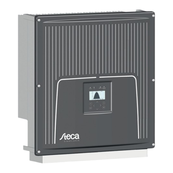
3 Gerätebeschreibung StecaGrid 20000 3ph und StecaGrid 23000 3ph Der StecaGrid 20000 3ph und StecaGrid 23000 3ph ist ein trafoloser, dreiphasiger Solarwechsel- richter, der in jedem Betriebspunkt mit besonders hohem Wirkungsgrad arbeitet und ist für den Anschluss eines PV-Generators mit einer Leistung von 21,6 kW und 25,8 kW geeignet. Die Wär- meabfuhr erfolgt durch Konvektion, eine interne Temperaturüberwachung schützt das Gerät bei Überschreitung der zulässigen Umgebungstemperatur.
Lieferumfang Zum Lieferumfang gehören die Wandhalterung und der Beipack 0030532 mit folgendem Inhalt: 1 x Kontakteinsatz IP67 5polig VC-TFS5-PEA 1 x Tüllengehäuse IP67 VC-K-T3-R-M25-PLOMB 3 x U-Scheibe Form B M8 DIN125-8 => Bei Bedarf als Unterlegscheibe verwenden für die Schrauben zur Befestigung der Wandhalterung 1 x Kabelverschraubung Schlemmer-Tec M25x1,5/21532 2 x Flachkopfschraube mit Kreuzschlitz M5x20 =>...
3.5.1 Anschlüsse Abbildung 4: Anschlüsse StecaGrid 20000 3ph und StecaGrid 23000 3ph Abhängig von der Anzahl der Anschlussleitungen sind die Eingänge wie folgt zu belegen: 3 PV-Anschlussleitungen: Eingang 1, 2, 4 oder Eingang 1, 4, 5 4 PV-Anschlussleitungen: Eingang 1, 2, 4 , 5 oder Eingang 2, 3, 5, 6 Bei mehr als 4 PV-Anschlussleitungen kann nach Belieben angeschlossen werden.
Bedienfeld Mit dem frontseitig integrierten Grafikdisplay mit 128x64 Bildpunkten lässt sich der Verlauf von Daten, wie z.B. der Einspeiseleistung oder Ertragsdaten darstellen. Die Eingabe erfolgt mit dem 8- Tasten-Bedienfeld. Das Bedienfeld wird mit dem ersten Tastendruck beleuchtet und schaltet sich automatisch wieder ab.
4 Installation Anforderungen an Montageort Lebensgefahr durch Feuer oder Explosion. Wechselrichter nicht in explosionsgefährdeten Bereichen montieren. Wechselrichter nicht auf brennbaren Baustoffen montieren. Brand- schutzklasse F30 einhalten. Wechselrichter nicht in Bereichen montieren, in denen sich leicht ent- GEFAHR flammbare Stoffe befinden.
Lagertemperatur von 40 °C maximal 1 Jahre spannungslos gelagert wer- den. Sollte die Lagerzeit von 1 Jahr überschritten sein, wenden Sie sich bitte vor dem Anlagenanschluss des Wechselrichters an den Service der Steca Elekt- ronik GmbH! 748.508 | Z01 | 2013-06-10...
Gerät auspacken Hinweis: Durch die nach dem Auspacken offenen Ein-/Ausgänge können Feuchtigkeit und Schmutz eindringen. Daher das Gerät erst auspacken, wenn es ange- schlossen werden soll. Bei Nichtbeachtung dieser Vorgabe verfällt die Ge- währleistung! Der Schwerpunkt der Geräte liegt oben. Sie werden daher mit der Unterseite nach oben verpackt. Beim Öffnen der Verpackung sieht man die Geräteunterseite (Geräteanschlüsse).
Montage Vor der Montage Lieferumfang überprüfen (siehe Kapitel 3.2, Seite 11). Verletzungsgefahr oder Sachbeschädigung Auf keinen Fall das Gerät am Deckel festhalten. Zum Bewegen des Gerätes ausschließlich die vier Haltegriffe benutzen. Bei der Auslegung der Befestigung der Wandplatte ist das Gewicht des Wechselrichters von bis zu 41,5 kg zu berücksichtigen.
5. Um Kleberückstände auf dem Wechselrichter zu vermeiden, den Displayschutz unmittelbar nach der Montage entfernen. Übersicht Geräteanschlüsse Die folgende Darstellung zeigt die Anschlüsse des Wechselrichters an der Geräteunterseite. Abbildung 9: Geräteanschluss Von links nach rechts gesehen befinden sich folgende Anschlüsse: ...
FI – Schutz Seit Februar 2009 sind für Steckdosenstromkreise bis 20 A (Innenräume), im Außenbereich bis 32 A, welche nicht von Fachpersonal genutzt werden, RCD (FI-Schalter) vorgeschrieben. Hinweis: Die transformatorlosen Photovoltaik-Netzeinspeisewechselrichter erfüllen die Anforderungen hinsichtlich des Fehlerschutzes gemäß DIN VDE 0100-712, IEC 60364-7-712:2002 und CEI 64-8/7 und können mit einem Fehlerstrom- Schutzschalter (FI, RCD) des Typs A ohne Funktionsbeeinträchtigung des Schutzes sowie des Wechselrichters betrieben werden.
4.10 DC – Anschlussleitung Folgende Informationen (Steckertyp, Anschlussquerschnitt) bezüglich der DC-Anschlussleitung beachten: Art.-Nr. Multi- Durchmesser Lei- Leiterquerschnitt Bezeichnung Type Contact tungsisolation in mm in mm² Kupplungsstecker PV-KST4/6I-UR 32.0015P0001 3 − 6 4 − 6 Kupplungsstecker PV-KST4/6II-UR 32.0017P0001 5,5 − 9 4 −...
Seite 86
Information hierzu siehe Technische Daten, Seite 54. Minderungsfaktoren bei Aneinanderreihung von Leistungsschutzschaltern sind zu berücksichtigen. Dabei sind folgende Normen zu beachten: DIN VDE 0298-4 Verlegearten und Strombelastbarkeit DIN VDE 0100; Teil 430 Schutzmaßnahmen: Schutz von Kabeln und Leitungen bei Überstrom DIN VDE 0100;...
4.12 Netzzuleitung Wählen Sie den Querschnitt der Netzanschlussleitung so, dass die Leitungsverluste so gering wie möglich sind. Folgende Punkte sind jedoch zu beachten: Als Zuleitung wird für alle Querschnitte zur leichteren Verarbeitung eine Leitung mit fei- nen Drähten empfohlen. ...
4.13 Netzleitungsinduktivität Zur Erhöhung des Wirkungsgrades werden als Netzzuleitung vermehrt hohe Leitungsquerschnitte in Einzeldraht verlegt, besonders wenn die örtlichen Gegebenheiten lange Zuleitungen erforderlich machen. Die großen Leitungslängen zwischen Wechselrichter und Transformatorstation ergeben hohe Ka- belinduktivitäten und damit eine Erhöhung der Netzimpedanz. Dies stellt hohe Widerstände für Oberwellen (harmonische) der Grundwelle (50 Hz) der Netzspannung dar und führt zu Spannungs- verzerrungen an den Wechselrichtern und zu Fehlermeldungen wie: ...
Seite 89
Schnittstelle RS485 unterstützt das USS - Protokoll (Universelles – Serielles – Schnittstellenproto- koll), welches zur Datenübermittlung z. B. an einen Datenlogger einer Fernüberwachung genutzt werden kann. Abbildung 12: Standardschnittstelle Beim Betrieb dieser Schnittstelle ist zu beachten, dass jeder Busteilnehmer eine eindeutige Adres- se benötigt.
4.15 Schnittstellenanschluss Ethernet Zum Anschluss der Ethernetschnittstelle ist ein Ethernetkabel mit dem Aufbau S/FTP (shielded Foiled Twisted Pair) und der Stecker von Phoenix Contact Typ Quickon VS-08-RJ45-5-Q/IP67 zu verwenden. Hinweis: Um die Schutzart IP65 zu gewährleisten ist oben genannter Steckertyp zwingend zu verwenden! Nichtbeachtung kann zur Beschädigung des Wechselrichters und zum Verfallen der Gewährleistung führen!
5 Inbetriebnahme Vor Inbetriebnahme des Wechselrichters müssen folgende Tätigkeiten abgeschlossen sein: Korrekt ausgeführter Netzanschluss Korrekt ausgeführter Anschluss der PV-Strings Anschlüsse gegen ungewolltes Abziehen gesichert Lebensgefahr durch Stromschlag. vor dem Einschalten den festen Sitz (Arretierung) der Anschlussstecker überprüfen.
Länderkennung und Menüsprache einstellen Die Länderkennung bestimmt die landesspezifischen Netzüberwachungsparameter. Bei der Aus- wahl der Länderkennung stellt sich automatisch die Menüsprache ein. Anschließend ist die Menü- sprache unabhängig von der Länderkennung im Menü jederzeit frei wählbar. Im Auslieferungszu- stand ist keine Länderkennung eingestellt. Gewählte Länderkennung nur vom Service änderbar.
Hinweis: Die Einstellung „Italien Option“ kann mit spezieller Genehmigung der ENEL gewählt werden, falls an einem Standort in Italien schwierige Netz- bedingungen vorherrschen. Länderkennung übernehmen Zur Sicherheit erfolgt eine Abfrage, ob die Länderkennung übernommen werden soll. Nach dem Übernehmen der Länderkennung kann sie nur noch innerhalb von 40 Stunden geändert werden.
6. Mit den Tasten ▼ und ▲ die gewünschte Menüsprache wählen. 7. Mit der Taste bestätigen. Das Menü schaltet auf die gewählte Sprache um. Das Display ist zunächst leer. 8. Taste „ESC“ betätigen, um zurück ins Menü zu gelangen. Gerätestart ...
Uac Netzspannung in Volt (V) Udc Solarzellenspannung in Volt (V) E-Tag Tagesertrag in (kWh) Zustand Betrieb Navigation über das Bedienfeld Display-Navigtion: Abbildung 14: Display Navigation Menüanzeige Funktion im Menü: Navigation innerhalb der Menü-Ebene (vorheriges Menü, nächstes Menü) <...
Passworteingabe Für die Konfiguration und Parametrierung ist häufig das Kundenpasswort 72555 erforderlich! Passworteingabe wie folgt: Konfiguration Passwort Eingabe Sprachen Kommunikation Datum / Uhr Portalüberwachung Erweitert Passwort F1-Menue F1-Menue Eingabereihenfolge (5.) (4.) (3.) (2.) (1.) Display Basisbild: Abbildung 15: Display Betrieb Pac = momentane Einspeiseleistung in Watt (w) Uac = Netzspannung in Volt (v) Udc = Solarzellenspannung in Volt (V)
Grafikanzeige: 1x die Pfeiltaste betätigen ◄, der Verlauf der Tageseinspeiseleistung wird angezeigt. Abbildung 16: Display Einspeiseleistung „Heute“ Pfeiltaste ▼ betätigen, der Verlauf der Einspeiseleistung der Vortage wird angezeigt. Abbildung 17: Display Einspeiseleistung „Gestern“ ESC-Taste betätigen, das Basisbild wird wieder angezeigt. Anzeige Ertragsdaten: 1x die Pfeiltaste ►...
Anzeige normierte Ertragsdaten: Betätigen der Pfeiltaste ►, dann die Pfeiltaste ▼, der Verlauf der normierten Ertragsdaten wird angezeigt. Abbildung 19: Display Ertragsdaten normiert Durch Betätigen der ESC-Taste, wird das Basisbild wieder angezeigt. Eingabe Normierung: Um die normierten Ertragsdaten zu erhalten Taste F2 betätigen und die dort angeschlossene PV- Generatorleistung bei Parameter P1155 wie folgt eintragen: Tasten ◄►: Betätigung der Taste ◄...
Seite 100
Menü Ebene 1 Menüs Ebene 2 Menüs Ebene 3 Menüs Ebene 4 Anzeige oder Eingabe (Siehe:*1) IP-Adresse Eingabe IP-Adresse Subnetmaske Eingabe Subnetmaske Standardgateway Eingabe Standardgateway Protokoll-Port Protokoll-Port RS485 USS-Adresse Eingabe USS-Adresse (Siehe:*1) Protokoll Eingabe Protokoll Baudrate Eingabe Baudrate Datum / Uhrzeit Eingabe von Datum / Uhrzeit Portalüber-...
Seite 101
Detail – Erklärungen *1. Kommunikation über Ethernet Protokoll: Eingabe 0 oder 1 0 = RTP – Protokoll 1 = USS – und RTP – Protokoll Protokoll – Port: Eingabe 1024….65535; Standardeinstellung 21062 Portnummer wird zur Kommunikation über Ethernet benötigt *2. Kommunikation über RS485 USS –...
6 Konfiguration Reduzierung der Ausgangsleistung Zur Begrenzung der Ausgangsleistung des Wechselrichters wie folgt vorgehen: 1. Kundenpasswort „72555“ eingeben. 2. Mit Taste F1 Menüpunkt Konfiguration wählen und mit Taste bestätigen. 3. Untermenü „Reduzierung PAC“ auswählen und mit Taste bestätigen. 4. Gewünschte Wechselrichter-Ausgangsleistung eingeben und mit Taste bestätigen.
Adresse ist notwendig um über RS485 mit dem Wechselrichter zu kommunizieren. Hinweis: Wird dieser Wert (Adresse) geändert und soll gespeichert werden, ist der Wechselrichter neu zu starten! Die neue Adresse ist danach aktiv. Protokollabfrage über Ethernet: Eingabe 1, 2 und 3 1: USS - und RTP –...
7 Fehlerbehebung Selbsttest – Fehlermeldungen Nach der Initialisierungsroutine führt das System einen Selbsttest durch. Es werden dabei die ein- zelnen Teile des Systems, wie z.B. Firmware und Datensatz, überprüft und Daten von der Leis- tungssteuerungsplatine eingelesen. Sollte weiterhin ein Fehler festgestellt werden, ergeben sich mögliche Abhilfemaßnahmen aus der Art des Fehlers.
Seite 107
Fehler- Fehlertext Beschreibung Maßnahme nummer 0X30002 Parameterfehler 1 Bei der Initialisierung der Son- derfunktionen wurde eine de- 0X30005 Parameterfehler 2 fekte Parameterdatei gefunden Bitte ein Update durch den Die Anzahl der Parameter Service veranlassen. stimmt nicht mit der Anzahl der 0X30006 Parameterfehler 3 Parameter im Dateisystem...
Seite 108
Asymmetrie low: Differenz der 0A0003 Reglerspannung 3 beiden Solarspannungen ist zu groß. Asymmetrie high: Differenz der beiden hochgesetzten Zwi- 0A0004 Reglerspannung 4 schenkreisspannungen ist zu groß. Absinken des positiv hochge- 0A0005 Reglerspannung 5 setzten Zwischenkreises unter Netzscheitelwert. Absinken des negativ hochge- Bei einmaligem Auftreten: War- 0A0006 Reglerspannung 6...
Seite 109
Solange der Wechselrichter eine Netzüberspannung des Außenlei- ters feststellt: Außenleiterspan- Erkennung von Netzüberspan- nungen überprüfen (Mit einem 0A000F Netzüberspg.Außenl. nung auf dem Außenleiter True RMS Messgerät). Sollten die Außenleiterspannungen Ihres Erachtens nach in Ordnung sein kontaktieren Sie den Service. Solange der Wechselrichter eine Netzunterspannung des Außen- leiters feststellt: Außeneiterspan- Erkennung von Netzunter-...
Seite 110
Solange der Wechselrichter den Spannungsfehler Min feststellt: Die Netznennspannung lag zu Leiterspannungen überwachen lange unter dem Grenzwert 0A0019 Spannungsfehler min (Netzanalyse). Sollten die Leiter- der Spannungs-Mittelwert- spannungen Ihres Erachtens Überwachung nach in Ordnung sein kontaktie- ren Sie den Service Es sind weitere Fehler mit dem 0A0100 Störmeldung LT Störmeldung vom Leistungsteil...
Seite 111
Beobachten: Wann tritt der Fehler Hardwareabschaltung des 0A010E Gerätestörung LT auf (genau: Wochentag, kW- Leistungsteils Leistung, Uhrzeit Überspannungsabschaltung 0A0110 Solarspannung LT 1 des Leistungsteils im positiven Nichts unternehmen, Fehler wird Zwischenkreis vom Wechselrichter selbst quit- tiert. Bei mehrmaligem Auftreten Überspannungsabschaltung Service kontaktieren.
Seite 112
0x0B0001 System 1 Fehler in der Fehlerverwaltung 0x0B0002 System 2 Fehlerspeicher ist voll Kontaktieren Sie den Service Fehlerquittierung fehlgeschla- 0x0B0003 System 3 1.) Gerät mit DC- Trennschalter ausschalten. 2.) Warten bis das Display kom- Es konnte beim Firmwareup- plett aus ist. date keine Verbindung zum 0X0D0001 Systemfehler...
Temperatursensor angeschlossen werden. Empfohlen wird der Typ Si-13TC-T-K, Steca Arti- kelnummer 748297. Zum Lieferumfang des Einstrahlungs- und Temperatursensors gehört der Sensorstecker. Der Sensorstecker ist auch separat unter der Artikelnummer 748298 bei Steca Elektronik GmbH bestellbar. Der Sensor wird mit einer drei Meter langen UV-stabilen Anschlussleitung (5 x 0,14 mm²) geliefert.
Abbildung 22: Sensoranschluss Die Daten des Si-13TC-T-K können über folgende Parameter abgerufen werden: D 1191.00 => Einstrahlung 0-10 V => 0-1300 W/m² D 1193.00 => Temperatur 0-10 V => -26,1° C – 90° C Diese Daten können ebenfalls im Datenlogger aufgezeichnet werden. Hinweis: Wird der Temperatureingang nicht benützt, muss eine Brücke zwischen PIN4 und PIN5 verdrahtet werden! Alternativ kann die Brücke auch an der...
® Geräteeinstellungen für die Überwachung mit SolarLog ® oder MeteoControl Alle Wechselrichter müssen mit Firmware-Version RTF-80xR0xx-25-x-S oder höher ausgerüstet sein (einsehbar in: Menü F1\Geräteinformation\Versionskennung\RFP...). Die RS485-Schnittstelle (RS485 IN/OUT) ist bei allen Wechselrichtern Standard. ® ® muss jedem StecaGrid 20000 3ph oder Für die Kommunikation über SolarLog oder MeteoControl StecaGrid 230003 ph eine Kommunikations-Adresse vergeben werden.
Datenloggerparameter Diese Parameter dienen zur Einstellung des internen Datenloggers Parameterbezeichnung Beschreibung Parameter- nummer Schaltet den Datenlogger ein oder aus. P450.00 Datenlogger eingeschaltet 0 = Ausgeschaltet. 1 = Eingeschaltet. Daten werden nun regelmäßig aufgezeichnet Enthält das Zeitintervall (60 / 300 / 600 Sek.) in dem der Daten- P451.00 Datenlogger Zeitintervall logger Werte speichert.
9 Wartung Da die Kühlung der Wechselrichter ausschließlich durch natürliche Konvektion erfolgt, sind für ei- nen sicheren Betrieb entsprechend den Umgebungsbedingungen die Kühlrippen des Kühlkörpers auf Verschmutzung zu überprüfen und ggf. von abgelagertem Staub / Schmutz zu reinigen. Der DC-Trennschalter ist für lange Lebensdauer konzipiert. Für die Wartung reicht es aus, den DC- Trennschalter, einmal im Jahr 5-mal hintereinander, ohne Last zu betätigen.
Kommunikationsschnittstelle RS485; Ethernet Einspeisemanagement nach EEG 2012 EinsMan-ready, über RS485-Schnittstelle Integrierter DC-Lasttrennschalter ja, konform zu DIN VDE 0100-712 Kühlprinzip natürliche Konvektion Prüfbescheinigung CE-Zeichen, Unbedenklichkeitsbescheinigung nach DIN VDE 0126-1-1, VDE AR N 4105, G59, AS4777, UTE C 15-712-1, CEI 0-21, C10/C11 10.2 Sensor Si-13TC-T-K Allgemein...
11 Haftungsausschluss Sowohl das Einhalten dieser Anleitung als auch die Bedingungen und Methoden bei Installation, Betrieb, Verwendung und Wartung des Wechselrichters können vom Hersteller nicht überwacht werden. Eine unsachgemäße Ausführung der Installation kann zu Sachschäden führen und in Fol- ge Personen gefährden. Daher übernehmen wir keinerlei Verantwortung und Haftung für Verluste, Schäden oder Kosten, die sich aus fehlerhafter Installation, unsachgemäßem Betrieb sowie falscher Verwendung und Wartung ergeben oder in irgendeiner Weise damit zusammenhängen.
Um die Garantie in Anspruch nehmen zu können, muss der Kunde den Zahlungsnachweis (Kauf- beleg) vorlegen. Sollte der Kunde ein Problem feststellen, hat er sich mit seinem Installateur oder der Steca Elekt- ronik GmbH in Verbindung zu setzen. 3. Garantieausschluss Die oben unter Punkt 1 beschriebenen Garantien auf Produkte von der Steca Elektronik GmbH gelten nicht für den Fall, dass der Fehler zurückzuführen ist auf: (1) Spezifikationen, Entwurf, Zu-...
13 Kontakt Bei Reklamationen und Störungen bitten wir Sie, sich mit Ihrem lokalen Händler in Verbindung zu setzen, bei dem Sie das Produkt gekauft haben. Dieser wird Ihnen in allen Belangen weiterhelfen. Europa Steca Elektronik GmbH Mammostraße 1 87700 Memmingen Deutschland...
Seite 125
Indice Avvertenze di sicurezza......................3 Introduzione........................3 Spiegazioni ........................3 Pericoli a seguito di utilizzo errato...................4 Informazioni generali .......................4 Protezione contro il contatto di parti elettriche ..............5 Protezione contro campi magn. ed elettromagn. durante funzionamento/montaggio ..6 Protezione contro il contatto di parti calde ..............7 Impostazione del codice paese ..................7 Protezione durante l’utilizzo e il montaggio..............8 1.10...
Seite 126
Impostazione del codice paese e della lingua menu.............26 Attivazione dell’apparecchio..................28 Navigazione attraverso il pannello di comando.............30 Inserimento password ....................31 Struttura del menu......................34 Test ENS ........................42 Eliminazione guasti........................44 Autotest – messaggi di errore ..................44 Guasto di breve durata....................44 Guasti ..........................44 Conferma di un guasto ....................44 Elenco dei messaggi di guasto..................45 Opzioni ............................48 Connettori per il collegamento alla rete.................48...
Ciò vale anche per le istruzioni di sicurezza e per tutte le altre avver- tenze per l’utilizzatore prima di iniziare qualsiasi lavoro con questo apparecchio. Se non dovessero essere disponibili le avvertenze per l’utilizzatore relative al presente apparecchio, rivolgersi a Steca GmbH. Richiedere l’immediato invio di questa documentazione al responsabile del funzionamento sicuro dell’apparecchio.
1.3 Pericoli a seguito di utilizzo errato Elevata tensione elettrica ed elevata corrente di lavoro! Pericolo di morte o di gravi lesioni fisiche a seguito di scossa elettrica! PERICOLO Elevata tensione elettrica a causa di collegamento errato! Pericolo di morte o di lesioni fisiche a seguito di scossa elettrica! AVVERTIMENTO Elevata corrente di dispersione!
Su questo apparecchio deve lavorare solo personale formato e qualificato. Il personale s’intende qualificato quando ha sufficiente familiarità con il montaggio, l’installazione e l’utilizzo del prodot- to, nonché con tutti gli avvertimenti e le misure di sicurezza contenuti in questo manuale d’uso. Inoltre, il personale deve essere formato, addestrato o autorizzato a attivare e disattivare circuiti di corrente e apparecchi secondo le disposizioni della tecnica di sicurezza, di metterli a terra e di identificarli correttamente secondo i requisiti lavorativi.
Tensione elettrica elevata! Pericolo di morte, di lesioni a seguito di scossa elettrica o gravi lesioni fisiche! L’installazione di StecaGrid deve essere eseguita solo da personale tecnico formato. Inoltre, l’installatore deve essere autorizzato da azien- de erogatrici di elettricità competenti. ...
ATTENZIONE lamento, il codice paese può essere modificato solo dal personale del servizio di assistenza. Revoca dell’omologazione! L’utilizzo di Steca con un codice paese errato può comportare la revoca dell’omologazione da parte dell’ente di distribuzione dell’energia. ATTENZIONE Nota Si declina ogni responsabilità per eventuali conseguenze derivanti da un’errata impostazione del codice paese!
Rispettare le norme generali di installazione e di sicurezza in merito all’utilizzo e al montaggio. Il peso del Steca è di 40 kg ! Utilizzare dispositivi di montaggio e di trasporto idonei. Evitare impigliamenti e schiacciamenti mediante misure preventive adatte.
2 Descrizione StecaGrid 20000 3ph e 23000 3ph 2.1 Descrizione dell’apparecchio Il StecaGrid è un inverter solare trifase senza trasformatore che funziona in ogni punto di esercizio con un rendimento particolarmente elevato e che è indicato per il collegamento di un generatore FV con una potenza di 21,6 kW e 25,8 kW.
Con la custodia mobile IP67 VC-K-T3-R-M25-PLOMB è possibile una una piombatura in conf. con DK5940. La piombatura viene fissata attraverso un foro nella vite (al di sotto della testa della vite della custo- dia mobile) e nell'apposita apertura della custodia mobile. 2.3 Dimensioni esterne StecaGrid 20000 3ph e 23000 3ph Figura No.
MC4. In caso di mancata osservanza di questa prescrizione, la classe di protezione IP65 non è più garantita! Entrambi i tappi di chiusura (+/-) possono essere richiesti a Steca GmbH in qualsiasi momento con i codici ordine 0028991 e 0028992!
Figura No. 4 Collegamento generatore FV StecaGrid 20000 3ph e 23000 3ph StecaGrid 20000 3ph e 23000 3ph: 3 cavi di collegamento FV ingresso 1, 3 e 5 o ingresso 2, 4 e 6 4 cavi di collegamento FV ingresso 1, 2, 4, 5 o ingresso 2, 3, 5, 6 Con diversi cavi di collegamento FV è...
2.7 Pannello di controllo Il display grafico integrato nel pannello anteriore con 128 x 64 pixel consente di visualizzare l’andamento di dati interessanti quali, ad esempio, la potenza di alimentazione. La scelta e l’inserimento dei parametri necessari avviene mediante il pannello di controllo a 8 tasti. Il pannello di controllo si illumina alla prima pressione di un tasto e si rispegne automaticamente.
3 Installazione 3.1 Disimballaggio dell'apparecchio Il baricentro degli apparati si trova nella parte superiore, pertanto vengono imballati capovolti al fine di facilitare il transporto. All'apertura dell'imballaggio si vede la parte inferiore dell'apparecchio (colle- gamenti). L'apparecchio può essere estratto dall'imballaggio tramite le due maniglie laterali. Durante il disimballaggio dell'apparecchio la griglia dell'imballaggio rimane fissata alla custodia mobile e può...
Seite 139
Il miglior comfort di impiego si ottiene scegliendo una posizione di installazione ad altezza occhi. Il grado di protezione IP65 consente anche un montaggio all’esterno. Nota: Al fine di garantire il grado di protezione IP65, utilizzare per il collegamento del StecaGrid i connettori maschi/femmina in dotazione e collegarli seguendo le istruzioni di montaggio del produttore dei connettori.
StecaGrid contiene condensatori a elettroliti. Possono essere stoccati senza tensione ad una temperatura 40°C al massimo per 2 anni. Se si supera il tempo di stoccaggio di 1 anno, rivolgersi al servizio di assistenza di Steca E- lektronik GmbH prima di collegare il StecaGrid! 3.5 Montaggio StecaGrid 20000 3ph e 23000 3ph...
Seite 141
Non è permesso aprire l’apparecchio! In caso d’inosservanza possono penetrare polvere, residui e umidità, o le componenti possono venire danneggiate a causa della scarica elet- ATTENZIONE trostatica. Anche il grado di protezione IP 65 non può più essere così garantito. Nessuna garanzia per eventuali danni così...
è esclusivamente necessario che il PE sia messo a terra tramite il bullone di messa a terra. Con l’utilizzo della rete TT, Steca Elektronik GmbH consiglia un interruttore di circuito FI. Il cavo di collegamento deve essere dotato di un'adeguata protezione. Per ulteriori informazioni si veda Dati tecnici 8.1, p.
Seite 143
DIN VDE 0298-4 Tipi di posa e capacità di trasporto di corrente DIN VDE 0100; Parte 430 Misure di protezione: Protezione di cavi e conduttori in caso di sovracorrente DIN VDE 0100; Parte 410 Misure di protezione: protezione contro scossa elettrica Rispettare inoltre i seguenti parametri del gestore di rete locale: ...
3.8 Alimentazione di rete Scegliere la sezione del cavo di collegamento di rete in modo che le perdite di linea siano minime. Rispettare tuttavia i seguenti punti: Come linea di alimentazione si raccomanda per tutte le sezioni un cavo a fili sottili, per via della lavorazione.
Distanza minima tra i singoli fili! Se possibile, evitare la posa lungo materiali a conduzione magnetica. Nota: La somma della caduta di tensione ohmica e induttiva sul cavo di rete in caso di carico nominale non dovrebbe superare l'1% della tensione nominale. Assi- curarsi che l'induttanza di rete si mantenga <...
3.11 Protezione FI A partire da febbraio 2009 per i circuiti con prese fino a 20 A (interni), all'esterno fino a 32 A, utilizzati da persone non esperte in campo elettrotecnico, è previsto l'impiego di un RCD (interruttore FI). Nota: Gli inverter fotovoltaici senza trasformatore soddisfano i requisiti in materia di protezione contro i guasti DIN VDE 0100-712, IEC 60364-7-712:2002 e CEI 64-8/7 e possono essere azionati con un interruttore di protezione dalle cor-...
3.13 Cavo di collegamento DC Si prega di notare le seguenti informazioni (tipo di spina, sezione cavo) per quanto riguarda il cavo CC . Denominazione Tipi Art. N. Diametro dei conduttore Sezione del cavo en isolamento en mm mm² MultiContact Connettore di accoppiamento PV-KST4/6I-UR 32.0015P0001 3 -6...
Per l’utilizzo di questa interfaccia accertarsi che ogni utenza bus necessiti di un indirizzo chiaro. La terminazione bus avviene mediante ponticelli su X14 dell’ultima utenza bus (inverter “n“). Figura No. 13 Connettore M12 x 1 dritto, schermato ; schema connettore maschio M12, 4 poli, codificato A Vista lato spina Nota: I cavi di collegamento per RS485 interfaccia devono essere schermati!
4 Messa in funzione Prima di mettere in funzione il StecaGrid è necessario aver completato le seguenti operazioni: Collegamento alla rete correttamente eseguito Collegamento delle stringhe FV correttamente eseguito Collegamenti protetti contro l’estrazione accidentale Pericolo di scossa elettrica! ●...
4.2 Impostazione del codice paese e della lingua menu Il codice paese determina i parametri di controllo di rete specifici per paese. Con la selezione del codice paese, la lingua menu viene impostata automaticamente. In seguito, è tuttavia pos- sibile selezionare liberamente nel menu qualsiasi lingua, a prescindere dal codice paese im- postato.
Seite 151
1. Selezionare il codice paese pertinente al luogo specifico di impiego con i tasti freccia ▲ e ▼. - Con il codice paese viene contemporaneamente selezionata anche la lingua menu. - La lingua menu può essere modificata in qualsiasi momento dal menu. 2.
5. Confermare con il tasto “ ”. 6. Selezionare con i tasti freccia ▼ e ▲ la lingua menu desiderata. 7. Confermare con il tasto “ ”. Il menu passa alla lingua selezionata. In un primo momento il display è vuoto. 8.
Seite 153
Visualizzazione sul display: Pac Potenza di alimentazione in Watt (W) Uac Tensione di rete in Volt (V) Udc Tensione delle celle solari in Volt (V) Disattivato Figura No. 15 Attivazione display apparecchio Con tensione delle celle solari > 350V si attiva il processo di accensione: ...
Aprire il menu con il tasto F1. Selezionare con la freccia ▼ la voce di menu “Configurazione“ e scegliere tramite / ►. Selezionare con la freccia ▼ la voce di menu “Data / ora“ e scegliere tramite / ►. Impostare con i tasti freccia ►◄ giorno, mese, anno, ora, minuti e secondi in successione. Confermare l'inserimento con il tasto 4.4 Navigazione attraverso il pannello di comando Display di navigazione:...
4.5 Inserimento password Per la configurazione e la parametrizzazione viene spesso richiesta la password cliente! Inserire la password seguente: Configurazione Input Password Lingue Comunicazione Data / Orario Controllo portale Esteso Password F1-Menue F1-Menue Input in ordine numerico (5.) (4.) (3.) (2.) (1.) La password cliente è: 72555...
Seite 156
Visualizzazione grafica: Se si preme una volta il tasto freccia ◄, viene visualizzato l’andamento della potenza di alimentazio- ne giornaliera. Figura No. 18 Display potenza di alimentazione „Oggi“ Se si preme il tasto freccia ▼, viene visualizzato l’andamento della potenza di alimentazione dei giorni precedenti.
Seite 157
Visualizzazione dati rendimento normalizzati: Se si preme due volte il tasto freccia ►, e poi il tasto freccia ▼, viene visualizzato l’andamento dei dati di rendimento normalizzati. La potenza del generatore effettivamente collegata (“Norm P“) può essere inserita dalla voce di me- nu “Elenco numerico“...
4.6 Struttura del menu La struttura del menu serve come supporto per la commutazione sulle singole visualizzazioni infor- mative e sul display di impostazione. Legenda: Leggenda – tastiera del pannello di controllo Indietro e indietro al menu principale Indieto Conferma Freccia destra / sinistra Freccia sopra / sotto 748.508 | Z01 | 2013-06-10...
Seite 160
Memoria guasti Memoria guasti F02 Sottotensione di rete F02 Sottotensione di rete F03 Riavvio sistema F03 Riavvio sistema F04 Riavvio sistema F04 Riavvio sistema 21.10.2009 13:56:24 0X00D0003 F05 Riavvio sistema F05 Riavvio sistema F06 Riavvio sistema F06 Riavvio sistema F1-Menue F1-Menue Analisi Configurazione...
Seite 161
Vedere:*1 Configurazione Indirizzo IP Comunicazione Ethernet Indirizzo USS 192.168 0.123 Protocollo Indirizzo IP Maschera Subnet F1-Menue F1-Menue Configurazione Maschera Subnet Comunicazione Ethernet Indirizzo USS 255.255.254. 0 Protocollo Indirizzo IP Maschera Subnet F1-Menue F1-Menue Configurazione Standardgateway Comunicazione Ethernet Protocollo 10.104.120. 1 Indirizzo IP Maschera Subnet Standardgateway...
Seite 162
Configurazione Data / Orario Lingue Comunicazione Data / Orario 330.10.2009 14:02:32 Controllo portale Esteso Password F1-Menue F1-Menue Configurazione Configurazione Attivazione Lingue Controllo portale Comunicazione Attivazione Data / Orario Configurazione Controllo portale IP portale web Esteso Porta portale web Password Test di portale F1-Menue F1-Menue F1-Menue...
Seite 163
Configurazione Configurazione Configurazione Lingue Esteso Esteso Comunicazione Update XMODEM Update XMODEM Data / Orario Cancella data logger Sì - Update XMODEM Controllo portale Numero elenco Esteso ENS-Test Password F1-Menue F1-Menue F1-Menue Vedere:Fehler! Verweisquelle konnte nicht gefunden werden. Configurazione Configurazione Esteso Esteso Update XMODEM Cancella data logger...
Seite 164
Configurazione Input password Lingue Comunicazione Data / Orario Controllo portale Esteso Password F1-Menue F1-Menue Analisi Info apparato Versione Valori reali Versione Memoria guasti Paese d'impiego Configurazione Lingua attuale Info apparato Tipo di apparato RFP-800R015-25-6-S Numero seriale F1-Menue F1-Menue F1-Menue Info apparato Einsatzland Versione Paese d'impiego...
Seite 165
Dettaglio – Spiegazioni *1. Comunicazione tramite Ethernet Indirizzo USS: Impostato di fabbrica e non modificabile. Protocollo: Inserimento 0 o 1 0 = protocollo RTP 1 = protocollo USS e RTP Porta protocollo: Inserimento 1024….65535; impostazione standard 21062. Il numero di porta è necessario per la comunicazione tramite Ethernet. *2.
4.7 Test ENS Configurazione ENS-Test P0900. Esteso P0900 Start test ENS Update XMODEM D0901 Cancella data logger P0908 Numero elenco D0902 ENS-Test D0910. ─ F1-Menue F1-Menue F1-Menue ENS-Test D0904. D0910. Risultato del test d i tensione D0903. D0903. P0909 11500 Volt D0904 F1-Menue...
Seite 167
Elenco stati del test ENS: Inizializzazione/pronto all'avvio 1 … 3 Test di frequenza per il limite inferiore di frequenza 4 … 6 Test di frequenza per il limite superiore di frequenza 7 … 9 Test della tensione verso il limite di tensione inferiore 10 …...
5 Eliminazione guasti 5.1 Autotest – messaggi di errore Al termine della routine di inizializzazione, il sistema esegue un autotest. Vengono controllati i singoli componenti del sistema, come ad es. il firmware e il record di dati e vengono letti i dati dalla scheda di controllo di potenza.
5.5 Elenco dei messaggi di guasto Codice Testo errore Descrizione Misura guasto Regolazione convertitore boost-up Attendere che si stabilizzi rego- 0A0001 Tens.regolatore 1 dello stadio intermedio positivo latore impossibile Regolazione convertitore boost-up Attendere che si stabilizzi rego- 0A0002 Tens. regolatore 2 dello stadio intermedio negativo latore impossibile...
Seite 170
Codice Testo errore Descrizione Misura guasto Controllare frequenza e tensio- 0A0011 Frequenza rete FLL Rilievo errore di rete (FLL) ne di rete. Service se frequen- za di rete nel range consentito Controllare frequenza e tensio- Rilievo errore di frequenza 0A0012 Frequenza di rete ne di rete.
Seite 171
Codice Testo errore Descrizione Misura guasto Cod. paese in- Codice paese non compatibile con 0A0113 Service cons.LT subcodice Rilievo di corrente differenziale Sensore AFI non funzionante, 0A0114 Isolam. gen. AFILT nell'unità di potenza riavvio, controllare contatti Rilievo di corrente differenziale Sensore AFI non funzionante, 0A0115 Allarme AFI...
In via opzionale è possibile collegare un sensore di irradiazione per il rilevamento dell‘irradiazione solare e della temperatura del modulo. Si consiglia il tipo Si-13TC-T-K. n. art. Steca 748297. Nella dotazione del sensore di irradiazione è compreso il connettore del sensore. Il connettore del sensore può...
Figura No. 24 Collegamento sensore solare – di irradiazione I dati del sensore Si-13TC-T-K possono essere selezionati dai seguenti parametri: D 1191.00 => irradiazione 0-10 V => 0-1300 W/m² D 1193.00 => temperatura 0-10 V => -26,1° C – 90° C Questi dati possono essere altresì...
® 6.4 Impostazioni dell´apparecchio per il controllo con SolarLog ® o MeteoControl Tutti gli inverter devono essere equipaggiati con Firmware versione RTF-80xR0xx-25-x-S o mag- giore (visionabile in: Menu F1\Informazione apparecchio\Caratteristica versione\RFP...). L'interfaccia RS485 (RS485 IN/OUT) è standard in tutti i StecaGrid. ®...
7 Manutenzione Poiché il raffreddamento della StecaGrid 20000 3ph e 23000 3ph è dovuto esclusivamente alla con- vezione naturale sono controllati per un funzionamento sicuro secondo l'ambiente, le alette di raf- freddamento del dissipatore di calore per lo sporco e se necessario pulire di polvere / sporcizia. Il DC-switch è...
8 Dati tecnici 8.1 Inverter solare StecaGrid 20000 3ph e 23000 3ph Dati tecnici a 25 °C/77 °F Tipo StecaGrid 20000 3ph StecaGrid 230003 ph Lato ingresso CC (generatore FV) Numero degli ingressi CC Tensione di avvio massima 1.000 V Tensione di ingresso massima 1.000 V Tensione MPP per potenza nominale...
Interfaccia di comunicazione RS485; Ethernet Interruttore CC integrato sì, conforme a VDE 0100-712 Principio di refrigerazione convezione naturale Certificazione di controllo marchio CE, nullaosta secondo DIN VDE 0126-1-1, VDE AR N 4105, G59, G83, AS4777, UTE C 15-712-1, CEI 0-21, C10/C11 8.2 Sensore di irradiazione Tipo Si-13TC-T-K...
9 Esclusione di responsabilità Il produttore non è in grado di controllare l'osservanza delle disposizioni contenute nelle presenti istruzioni, né le condizioni e i metodi d'installazione, di funzionamento, di utilizzo e di manutenzione dell'inverter. L'installazione eseguita in maniera non corretta può causare dei danni e pertanto costi- tuire un pericolo per le persone.
Se il cliente constata un problema deve contattare il suo installatore o la Steca Elektronik GmbH. 10.3 Esclusione di garanzia Le garanzie descritte sopra al punto 1 su prodotti della Steca Elektronik GmbH non valgono nel caso in cui il guasto sia da ricondursi a: (1) specificazioni, progetto, accessori o componenti aggiunti dal...
11 Contatti In caso di reclami o guasti si prega di rivolgersi al rivenditore presso il quale è stato acquistato l'ap- parecchio, che fornirà un’assistenza completa. Europa Steca Elektronik GmbH Mammostrasse 1 87700 Memmingen Germania +39 (0) 02 509 901 +49 700 STECAGRID Dal lunedì...
12 Certificati Certificati aggiuntivi sono disponibili a www.stecasolar.com → FV connessione alla rete → Inverter per la connessione in rete → StecaGrid 20000 3ph/23000 3ph. 748.508 | Z01 | 2013-06-10...